EP2594767A1 - Apparatus for controlling internal combustion engine - Google Patents
Apparatus for controlling internal combustion engine Download PDFInfo
- Publication number
- EP2594767A1 EP2594767A1 EP10854701.9A EP10854701A EP2594767A1 EP 2594767 A1 EP2594767 A1 EP 2594767A1 EP 10854701 A EP10854701 A EP 10854701A EP 2594767 A1 EP2594767 A1 EP 2594767A1
- Authority
- EP
- European Patent Office
- Prior art keywords
- valve
- fuel
- exhaust
- addition
- period
- Prior art date
- Legal status (The legal status is an assumption and is not a legal conclusion. Google has not performed a legal analysis and makes no representation as to the accuracy of the status listed.)
- Granted
Links
Images





Classifications
-
- F—MECHANICAL ENGINEERING; LIGHTING; HEATING; WEAPONS; BLASTING
- F01—MACHINES OR ENGINES IN GENERAL; ENGINE PLANTS IN GENERAL; STEAM ENGINES
- F01N—GAS-FLOW SILENCERS OR EXHAUST APPARATUS FOR MACHINES OR ENGINES IN GENERAL; GAS-FLOW SILENCERS OR EXHAUST APPARATUS FOR INTERNAL-COMBUSTION ENGINES
- F01N3/00—Exhaust or silencing apparatus having means for purifying, rendering innocuous, or otherwise treating exhaust
- F01N3/08—Exhaust or silencing apparatus having means for purifying, rendering innocuous, or otherwise treating exhaust for rendering innocuous
- F01N3/0807—Exhaust or silencing apparatus having means for purifying, rendering innocuous, or otherwise treating exhaust for rendering innocuous by using absorbents or adsorbents
- F01N3/0821—Exhaust or silencing apparatus having means for purifying, rendering innocuous, or otherwise treating exhaust for rendering innocuous by using absorbents or adsorbents combined with particulate filter
-
- F—MECHANICAL ENGINEERING; LIGHTING; HEATING; WEAPONS; BLASTING
- F01—MACHINES OR ENGINES IN GENERAL; ENGINE PLANTS IN GENERAL; STEAM ENGINES
- F01N—GAS-FLOW SILENCERS OR EXHAUST APPARATUS FOR MACHINES OR ENGINES IN GENERAL; GAS-FLOW SILENCERS OR EXHAUST APPARATUS FOR INTERNAL-COMBUSTION ENGINES
- F01N3/00—Exhaust or silencing apparatus having means for purifying, rendering innocuous, or otherwise treating exhaust
- F01N3/08—Exhaust or silencing apparatus having means for purifying, rendering innocuous, or otherwise treating exhaust for rendering innocuous
- F01N3/0807—Exhaust or silencing apparatus having means for purifying, rendering innocuous, or otherwise treating exhaust for rendering innocuous by using absorbents or adsorbents
- F01N3/0828—Exhaust or silencing apparatus having means for purifying, rendering innocuous, or otherwise treating exhaust for rendering innocuous by using absorbents or adsorbents characterised by the absorbed or adsorbed substances
- F01N3/0842—Nitrogen oxides
-
- F—MECHANICAL ENGINEERING; LIGHTING; HEATING; WEAPONS; BLASTING
- F01—MACHINES OR ENGINES IN GENERAL; ENGINE PLANTS IN GENERAL; STEAM ENGINES
- F01N—GAS-FLOW SILENCERS OR EXHAUST APPARATUS FOR MACHINES OR ENGINES IN GENERAL; GAS-FLOW SILENCERS OR EXHAUST APPARATUS FOR INTERNAL-COMBUSTION ENGINES
- F01N3/00—Exhaust or silencing apparatus having means for purifying, rendering innocuous, or otherwise treating exhaust
- F01N3/08—Exhaust or silencing apparatus having means for purifying, rendering innocuous, or otherwise treating exhaust for rendering innocuous
- F01N3/0807—Exhaust or silencing apparatus having means for purifying, rendering innocuous, or otherwise treating exhaust for rendering innocuous by using absorbents or adsorbents
- F01N3/0871—Exhaust or silencing apparatus having means for purifying, rendering innocuous, or otherwise treating exhaust for rendering innocuous by using absorbents or adsorbents using means for controlling, e.g. purging, the absorbents or adsorbents
-
- F—MECHANICAL ENGINEERING; LIGHTING; HEATING; WEAPONS; BLASTING
- F01—MACHINES OR ENGINES IN GENERAL; ENGINE PLANTS IN GENERAL; STEAM ENGINES
- F01N—GAS-FLOW SILENCERS OR EXHAUST APPARATUS FOR MACHINES OR ENGINES IN GENERAL; GAS-FLOW SILENCERS OR EXHAUST APPARATUS FOR INTERNAL-COMBUSTION ENGINES
- F01N9/00—Electrical control of exhaust gas treating apparatus
-
- F—MECHANICAL ENGINEERING; LIGHTING; HEATING; WEAPONS; BLASTING
- F01—MACHINES OR ENGINES IN GENERAL; ENGINE PLANTS IN GENERAL; STEAM ENGINES
- F01N—GAS-FLOW SILENCERS OR EXHAUST APPARATUS FOR MACHINES OR ENGINES IN GENERAL; GAS-FLOW SILENCERS OR EXHAUST APPARATUS FOR INTERNAL-COMBUSTION ENGINES
- F01N9/00—Electrical control of exhaust gas treating apparatus
- F01N9/002—Electrical control of exhaust gas treating apparatus of filter regeneration
-
- F—MECHANICAL ENGINEERING; LIGHTING; HEATING; WEAPONS; BLASTING
- F02—COMBUSTION ENGINES; HOT-GAS OR COMBUSTION-PRODUCT ENGINE PLANTS
- F02D—CONTROLLING COMBUSTION ENGINES
- F02D13/00—Controlling the engine output power by varying inlet or exhaust valve operating characteristics, e.g. timing
- F02D13/02—Controlling the engine output power by varying inlet or exhaust valve operating characteristics, e.g. timing during engine operation
- F02D13/0203—Variable control of intake and exhaust valves
- F02D13/0215—Variable control of intake and exhaust valves changing the valve timing only
- F02D13/0219—Variable control of intake and exhaust valves changing the valve timing only by shifting the phase, i.e. the opening periods of the valves are constant
-
- F—MECHANICAL ENGINEERING; LIGHTING; HEATING; WEAPONS; BLASTING
- F02—COMBUSTION ENGINES; HOT-GAS OR COMBUSTION-PRODUCT ENGINE PLANTS
- F02D—CONTROLLING COMBUSTION ENGINES
- F02D13/00—Controlling the engine output power by varying inlet or exhaust valve operating characteristics, e.g. timing
- F02D13/02—Controlling the engine output power by varying inlet or exhaust valve operating characteristics, e.g. timing during engine operation
- F02D13/0242—Variable control of the exhaust valves only
- F02D13/0249—Variable control of the exhaust valves only changing the valve timing only
-
- F—MECHANICAL ENGINEERING; LIGHTING; HEATING; WEAPONS; BLASTING
- F01—MACHINES OR ENGINES IN GENERAL; ENGINE PLANTS IN GENERAL; STEAM ENGINES
- F01L—CYCLICALLY OPERATING VALVES FOR MACHINES OR ENGINES
- F01L1/00—Valve-gear or valve arrangements, e.g. lift-valve gear
- F01L1/34—Valve-gear or valve arrangements, e.g. lift-valve gear characterised by the provision of means for changing the timing of the valves without changing the duration of opening and without affecting the magnitude of the valve lift
-
- F—MECHANICAL ENGINEERING; LIGHTING; HEATING; WEAPONS; BLASTING
- F01—MACHINES OR ENGINES IN GENERAL; ENGINE PLANTS IN GENERAL; STEAM ENGINES
- F01L—CYCLICALLY OPERATING VALVES FOR MACHINES OR ENGINES
- F01L1/00—Valve-gear or valve arrangements, e.g. lift-valve gear
- F01L1/34—Valve-gear or valve arrangements, e.g. lift-valve gear characterised by the provision of means for changing the timing of the valves without changing the duration of opening and without affecting the magnitude of the valve lift
- F01L1/344—Valve-gear or valve arrangements, e.g. lift-valve gear characterised by the provision of means for changing the timing of the valves without changing the duration of opening and without affecting the magnitude of the valve lift changing the angular relationship between crankshaft and camshaft, e.g. using helicoidal gear
-
- F—MECHANICAL ENGINEERING; LIGHTING; HEATING; WEAPONS; BLASTING
- F01—MACHINES OR ENGINES IN GENERAL; ENGINE PLANTS IN GENERAL; STEAM ENGINES
- F01L—CYCLICALLY OPERATING VALVES FOR MACHINES OR ENGINES
- F01L1/00—Valve-gear or valve arrangements, e.g. lift-valve gear
- F01L1/02—Valve drive
- F01L1/04—Valve drive by means of cams, camshafts, cam discs, eccentrics or the like
- F01L1/047—Camshafts
- F01L1/053—Camshafts overhead type
- F01L2001/0537—Double overhead camshafts [DOHC]
-
- F—MECHANICAL ENGINEERING; LIGHTING; HEATING; WEAPONS; BLASTING
- F01—MACHINES OR ENGINES IN GENERAL; ENGINE PLANTS IN GENERAL; STEAM ENGINES
- F01L—CYCLICALLY OPERATING VALVES FOR MACHINES OR ENGINES
- F01L1/00—Valve-gear or valve arrangements, e.g. lift-valve gear
- F01L1/34—Valve-gear or valve arrangements, e.g. lift-valve gear characterised by the provision of means for changing the timing of the valves without changing the duration of opening and without affecting the magnitude of the valve lift
- F01L1/344—Valve-gear or valve arrangements, e.g. lift-valve gear characterised by the provision of means for changing the timing of the valves without changing the duration of opening and without affecting the magnitude of the valve lift changing the angular relationship between crankshaft and camshaft, e.g. using helicoidal gear
- F01L2001/34486—Location and number of the means for changing the angular relationship
- F01L2001/34496—Two phasers on different camshafts
-
- F—MECHANICAL ENGINEERING; LIGHTING; HEATING; WEAPONS; BLASTING
- F01—MACHINES OR ENGINES IN GENERAL; ENGINE PLANTS IN GENERAL; STEAM ENGINES
- F01L—CYCLICALLY OPERATING VALVES FOR MACHINES OR ENGINES
- F01L13/00—Modifications of valve-gear to facilitate reversing, braking, starting, changing compression ratio, or other specific operations
- F01L2013/10—Auxiliary actuators for variable valve timing
- F01L2013/103—Electric motors
-
- F—MECHANICAL ENGINEERING; LIGHTING; HEATING; WEAPONS; BLASTING
- F01—MACHINES OR ENGINES IN GENERAL; ENGINE PLANTS IN GENERAL; STEAM ENGINES
- F01L—CYCLICALLY OPERATING VALVES FOR MACHINES OR ENGINES
- F01L2800/00—Methods of operation using a variable valve timing mechanism
-
- F—MECHANICAL ENGINEERING; LIGHTING; HEATING; WEAPONS; BLASTING
- F01—MACHINES OR ENGINES IN GENERAL; ENGINE PLANTS IN GENERAL; STEAM ENGINES
- F01L—CYCLICALLY OPERATING VALVES FOR MACHINES OR ENGINES
- F01L2820/00—Details on specific features characterising valve gear arrangements
- F01L2820/03—Auxiliary actuators
- F01L2820/032—Electric motors
-
- F—MECHANICAL ENGINEERING; LIGHTING; HEATING; WEAPONS; BLASTING
- F01—MACHINES OR ENGINES IN GENERAL; ENGINE PLANTS IN GENERAL; STEAM ENGINES
- F01N—GAS-FLOW SILENCERS OR EXHAUST APPARATUS FOR MACHINES OR ENGINES IN GENERAL; GAS-FLOW SILENCERS OR EXHAUST APPARATUS FOR INTERNAL-COMBUSTION ENGINES
- F01N2560/00—Exhaust systems with means for detecting or measuring exhaust gas components or characteristics
- F01N2560/02—Exhaust systems with means for detecting or measuring exhaust gas components or characteristics the means being an exhaust gas sensor
- F01N2560/025—Exhaust systems with means for detecting or measuring exhaust gas components or characteristics the means being an exhaust gas sensor for measuring or detecting O2, e.g. lambda sensors
-
- F—MECHANICAL ENGINEERING; LIGHTING; HEATING; WEAPONS; BLASTING
- F01—MACHINES OR ENGINES IN GENERAL; ENGINE PLANTS IN GENERAL; STEAM ENGINES
- F01N—GAS-FLOW SILENCERS OR EXHAUST APPARATUS FOR MACHINES OR ENGINES IN GENERAL; GAS-FLOW SILENCERS OR EXHAUST APPARATUS FOR INTERNAL-COMBUSTION ENGINES
- F01N2900/00—Details of electrical control or of the monitoring of the exhaust gas treating apparatus
- F01N2900/06—Parameters used for exhaust control or diagnosing
- F01N2900/14—Parameters used for exhaust control or diagnosing said parameters being related to the exhaust gas
- F01N2900/1402—Exhaust gas composition
-
- F—MECHANICAL ENGINEERING; LIGHTING; HEATING; WEAPONS; BLASTING
- F01—MACHINES OR ENGINES IN GENERAL; ENGINE PLANTS IN GENERAL; STEAM ENGINES
- F01N—GAS-FLOW SILENCERS OR EXHAUST APPARATUS FOR MACHINES OR ENGINES IN GENERAL; GAS-FLOW SILENCERS OR EXHAUST APPARATUS FOR INTERNAL-COMBUSTION ENGINES
- F01N3/00—Exhaust or silencing apparatus having means for purifying, rendering innocuous, or otherwise treating exhaust
- F01N3/02—Exhaust or silencing apparatus having means for purifying, rendering innocuous, or otherwise treating exhaust for cooling, or for removing solid constituents of, exhaust
- F01N3/021—Exhaust or silencing apparatus having means for purifying, rendering innocuous, or otherwise treating exhaust for cooling, or for removing solid constituents of, exhaust by means of filters
- F01N3/023—Exhaust or silencing apparatus having means for purifying, rendering innocuous, or otherwise treating exhaust for cooling, or for removing solid constituents of, exhaust by means of filters using means for regenerating the filters, e.g. by burning trapped particles
- F01N3/025—Exhaust or silencing apparatus having means for purifying, rendering innocuous, or otherwise treating exhaust for cooling, or for removing solid constituents of, exhaust by means of filters using means for regenerating the filters, e.g. by burning trapped particles using fuel burner or by adding fuel to exhaust
- F01N3/0253—Exhaust or silencing apparatus having means for purifying, rendering innocuous, or otherwise treating exhaust for cooling, or for removing solid constituents of, exhaust by means of filters using means for regenerating the filters, e.g. by burning trapped particles using fuel burner or by adding fuel to exhaust adding fuel to exhaust gases
-
- F—MECHANICAL ENGINEERING; LIGHTING; HEATING; WEAPONS; BLASTING
- F02—COMBUSTION ENGINES; HOT-GAS OR COMBUSTION-PRODUCT ENGINE PLANTS
- F02B—INTERNAL-COMBUSTION PISTON ENGINES; COMBUSTION ENGINES IN GENERAL
- F02B29/00—Engines characterised by provision for charging or scavenging not provided for in groups F02B25/00, F02B27/00 or F02B33/00 - F02B39/00; Details thereof
- F02B29/04—Cooling of air intake supply
- F02B29/0406—Layout of the intake air cooling or coolant circuit
-
- F—MECHANICAL ENGINEERING; LIGHTING; HEATING; WEAPONS; BLASTING
- F02—COMBUSTION ENGINES; HOT-GAS OR COMBUSTION-PRODUCT ENGINE PLANTS
- F02D—CONTROLLING COMBUSTION ENGINES
- F02D41/00—Electrical control of supply of combustible mixture or its constituents
- F02D41/0002—Controlling intake air
- F02D2041/001—Controlling intake air for engines with variable valve actuation
-
- F—MECHANICAL ENGINEERING; LIGHTING; HEATING; WEAPONS; BLASTING
- F02—COMBUSTION ENGINES; HOT-GAS OR COMBUSTION-PRODUCT ENGINE PLANTS
- F02D—CONTROLLING COMBUSTION ENGINES
- F02D41/00—Electrical control of supply of combustible mixture or its constituents
- F02D41/02—Circuit arrangements for generating control signals
- F02D41/021—Introducing corrections for particular conditions exterior to the engine
- F02D41/0235—Introducing corrections for particular conditions exterior to the engine in relation with the state of the exhaust gas treating apparatus
- F02D41/027—Introducing corrections for particular conditions exterior to the engine in relation with the state of the exhaust gas treating apparatus to purge or regenerate the exhaust gas treating apparatus
-
- F—MECHANICAL ENGINEERING; LIGHTING; HEATING; WEAPONS; BLASTING
- F02—COMBUSTION ENGINES; HOT-GAS OR COMBUSTION-PRODUCT ENGINE PLANTS
- F02M—SUPPLYING COMBUSTION ENGINES IN GENERAL WITH COMBUSTIBLE MIXTURES OR CONSTITUENTS THEREOF
- F02M26/00—Engine-pertinent apparatus for adding exhaust gases to combustion-air, main fuel or fuel-air mixture, e.g. by exhaust gas recirculation [EGR] systems
- F02M26/02—EGR systems specially adapted for supercharged engines
- F02M26/04—EGR systems specially adapted for supercharged engines with a single turbocharger
- F02M26/05—High pressure loops, i.e. wherein recirculated exhaust gas is taken out from the exhaust system upstream of the turbine and reintroduced into the intake system downstream of the compressor
-
- F—MECHANICAL ENGINEERING; LIGHTING; HEATING; WEAPONS; BLASTING
- F02—COMBUSTION ENGINES; HOT-GAS OR COMBUSTION-PRODUCT ENGINE PLANTS
- F02M—SUPPLYING COMBUSTION ENGINES IN GENERAL WITH COMBUSTIBLE MIXTURES OR CONSTITUENTS THEREOF
- F02M26/00—Engine-pertinent apparatus for adding exhaust gases to combustion-air, main fuel or fuel-air mixture, e.g. by exhaust gas recirculation [EGR] systems
- F02M26/13—Arrangement or layout of EGR passages, e.g. in relation to specific engine parts or for incorporation of accessories
- F02M26/22—Arrangement or layout of EGR passages, e.g. in relation to specific engine parts or for incorporation of accessories with coolers in the recirculation passage
- F02M26/23—Layout, e.g. schematics
-
- Y—GENERAL TAGGING OF NEW TECHNOLOGICAL DEVELOPMENTS; GENERAL TAGGING OF CROSS-SECTIONAL TECHNOLOGIES SPANNING OVER SEVERAL SECTIONS OF THE IPC; TECHNICAL SUBJECTS COVERED BY FORMER USPC CROSS-REFERENCE ART COLLECTIONS [XRACs] AND DIGESTS
- Y02—TECHNOLOGIES OR APPLICATIONS FOR MITIGATION OR ADAPTATION AGAINST CLIMATE CHANGE
- Y02T—CLIMATE CHANGE MITIGATION TECHNOLOGIES RELATED TO TRANSPORTATION
- Y02T10/00—Road transport of goods or passengers
- Y02T10/10—Internal combustion engine [ICE] based vehicles
- Y02T10/12—Improving ICE efficiencies
-
- Y—GENERAL TAGGING OF NEW TECHNOLOGICAL DEVELOPMENTS; GENERAL TAGGING OF CROSS-SECTIONAL TECHNOLOGIES SPANNING OVER SEVERAL SECTIONS OF THE IPC; TECHNICAL SUBJECTS COVERED BY FORMER USPC CROSS-REFERENCE ART COLLECTIONS [XRACs] AND DIGESTS
- Y02—TECHNOLOGIES OR APPLICATIONS FOR MITIGATION OR ADAPTATION AGAINST CLIMATE CHANGE
- Y02T—CLIMATE CHANGE MITIGATION TECHNOLOGIES RELATED TO TRANSPORTATION
- Y02T10/00—Road transport of goods or passengers
- Y02T10/10—Internal combustion engine [ICE] based vehicles
- Y02T10/40—Engine management systems
Definitions
- the present invention relates to a control apparatus for an internal combustion engine.
- Patent Document 1 A conventional exhaust purification apparatus for an internal combustion engine that is equipped with a fuel addition valve in an exhaust port is disclosed, for example, in Patent Document 1.
- Patent Document 1 a technique is described in which fuel addition using a fuel addition valve is executed in synchrony with a valve opening period of an exhaust valve provided in a cylinder in which the fuel addition valve is installed.
- the applicant is aware of the following documents, which include the above described document, as documents related to the present invention.
- the present invention has been conceived to solve the above described problem, and an object of the present invention is to provide a control apparatus for an internal combustion engine that makes it possible to more adequately secure a required addition period of fuel that is added by a fuel addition valve, regardless of the operating state of the internal combustion engine.
- a first aspect of the present invention is a control apparatus for an internal combustion engine, comprising:
- a second aspect of the present invention is the control apparatus for an internal combustion engine according to the first aspect of the present invention, wherein when the required addition period is longer than a valve opening period of the exhaust valve, the exhaust working angle adjustment means increases a working angle of the exhaust valve.
- a third aspect of the present invention is the control apparatus for an internal combustion engine according to the first or second aspect of the present invention, further comprising:
- a fourth aspect of the present invention is the control apparatus for an internal combustion engine according to any one of the first to third aspects of the present invention, further comprising:
- a fifth aspect of the present invention is the control apparatus for an internal combustion engine according to the fourth aspect of the present invention, wherein when the addition valve performance determination means determines that a flow rate of fuel that is added by the fuel addition valve has dropped, the exhaust working angle adjustment means increases a working angle of the exhaust valve.
- a sixth aspect of the present invention is the control apparatus for an internal combustion engine according to any one of the first to third aspects of the present invention, further comprising:
- a seventh aspect of the present invention is the control apparatus for an internal combustion engine according to any one of the first to sixth aspects of the present invention, further comprising:
- the valve opening period of the exhaust valve can be extended by increasing the working angle of the exhaust valve as the need arises.
- a required addition period can be more adequately secured regardless of the operating state of the internal combustion engine.
- valve opening period of the exhaust valve can be extended by increasing the working angle of the exhaust valve, a required addition period can be more adequately secured.
- the third aspect of the present invention for a region in which the number of engine revolutions is high and it is difficult to secure a required addition period because the valve opening period of the exhaust valve is short, it is possible to widen a region in which addition of a required amount of fuel is possible.
- the fourth aspect of the present invention it is possible to diagnose a drop in the flow rate of fuel that is added by the fuel addition valve based on the actual air/fuel ratio of exhaust gas and the target air/fuel ratio when adding fuel.
- a region in which fuel addition is possible can be secured that is equivalent to before the drop in the fuel flow rate by increasing the working angle of the exhaust valve.
- a required addition period is corrected based on an amount of a drop in the flow rate of fuel that is added by the fuel addition valve.
- the working angle of the exhaust valve is adjusted in accordance with a required addition period after correction that reflects the influence of the aforementioned flow rate drop. Therefore, to compensate for a drop in the fuel flow rate of the fuel addition valve, a region in which fuel addition is possible can be secured that is equivalent to before the drop in the fuel flow rate by increasing the working angle of the exhaust valve.
- the seventh aspect of the present invention it is possible to widen a region in which addition of a required amount of fuel is possible while suppressing fuel consumption.
- Figure 1 is a diagram for describing the system configuration according to a first embodiment of the present invention.
- the system shown in Figure 1 includes a compression ignition-type internal combustion engine 10.
- the internal combustion engine 10 is an in-line four-cylinder diesel engine.
- Each cylinder of the internal combustion engine 10 is provided with an injector 12 that injects fuel directly into the cylinder.
- the injectors 12 of the respective cylinders are connected to a common rail 14.
- Fuel stored in an unshown fuel tank is high-pressure fuel that is pressurized to a predetermined fuel pressure by a supply pump 16.
- Fuel that is retained inside the common rail 14 is supplied to each injector 12.
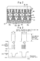
- FIG. 2 is a view for describing the detailed configuration of the fuel addition valve 24 shown in Figure 1 .
- An exhaust passage 18 of the internal combustion engine 10 is divided into branches by an exhaust manifold 20, and each branch thereof connects to an exhaust port 22 of each cylinder.
- the exhaust manifold 20 has branch portions 20a that connect with the exhaust port 22 of each cylinder, and a merging portion 20b after the branch portions 20a of each cylinder have merged.
- the fuel addition valve 24 for injecting (adding) fuel into the exhaust port 22 is installed in the vicinity of the exhaust port 22 in a #1 cylinder of the internal combustion engine 10.
- the #1 cylinder in which the fuel addition valve 24 is installed is referred to as an "addition valve installation cylinder”.
- the exhaust port 22 in each cylinder and the respective branch portions 20a that connect with the respective exhaust ports 22 are defined as an "upstream exhaust passage" from the respective cylinders.
- the internal combustion engine 10 of the present embodiment also includes a turbosupercharger 26.
- the exhaust passage 18 is connected to an exhaust turbine of the turbosupercharger 26.
- An exhaust purification apparatus 28 for purifying exhaust gas is provided on a downstream side of the turbosupercharger 26 in the exhaust passage 18.
- a filter with a catalyst that includes both a function as a storage-reduction type NOx catalyst and a function as a PM filter that traps PM (particulate matter) is provided as the exhaust purification apparatus 28.
- An air/fuel ratio sensor 30 is arranged on a downstream side of the exhaust purification apparatus 28 in the exhaust passage 18 to detect an air/fuel ratio of exhaust gas at that position.
- An air cleaner 34 is provided in the vicinity of an inlet of the intake passage 32 of the internal combustion engine 10. Air that has been drawn in via the air cleaner 34 is compressed by an intake air compressor of the turbosupercharger 26, and thereafter is cooled by an intercooler 36. Intake air that has passed through the intercooler 36 is distributed to an intake port 39 (see Figure 2 ) of each cylinder by an intake manifold 38. An intake throttle valve 40 is arranged between the intercooler 36 and the intake manifold 38. An airflow meter 42 that detects an intake air amount is arranged in the vicinity of the air cleaner 34 on a downstream side thereof.
- the system shown in Figure 1 also includes an intake variable valve operating mechanism 46 that can make valve opening characteristics of an intake valve 44 (see Figure 2 ) of each cylinder variable, and an exhaust variable valve operating mechanism 50 that can make valve opening characteristics of an exhaust valve 48 (see Figure 2 ) of each cylinder variable.
- the intake variable valve operating mechanism 46 has a function (phase varying function) that can vary the opening and closing timings of the intake valve 44 by changing a rotational phase of an intake cam (not shown) with respect to a rotational phase of a crankshaft 52 using hydraulic pressure or an electric motor, and a function (working angle varying function) that can continuously vary the working angle (and lift amount) of the intake valve 44.
- the exhaust variable valve operating mechanism 50 has a phase varying function and a working angle varying function that are the same as those of the intake variable valve operating mechanism 46.
- the intake variable valve operating mechanism 46 includes an intake cam angle sensor 54 for detecting a rotational position (advance amount) of an intake camshaft, and a working angle sensor (not shown) for detecting a working angle of the intake valve 44.
- the exhaust variable valve operating mechanism 50 includes an exhaust cam angle sensor 56, and a working angle sensor (not shown) for detecting a working angle of the exhaust valve 48.
- a crank angle sensor 58 for detecting a crank angle or the number of engine revolutions is arranged in the vicinity of the crankshaft 52.
- the system of the present embodiment includes an ECU (Electronic Control Unit) 60.
- the various sensors and actuators described above are respectively connected to the ECU 60.
- the ECU 60 controls the operating state of the internal combustion engine 10 by driving each actuator according to a predetermined program based on sensor signals and information from the sensors and actuators.
- the above described exhaust purification apparatus 28 includes a storage-reduction type NOx catalyst (hereunder, referred to simply as the "NOx catalyst").
- NOx catalyst a storage-reduction type NOx catalyst
- a configuration is adopted that adds fuel to the exhaust passage 18 using the fuel addition valve 24.
- Added fuel that reaches the NOx catalyst reacts with oxygen contained in exhaust gas in the NOx catalyst and oxidizes. Fuel that remains after most of the oxygen is consumed makes the atmosphere of the NOx catalyst a rich atmosphere, and this surplus fuel also functions as a reducing agent.
- other purposes for performing fuel addition using the fuel addition valve 24 include increasing the temperature of a catalyst such as a NOx catalyst, and combusting and removing PM that has been trapped in a PM filter.
- the fuel addition valve 24 is installed in the exhaust port 22 of the #1 cylinder (addition valve installation cylinder).
- the fuel addition valve 24 is installed in the exhaust port 22 in this manner, to prevent added fuel from adhering to the inner wall of the exhaust port and to ensure the dispersibility of added fuel, it is preferable to perform fuel addition in synchrony with a time period in which exhaust gas is flowing inside the exhaust port 22 of the addition valve installation cylinder, that is, in synchrony with a valve opening period of the exhaust valve 48 of the addition valve installation cylinder.
- Figure 3 is a view for describing a technique for controlling a fuel addition amount using the fuel addition valve 24. More specifically, Figure 3(A) illustrates a situation in which fuel addition is performed using the fuel addition valve 24, and Figure 3(B) shows waveforms of an air/fuel ratio (A/F) of exhaust gas detected by the air/fuel ratio sensor 30 that is arranged downstream of the exhaust purification apparatus 28.
- A/F air/fuel ratio
- the waveform illustrated on the right side in Figure 3(B) represents a case where the oxygen concentration in exhaust gas before starting fuel addition is higher than in the case represented by the waveform illustrated on the left side in Figure 3(B) (that is, the waveform illustrated on the right side represents a case where the exhaust gas prior to the start of fuel addition is lean).
- the fuel addition amount that is required to make the atmosphere of the NOx catalyst a rich atmosphere of the same degree is larger.
- the fuel addition amount per unit time of the fuel addition valve 24 is constant. Consequently, a fuel addition amount for a single time fuel addition is performed (in one cycle) is controlled by taking a fuel addition (injection) period ⁇ a of the fuel addition valve 24 as a parameter.
- the fuel addition period ⁇ a for a single time (in one cycle) is set so as to be a longer period.
- Figure 4 is a view for describing characteristic control in the first embodiment of the present invention in comparison with a conventional configuration. More specifically, Figure 4(A) is a view that illustrates a conventional configuration that is referred to for comparison, and Figure 4(B) is a view that illustrates control of the present embodiment.
- a fuel addition amount that is required for reduction of a NOx catalyst is determined by the exhaust gas flow rate, an oxygen concentration in the exhaust gas ( ⁇ actual A/F), and a reducing agent concentration ( ⁇ target A/F) that it is desired to supply to the NOx catalyst. Further, adjustment of the fuel addition amount using the fuel addition valve 24 is performed by means of the fuel addition period ⁇ a as described above. Therefore, a fuel addition period that is required for reduction of the NOx catalyst (hereunder, referred to simply as the "required addition period ⁇ a”) is also similarly determined by means of the exhaust gas flow rate, the actual A/F, and the target A/F.
- Figure 4(A) illustrates an example of the conventional configuration in which the working angle of the exhaust valve is fixed.
- the valve opening period of the exhaust valve (upper limit of the required addition period ⁇ a) becomes shorter as the number of engine revolutions increases.
- the required addition period ⁇ a lengthens as the number of engine revolutions increases. That is, despite the fact that the required addition period ⁇ a increases as the number of engine revolutions increases, according to the conventional configuration, as shown by the region indicated by hatching in Figure 4(A) , when the number of engine revolutions is high, it is difficult to ensure an adequate amount of added fuel.
- FIG. 5 is a flowchart that illustrates a control routine that the ECU 60 executes in the first embodiment to realize the above described functions.
- the routine shown in Figure 5 first, it is determined whether or not fuel addition is required (step 100). If the result determined in step 100 is that fuel addition is required, the processing of the subsequent steps 102 to 106 is executed in parallel.
- the exhaust gas flow rate is calculated. Calculation of the exhaust gas flow rate can be performed based on, for example, an intake air amount detected by the airflow meter 42.
- an air/fuel ratio of the exhaust gas is detected based on an output of the air/fuel ratio sensor 30.
- a target air/fuel ratio when executing the present fuel addition is determined according to a relation shown in a map or the like that is stored in advance in the ECU 60 (step 106).
- a fuel addition amount required when executing the present fuel addition is calculated based on the exhaust gas flow rate, the air/fuel ratio (actual air/fuel ratio) of the exhaust gas, and the target air/fuel ratio that are acquired in the aforementioned steps 102 to 106 (step 108).
- the required addition period ⁇ a of the fuel addition valve 24 that is required in order to satisfy the calculated required fuel addition amount is calculated (step 110).
- a fuel addition amount Q that the fuel addition valve 24 is capable of adding (injecting) in a unit time is previously stored in the ECU 60.
- the required addition period ⁇ a is calculated by dividing the required fuel addition amount calculated in the aforementioned step 108 by the above described fuel addition amount Q.
- step 112 it is determined whether or not the current valve opening period of the exhaust valve 48 is greater than or equal to the required addition period ⁇ a (step 112).
- the valve opening period of the exhaust valve 48 can be calculated based on the working angle of the exhaust valve 48 and the number of engine revolutions. If it is determined in the aforementioned step 112 that the current valve opening period of the exhaust valve 48 is greater than or equal to the required addition period ⁇ a, it can be determined that fuel addition that can ensure the required fuel addition amount can be performed using the setting of the current working angle of the exhaust valve 48. Therefore, in this case, fuel addition is executed immediately using the fuel addition valve 24 (step 114).
- step 116 the required working angle of the exhaust valve 48 is calculated (step 116). More specifically, in step 116, the required working angle of the exhaust valve 48 is set so that the higher the number of engine revolutions is at the time of fuel addition, the larger the required working angle of the exhaust valve 48 becomes.
- step 118 At least either one of an operation to advance the opening timing of the exhaust valve 48 and an operation to retard the closing timing of the exhaust valve 48 is executed (step 118).
- fuel addition is executed using the fuel addition valve 24 (step 114).
- the valve opening period of the exhaust valve 48 can be extended by increasing the working angle of the exhaust valve 48. It is thereby possible to extend the period in which the fuel addition valve 24 can inject fuel (upper limit of the required addition period ⁇ a). Thus, a region in which addition of a required amount of fuel is possible can be widened. Consequently, since the operating region in which the atmosphere of the NOx catalyst can be made a sufficiently rich atmosphere can be widened, it is possible to suppress a deterioration in the exhaust emissions.
- fuel addition execution means according to the above described first aspect of the present invention is realized by the ECU 60 executing the processing of the above described step 114
- reconquired addition period acquisition means according to the first aspect of the present invention is realized by the ECU 60 executing the processing of the above described step 110
- exhaust working angle adjustment means according to the first aspect of the present invention is realized by the ECU 60 executing the processing of the above described steps 112, 116, and 118.
- number of revolutions acquisition means according to the above described third aspect of the present invention is realized by the ECU 60 acquiring the number of engine revolutions based on the output of the crank angle sensor 58.
- FIG. 6 is a view for describing characteristic control that is executed according to the second embodiment of the present invention.
- a fuel flow rate that can be injected fuel addition amount Q per unit time
- an injection period (required addition period) ⁇ a that is required to add fuel of a predetermined amount increases in comparison to when using the fuel addition valve 24 that can inject fuel at a standard fuel flow rate. Consequently, as shown in Figure 5 , when using the fuel addition valve 24 in which the fuel flow rate that can be injected is low, the upper limit of the number of engine revolutions at which the required addition period ⁇ a can be secured decreases.
- the working angle of the exhaust valve 48 is increased using at least either one of an operation to advance the opening timing of the exhaust valve 48 and an operation to retard the closing timing of the exhaust valve 48.
- ⁇ Q characteristics that are established between the fuel addition period (current conduction period) ⁇ of the fuel addition valve 24 and the fuel addition amount Q per unit time that is injected from the fuel addition valve 24 when power is applied are previously measured and stored in the ECU 60.
- the ECU 60 increases the working angle of the exhaust valve 48 so that a fuel addition region is secured that is equivalent to a time of using the fuel addition valve 24 that can perform injection at a standard fuel flow rate.
- a favorable fuel addition region can be secured even when the fuel flow rate of the fuel addition valve 24 that is actually mounted in the internal combustion engine 10 is less than the fuel flow rate of the standard fuel addition valve 24.
- FIG. 7 a third embodiment 3 of the present invention is described referring to Figure 7 to Figure 10 .
- the system of the present embodiment can be realized using the hardware configuration shown in Figure 1 by causing the ECU 60 to execute the routines shown in Figure 9 and Figure 10 , which are described later, instead of the routine shown in Figure 5 .
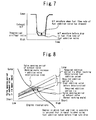
- Figure 7 is a view that illustrates the influence of a drop in the fuel flow rate on a waveform of an air/fuel ratio at a time of fuel addition by the fuel addition valve 24.
- the flow rate of fuel (fuel addition amount Q per unit time) that is injected by the fuel addition valve 24 may drop due to deterioration over time or adherence of deposits.
- the air/fuel ratio of the exhaust gas becomes lean compared to the air/fuel ratio before the drop in the fuel flow rate (corresponds to the target air/fuel ratio). Consequently, it is not possible to adequately control the atmosphere of the NOx catalyst to generate an intended rich atmosphere.
- a configuration is adopted so as to periodically learn a deterioration in the fuel addition valve 24 (the aforementioned drop in the fuel flow rate) based on the air/fuel ratio of exhaust gas when performing fuel addition.
- this learning is referred to as the "addition valve deterioration learning”.
- the existence or non-existence of a drop (deterioration) in the fuel flow rate of the fuel addition valve 24 is determined based on a difference between an air/fuel ratio of exhaust gas that is detected by the air/fuel ratio sensor 30 when performing fuel addition and an air/fuel ratio of exhaust gas when performing fuel addition in a state in which the fuel flow rate has not dropped (that is, a target air/fuel ratio). If it is determined that the fuel flow rate of the fuel addition valve 24 has dropped, the magnitude of the drop (drop amount) in the fuel flow rate is calculated based on the above described difference in the air/fuel ratios, and the calculated magnitude of the drop in the fuel flow rate is recorded as an addition valve deterioration learning value in the ECU 60. The addition valve deterioration learning value is updated sequentially as learning proceeds. Furthermore, the required addition period ⁇ a is corrected based on the recorded addition valve deterioration learning value.
- Figure 8 is a view for describing characteristic control according to the third embodiment 3 of the present invention.
- the control described hereunder is executed after executing an addition valve deterioration learning operation as described above. More specifically, as shown in Figure 8 , when the required addition period ⁇ a that has been corrected based on the addition valve deterioration learning value is longer than a valve opening period of the exhaust valve 48 when performing fuel addition, the valve opening period of the exhaust valve 48 is extended by increasing the working angle of the exhaust valve 48 so that a region in which fuel addition is possible that is equivalent to before the drop in the fuel flow rate is secured.
- FIG 9 is a flowchart of a routine that the ECU 60 executes according to the third embodiment to realize the above described addition valve deterioration learning.
- the routine illustrated in Figure 9 first, it is determined whether or not a fuel addition operation is being executed (step 200). If the result determined in step 200 is that a fuel addition operation is being executed, the air/fuel ratio of exhaust gas downstream of the exhaust purification apparatus 28 is detected using the air/fuel ratio sensor 30 (step 202).
- a difference between the air/fuel ratio of the exhaust gas detected in the aforementioned step 202 and an air/fuel ratio of exhaust gas when performing a fuel addition operation in a state in which the fuel flow rate has not dropped is calculated (step 204).
- step 208 If the result determined in the aforementioned step 206 is that the fuel flow rate of the fuel addition valve 24 has dropped, after the magnitude of the drop (drop amount) in the fuel flow rate is calculated based on the above described difference between the exhaust gas air/fuel ratios, the magnitude of the drop is recorded as the addition valve deterioration learning value (step 208).
- Figure 10 is a flowchart that illustrates a control routine that is executed when performing a fuel addition operation according to the third embodiment of the present invention.
- steps that are the same as steps in the flowchart illustrated in Figure 5 according to the first embodiment are denoted by the same reference numbers, and a description of those steps is omitted or simplified below.
- a required addition period ⁇ a' in which the above described addition valve deterioration learning value has been reflected is calculated (step 300). More specifically, in step 300, the higher that the addition valve deterioration learning value (magnitude of drop in the fuel flow rate) is, the greater the value that is calculated for the required addition period ⁇ a' relative to the required addition period ⁇ a in a case where the addition valve deterioration learning value is not reflected (this value can be calculated by the technique in step 110 that is described above).
- step 302 it is determined whether or not the current valve opening period of the exhaust valve 48 is equal to or greater than the aforementioned required addition period ⁇ a' in which the addition valve deterioration learning value has been reflected (step 302). If the result determined in step 302 is affirmative, since it can be determined that fuel addition that can ensure the required fuel addition amount can be performed with the current setting of the working angle of the exhaust valve 48, a fuel addition operation is immediately executed using the fuel addition valve 24 (step 304).
- step 302 determines whether the required addition period ⁇ a' after the above described learning operation is longer than the current valve opening period of the exhaust valve 48.
- the working angle of the exhaust valve 48 is increased so as to make the valve opening period of the exhaust valve 48 equal to or greater than the required addition period ⁇ a' after the above described learning operation (step 306).
- a drop in the flow rate of fuel that is added by the fuel addition valve 24 can be diagnosed based on a difference between the actual air/fuel ratio of exhaust gas when adding fuel and the target air/fuel ratio. Further, when it is determined that the fuel flow rate of the fuel addition valve 24 has dropped, after calculating the magnitude of the drop in the fuel flow rate, the calculated magnitude of the drop is recorded as the addition valve deterioration learning value.
- the required addition period ⁇ a' in which the addition valve deterioration learning value is reflected is calculated. Further, when it is determined that the required addition period ⁇ a' after the above described learning operation is longer than the current valve opening period of the exhaust valve 48, the working angle of the exhaust valve 48 is increased so that the valve opening period of the exhaust valve 48 becomes equal to or greater than the required addition period ⁇ a' after the above described learning operation.
- the working angle of the exhaust valve 48 is increased so that the valve opening period of the exhaust valve 48 becomes equal to or greater than the required addition period ⁇ a' after the above described learning operation.
- air/fuel ratio acquisition means according to the above described fourth or sixth aspect of the present invention is realized by the ECU 60 acquiring an air/fuel ratio of exhaust gas based on an output of the air/fuel ratio sensor 30, and "addition valve performance determination means” according to the fourth aspect of the present invention is realized by the ECU 60 executing the processing of the above described step 206.
- flow rate drop amount calculation means according to the sixth aspect of the present invention is realized by the ECU 60 executing the processing of the above described step 208
- “required addition period correction means” according to the sixth aspect of the present invention is realized by the ECU 60 executing the processing of the above described step 300.
- FIG. 11 a fourth embodiment of the present invention is described referring to Figure 11 .
- the system of the present embodiment can be realized using the hardware configuration shown in Figure 1 by causing the ECU 60 to execute a routine illustrated in Figure 11 , which is described later, instead of the routine shown in Figure 5 .
- a configuration is adopted such that, when it is determined that the required addition period ⁇ a is longer than the current valve opening period of the exhaust valve 48, the working angle of the exhaust valve 48 is increased so that the valve opening period of the exhaust valve 48 becomes equal to or greater than the required addition period ⁇ a. According to this technique, a region in which addition of a required amount of fuel is possible can be widened by increasing the fuel amount that can be added.
- a region in which addition of a required amount of fuel is possible can also be widened by changing the valve opening characteristics of the intake valve 44 so as to reduce the intake air amount. More specifically, when the intake air amount is reduced by changing the valve opening characteristics of the intake valve 44, the air/fuel ratio of the exhaust gas becomes a richer value, and the exhaust gas flow rate itself also decreases. Therefore, the amount of oxygen in the exhaust gas decreases, and the fuel addition amount that is required to make the atmosphere of the NOx catalyst a rich atmosphere decreases. As a result, since the required addition period ⁇ a need only be a short period, it is possible to widen the region in which addition of a required amount of fuel is possible.
- a configuration is adopted so that, when it is determined that the required addition period ⁇ a is longer than the current valve opening period of the exhaust valve 48, it is determined which of the above described two adjustment techniques (that is, adjustment of the working angle of the exhaust valve 48, and adjustment of the valve opening characteristics of the intake valve 44) is more advantageous in terms of fuel consumption in the current operating state of the internal combustion engine 10 for ensuring the required addition amount of the fuel addition valve 24. Thereafter, according to the present embodiment, control is performed so that the valve opening period of the exhaust valve 48 becomes equal to or greater than the required addition period ⁇ a using the adjustment technique that is determined as being more advantageous in terms of fuel consumption.
- Figure 11 is a flowchart illustrating a control routine that the ECU 60 executes according to the fourth embodiment to realize that above described functions.
- steps that are the same as steps in the flowchart illustrated in Figure 5 according to the first embodiment are denoted by the same reference numbers, and a description of those steps is omitted or simplified below.
- step 112 if it is determined that the result determined in step 112 is negative (that is, if it is determined that the required addition period ⁇ a is longer than the current valve opening period of the exhaust valve 48), it is next determined whether or not, in the current operating state of the internal combustion engine 10, adjusting the working angle of the exhaust valve 48 is more advantageous in terms of fuel consumption than adjusting the valve opening characteristics of the intake valve 44 for ensuring the required addition amount of the fuel addition valve 24 (step 400).
- Which operation among an operation to adjust the working angle of the exhaust valve 48 and an operation to adjust the opening and closing timings of the intake valve 44 is advantageous in terms of fuel consumption differs according to the operating state of the internal combustion engine 10.
- the ECU 60 includes therein a map (not illustrated) that specifies, based on experiment or simulation or the like that has been carried out in advance, which of the above described two adjustment techniques is more advantageous in terms of fuel consumption according to the relation between individual operating states of the internal combustion engine 10 and a required addition amount of the fuel addition valve 24.
- the determination in the aforementioned step 400 is performed utilizing the relation specified in the above described map.
- a configuration may also be adopted that, instead of the aforementioned technique, for example, selects the adjustment technique that is more advantageous in terms of fuel consumption after calculating which of the two adjustment techniques is more advantageous in terms of fuel consumption using the actual machine.
- control is executed so that the valve opening period of the exhaust valve 48 becomes equal to or greater than the required addition period ⁇ a by adjusting the working angle of the exhaust valve 48 (step 402).
- control is executed so that the valve opening period of the exhaust valve 48 becomes equal to or greater than the required addition period ⁇ a by adjusting the valve opening characteristics of the intake valve 44 so that the intake air amount decreases (step 404).
- step 404 as a specific technique for adjusting the valve opening characteristics of the intake valve 44 to decrease the intake air amount, for example, a technique can be used that reduces the working angle of the intake valve 44 using at least one of an operation to retard the opening timing and an operation to advance the closing timing.
- an adjustment technique is selected that is more advantageous in terms of fuel consumption in the current operating state of the internal combustion engine 10 for ensuring the required addition amount of the fuel addition valve 24.
- control is executed using the selected adjustment technique so that the valve opening period of the exhaust valve 48 becomes equal to or greater than the required addition period ⁇ a. It is thus possible to widen a region in which addition of a required amount of fuel is possible while suppressing fuel consumption.
- a configuration is adopted so that, when it is determined that the required addition period ⁇ a is longer than the current valve opening period of the exhaust valve 48 when performing a fuel addition operation, among an adjustment technique that adjusts the working angle of the exhaust valve 48 and an adjustment technique that adjusts the valve opening characteristics of the intake valve 44, an adjustment technique is selected that is more advantageous in terms of fuel consumption in the current operating state of the internal combustion engine 10 for ensuring the required addition amount of the fuel addition valve 24.
- the present invention is not limited to this configuration. For example, the following configuration may also be adopted.
- a configuration may be adopted such that, when a required fuel addition amount is equal to or greater than a predetermined amount when performing a fuel addition operation (more specifically, when it is determined that the required addition period ⁇ a is longer than the current valve opening period of the exhaust valve 48), as well as adjusting the working angle of the exhaust valve 48, the valve opening characteristics of the intake valve 44 are controlled so as to reduce the intake air amount.
- air amount adjustment means in the aforementioned seventh aspect of the present invention is realized by the ECU 60 adjusting the working angle of the intake valve 44 using the intake variable valve operating mechanism 46
- selection means in the seventh aspect of the present invention is realized by the ECU 60 executing the processing of the above described step 400
- adjustment execution means in the seventh aspect of the present invention is realized by the ECU 60 executing the processing of the above described step 402 or 404.
- the installation location of the fuel addition valve according to the present invention is not limited to an exhaust port as long as the installation location of the fuel addition valve is in an upstream exhaust passage as defined herein (in the configuration shown in Figure 2 , the exhaust port 22 of each cylinder and the branch portion 20a of the exhaust manifold 20 of each cylinder). Further, the fuel addition valve according to the present invention may also be installed in a plurality of cylinders.
Landscapes
- Engineering & Computer Science (AREA)
- Chemical & Material Sciences (AREA)
- Combustion & Propulsion (AREA)
- Mechanical Engineering (AREA)
- General Engineering & Computer Science (AREA)
- Chemical Kinetics & Catalysis (AREA)
- Output Control And Ontrol Of Special Type Engine (AREA)
- Exhaust Gas After Treatment (AREA)
Abstract
Description
- The present invention relates to a control apparatus for an internal combustion engine.
- A conventional exhaust purification apparatus for an internal combustion engine that is equipped with a fuel addition valve in an exhaust port is disclosed, for example, in
Patent Document 1. InPatent Document 1, a technique is described in which fuel addition using a fuel addition valve is executed in synchrony with a valve opening period of an exhaust valve provided in a cylinder in which the fuel addition valve is installed.
The applicant is aware of the following documents, which include the above described document, as documents related to the present invention. -
- Patent Document 1: Japanese Laid-open Patent Application Publication No.
2001-280125 - Patent Document 2: Japanese Laid-open Patent Application Publication No.
2008-38825 - Patent Document 3: Japanese Laid-open Patent Application Publication No.
2008-69657 - In the above described conventional internal combustion engine in which a working angle of an exhaust valve is fixed, a valve opening period of the exhaust valve shortens as the number of engine revolutions increases. On the other hand, since an exhaust gas flow rate fundamentally increases as the number of engine revolutions increases, a fuel addition amount that is required to maintain an exhaust purification catalyst under an atmosphere in which there is a rich air/fuel ratio increases. That is, despite the fact that the required fuel addition amount increases as the number of engine revolutions increases, according to the configuration of the conventional internal combustion engine that is described above, when the number of engine revolutions is high, it is difficult to ensure an adequate amount of added fuel.
- The present invention has been conceived to solve the above described problem, and an object of the present invention is to provide a control apparatus for an internal combustion engine that makes it possible to more adequately secure a required addition period of fuel that is added by a fuel addition valve, regardless of the operating state of the internal combustion engine.
- A first aspect of the present invention is a control apparatus for an internal combustion engine, comprising:
- a fuel addition valve that is installed in at least one cylinder of an internal combustion engine in an upstream exhaust passage on a side that is further upstream than a merging portion with an upstream exhaust passage from another cylinder, and that is capable of adding fuel into the upstream exhaust passage;
- an exhaust variable valve operating mechanism that makes a working angle of an exhaust valve variable;
- fuel addition execution means that executes fuel addition using the fuel addition valve in synchrony with a valve opening period of the exhaust valve that is provided in a cylinder in which the fuel addition valve is installed;
- required addition period acquisition means that acquires a required addition period of fuel using the fuel addition valve; and
- exhaust working angle adjustment means that adjusts a working angle of the exhaust valve using the exhaust variable valve operating mechanism in accordance with the required addition period.
- A second aspect of the present invention is the control apparatus for an internal combustion engine according to the first aspect of the present invention,
wherein when the required addition period is longer than a valve opening period of the exhaust valve, the exhaust working angle adjustment means increases a working angle of the exhaust valve. - A third aspect of the present invention is the control apparatus for an internal combustion engine according to the first or second aspect of the present invention, further comprising:
- number of revolutions acquisition means that acquires a number of engine revolutions;
- wherein the higher that a number of engine revolutions is, the greater a degree to which the exhaust working angle adjustment means increases a working angle of the exhaust valve.
- A fourth aspect of the present invention is the control apparatus for an internal combustion engine according to any one of the first to third aspects of the present invention, further comprising:
- air/fuel ratio acquisition means that is installed in an exhaust passage on a side that is further downstream than the fuel addition valve, and that acquires an air/fuel ratio of exhaust gas; and
- addition valve performance determination means that, when an air/fuel ratio of exhaust gas that is acquired by the air/fuel ratio acquisition means when performing fuel addition using the fuel addition valve is leaner than a target air/fuel ratio, determines that a flow rate of fuel that is added by the fuel addition valve has dropped.
- A fifth aspect of the present invention is the control apparatus for an internal combustion engine according to the fourth aspect of the present invention,
wherein when the addition valve performance determination means determines that a flow rate of fuel that is added by the fuel addition valve has dropped, the exhaust working angle adjustment means increases a working angle of the exhaust valve. - A sixth aspect of the present invention is the control apparatus for an internal combustion engine according to any one of the first to third aspects of the present invention, further comprising:
- air/fuel ratio acquisition means that is installed in an exhaust passage on a side that is further downstream that the fuel addition valve, and that acquires an air/fuel ratio of exhaust gas;
- flow rate drop amount calculation means that, when performing fuel addition using the fuel addition valve, calculates an amount of a drop in a flow rate of fuel that is added by the fuel addition valve based on a difference between an air/fuel ratio of exhaust gas that is acquired by the air/fuel ratio acquisition means and a target air/fuel ratio; and
- required addition period correction means that corrects the required addition period based on the amount of the drop in the flow rate.
- A seventh aspect of the present invention is the control apparatus for an internal combustion engine according to any one of the first to sixth aspects of the present invention, further comprising:
- an intake variable valve operating mechanism that makes valve opening characteristics of an intake valve variable;
- air amount adjustment means that adjusts an air amount that is drawn into a cylinder by changing valve opening characteristics of the intake valve using the intake variable valve operating mechanism;
- selection means that, when the required addition period is longer than a valve opening period of the exhaust valve, among an adjustment technique that adjusts a working angle of the exhaust valve by means of the exhaust working angle adjustment means and an adjustment technique that adjusts the air amount by means of the air amount adjustment means, selects an adjustment technique that is more advantageous in terms of fuel consumption of the internal combustion engine for ensuring a required addition amount by means of the fuel addition valve; and
- adjustment execution means that executes an adjustment using an adjustment technique that is selected by the selection means so that a state is obtained in which a valve opening period of the exhaust valve becomes equal to or greater than the required addition.
- According to the first aspect of the present invention, by including means that adjusts a working angle of an exhaust valve in accordance with a required addition period of fuel that is added using a fuel addition valve, when there is a high number of engine revolutions or the like, the valve opening period of the exhaust valve can be extended by increasing the working angle of the exhaust valve as the need arises. Thus, a required addition period can be more adequately secured regardless of the operating state of the internal combustion engine.
- According to the second aspect of the present invention, since the valve opening period of the exhaust valve can be extended by increasing the working angle of the exhaust valve, a required addition period can be more adequately secured.
- According to the third aspect of the present invention, for a region in which the number of engine revolutions is high and it is difficult to secure a required addition period because the valve opening period of the exhaust valve is short, it is possible to widen a region in which addition of a required amount of fuel is possible.
- According to the fourth aspect of the present invention, it is possible to diagnose a drop in the flow rate of fuel that is added by the fuel addition valve based on the actual air/fuel ratio of exhaust gas and the target air/fuel ratio when adding fuel.
- According to the fifth aspect of the present invention, to compensate for a drop in the fuel flow rate of the fuel addition valve, a region in which fuel addition is possible can be secured that is equivalent to before the drop in the fuel flow rate by increasing the working angle of the exhaust valve.
- According to the sixth aspect of the present invention, a required addition period is corrected based on an amount of a drop in the flow rate of fuel that is added by the fuel addition valve. As a result, the working angle of the exhaust valve is adjusted in accordance with a required addition period after correction that reflects the influence of the aforementioned flow rate drop. Therefore, to compensate for a drop in the fuel flow rate of the fuel addition valve, a region in which fuel addition is possible can be secured that is equivalent to before the drop in the fuel flow rate by increasing the working angle of the exhaust valve.
- According to the seventh aspect of the present invention it is possible to widen a region in which addition of a required amount of fuel is possible while suppressing fuel consumption.
-
-
Figure 1 is a diagram for describing the system configuration according to a first embodiment of the present invention; -
Figure 2 is a view for describing the detailed configuration of a fuel addition valve shown inFigure 1 ; -
Figure 3 is a view for describing a technique for controlling a fuel addition amount using the fuel addition valve; -
Figure 4 is a view for describing characteristic control in the first embodiment of the present invention in comparison with a conventional configuration; -
Figure 5 is a flowchart of a routine that is executed in the first embodiment of the present invention; -
Figure 6 is a view for describing characteristic control that is executed according to a second embodiment of the present invention; -
Figure 7 is a view that illustrates the influence of a drop in the fuel flow rate on a waveform of an air/fuel ratio at a time of fuel addition by the fuel addition valve; -
Figure 8 is a view for describing characteristic control according to a third embodiment of the present invention; -
Figure 9 is a flowchart of a routine that is executed in the third embodiment of the present invention to realize an addition valve deterioration learning; -
Figure 10 is a flowchart that illustrates a control routine that is executed when performing a fuel addition operation according to the third embodiment of the present invention; and -
Figure 11 is a flowchart of a routine that is executed in a fourth embodiment of the present invention. -
Figure 1 is a diagram for describing the system configuration according to a first embodiment of the present invention. The system shown inFigure 1 includes a compression ignition-typeinternal combustion engine 10. In this case, as an example of a compression ignition-type internal combustion engine, it is assumed that theinternal combustion engine 10 is an in-line four-cylinder diesel engine. - Each cylinder of the
internal combustion engine 10 is provided with aninjector 12 that injects fuel directly into the cylinder. Theinjectors 12 of the respective cylinders are connected to acommon rail 14. Fuel stored in an unshown fuel tank is high-pressure fuel that is pressurized to a predetermined fuel pressure by asupply pump 16. Fuel that is retained inside thecommon rail 14 is supplied to eachinjector 12. -
Figure 2 is a view for describing the detailed configuration of thefuel addition valve 24 shown inFigure 1 . Anexhaust passage 18 of theinternal combustion engine 10 is divided into branches by anexhaust manifold 20, and each branch thereof connects to anexhaust port 22 of each cylinder. Theexhaust manifold 20 hasbranch portions 20a that connect with theexhaust port 22 of each cylinder, and a mergingportion 20b after thebranch portions 20a of each cylinder have merged. - As shown in
Figure 1 andFigure 2 , thefuel addition valve 24 for injecting (adding) fuel into theexhaust port 22 is installed in the vicinity of theexhaust port 22 in a #1 cylinder of theinternal combustion engine 10. Hereunder, the #1 cylinder in which thefuel addition valve 24 is installed is referred to as an "addition valve installation cylinder". Furthermore, herein, theexhaust port 22 in each cylinder and therespective branch portions 20a that connect with therespective exhaust ports 22 are defined as an "upstream exhaust passage" from the respective cylinders. - As shown in
Figure 1 , theinternal combustion engine 10 of the present embodiment also includes aturbosupercharger 26. Theexhaust passage 18 is connected to an exhaust turbine of theturbosupercharger 26. Anexhaust purification apparatus 28 for purifying exhaust gas is provided on a downstream side of theturbosupercharger 26 in theexhaust passage 18. In this case, a filter with a catalyst that includes both a function as a storage-reduction type NOx catalyst and a function as a PM filter that traps PM (particulate matter) is provided as theexhaust purification apparatus 28. An air/fuel ratio sensor 30 is arranged on a downstream side of theexhaust purification apparatus 28 in theexhaust passage 18 to detect an air/fuel ratio of exhaust gas at that position. - An
air cleaner 34 is provided in the vicinity of an inlet of theintake passage 32 of theinternal combustion engine 10. Air that has been drawn in via theair cleaner 34 is compressed by an intake air compressor of theturbosupercharger 26, and thereafter is cooled by anintercooler 36. Intake air that has passed through theintercooler 36 is distributed to an intake port 39 (seeFigure 2 ) of each cylinder by anintake manifold 38. Anintake throttle valve 40 is arranged between theintercooler 36 and theintake manifold 38. Anairflow meter 42 that detects an intake air amount is arranged in the vicinity of theair cleaner 34 on a downstream side thereof. - The system shown in
Figure 1 also includes an intake variablevalve operating mechanism 46 that can make valve opening characteristics of an intake valve 44 (seeFigure 2 ) of each cylinder variable, and an exhaust variablevalve operating mechanism 50 that can make valve opening characteristics of an exhaust valve 48 (seeFigure 2 ) of each cylinder variable. More specifically, in this case the intake variablevalve operating mechanism 46 has a function (phase varying function) that can vary the opening and closing timings of theintake valve 44 by changing a rotational phase of an intake cam (not shown) with respect to a rotational phase of acrankshaft 52 using hydraulic pressure or an electric motor, and a function (working angle varying function) that can continuously vary the working angle (and lift amount) of theintake valve 44. - The exhaust variable
valve operating mechanism 50 has a phase varying function and a working angle varying function that are the same as those of the intake variablevalve operating mechanism 46. Further, the intake variablevalve operating mechanism 46 includes an intakecam angle sensor 54 for detecting a rotational position (advance amount) of an intake camshaft, and a working angle sensor (not shown) for detecting a working angle of theintake valve 44. Likewise, the exhaust variablevalve operating mechanism 50 includes an exhaustcam angle sensor 56, and a working angle sensor (not shown) for detecting a working angle of theexhaust valve 48. In addition, acrank angle sensor 58 for detecting a crank angle or the number of engine revolutions is arranged in the vicinity of thecrankshaft 52. - The system of the present embodiment includes an ECU (Electronic Control Unit) 60. The various sensors and actuators described above are respectively connected to the
ECU 60. TheECU 60 controls the operating state of theinternal combustion engine 10 by driving each actuator according to a predetermined program based on sensor signals and information from the sensors and actuators. - The above described
exhaust purification apparatus 28 includes a storage-reduction type NOx catalyst (hereunder, referred to simply as the "NOx catalyst"). In order to release/reduce NOx that is stored in the NOx catalyst, it is necessary to supply exhaust gas having a rich air/fuel ratio to the NOx catalyst at predetermined time intervals. For this purpose, according to the present embodiment a configuration is adopted that adds fuel to theexhaust passage 18 using thefuel addition valve 24. Added fuel that reaches the NOx catalyst reacts with oxygen contained in exhaust gas in the NOx catalyst and oxidizes. Fuel that remains after most of the oxygen is consumed makes the atmosphere of the NOx catalyst a rich atmosphere, and this surplus fuel also functions as a reducing agent. In this connection, in addition to the above described purpose of supplying a reducing agent to the NOx catalyst, other purposes for performing fuel addition using thefuel addition valve 24 include increasing the temperature of a catalyst such as a NOx catalyst, and combusting and removing PM that has been trapped in a PM filter. - According to the present embodiment, from the viewpoint of the arrangement of fuel piping and the like, the
fuel addition valve 24 is installed in theexhaust port 22 of the #1 cylinder (addition valve installation cylinder). When thefuel addition valve 24 is installed in theexhaust port 22 in this manner, to prevent added fuel from adhering to the inner wall of the exhaust port and to ensure the dispersibility of added fuel, it is preferable to perform fuel addition in synchrony with a time period in which exhaust gas is flowing inside theexhaust port 22 of the addition valve installation cylinder, that is, in synchrony with a valve opening period of theexhaust valve 48 of the addition valve installation cylinder. -
Figure 3 is a view for describing a technique for controlling a fuel addition amount using thefuel addition valve 24. More specifically,Figure 3(A) illustrates a situation in which fuel addition is performed using thefuel addition valve 24, andFigure 3(B) shows waveforms of an air/fuel ratio (A/F) of exhaust gas detected by the air/fuel ratio sensor 30 that is arranged downstream of theexhaust purification apparatus 28. - According to the present embodiment, when performing fuel addition in synchrony with a valve opening period of the
exhaust valve 48 of the addition valve installation cylinder as described above, in order to secure a longer period in which the atmosphere of the NOx catalyst is made a rich atmosphere, as shown inFigure 3(A) , execution of the fuel addition operation is divided over a plurality of cycles of theinternal combustion engine 10. More specifically, a period in which the atmosphere of the NOx catalyst is made a rich atmosphere is controlled by means of the number of times that fuel addition is performed using thefuel addition valve 24. As a result, in a waveform on the right side inFigure 3(B) , the air/fuel ratio of exhaust gas is controlled so as to be in a rich state for a longer period compared to a waveform on the left side inFigure 3(B) . - The waveform illustrated on the right side in
Figure 3(B) represents a case where the oxygen concentration in exhaust gas before starting fuel addition is higher than in the case represented by the waveform illustrated on the left side inFigure 3(B) (that is, the waveform illustrated on the right side represents a case where the exhaust gas prior to the start of fuel addition is lean). When the exhaust gas prior to the start of fuel addition is leaner, the fuel addition amount that is required to make the atmosphere of the NOx catalyst a rich atmosphere of the same degree is larger. However, the fuel addition amount per unit time of thefuel addition valve 24 is constant. Consequently, a fuel addition amount for a single time fuel addition is performed (in one cycle) is controlled by taking a fuel addition (injection) period τa of thefuel addition valve 24 as a parameter. Accordingly, in a case where the exhaust gas before starting fuel addition is leaner (the case represented by the waveform on the right side inFigure 3 ), as shown inFigure 3 , the fuel addition period τa for a single time (in one cycle) is set so as to be a longer period. -
Figure 4 is a view for describing characteristic control in the first embodiment of the present invention in comparison with a conventional configuration. More specifically,Figure 4(A) is a view that illustrates a conventional configuration that is referred to for comparison, andFigure 4(B) is a view that illustrates control of the present embodiment. - A fuel addition amount that is required for reduction of a NOx catalyst is determined by the exhaust gas flow rate, an oxygen concentration in the exhaust gas (≈ actual A/F), and a reducing agent concentration (≈ target A/F) that it is desired to supply to the NOx catalyst. Further, adjustment of the fuel addition amount using the
fuel addition valve 24 is performed by means of the fuel addition period τa as described above. Therefore, a fuel addition period that is required for reduction of the NOx catalyst (hereunder, referred to simply as the "required addition period τa") is also similarly determined by means of the exhaust gas flow rate, the actual A/F, and the target A/F. - When the relation between the required addition period τa that is determined as described above and the number of engine revolutions is represented diagrammatically, a region having a width as shown in
Figure 4 is obtained. Fundamentally, the exhaust gas flow rate increases together with an increase in the number of engine revolutions. Therefore, as shown inFigure 4 , the higher that the number of engine revolutions is, the longer that the required addition period τa becomes. Further, when performing fuel addition in synchrony with the valve opening period of theexhaust valve 48 of the addition valve installation cylinder as described above, the valve opening period of theexhaust valve 48 of the addition valve installation cylinder is the upper limit of the fuel addition period τa. -
Figure 4(A) illustrates an example of the conventional configuration in which the working angle of the exhaust valve is fixed. When the working angle of the exhaust valve is fixed, as shown inFigure 4(A) , the valve opening period of the exhaust valve (upper limit of the required addition period τa) becomes shorter as the number of engine revolutions increases. On the other hand, as described above, the required addition period τa lengthens as the number of engine revolutions increases. That is, despite the fact that the required addition period τa increases as the number of engine revolutions increases, according to the conventional configuration, as shown by the region indicated by hatching inFigure 4(A) , when the number of engine revolutions is high, it is difficult to ensure an adequate amount of added fuel. - Therefore, according to the present embodiment, as shown in
Figure 4(B) , when the required addition period τa is longer than the valve opening period of theexhaust valve 48, the working angle of theexhaust valve 48 of the addition valve installation cylinder is increased using the exhaust variablevalve operating mechanism 50. More specifically, a configuration is adopted that increases the working angle of theexhaust valve 48 of the addition valve installation cylinder in accordance with an increase in the number of engine revolutions. Thus, in a region with a high number of engine revolutions in which it is difficult to secure the required addition period τa because the valve opening period of theexhaust valve 48 is short, a period in which thefuel addition valve 24 can inject fuel (upper limit of the required addition period τa) can be extended. Therefore, as shown inFigure 4(B) , it is possible to widen a region in which a required amount of fuel can be added. -
Figure 5 is a flowchart that illustrates a control routine that theECU 60 executes in the first embodiment to realize the above described functions.
In the routine shown inFigure 5 , first, it is determined whether or not fuel addition is required (step 100). If the result determined instep 100 is that fuel addition is required, the processing of thesubsequent steps 102 to 106 is executed in parallel. - In the
aforementioned step 102, the exhaust gas flow rate is calculated. Calculation of the exhaust gas flow rate can be performed based on, for example, an intake air amount detected by theairflow meter 42. In theaforementioned step 104, an air/fuel ratio of the exhaust gas is detected based on an output of the air/fuel ratio sensor 30. Further, in theaforementioned step 106, a target air/fuel ratio when executing the present fuel addition is determined according to a relation shown in a map or the like that is stored in advance in the ECU 60 (step 106). - Next, a fuel addition amount required when executing the present fuel addition is calculated based on the exhaust gas flow rate, the air/fuel ratio (actual air/fuel ratio) of the exhaust gas, and the target air/fuel ratio that are acquired in the
aforementioned steps 102 to 106 (step 108). Subsequently, the required addition period τa of thefuel addition valve 24 that is required in order to satisfy the calculated required fuel addition amount is calculated (step 110). A fuel addition amount Q that thefuel addition valve 24 is capable of adding (injecting) in a unit time is previously stored in theECU 60. In theaforementioned step 110, the required addition period τa is calculated by dividing the required fuel addition amount calculated in theaforementioned step 108 by the above described fuel addition amount Q. - Next, it is determined whether or not the current valve opening period of the
exhaust valve 48 is greater than or equal to the required addition period τa (step 112). The valve opening period of theexhaust valve 48 can be calculated based on the working angle of theexhaust valve 48 and the number of engine revolutions. If it is determined in theaforementioned step 112 that the current valve opening period of theexhaust valve 48 is greater than or equal to the required addition period τa, it can be determined that fuel addition that can ensure the required fuel addition amount can be performed using the setting of the current working angle of theexhaust valve 48. Therefore, in this case, fuel addition is executed immediately using the fuel addition valve 24 (step 114). - In contrast, if the result determined in the
aforementioned step 112 is negative, that is, if it is determined that the required addition period τa is longer than the current valve opening period of theexhaust valve 48, the required working angle of theexhaust valve 48 is calculated (step 116). More specifically, instep 116, the required working angle of theexhaust valve 48 is set so that the higher the number of engine revolutions is at the time of fuel addition, the larger the required working angle of theexhaust valve 48 becomes. - Subsequently, to obtain the required working angle of the
exhaust valve 48 that is calculated in theaforementioned step 116, at least either one of an operation to advance the opening timing of theexhaust valve 48 and an operation to retard the closing timing of theexhaust valve 48 is executed (step 118). After adjusting the working angle of theexhaust valve 48 instep 118, fuel addition is executed using the fuel addition valve 24 (step 114). - According to the above described routine illustrated in
Figure 5 , when the required addition period τa is longer than the current valve opening period of theexhaust valve 48, the valve opening period of theexhaust valve 48 can be extended by increasing the working angle of theexhaust valve 48. It is thereby possible to extend the period in which thefuel addition valve 24 can inject fuel (upper limit of the required addition period τa). Thus, a region in which addition of a required amount of fuel is possible can be widened. Consequently, since the operating region in which the atmosphere of the NOx catalyst can be made a sufficiently rich atmosphere can be widened, it is possible to suppress a deterioration in the exhaust emissions. - Further, according to the above described routine, the higher that the number of engine revolutions is, the greater the degree to which the working angle of the
exhaust valve 48 is increased. Consequently, in a region of a high number of engine revolutions in which it is difficult to secure the required addition period τa because the valve opening period of theexhaust valve 48 is short, the region in which addition of a required amount of fuel is possible can be widened. - It is noted that, in the above described first embodiment, "fuel addition execution means" according to the above described first aspect of the present invention is realized by the
ECU 60 executing the processing of the above describedstep 114, "required addition period acquisition means" according to the first aspect of the present invention is realized by theECU 60 executing the processing of the above describedstep 110, and "exhaust working angle adjustment means" according to the first aspect of the present invention is realized by theECU 60 executing the processing of the above describedsteps
Further, "number of revolutions acquisition means" according to the above described third aspect of the present invention is realized by theECU 60 acquiring the number of engine revolutions based on the output of thecrank angle sensor 58. - Next, a second embodiment of the present invention is described referring to
Figure 6 .
It is assumed that the hardware configuration illustrated inFigure 1 is used for the present embodiment also. According to the present embodiment, in addition to the control illustrated in the routine shown inFigure 5 of the first embodiment, the working angle of theexhaust valve 48 is adjusted as described hereunder. -
Figure 6 is a view for describing characteristic control that is executed according to the second embodiment of the present invention.
When thefuel addition valve 24 is used in which a fuel flow rate that can be injected (fuel addition amount Q per unit time) is low, an injection period (required addition period) τa that is required to add fuel of a predetermined amount increases in comparison to when using thefuel addition valve 24 that can inject fuel at a standard fuel flow rate. Consequently, as shown inFigure 5 , when using thefuel addition valve 24 in which the fuel flow rate that can be injected is low, the upper limit of the number of engine revolutions at which the required addition period τa can be secured decreases. - Therefore, according to the present embodiment, when using the
fuel addition valve 24 in which a fuel flow rate that can be injected is low, in order to secure a fuel addition region (region that satisfies the required addition period τa) that is equivalent to a time of using thefuel addition valve 24 that can perform injection at a standard fuel flow rate, the working angle of theexhaust valve 48 is increased using at least either one of an operation to advance the opening timing of theexhaust valve 48 and an operation to retard the closing timing of theexhaust valve 48. - More specifically, τQ characteristics that are established between the fuel addition period (current conduction period) τ of the
fuel addition valve 24 and the fuel addition amount Q per unit time that is injected from thefuel addition valve 24 when power is applied are previously measured and stored in theECU 60. By referring to the τQ characteristics, in accordance with a difference between the fuel flow rate (fuel addition amount Q per unit time) of thefuel addition valve 24 that is actually mounted in theinternal combustion engine 10 and the fuel flow rate of the standardfuel addition valve 24, theECU 60 increases the working angle of theexhaust valve 48 so that a fuel addition region is secured that is equivalent to a time of using thefuel addition valve 24 that can perform injection at a standard fuel flow rate. - According to the above described operation that adjusts the working angle of the
exhaust valve 48, a favorable fuel addition region can be secured even when the fuel flow rate of thefuel addition valve 24 that is actually mounted in theinternal combustion engine 10 is less than the fuel flow rate of the standardfuel addition valve 24. - Next, a
third embodiment 3 of the present invention is described referring toFigure 7 to Figure 10 .
The system of the present embodiment can be realized using the hardware configuration shown inFigure 1 by causing theECU 60 to execute the routines shown inFigure 9 andFigure 10 , which are described later, instead of the routine shown inFigure 5 . -
Figure 7 is a view that illustrates the influence of a drop in the fuel flow rate on a waveform of an air/fuel ratio at a time of fuel addition by thefuel addition valve 24.
The flow rate of fuel (fuel addition amount Q per unit time) that is injected by thefuel addition valve 24 may drop due to deterioration over time or adherence of deposits. When a drop in the fuel flow rate of this kind occurs, as shown inFigure 7 , the air/fuel ratio of the exhaust gas becomes lean compared to the air/fuel ratio before the drop in the fuel flow rate (corresponds to the target air/fuel ratio). Consequently, it is not possible to adequately control the atmosphere of the NOx catalyst to generate an intended rich atmosphere. Therefore, according to the present embodiment, a configuration is adopted so as to periodically learn a deterioration in the fuel addition valve 24 (the aforementioned drop in the fuel flow rate) based on the air/fuel ratio of exhaust gas when performing fuel addition. In this case, this learning is referred to as the "addition valve deterioration learning". - More specifically, when performing the addition valve deterioration learning, the existence or non-existence of a drop (deterioration) in the fuel flow rate of the
fuel addition valve 24 is determined based on a difference between an air/fuel ratio of exhaust gas that is detected by the air/fuel ratio sensor 30 when performing fuel addition and an air/fuel ratio of exhaust gas when performing fuel addition in a state in which the fuel flow rate has not dropped (that is, a target air/fuel ratio). If it is determined that the fuel flow rate of thefuel addition valve 24 has dropped, the magnitude of the drop (drop amount) in the fuel flow rate is calculated based on the above described difference in the air/fuel ratios, and the calculated magnitude of the drop in the fuel flow rate is recorded as an addition valve deterioration learning value in theECU 60. The addition valve deterioration learning value is updated sequentially as learning proceeds. Furthermore, the required addition period τa is corrected based on the recorded addition valve deterioration learning value. -
Figure 8 is a view for describing characteristic control according to thethird embodiment 3 of the present invention.
According to the present embodiment, the control described hereunder is executed after executing an addition valve deterioration learning operation as described above. More specifically, as shown inFigure 8 , when the required addition period τa that has been corrected based on the addition valve deterioration learning value is longer than a valve opening period of theexhaust valve 48 when performing fuel addition, the valve opening period of theexhaust valve 48 is extended by increasing the working angle of theexhaust valve 48 so that a region in which fuel addition is possible that is equivalent to before the drop in the fuel flow rate is secured. -
Figure 9 is a flowchart of a routine that theECU 60 executes according to the third embodiment to realize the above described addition valve deterioration learning.
In the routine illustrated inFigure 9 , first, it is determined whether or not a fuel addition operation is being executed (step 200). If the result determined instep 200 is that a fuel addition operation is being executed, the air/fuel ratio of exhaust gas downstream of theexhaust purification apparatus 28 is detected using the air/fuel ratio sensor 30 (step 202). - Next, a difference between the air/fuel ratio of the exhaust gas detected in the
aforementioned step 202 and an air/fuel ratio of exhaust gas when performing a fuel addition operation in a state in which the fuel flow rate has not dropped (that is, a target air/fuel ratio) is calculated (step 204). Subsequently, it is determined whether or not the fuel flow rate of thefuel addition valve 24 has dropped based on whether or not the above described difference in the air/fuel ratios is equal to or greater than a predetermined value (in other words, whether or not the actual air/fuel ratio of the exhaust gas is leaner than the target air/fuel ratio) (step 206). - If the result determined in the
aforementioned step 206 is that the fuel flow rate of thefuel addition valve 24 has dropped, after the magnitude of the drop (drop amount) in the fuel flow rate is calculated based on the above described difference between the exhaust gas air/fuel ratios, the magnitude of the drop is recorded as the addition valve deterioration learning value (step 208). In this connection, in theaforementioned step 208, the greater that the aforementioned difference in the exhaust gas air/fuel ratios is, the greater the value that is calculated as the magnitude of the drop in the fuel flow rate. -
Figure 10 is a flowchart that illustrates a control routine that is executed when performing a fuel addition operation according to the third embodiment of the present invention. InFigure 10 , steps that are the same as steps in the flowchart illustrated inFigure 5 according to the first embodiment are denoted by the same reference numbers, and a description of those steps is omitted or simplified below. - According to the routine illustrated in
Figure 10 , after a fuel addition amount that is required for the present fuel addition operation is calculated instep 108, a required addition period τa' in which the above described addition valve deterioration learning value has been reflected is calculated (step 300). More specifically, instep 300, the higher that the addition valve deterioration learning value (magnitude of drop in the fuel flow rate) is, the greater the value that is calculated for the required addition period τa' relative to the required addition period τa in a case where the addition valve deterioration learning value is not reflected (this value can be calculated by the technique instep 110 that is described above). - Next, it is determined whether or not the current valve opening period of the
exhaust valve 48 is equal to or greater than the aforementioned required addition period τa' in which the addition valve deterioration learning value has been reflected (step 302). If the result determined instep 302 is affirmative, since it can be determined that fuel addition that can ensure the required fuel addition amount can be performed with the current setting of the working angle of theexhaust valve 48, a fuel addition operation is immediately executed using the fuel addition valve 24 (step 304). - In contrast, if the result determined in the
aforementioned step 302 is negative, that is, if it is determined that the required addition period τa' after the above described learning operation is longer than the current valve opening period of theexhaust valve 48, the working angle of theexhaust valve 48 is increased so as to make the valve opening period of theexhaust valve 48 equal to or greater than the required addition period τa' after the above described learning operation (step 306). - According to the routine shown in
Figure 9 as described above, a drop in the flow rate of fuel that is added by thefuel addition valve 24 can be diagnosed based on a difference between the actual air/fuel ratio of exhaust gas when adding fuel and the target air/fuel ratio. Further, when it is determined that the fuel flow rate of thefuel addition valve 24 has dropped, after calculating the magnitude of the drop in the fuel flow rate, the calculated magnitude of the drop is recorded as the addition valve deterioration learning value. - Furthermore, according to the routine shown in
Figure 10 as described above, when it is determined that the fuel flow rate of thefuel addition valve 24 has dropped, that is, when the addition valve deterioration learning value is recorded, the required addition period τa' in which the addition valve deterioration learning value is reflected is calculated. Further, when it is determined that the required addition period τa' after the above described learning operation is longer than the current valve opening period of theexhaust valve 48, the working angle of theexhaust valve 48 is increased so that the valve opening period of theexhaust valve 48 becomes equal to or greater than the required addition period τa' after the above described learning operation. Thus, in order to compensate for a drop in the fuel flow rate of thefuel addition valve 24, it is possible to secure a region in which fuel addition is possible that is equivalent to before the drop in the fuel flow rate by increasing the working angle of theexhaust valve 48. - It is noted that, in the above described third embodiment, "air/fuel ratio acquisition means" according to the above described fourth or sixth aspect of the present invention is realized by the
ECU 60 acquiring an air/fuel ratio of exhaust gas based on an output of the air/fuel ratio sensor 30, and "addition valve performance determination means" according to the fourth aspect of the present invention is realized by theECU 60 executing the processing of the above describedstep 206.
Further, "flow rate drop amount calculation means" according to the sixth aspect of the present invention is realized by theECU 60 executing the processing of the above describedstep 208, and "required addition period correction means" according to the sixth aspect of the present invention is realized by theECU 60 executing the processing of the above describedstep 300. - Next, a fourth embodiment of the present invention is described referring to
Figure 11 .
The system of the present embodiment can be realized using the hardware configuration shown inFigure 1 by causing theECU 60 to execute a routine illustrated inFigure 11 , which is described later, instead of the routine shown inFigure 5 . - In the above described first embodiment and the like, a configuration is adopted such that, when it is determined that the required addition period τa is longer than the current valve opening period of the
exhaust valve 48, the working angle of theexhaust valve 48 is increased so that the valve opening period of theexhaust valve 48 becomes equal to or greater than the required addition period τa. According to this technique, a region in which addition of a required amount of fuel is possible can be widened by increasing the fuel amount that can be added. - In contrast to the above described technique, a region in which addition of a required amount of fuel is possible can also be widened by changing the valve opening characteristics of the
intake valve 44 so as to reduce the intake air amount. More specifically, when the intake air amount is reduced by changing the valve opening characteristics of theintake valve 44, the air/fuel ratio of the exhaust gas becomes a richer value, and the exhaust gas flow rate itself also decreases. Therefore, the amount of oxygen in the exhaust gas decreases, and the fuel addition amount that is required to make the atmosphere of the NOx catalyst a rich atmosphere decreases. As a result, since the required addition period τa need only be a short period, it is possible to widen the region in which addition of a required amount of fuel is possible. - According to the present embodiment, a configuration is adopted so that, when it is determined that the required addition period τa is longer than the current valve opening period of the
exhaust valve 48, it is determined which of the above described two adjustment techniques (that is, adjustment of the working angle of theexhaust valve 48, and adjustment of the valve opening characteristics of the intake valve 44) is more advantageous in terms of fuel consumption in the current operating state of theinternal combustion engine 10 for ensuring the required addition amount of thefuel addition valve 24. Thereafter, according to the present embodiment, control is performed so that the valve opening period of theexhaust valve 48 becomes equal to or greater than the required addition period τa using the adjustment technique that is determined as being more advantageous in terms of fuel consumption. -
Figure 11 is a flowchart illustrating a control routine that theECU 60 executes according to the fourth embodiment to realize that above described functions. InFigure 11 , steps that are the same as steps in the flowchart illustrated inFigure 5 according to the first embodiment are denoted by the same reference numbers, and a description of those steps is omitted or simplified below. - According to the routine illustrated in
Figure 11 , if it is determined that the result determined instep 112 is negative (that is, if it is determined that the required addition period τa is longer than the current valve opening period of the exhaust valve 48), it is next determined whether or not, in the current operating state of theinternal combustion engine 10, adjusting the working angle of theexhaust valve 48 is more advantageous in terms of fuel consumption than adjusting the valve opening characteristics of theintake valve 44 for ensuring the required addition amount of the fuel addition valve 24 (step 400). Which operation among an operation to adjust the working angle of theexhaust valve 48 and an operation to adjust the opening and closing timings of theintake valve 44 is advantageous in terms of fuel consumption differs according to the operating state of theinternal combustion engine 10. TheECU 60 includes therein a map (not illustrated) that specifies, based on experiment or simulation or the like that has been carried out in advance, which of the above described two adjustment techniques is more advantageous in terms of fuel consumption according to the relation between individual operating states of theinternal combustion engine 10 and a required addition amount of thefuel addition valve 24. The determination in theaforementioned step 400 is performed utilizing the relation specified in the above described map. In this connection, a configuration may also be adopted that, instead of the aforementioned technique, for example, selects the adjustment technique that is more advantageous in terms of fuel consumption after calculating which of the two adjustment techniques is more advantageous in terms of fuel consumption using the actual machine. - If the result determined in the
aforementioned step 400 is affirmative, control is executed so that the valve opening period of theexhaust valve 48 becomes equal to or greater than the required addition period τa by adjusting the working angle of the exhaust valve 48 (step 402). In contrast, if the result determined in theaforementioned step 400 is negative, control is executed so that the valve opening period of theexhaust valve 48 becomes equal to or greater than the required addition period τa by adjusting the valve opening characteristics of theintake valve 44 so that the intake air amount decreases (step 404). Instep 404, as a specific technique for adjusting the valve opening characteristics of theintake valve 44 to decrease the intake air amount, for example, a technique can be used that reduces the working angle of theintake valve 44 using at least one of an operation to retard the opening timing and an operation to advance the closing timing. - According to the routine illustrated in
Figure 11 that is described above, when it is determined that the required addition period τa is longer than the current valve opening period of theexhaust valve 48 when performing a fuel addition operation, among an adjustment technique that adjusts the working angle of theexhaust valve 48 and an adjustment technique that adjusts the valve opening characteristics of theintake valve 44, an adjustment technique is selected that is more advantageous in terms of fuel consumption in the current operating state of theinternal combustion engine 10 for ensuring the required addition amount of thefuel addition valve 24. Subsequently, control is executed using the selected adjustment technique so that the valve opening period of theexhaust valve 48 becomes equal to or greater than the required addition period τa. It is thus possible to widen a region in which addition of a required amount of fuel is possible while suppressing fuel consumption. - According to the above described fourth embodiment, a configuration is adopted so that, when it is determined that the required addition period τa is longer than the current valve opening period of the
exhaust valve 48 when performing a fuel addition operation, among an adjustment technique that adjusts the working angle of theexhaust valve 48 and an adjustment technique that adjusts the valve opening characteristics of theintake valve 44, an adjustment technique is selected that is more advantageous in terms of fuel consumption in the current operating state of theinternal combustion engine 10 for ensuring the required addition amount of thefuel addition valve 24. However, the present invention is not limited to this configuration. For example, the following configuration may also be adopted. That is, a configuration may be adopted such that, when a required fuel addition amount is equal to or greater than a predetermined amount when performing a fuel addition operation (more specifically, when it is determined that the required addition period τa is longer than the current valve opening period of the exhaust valve 48), as well as adjusting the working angle of theexhaust valve 48, the valve opening characteristics of theintake valve 44 are controlled so as to reduce the intake air amount. - It is noted that, in the above described fourth embodiment, "air amount adjustment means" in the aforementioned seventh aspect of the present invention is realized by the
ECU 60 adjusting the working angle of theintake valve 44 using the intake variablevalve operating mechanism 46, "selection means" in the seventh aspect of the present invention is realized by theECU 60 executing the processing of the above describedstep 400, and "adjustment execution means" in the seventh aspect of the present invention is realized by theECU 60 executing the processing of the above describedstep - In the foregoing first to fourth embodiments, examples have been described of control using the exhaust variable
valve operating mechanism 50 that is capable of simultaneously changing the working angle of theexhaust valve 48 of each cylinder. However, the present invention is not limited thereto, and a configuration may be adopted in which only the working angle of theexhaust valve 48 in the addition valve installation cylinder is controlled independently of other cylinders. - Further, in the foregoing first to fourth embodiments, a configuration in which the
fuel addition valve 24 is installed in theexhaust port 22 of the #1 cylinder has been described as an example. However, the installation location of the fuel addition valve according to the present invention is not limited to an exhaust port as long as the installation location of the fuel addition valve is in an upstream exhaust passage as defined herein (in the configuration shown inFigure 2 , theexhaust port 22 of each cylinder and thebranch portion 20a of theexhaust manifold 20 of each cylinder). Further, the fuel addition valve according to the present invention may also be installed in a plurality of cylinders. -
10 internal combustion engine 12 injector 18 exhaust passage 20 exhaust manifold 20a branch portion 20b merging portion 22 exhaust port 24 fuel addition valve 28 exhaust purification apparatus 30 air/ fuel ratio sensor 32 intake passage 38 intake manifold 44 intake valve 46 intake variable valve operating mechanism 48 exhaust valve 50 exhaust variable valve operating mechanism 52 crankshaft 54 intake cam angle sensor 56 exhaust cam angle sensor 58 crank angle sensor 60 ECU (Electronic Control Unit)
Claims (7)
- A control apparatus for an internal combustion engine, comprising:a fuel addition valve that is installed in at least one cylinder of an internal combustion engine in an upstream exhaust passage on a side that is further upstream than a merging portion with an upstream exhaust passage from another cylinder, and that is capable of adding fuel into the upstream exhaust passage;an exhaust variable valve operating mechanism that makes a working angle of an exhaust valve variable;fuel addition execution means that executes fuel addition using the fuel addition valve in synchrony with a valve opening period of the exhaust valve that is provided in a cylinder in which the fuel addition valve is installed;required addition period acquisition means that acquires a required addition period of fuel using the fuel addition valve; andexhaust working angle adjustment means that adjusts a working angle of the exhaust valve using the exhaust variable valve operating mechanism in accordance with the required addition period.
- The control apparatus for an internal combustion engine according to claim 1,
wherein when the required addition period is longer than a valve opening period of the exhaust valve, the exhaust working angle adjustment means increases a working angle of the exhaust valve. - The control apparatus for an internal combustion engine according to claim 1 or 2, further comprising:number of revolutions acquisition means that acquires a number of engine revolutions;wherein the higher that a number of engine revolutions is, the greater a degree to which the exhaust working angle adjustment means increases a working angle of the exhaust valve.
- The control apparatus for an internal combustion engine according to any one of claims 1 to 3, further comprising:air/fuel ratio acquisition means that is installed in an exhaust passage on a side that is further downstream than the fuel addition valve, and that acquires an air/fuel ratio of exhaust gas; andaddition valve performance determination means that, when an air/fuel ratio of exhaust gas that is acquired by the air/fuel ratio acquisition means when performing fuel addition using the fuel addition valve is leaner than a target air/fuel ratio, determines that a flow rate of fuel that is added by the fuel addition valve has dropped.
- The control apparatus for an internal combustion engine according to claim 4,
wherein when the addition valve performance determination means determines that a flow rate of fuel that is added by the fuel addition valve has dropped, the exhaust working angle adjustment means increases a working angle of the exhaust valve. - The control apparatus for an internal combustion engine according to any one of claims 1 to 3, further comprising:air/fuel ratio acquisition means that is installed in an exhaust passage on a side that is further downstream that the fuel addition valve, and that acquires an air/fuel ratio of exhaust gas;flow rate drop amount calculation means that, when performing fuel addition using the fuel addition valve, calculates an amount of a drop in a flow rate of fuel that is added by the fuel addition valve based on a difference between an air/fuel ratio of exhaust gas that is acquired by the air/fuel ratio acquisition means and a target air/fuel ratio; andrequired addition period correction means that corrects the required addition period based on the amount of the drop in the flow rate.
- The control apparatus for an internal combustion engine according to any one of claims 1 to 6, further comprising:an intake variable valve operating mechanism that makes valve opening characteristics of an intake valve variable;air amount adjustment means that adjusts an air amount that is drawn into a cylinder by changing valve opening characteristics of the intake valve using the intake variable valve operating mechanism;selection means that, when the required addition period is longer than a valve opening period of the exhaust valve, among an adjustment technique that adjusts a working angle of the exhaust valve by means of the exhaust working angle adjustment means and an adjustment technique that adjusts the air amount by means of the air amount adjustment means, selects an adjustment technique that is more advantageous in terms of fuel consumption of the internal combustion engine for ensuring a required addition amount by means of the fuel addition valve; andadjustment execution means that executes an adjustment using an adjustment technique that is selected by the selection means so that a state is obtained in which a valve opening period of the exhaust valve becomes equal to or greater than the required addition.
Applications Claiming Priority (1)
| Application Number | Priority Date | Filing Date | Title |
|---|---|---|---|
| PCT/JP2010/061835 WO2012008017A1 (en) | 2010-07-13 | 2010-07-13 | Apparatus for controlling internal combustion engine |
Publications (3)
| Publication Number | Publication Date |
|---|---|
| EP2594767A1 true EP2594767A1 (en) | 2013-05-22 |
| EP2594767A4 EP2594767A4 (en) | 2014-05-07 |
| EP2594767B1 EP2594767B1 (en) | 2016-08-31 |
Family
ID=45469042
Family Applications (1)
| Application Number | Title | Priority Date | Filing Date |
|---|---|---|---|
| EP10854701.9A Not-in-force EP2594767B1 (en) | 2010-07-13 | 2010-07-13 | Apparatus for controlling internal combustion engine |
Country Status (3)
| Country | Link |
|---|---|
| EP (1) | EP2594767B1 (en) |
| JP (1) | JP5177329B2 (en) |
| WO (1) | WO2012008017A1 (en) |
Family Cites Families (7)
| Publication number | Priority date | Publication date | Assignee | Title |
|---|---|---|---|---|
| JP3424561B2 (en) * | 1998-05-22 | 2003-07-07 | トヨタ自動車株式会社 | Internal combustion engine |
| JP3508691B2 (en) * | 2000-03-31 | 2004-03-22 | トヨタ自動車株式会社 | Exhaust gas purification device for internal combustion engine |
| US20040123588A1 (en) * | 2002-12-30 | 2004-07-01 | Stanglmaier Rudolf H. | Method for controlling exhaust gas temperature and space velocity during regeneration to protect temperature sensitive diesel engine components and aftertreatment devices |
| JP4267414B2 (en) * | 2003-09-12 | 2009-05-27 | トヨタ自動車株式会社 | Catalyst control device for internal combustion engine |
| JP2007309147A (en) * | 2006-05-17 | 2007-11-29 | Toyota Motor Corp | Diesel engine exhaust purification system |
| JP2008038825A (en) * | 2006-08-09 | 2008-02-21 | Toyota Motor Corp | Control device for internal combustion engine |
| JP2009185735A (en) * | 2008-02-07 | 2009-08-20 | Toyota Motor Corp | Exhaust purification control device |
-
2010
- 2010-07-13 EP EP10854701.9A patent/EP2594767B1/en not_active Not-in-force
- 2010-07-13 WO PCT/JP2010/061835 patent/WO2012008017A1/en not_active Ceased
- 2010-07-13 JP JP2012524360A patent/JP5177329B2/en not_active Expired - Fee Related
Also Published As
| Publication number | Publication date |
|---|---|
| WO2012008017A1 (en) | 2012-01-19 |
| JP5177329B2 (en) | 2013-04-03 |
| EP2594767A4 (en) | 2014-05-07 |
| JPWO2012008017A1 (en) | 2013-09-05 |
| EP2594767B1 (en) | 2016-08-31 |
Similar Documents
| Publication | Publication Date | Title |
|---|---|---|
| US8074446B2 (en) | Exhaust gas purification system for internal combustion engine | |
| US8607544B2 (en) | Methods and systems for variable displacement engine control | |
| JP4525729B2 (en) | EGR distribution variation detection device | |
| EP2933458B1 (en) | Engine control device | |
| US20100204907A1 (en) | Control apparatus and control method for internal combustion engine | |
| JP2008303763A (en) | Exhaust gas purification control device for internal combustion engine | |
| JP2005240755A (en) | Engine fuel injection control device | |
| US20090158713A1 (en) | Exhaust Gas Purification System for Internal Combustion Engine | |
| JP2009191659A (en) | Control device for internal combustion engine | |
| JP5691914B2 (en) | Control device for exhaust gas recirculation system | |
| EP1965059B1 (en) | Post fuel injection control of an internal-combustion engine | |
| US8418446B2 (en) | Exhaust gas purification system for internal combustion engine | |
| EP2123888A1 (en) | Control device for internal combustion engine | |
| EP2570644B1 (en) | Control device for internal combustion engine | |
| US8548717B2 (en) | Method for performing an intake manifold injection | |
| EP2594767B1 (en) | Apparatus for controlling internal combustion engine | |
| JP4715644B2 (en) | Control device for internal combustion engine | |
| JP2008240675A (en) | Control device for internal combustion engine | |
| JP2015121182A (en) | Engine control device | |
| EP2290210A1 (en) | Fuel supply control system for internal combustion engine | |
| JP4650364B2 (en) | NOx catalyst deterioration detection device | |
| EP2570634B1 (en) | Control device for internal combustion engine | |
| JP2009156153A (en) | Fuel injection control system for internal combustion engine | |
| JP4935426B2 (en) | Control device for internal combustion engine | |
| JP2005023819A (en) | Air-fuel ratio control device for internal combustion engine |
Legal Events
| Date | Code | Title | Description |
|---|---|---|---|
| PUAI | Public reference made under article 153(3) epc to a published international application that has entered the european phase |
Free format text: ORIGINAL CODE: 0009012 |
|
| 17P | Request for examination filed |
Effective date: 20120321 |
|
| AK | Designated contracting states |
Kind code of ref document: A1 Designated state(s): AL AT BE BG CH CY CZ DE DK EE ES FI FR GB GR HR HU IE IS IT LI LT LU LV MC MK MT NL NO PL PT RO SE SI SK SM TR |
|
| DAX | Request for extension of the european patent (deleted) | ||
| RIN1 | Information on inventor provided before grant (corrected) |
Inventor name: HAYASHI, ATSUSHI Inventor name: YAMAMOTO, TAKASHI |
|
| A4 | Supplementary search report drawn up and despatched |
Effective date: 20140409 |
|
| RIC1 | Information provided on ipc code assigned before grant |
Ipc: F02D 41/04 20060101ALI20140403BHEP Ipc: F02D 13/02 20060101AFI20140403BHEP |
|
| GRAP | Despatch of communication of intention to grant a patent |
Free format text: ORIGINAL CODE: EPIDOSNIGR1 |
|
| INTG | Intention to grant announced |
Effective date: 20160408 |
|
| GRAS | Grant fee paid |
Free format text: ORIGINAL CODE: EPIDOSNIGR3 |
|
| GRAA | (expected) grant |
Free format text: ORIGINAL CODE: 0009210 |
|
| AK | Designated contracting states |
Kind code of ref document: B1 Designated state(s): AL AT BE BG CH CY CZ DE DK EE ES FI FR GB GR HR HU IE IS IT LI LT LU LV MC MK MT NL NO PL PT RO SE SI SK SM TR |
|
| REG | Reference to a national code |
Ref country code: CH Ref legal event code: EP Ref country code: GB Ref legal event code: FG4D |
|
| REG | Reference to a national code |
Ref country code: IE Ref legal event code: FG4D |
|
| REG | Reference to a national code |
Ref country code: DE Ref legal event code: R096 Ref document number: 602010036124 Country of ref document: DE |
|
| REG | Reference to a national code |
Ref country code: AT Ref legal event code: REF Ref document number: 825186 Country of ref document: AT Kind code of ref document: T Effective date: 20161015 |
|
| REG | Reference to a national code |
Ref country code: LT Ref legal event code: MG4D |
|
| REG | Reference to a national code |
Ref country code: NL Ref legal event code: MP Effective date: 20160831 |
|
| REG | Reference to a national code |
Ref country code: AT Ref legal event code: MK05 Ref document number: 825186 Country of ref document: AT Kind code of ref document: T Effective date: 20160831 |
|
| PG25 | Lapsed in a contracting state [announced via postgrant information from national office to epo] |
Ref country code: NO Free format text: LAPSE BECAUSE OF FAILURE TO SUBMIT A TRANSLATION OF THE DESCRIPTION OR TO PAY THE FEE WITHIN THE PRESCRIBED TIME-LIMIT Effective date: 20161130 Ref country code: LT Free format text: LAPSE BECAUSE OF FAILURE TO SUBMIT A TRANSLATION OF THE DESCRIPTION OR TO PAY THE FEE WITHIN THE PRESCRIBED TIME-LIMIT Effective date: 20160831 Ref country code: FI Free format text: LAPSE BECAUSE OF FAILURE TO SUBMIT A TRANSLATION OF THE DESCRIPTION OR TO PAY THE FEE WITHIN THE PRESCRIBED TIME-LIMIT Effective date: 20160831 Ref country code: HR Free format text: LAPSE BECAUSE OF FAILURE TO SUBMIT A TRANSLATION OF THE DESCRIPTION OR TO PAY THE FEE WITHIN THE PRESCRIBED TIME-LIMIT Effective date: 20160831 |
|
| PG25 | Lapsed in a contracting state [announced via postgrant information from national office to epo] |
Ref country code: LV Free format text: LAPSE BECAUSE OF FAILURE TO SUBMIT A TRANSLATION OF THE DESCRIPTION OR TO PAY THE FEE WITHIN THE PRESCRIBED TIME-LIMIT Effective date: 20160831 Ref country code: SE Free format text: LAPSE BECAUSE OF FAILURE TO SUBMIT A TRANSLATION OF THE DESCRIPTION OR TO PAY THE FEE WITHIN THE PRESCRIBED TIME-LIMIT Effective date: 20160831 Ref country code: NL Free format text: LAPSE BECAUSE OF FAILURE TO SUBMIT A TRANSLATION OF THE DESCRIPTION OR TO PAY THE FEE WITHIN THE PRESCRIBED TIME-LIMIT Effective date: 20160831 Ref country code: GR Free format text: LAPSE BECAUSE OF FAILURE TO SUBMIT A TRANSLATION OF THE DESCRIPTION OR TO PAY THE FEE WITHIN THE PRESCRIBED TIME-LIMIT Effective date: 20161201 Ref country code: AT Free format text: LAPSE BECAUSE OF FAILURE TO SUBMIT A TRANSLATION OF THE DESCRIPTION OR TO PAY THE FEE WITHIN THE PRESCRIBED TIME-LIMIT Effective date: 20160831 Ref country code: ES Free format text: LAPSE BECAUSE OF FAILURE TO SUBMIT A TRANSLATION OF THE DESCRIPTION OR TO PAY THE FEE WITHIN THE PRESCRIBED TIME-LIMIT Effective date: 20160831 |
|
| REG | Reference to a national code |
Ref country code: DE Ref legal event code: R084 Ref document number: 602010036124 Country of ref document: DE |
|
| PG25 | Lapsed in a contracting state [announced via postgrant information from national office to epo] |
Ref country code: RO Free format text: LAPSE BECAUSE OF FAILURE TO SUBMIT A TRANSLATION OF THE DESCRIPTION OR TO PAY THE FEE WITHIN THE PRESCRIBED TIME-LIMIT Effective date: 20160831 Ref country code: EE Free format text: LAPSE BECAUSE OF FAILURE TO SUBMIT A TRANSLATION OF THE DESCRIPTION OR TO PAY THE FEE WITHIN THE PRESCRIBED TIME-LIMIT Effective date: 20160831 |
|
| PG25 | Lapsed in a contracting state [announced via postgrant information from national office to epo] |
Ref country code: PL Free format text: LAPSE BECAUSE OF FAILURE TO SUBMIT A TRANSLATION OF THE DESCRIPTION OR TO PAY THE FEE WITHIN THE PRESCRIBED TIME-LIMIT Effective date: 20160831 Ref country code: DK Free format text: LAPSE BECAUSE OF FAILURE TO SUBMIT A TRANSLATION OF THE DESCRIPTION OR TO PAY THE FEE WITHIN THE PRESCRIBED TIME-LIMIT Effective date: 20160831 Ref country code: SK Free format text: LAPSE BECAUSE OF FAILURE TO SUBMIT A TRANSLATION OF THE DESCRIPTION OR TO PAY THE FEE WITHIN THE PRESCRIBED TIME-LIMIT Effective date: 20160831 Ref country code: BE Free format text: LAPSE BECAUSE OF FAILURE TO SUBMIT A TRANSLATION OF THE DESCRIPTION OR TO PAY THE FEE WITHIN THE PRESCRIBED TIME-LIMIT Effective date: 20160831 Ref country code: PT Free format text: LAPSE BECAUSE OF FAILURE TO SUBMIT A TRANSLATION OF THE DESCRIPTION OR TO PAY THE FEE WITHIN THE PRESCRIBED TIME-LIMIT Effective date: 20170102 Ref country code: BG Free format text: LAPSE BECAUSE OF FAILURE TO SUBMIT A TRANSLATION OF THE DESCRIPTION OR TO PAY THE FEE WITHIN THE PRESCRIBED TIME-LIMIT Effective date: 20161130 Ref country code: CZ Free format text: LAPSE BECAUSE OF FAILURE TO SUBMIT A TRANSLATION OF THE DESCRIPTION OR TO PAY THE FEE WITHIN THE PRESCRIBED TIME-LIMIT Effective date: 20160831 Ref country code: SM Free format text: LAPSE BECAUSE OF FAILURE TO SUBMIT A TRANSLATION OF THE DESCRIPTION OR TO PAY THE FEE WITHIN THE PRESCRIBED TIME-LIMIT Effective date: 20160831 |
|
| REG | Reference to a national code |
Ref country code: DE Ref legal event code: R097 Ref document number: 602010036124 Country of ref document: DE |
|
| REG | Reference to a national code |
Ref country code: FR Ref legal event code: PLFP Year of fee payment: 8 |
|
| PG25 | Lapsed in a contracting state [announced via postgrant information from national office to epo] |
Ref country code: IT Free format text: LAPSE BECAUSE OF FAILURE TO SUBMIT A TRANSLATION OF THE DESCRIPTION OR TO PAY THE FEE WITHIN THE PRESCRIBED TIME-LIMIT Effective date: 20160831 |
|
| PLBE | No opposition filed within time limit |
Free format text: ORIGINAL CODE: 0009261 |
|
| STAA | Information on the status of an ep patent application or granted ep patent |
Free format text: STATUS: NO OPPOSITION FILED WITHIN TIME LIMIT |
|
| 26N | No opposition filed |
Effective date: 20170601 |
|
| PG25 | Lapsed in a contracting state [announced via postgrant information from national office to epo] |
Ref country code: SI Free format text: LAPSE BECAUSE OF FAILURE TO SUBMIT A TRANSLATION OF THE DESCRIPTION OR TO PAY THE FEE WITHIN THE PRESCRIBED TIME-LIMIT Effective date: 20160831 |
|
| REG | Reference to a national code |
Ref country code: CH Ref legal event code: PL |
|
| GBPC | Gb: european patent ceased through non-payment of renewal fee |
Effective date: 20170713 |
|
| REG | Reference to a national code |
Ref country code: IE Ref legal event code: MM4A |
|
| PG25 | Lapsed in a contracting state [announced via postgrant information from national office to epo] |
Ref country code: GB Free format text: LAPSE BECAUSE OF NON-PAYMENT OF DUE FEES Effective date: 20170713 Ref country code: LI Free format text: LAPSE BECAUSE OF NON-PAYMENT OF DUE FEES Effective date: 20170731 Ref country code: CH Free format text: LAPSE BECAUSE OF NON-PAYMENT OF DUE FEES Effective date: 20170731 Ref country code: IE Free format text: LAPSE BECAUSE OF NON-PAYMENT OF DUE FEES Effective date: 20170713 |
|
| REG | Reference to a national code |
Ref country code: FR Ref legal event code: PLFP Year of fee payment: 9 |
|
| PG25 | Lapsed in a contracting state [announced via postgrant information from national office to epo] |
Ref country code: LU Free format text: LAPSE BECAUSE OF NON-PAYMENT OF DUE FEES Effective date: 20170713 |
|
| PG25 | Lapsed in a contracting state [announced via postgrant information from national office to epo] |
Ref country code: MT Free format text: LAPSE BECAUSE OF NON-PAYMENT OF DUE FEES Effective date: 20170713 |
|
| PG25 | Lapsed in a contracting state [announced via postgrant information from national office to epo] |
Ref country code: AL Free format text: LAPSE BECAUSE OF FAILURE TO SUBMIT A TRANSLATION OF THE DESCRIPTION OR TO PAY THE FEE WITHIN THE PRESCRIBED TIME-LIMIT Effective date: 20160831 |
|
| PG25 | Lapsed in a contracting state [announced via postgrant information from national office to epo] |
Ref country code: HU Free format text: LAPSE BECAUSE OF FAILURE TO SUBMIT A TRANSLATION OF THE DESCRIPTION OR TO PAY THE FEE WITHIN THE PRESCRIBED TIME-LIMIT; INVALID AB INITIO Effective date: 20100713 Ref country code: MC Free format text: LAPSE BECAUSE OF FAILURE TO SUBMIT A TRANSLATION OF THE DESCRIPTION OR TO PAY THE FEE WITHIN THE PRESCRIBED TIME-LIMIT Effective date: 20160831 |
|
| PG25 | Lapsed in a contracting state [announced via postgrant information from national office to epo] |
Ref country code: CY Free format text: LAPSE BECAUSE OF NON-PAYMENT OF DUE FEES Effective date: 20160831 |
|
| PG25 | Lapsed in a contracting state [announced via postgrant information from national office to epo] |
Ref country code: MK Free format text: LAPSE BECAUSE OF FAILURE TO SUBMIT A TRANSLATION OF THE DESCRIPTION OR TO PAY THE FEE WITHIN THE PRESCRIBED TIME-LIMIT Effective date: 20160831 |
|
| PG25 | Lapsed in a contracting state [announced via postgrant information from national office to epo] |
Ref country code: TR Free format text: LAPSE BECAUSE OF FAILURE TO SUBMIT A TRANSLATION OF THE DESCRIPTION OR TO PAY THE FEE WITHIN THE PRESCRIBED TIME-LIMIT Effective date: 20160831 |
|
| PG25 | Lapsed in a contracting state [announced via postgrant information from national office to epo] |
Ref country code: IS Free format text: LAPSE BECAUSE OF FAILURE TO SUBMIT A TRANSLATION OF THE DESCRIPTION OR TO PAY THE FEE WITHIN THE PRESCRIBED TIME-LIMIT Effective date: 20161231 |
|
| PGFP | Annual fee paid to national office [announced via postgrant information from national office to epo] |
Ref country code: FR Payment date: 20210611 Year of fee payment: 12 |
|
| PGFP | Annual fee paid to national office [announced via postgrant information from national office to epo] |
Ref country code: DE Payment date: 20210616 Year of fee payment: 12 |
|
| REG | Reference to a national code |
Ref country code: DE Ref legal event code: R119 Ref document number: 602010036124 Country of ref document: DE |
|
| PG25 | Lapsed in a contracting state [announced via postgrant information from national office to epo] |
Ref country code: FR Free format text: LAPSE BECAUSE OF NON-PAYMENT OF DUE FEES Effective date: 20220731 |
|
| PG25 | Lapsed in a contracting state [announced via postgrant information from national office to epo] |
Ref country code: DE Free format text: LAPSE BECAUSE OF NON-PAYMENT OF DUE FEES Effective date: 20230201 |