EP2594752A2 - Retractable exhaust liner segment for gas turbine engines - Google Patents
Retractable exhaust liner segment for gas turbine engines Download PDFInfo
- Publication number
- EP2594752A2 EP2594752A2 EP12193408.7A EP12193408A EP2594752A2 EP 2594752 A2 EP2594752 A2 EP 2594752A2 EP 12193408 A EP12193408 A EP 12193408A EP 2594752 A2 EP2594752 A2 EP 2594752A2
- Authority
- EP
- European Patent Office
- Prior art keywords
- exhaust liner
- segment
- retractable
- liner segment
- retractable exhaust
- Prior art date
- Legal status (The legal status is an assumption and is not a legal conclusion. Google has not performed a legal analysis and makes no representation as to the accuracy of the status listed.)
- Granted
Links
Images


Classifications
-
- F—MECHANICAL ENGINEERING; LIGHTING; HEATING; WEAPONS; BLASTING
- F01—MACHINES OR ENGINES IN GENERAL; ENGINE PLANTS IN GENERAL; STEAM ENGINES
- F01D—NON-POSITIVE DISPLACEMENT MACHINES OR ENGINES, e.g. STEAM TURBINES
- F01D25/00—Component parts, details, or accessories, not provided for in, or of interest apart from, other groups
- F01D25/30—Exhaust heads, chambers, or the like
-
- F—MECHANICAL ENGINEERING; LIGHTING; HEATING; WEAPONS; BLASTING
- F02—COMBUSTION ENGINES; HOT-GAS OR COMBUSTION-PRODUCT ENGINE PLANTS
- F02K—JET-PROPULSION PLANTS
- F02K1/00—Plants characterised by the form or arrangement of the jet pipe or nozzle; Jet pipes or nozzles peculiar thereto
- F02K1/78—Other construction of jet pipes
- F02K1/80—Couplings or connections
-
- F—MECHANICAL ENGINEERING; LIGHTING; HEATING; WEAPONS; BLASTING
- F02—COMBUSTION ENGINES; HOT-GAS OR COMBUSTION-PRODUCT ENGINE PLANTS
- F02K—JET-PROPULSION PLANTS
- F02K1/00—Plants characterised by the form or arrangement of the jet pipe or nozzle; Jet pipes or nozzles peculiar thereto
- F02K1/78—Other construction of jet pipes
- F02K1/82—Jet pipe walls, e.g. liners
- F02K1/822—Heat insulating structures or liners, cooling arrangements, e.g. post combustion liners; Infrared radiation suppressors
-
- F—MECHANICAL ENGINEERING; LIGHTING; HEATING; WEAPONS; BLASTING
- F05—INDEXING SCHEMES RELATING TO ENGINES OR PUMPS IN VARIOUS SUBCLASSES OF CLASSES F01-F04
- F05D—INDEXING SCHEME FOR ASPECTS RELATING TO NON-POSITIVE-DISPLACEMENT MACHINES OR ENGINES, GAS-TURBINES OR JET-PROPULSION PLANTS
- F05D2230/00—Manufacture
- F05D2230/70—Disassembly methods
-
- F—MECHANICAL ENGINEERING; LIGHTING; HEATING; WEAPONS; BLASTING
- F05—INDEXING SCHEMES RELATING TO ENGINES OR PUMPS IN VARIOUS SUBCLASSES OF CLASSES F01-F04
- F05D—INDEXING SCHEME FOR ASPECTS RELATING TO NON-POSITIVE-DISPLACEMENT MACHINES OR ENGINES, GAS-TURBINES OR JET-PROPULSION PLANTS
- F05D2230/00—Manufacture
- F05D2230/72—Maintenance
-
- F—MECHANICAL ENGINEERING; LIGHTING; HEATING; WEAPONS; BLASTING
- F05—INDEXING SCHEMES RELATING TO ENGINES OR PUMPS IN VARIOUS SUBCLASSES OF CLASSES F01-F04
- F05D—INDEXING SCHEME FOR ASPECTS RELATING TO NON-POSITIVE-DISPLACEMENT MACHINES OR ENGINES, GAS-TURBINES OR JET-PROPULSION PLANTS
- F05D2250/00—Geometry
- F05D2250/30—Arrangement of components
- F05D2250/34—Arrangement of components translated
-
- F—MECHANICAL ENGINEERING; LIGHTING; HEATING; WEAPONS; BLASTING
- F05—INDEXING SCHEMES RELATING TO ENGINES OR PUMPS IN VARIOUS SUBCLASSES OF CLASSES F01-F04
- F05D—INDEXING SCHEME FOR ASPECTS RELATING TO NON-POSITIVE-DISPLACEMENT MACHINES OR ENGINES, GAS-TURBINES OR JET-PROPULSION PLANTS
- F05D2260/00—Function
- F05D2260/30—Retaining components in desired mutual position
- F05D2260/31—Retaining bolts or nuts
-
- Y—GENERAL TAGGING OF NEW TECHNOLOGICAL DEVELOPMENTS; GENERAL TAGGING OF CROSS-SECTIONAL TECHNOLOGIES SPANNING OVER SEVERAL SECTIONS OF THE IPC; TECHNICAL SUBJECTS COVERED BY FORMER USPC CROSS-REFERENCE ART COLLECTIONS [XRACs] AND DIGESTS
- Y02—TECHNOLOGIES OR APPLICATIONS FOR MITIGATION OR ADAPTATION AGAINST CLIMATE CHANGE
- Y02T—CLIMATE CHANGE MITIGATION TECHNOLOGIES RELATED TO TRANSPORTATION
- Y02T50/00—Aeronautics or air transport
- Y02T50/60—Efficient propulsion technologies, e.g. for aircraft
-
- Y—GENERAL TAGGING OF NEW TECHNOLOGICAL DEVELOPMENTS; GENERAL TAGGING OF CROSS-SECTIONAL TECHNOLOGIES SPANNING OVER SEVERAL SECTIONS OF THE IPC; TECHNICAL SUBJECTS COVERED BY FORMER USPC CROSS-REFERENCE ART COLLECTIONS [XRACs] AND DIGESTS
- Y10—TECHNICAL SUBJECTS COVERED BY FORMER USPC
- Y10T—TECHNICAL SUBJECTS COVERED BY FORMER US CLASSIFICATION
- Y10T29/00—Metal working
- Y10T29/49—Method of mechanical manufacture
- Y10T29/49229—Prime mover or fluid pump making
Definitions
- the present disclosure relates to gas turbine engines, and more particularly to an exhaust liner therefor.
- Some environments require a propulsion system in which an engine or exhaust system may be dropped or raised from an airframe for maintenance within the shadow of the airframe.
- a retractable exhaust liner segment includes a first retractable exhaust liner segment that defines a first flange.
- a second retractable exhaust liner segment defines a second flange.
- a fastener assembly received by the first flange and the second flange to mount the first retractable exhaust liner segment to the second retractable exhaust liner segment.
- a propulsion system includes a retractable exhaust liner segment between a gas turbine engine and an exhaust duct.
- a method of maintaining a gas turbine engine includes moving a retractable exhaust liner segment along an axis and moving one of a gas turbine engine or an exhaust liner transverse to the axis.
- Figure 1 schematically illustrates an aircraft 10. Some aircraft embed the engines within the vehicle planform to provide an effective balance of aero-performance, packaging, payload integration and survivability.
- the aircraft 10 in the disclosed non-limiting embodiment is schematically illustrated as a common air vehicle planform, however, it should be appreciated that any aircraft or vehicle will benefit herefrom and that the planform should not be considered limiting.
- the aircraft 10 generally includes an airframe 12 and a propulsion system 14.
- the propulsion system 14 may be embedded within the airframe 12 and include an exhaust liner 16 and a gas turbine engine 20 along a central longitudinal engine axis A.
- the exhaust liner 16 and engine 20 are separately mounted within the airframe 12 and each is separately removable within the "shadow" of the airframe 12 via a retractable exhaust liner segment 18. That is, each may be removed and replaced vertically from the airframe 12 with respect to the ground rather than axially along the engine axis A.
- the retractable exhaust liner segment 18 selectively provides axial installation clearances to avoid damage to engine flanges yet assures a desired backpressure seal when installed.
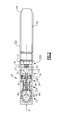
- FIG. 2 schematically illustrates the exhaust liner 16 and the gas turbine engine 20.
- the exhaust liner 16 may be non-linear and/or transition to non-circular to suit airframe requirements. That is, the exhaust liner 16 may be contoured to at least partially extend off the axis A.
- the exhaust liner 16 may be of a linear or non-linear shape within an outer exhaust duct 32D and may include a nozzle section 16N.
- the nozzle section 16N may include various fixed, variable, convergent/divergent, two-dimensional and three-dimensional nozzle systems.
- the gas turbine engine 20 is disclosed herein as a two-spool turbofan that generally incorporates a fan section 22, a compressor section 24, a combustor section 26, a turbine section 28, and an augmenter section 30.
- the sections are defined along the central longitudinal engine axis A.
- augmented low bypass gas turbine engine depicted as an augmented low bypass gas turbine engine in the disclosed non-limiting embodiment, it should be understood that the concepts described herein are applicable to other gas turbine engines including non-augmented engines, geared architecture engines, direct drive turbofans, turboshaft engines, three-spool architecture engines and others.
- the compressor section 24, the combustor section 26 and the turbine section 28 are generally referred to as the engine core.
- the fan section 22 and a low pressure turbine 34 of the turbine section 28 are coupled by a first shaft 36 to define a low spool.
- the compressor section 24 and a high pressure turbine 38 of the turbine section 28 are coupled by a second shaft 40 to define a high spool.
- An outer engine case structure 42 and an inner engine structure 44 define a generally annular secondary flow path 46 around a core flow path 48 of the engine core. It should be understood that various structure within the engine may define the outer engine case structure 42 and the inner engine structure 44 which essentially define an exoskeleton to support the core engine therein. It should be appreciated that the inner engine structure 44 as defined herein may include a turbine exhaust case, a stub liner, an augmenter liner, or any structure generally adjacent to an engine tail cone 50 and within the outer engine case structure 42 to direct the engine core flow.
- Air which enters the fan section 22 is divided between a core flow through the core flow path 48 and a secondary flow through the secondary flow path 46.
- the core flow passes through the combustor section 26, the turbine section 28, then the augmentor section 30 where fuel may be selectively injected and burned to generate additional thrust through the exhaust liner section 32 and the exhaust liner 16.
- the secondary flow may be utilized for a multiple of purposes to include, for example, cooling and pressurization.
- the secondary flow as defined herein is any flow different from the primary combustion gas exhaust core flow.
- the outer engine case structure 42 is mounted to the outer exhaust duct 32D via a removable or retractable exhaust duct segment 32Ds via, for example, V-band clamps 33 due to delta pressures an order of magnitude higher than the inner engine structure 44 and the exhaust liner 16.
- the exhaust duct segment 32Ds may be a split circumferentially in one or more places. That is, the duct segment 32Ds, in one disclosed non-limiting embodiment, includes a cylindrical member defined by a multiple of segments. It should be appreciated that rubber reinforced bellows or other seals may be utilized to permit some relative motion, yet still seal the exhaust duct segment 32Ds between the outer engine case structure 42 and the outer exhaust duct 32D. Once unclamped the bellows may be readily forced away for interior access to the exhaust liner segment 18. That is, the duct segment 32D provides a seal for the secondary flow and generally axially extends along a travel range of the retractable exhaust liner segment 18 ( Figure 3 ).
- the inner engine structure 44 is mounted to the exhaust liner 16 through the retractable exhaust liner segment 18 which may be loosened and then axially telescoped over either the inner engine structure 44 or the exhaust liner 16 along the axis A after removal or retraction of the duct segment 32D ( Figure 3 ).
- the retractable exhaust liner segment 18, in one disclosed non-limiting embodiment, provides clearance for the tail cone 50 for a straight vertical engine installation/removal movement transverse to the axis A ( Figure 4 ).
- the retractable exhaust liner segment 18 may be a split ring that is split circumferentially in one or more places (two segments 18A, 18B shown). That is, the retractable exhaust liner section 18 is essentially a cylindrical member defined by a multiple of segments.
- a flange 52 is located at the interface of each segment 18A, 18B to define one or more fastener apertures 54 ( Figure 6 ). Each flange 52 may be further supported by a gusset 56 to receive a fastener assembly 58 such as a nut and bolt through the apertures 54. It should be appreciated that although two flanges 52 are illustrated for each segment 18A, 18B at a 180 degree displacement, it should be appreciate that only a single flange 52 may be utilized with radial flexing of the retractable exhaust liner segment 18 permitting movement thereof.
- the retractable exhaust liner segment 18 may be manufactured of a nickel alloy base structure and a liner surface 60 coated with a high temperature ceramic material. It should be understood that any type of liner system such as a dual wall, single wall, cooled or uncooled will benefit herefrom.
- the liner surface 60 defines a lap joint 62 adjacent to the interface between the segments 18A', 18B' ( Figure 8 ). The lap joint 62 further insulates the interface.
- the retractable exhaust liner segment 18 includes a locating feature 64.
- the locating feature 64 may be an indentation or other undulation to axially index the retractable exhaust liner segment 18 with respect to the exhaust liner section 32 and the exhaust liner 16.
- the locating feature 64' defines a step surface 66 which provides an inner surface 68 which is generally parallel to the inner surfaces of the exhaust liner section 32 and the exhaust liner 16 ( Figure 10 ).
- each captured fastener assembly 72 includes a T-Bolt 74 which is retained within one segment 18A' by a retainer 76. That is, the T-bolt 74 is pivotally retained within segment 18A'.
- Segment 18A' includes a slot 78 ( Figure 12 ) such that a nut 80 need only be loosened along the T-Bolt 74 then the T-bolt 74 pivoted along a bolt axis B through an open slot 82 in segment 18B" ( Figure 13 ) to assemble/disassemble segment 18B" from segment 18A" without any other separate components. This facilitates the reduction of Foreign Object Damage (FOD).
- FOD Foreign Object Damage
- the retractable exhaust liner segment 18 facilitates tail cone clearance; provides a relatively uncomplicated design; eliminates seals and facilitates a selectively tight interface to provide backpressure and avoid wear from random vibrations.
Landscapes
- Engineering & Computer Science (AREA)
- Mechanical Engineering (AREA)
- General Engineering & Computer Science (AREA)
- Chemical & Material Sciences (AREA)
- Combustion & Propulsion (AREA)
- Supercharger (AREA)
- Exhaust Silencers (AREA)
- Cylinder Crankcases Of Internal Combustion Engines (AREA)
- Turbine Rotor Nozzle Sealing (AREA)
Abstract
Description
- The present disclosure relates to gas turbine engines, and more particularly to an exhaust liner therefor.
- Some environments require a propulsion system in which an engine or exhaust system may be dropped or raised from an airframe for maintenance within the shadow of the airframe.
- A retractable exhaust liner segment according to an exemplary aspect of the present disclosure includes a first retractable exhaust liner segment that defines a first flange. A second retractable exhaust liner segment defines a second flange. A fastener assembly received by the first flange and the second flange to mount the first retractable exhaust liner segment to the second retractable exhaust liner segment.
- A propulsion system according to an exemplary aspect of the present disclosure includes a retractable exhaust liner segment between a gas turbine engine and an exhaust duct.
- A method of maintaining a gas turbine engine according to an exemplary aspect of the present disclosure includes moving a retractable exhaust liner segment along an axis and moving one of a gas turbine engine or an exhaust liner transverse to the axis.
- Various features will become apparent to those skilled in the art from the following detailed description of the disclosed non-limiting embodiment. The drawings that accompany the detailed description can be briefly described as follows:
-
Figure 1 is a general top perspective of an exemplary aircraft with a propulsion system for use with the present disclosure; -
Figure 2 is a general side sectional view of the propulsion system; -
Figure 3 is a general side sectional view of the propulsion system with a retractable exhaust liner segment in a closed position; -
Figure 4 is a general side sectional view of the propulsion system with a retractable exhaust liner segment in an open position; -
Figure 5 is a side view of the retractable exhaust liner segment; -
Figure 6 is a plan view of a flange of the retractable exhaust liner segment; -
Figure 7 is a side view of a flange of the retractable exhaust liner segment showing a fastener assembly according to one non-limiting embodiment; -
Figure 8 is a side view of a flange of the retractable exhaust liner segment according to another non-limiting embodiment; -
Figure 9 is a side view of a locating feature of the retractable exhaust liner segment according to one non-limiting embodiment; -
Figure 10 is a side view of a locating feature of the retractable exhaust liner segment according to another non-limiting embodiment; -
Figure 11 is a side view of a flange of the retractable exhaust liner segment showing a fastener assembly according to another non-limiting embodiment; -
Figure 12 is a plan view of a flange of one segment of the retractable exhaust liner segment ofFigure 11 ; and -
Figure 13 is a plan view of a flange of one segment of the retractable exhaust liner segment ofFigure 11 . -
Figure 1 schematically illustrates anaircraft 10. Some aircraft embed the engines within the vehicle planform to provide an effective balance of aero-performance, packaging, payload integration and survivability. Theaircraft 10 in the disclosed non-limiting embodiment is schematically illustrated as a common air vehicle planform, however, it should be appreciated that any aircraft or vehicle will benefit herefrom and that the planform should not be considered limiting. - The
aircraft 10 generally includes anairframe 12 and apropulsion system 14. Thepropulsion system 14 may be embedded within theairframe 12 and include anexhaust liner 16 and agas turbine engine 20 along a central longitudinal engine axis A. Theexhaust liner 16 andengine 20 are separately mounted within theairframe 12 and each is separately removable within the "shadow" of theairframe 12 via a retractableexhaust liner segment 18. That is, each may be removed and replaced vertically from theairframe 12 with respect to the ground rather than axially along the engine axis A. The retractableexhaust liner segment 18 selectively provides axial installation clearances to avoid damage to engine flanges yet assures a desired backpressure seal when installed. -
Figure 2 schematically illustrates theexhaust liner 16 and thegas turbine engine 20. Theexhaust liner 16 may be non-linear and/or transition to non-circular to suit airframe requirements. That is, theexhaust liner 16 may be contoured to at least partially extend off the axis A. Theexhaust liner 16 may be of a linear or non-linear shape within anouter exhaust duct 32D and may include anozzle section 16N. Thenozzle section 16N may include various fixed, variable, convergent/divergent, two-dimensional and three-dimensional nozzle systems. - The
gas turbine engine 20 is disclosed herein as a two-spool turbofan that generally incorporates afan section 22, acompressor section 24, acombustor section 26, aturbine section 28, and anaugmenter section 30. The sections are defined along the central longitudinal engine axis A. Although depicted as an augmented low bypass gas turbine engine in the disclosed non-limiting embodiment, it should be understood that the concepts described herein are applicable to other gas turbine engines including non-augmented engines, geared architecture engines, direct drive turbofans, turboshaft engines, three-spool architecture engines and others. - The
compressor section 24, thecombustor section 26 and theturbine section 28 are generally referred to as the engine core. Thefan section 22 and alow pressure turbine 34 of theturbine section 28 are coupled by afirst shaft 36 to define a low spool. Thecompressor section 24 and ahigh pressure turbine 38 of theturbine section 28 are coupled by asecond shaft 40 to define a high spool. - An outer
engine case structure 42 and aninner engine structure 44 define a generally annularsecondary flow path 46 around acore flow path 48 of the engine core. It should be understood that various structure within the engine may define the outerengine case structure 42 and theinner engine structure 44 which essentially define an exoskeleton to support the core engine therein. It should be appreciated that theinner engine structure 44 as defined herein may include a turbine exhaust case, a stub liner, an augmenter liner, or any structure generally adjacent to anengine tail cone 50 and within the outerengine case structure 42 to direct the engine core flow. - Air which enters the
fan section 22 is divided between a core flow through thecore flow path 48 and a secondary flow through thesecondary flow path 46. The core flow passes through thecombustor section 26, theturbine section 28, then theaugmentor section 30 where fuel may be selectively injected and burned to generate additional thrust through theexhaust liner section 32 and theexhaust liner 16. The secondary flow may be utilized for a multiple of purposes to include, for example, cooling and pressurization. The secondary flow as defined herein is any flow different from the primary combustion gas exhaust core flow. - The outer
engine case structure 42 is mounted to theouter exhaust duct 32D via a removable or retractable exhaust duct segment 32Ds via, for example, V-band clamps 33 due to delta pressures an order of magnitude higher than theinner engine structure 44 and theexhaust liner 16. The exhaust duct segment 32Ds may be a split circumferentially in one or more places. That is, the duct segment 32Ds, in one disclosed non-limiting embodiment, includes a cylindrical member defined by a multiple of segments. It should be appreciated that rubber reinforced bellows or other seals may be utilized to permit some relative motion, yet still seal the exhaust duct segment 32Ds between the outerengine case structure 42 and theouter exhaust duct 32D. Once unclamped the bellows may be readily forced away for interior access to theexhaust liner segment 18. That is, theduct segment 32D provides a seal for the secondary flow and generally axially extends along a travel range of the retractable exhaust liner segment 18 (Figure 3 ). - The
inner engine structure 44 is mounted to theexhaust liner 16 through the retractableexhaust liner segment 18 which may be loosened and then axially telescoped over either theinner engine structure 44 or theexhaust liner 16 along the axis A after removal or retraction of theduct segment 32D (Figure 3 ). The retractableexhaust liner segment 18, in one disclosed non-limiting embodiment, provides clearance for thetail cone 50 for a straight vertical engine installation/removal movement transverse to the axis A (Figure 4 ). - With reference to
Figure 5 , the retractableexhaust liner segment 18 may be a split ring that is split circumferentially in one or more places (twosegments exhaust liner section 18 is essentially a cylindrical member defined by a multiple of segments. - A
flange 52 is located at the interface of eachsegment Figure 6 ). Eachflange 52 may be further supported by agusset 56 to receive afastener assembly 58 such as a nut and bolt through theapertures 54. It should be appreciated that although twoflanges 52 are illustrated for eachsegment single flange 52 may be utilized with radial flexing of the retractableexhaust liner segment 18 permitting movement thereof. - The retractable
exhaust liner segment 18 may be manufactured of a nickel alloy base structure and aliner surface 60 coated with a high temperature ceramic material. It should be understood that any type of liner system such as a dual wall, single wall, cooled or uncooled will benefit herefrom. In another disclosed, non-limiting embodiment, theliner surface 60 defines a lap joint 62 adjacent to the interface between thesegments 18A', 18B' (Figure 8 ). The lap joint 62 further insulates the interface. - The retractable
exhaust liner segment 18 includes a locatingfeature 64. The locatingfeature 64 may be an indentation or other undulation to axially index the retractableexhaust liner segment 18 with respect to theexhaust liner section 32 and theexhaust liner 16. In another disclosed, non-limiting embodiment, the locating feature 64' defines astep surface 66 which provides aninner surface 68 which is generally parallel to the inner surfaces of theexhaust liner section 32 and the exhaust liner 16 (Figure 10 ). - With reference to
Figure 11 , another disclosed, non-limiting embodiment, includes aflange 70 that supports one or more capturedfastener assemblies 72. Each capturedfastener assembly 72 includes a T-Bolt 74 which is retained within onesegment 18A' by aretainer 76. That is, the T-bolt 74 is pivotally retained withinsegment 18A'.Segment 18A' includes a slot 78 (Figure 12 ) such that anut 80 need only be loosened along the T-Bolt 74 then the T-bolt 74 pivoted along a bolt axis B through anopen slot 82 insegment 18B" (Figure 13 ) to assemble/disassemblesegment 18B" fromsegment 18A" without any other separate components. This facilitates the reduction of Foreign Object Damage (FOD). - With the best mode for carrying out the invention and the operation thereof having been described, certain additional features and benefits of the invention can now be more readily appreciated. For example, the retractable
exhaust liner segment 18 facilitates tail cone clearance; provides a relatively uncomplicated design; eliminates seals and facilitates a selectively tight interface to provide backpressure and avoid wear from random vibrations. - It should be understood that relative positional terms such as "forward," "aft," "upper," "lower," "above," "below," and the like are with reference to the normal operational attitude of the vehicle and should not be considered otherwise limiting.
- It should also be understood that like reference numerals identify corresponding or similar elements throughout the several drawings. It should also be understood that although a particular component arrangement is disclosed in the illustrated embodiment, other arrangements will benefit herefrom.
- Although particular step sequences are shown, described, and claimed, it should be understood that steps may be performed in any order, separated or combined unless otherwise indicated and will still benefit from the present disclosure.
- Although the different non-limiting embodiments have specific illustrated components, the embodiments of this invention are not limited to those particular combinations. It is possible to use some of the components or features from any of the non-limiting embodiments in combination with features or components from any of the other non-limiting embodiments.
- The foregoing description is exemplary rather than defined by the limitations within. Various non-limiting embodiments are disclosed herein, however, one of ordinary skill in the art would recognize that various modifications and variations in light of the above teachings will fall within the scope of the appended claims. It is therefore to be understood that within the scope of the appended claims, the disclosure may be practiced other than as specifically described. For that reason the appended claims should be studied to determine true scope and content.
Claims (15)
- A retractable exhaust liner segment (18) comprising:a first retractable exhaust liner segment (18A) which defines a first flange;a second retractable exhaust liner segment (18B) which defines a second flange; anda fastener assembly (58) received by said first flange and said second flange to mount said first retractable exhaust liner segment (18A) and said second retractable exhaust liner segment (18B).
- The retractable exhaust liner segment (18) as recited in claim 1, wherein said first retractable exhaust liner segment (18A) and said second retractable exhaust liner segment (18B) are each approximately 180 degrees in circumference.
- The retractable exhaust liner segment (18) as recited in claim 1 or 2, wherein said first retractable exhaust liner segment (18A) and said second retractable exhaust liner segment (18B) include a locating feature (64,64').
- The retractable exhaust liner segment (18) as recited in any of claims 1 to 3, wherein said first retractable exhaust liner segment (18A) and said second retractable exhaust liner segment (18B) include a step surface (66).
- A propulsion system (14) comprising:a gas turbine engine (20) along an axis (A);an exhaust liner (16) along the axis (A); anda retractable exhaust liner segment (18) between said gas turbine engine (20) and said exhaust liner (16).
- The system (14) as recited in claim 5, wherein said retractable exhaust liner segment (18) includes a first segment (18A) and a second segment (18B) each approximately 180 degrees in circumference, and optionally wherein said first segment (18A) defines a first flange and said second segment (18B) defines a second flange.
- The system (14) as recited in claim 6, further comprising a fastener assembly (58) received by said first flange and said second flange to mount said first retractable exhaust liner segment (18A) and said second retractable exhaust liner segment (18B).
- The retractable exhaust liner segment (18) or system (14) as recited in any of claims 1 to 4 or 7, wherein said fastener assembly (58) includes a T-bolt (74).
- The retractable exhaust liner segment (18) or system (14) as recited in claim 8, further comprising a retainer (76) to retain said T-bolt (74) within said first flange.
- The retractable exhaust liner segment (18) or system (14) as recited in claim 8 or 9, wherein said second flange includes a slot (82) to receive said T-bolt (74).
- The system (14) as recited in any of claims 5 to 10, wherein said retractable exhaust liner segment (18A) and said exhaust liner (16) are mounted within an outer exhaust duct (32D), said outer exhaust duct (32D) mountable to said gas turbine engine (20) through an exhaust duct segment (32DS).
- The system (14) as recited in any of claims 5 to 11, wherein said retractable exhaust liner segment (18) includes a step surface (66) parallel to an inner surface (68) of said gas turbine engine (20) and said exhaust liner (16).
- A method of maintaining a gas turbine engine (20) comprising:moving a retractable exhaust liner segment (18) along an axis (A); andmoving one of a gas turbine engine (20) or an exhaust liner (16) transverse to the axis (A).
- The method as recited in claim 13, wherein moving the retractable exhaust liner segment (18) further comprises:telescoping the retractable exhaust liner segment (18) along the axis (A) over one of the gas turbine engine (20) or the exhaust liner (16) within an outer exhaust duct (32D); and/orpivoting a T-bolt (74).
- The method as recited in claim 13 or 14, wherein moving one of the gas turbine engine (20) or the exhaust liner (16) transverse to the axis (A) is performed vertically with respect to an airframe (12) and the ground.
Applications Claiming Priority (1)
| Application Number | Priority Date | Filing Date | Title |
|---|---|---|---|
| US13/301,737 US9151183B2 (en) | 2011-11-21 | 2011-11-21 | Retractable exhaust liner segment for gas turbine engines |
Publications (3)
| Publication Number | Publication Date |
|---|---|
| EP2594752A2 true EP2594752A2 (en) | 2013-05-22 |
| EP2594752A3 EP2594752A3 (en) | 2016-12-07 |
| EP2594752B1 EP2594752B1 (en) | 2022-02-16 |
Family
ID=47278153
Family Applications (1)
| Application Number | Title | Priority Date | Filing Date |
|---|---|---|---|
| EP12193408.7A Active EP2594752B1 (en) | 2011-11-21 | 2012-11-20 | Retractable exhaust liner segment for gas turbine engines |
Country Status (2)
| Country | Link |
|---|---|
| US (2) | US9151183B2 (en) |
| EP (1) | EP2594752B1 (en) |
Cited By (1)
| Publication number | Priority date | Publication date | Assignee | Title |
|---|---|---|---|---|
| CN110566364A (en) * | 2019-09-10 | 2019-12-13 | 中国航空工业集团公司西安飞机设计研究所 | Flexible compensation connecting structure of asymmetric spray pipe and engine |
Families Citing this family (3)
| Publication number | Priority date | Publication date | Assignee | Title |
|---|---|---|---|---|
| US9822731B2 (en) * | 2015-03-27 | 2017-11-21 | United Technologies Corporation | Control scheme using variable area turbine and exhaust nozzle to reduce drag |
| EP3088691B1 (en) * | 2015-04-27 | 2019-06-19 | Ansaldo Energia Switzerland AG | Gas turbine disassembly method |
| JP6601621B2 (en) * | 2016-02-05 | 2019-11-06 | コニカミノルタ株式会社 | Image forming apparatus, print control method, and print control program |
Family Cites Families (19)
| Publication number | Priority date | Publication date | Assignee | Title |
|---|---|---|---|---|
| US2580207A (en) * | 1942-05-13 | 1951-12-25 | Power Jets Res & Dev Ltd | Jet pipe for jet-propelled aircraft |
| GB1116542A (en) | 1966-03-15 | 1968-06-06 | Boeing Co | A diffuser arrangement |
| GB1103431A (en) | 1964-09-23 | 1968-02-14 | Bristol Siddeley Engines Ltd | Improvements in aircraft |
| US4000854A (en) | 1975-10-02 | 1977-01-04 | General Electric Company | Thrust vectorable exhaust nozzle |
| US4175385A (en) | 1977-12-12 | 1979-11-27 | General Electric Company | Thrust reverser for an asymmetric aircraft exhaust nozzle |
| US4411134A (en) * | 1981-10-26 | 1983-10-25 | Moir David L | Apparatus for the repair and replacement of transition ducts on jet engines and bracket therefor |
| US4854525A (en) | 1987-05-19 | 1989-08-08 | The Boeing Company | Engine mounting assembly |
| US5064144A (en) | 1987-05-19 | 1991-11-12 | The Boeing Company | Engine mounting assembly |
| US5031836A (en) | 1990-07-10 | 1991-07-16 | United Technologies Corporation | Flexible fairing for airframe/nozzle interface |
| GB2323065B (en) | 1993-03-13 | 1998-12-09 | Rolls Royce Plc | Vectorable nozzle for aircraft |
| US5390877A (en) | 1993-06-25 | 1995-02-21 | Rolls Royce Plc | Vectorable nozzle for aircraft |
| US5577381A (en) | 1994-12-06 | 1996-11-26 | United Technologies Corporation | Exhaust nozzle cooling scheme for gas turbine engine |
| US20060288688A1 (en) * | 2005-06-22 | 2006-12-28 | Jean-Pierre Lair | Turbofan core thrust spoiler |
| US20080010969A1 (en) * | 2006-07-11 | 2008-01-17 | Thomas Anthony Hauer | Gas turbine engine and method of operating same |
| GB0613929D0 (en) | 2006-07-13 | 2006-08-23 | Rolls Royce Plc | An engine core stand arrangement and method of removal and transportation of an engine core |
| GB2449477B (en) * | 2007-05-24 | 2009-05-13 | Rolls Royce Plc | A duct installation |
| EP2479414B1 (en) * | 2007-08-08 | 2015-06-10 | Rohr, Inc. | Variable area fan nozzle with bypass flow |
| US8726675B2 (en) * | 2007-09-07 | 2014-05-20 | The Boeing Company | Scalloped flexure ring |
| FR2929998B1 (en) * | 2008-04-14 | 2011-08-12 | Aircelle Sa | DOUBLE FLOW TURBOREACTOR NACELLE |
-
2011
- 2011-11-21 US US13/301,737 patent/US9151183B2/en active Active
-
2012
- 2012-11-20 EP EP12193408.7A patent/EP2594752B1/en active Active
-
2015
- 2015-07-24 US US14/808,573 patent/US10184358B2/en active Active
Non-Patent Citations (1)
| Title |
|---|
| None |
Cited By (1)
| Publication number | Priority date | Publication date | Assignee | Title |
|---|---|---|---|---|
| CN110566364A (en) * | 2019-09-10 | 2019-12-13 | 中国航空工业集团公司西安飞机设计研究所 | Flexible compensation connecting structure of asymmetric spray pipe and engine |
Also Published As
| Publication number | Publication date |
|---|---|
| US20130125551A1 (en) | 2013-05-23 |
| US9151183B2 (en) | 2015-10-06 |
| EP2594752A3 (en) | 2016-12-07 |
| EP2594752B1 (en) | 2022-02-16 |
| US20160010507A1 (en) | 2016-01-14 |
| US10184358B2 (en) | 2019-01-22 |
Similar Documents
| Publication | Publication Date | Title |
|---|---|---|
| US9951643B2 (en) | Rapid response clearance control system with spring assist for gas turbine engine | |
| US9915162B2 (en) | Flexible feather seal for blade outer air seal gas turbine engine rapid response clearance control system | |
| EP1947298B1 (en) | Slider seal assembly for gas turbine engine | |
| EP2971592B1 (en) | Actuator for gas turbine engine blade outer air seal | |
| US10316683B2 (en) | Gas turbine engine blade outer air seal thermal control system | |
| EP3097274B1 (en) | Accessible rapid response blade tip clearance control system | |
| US10370999B2 (en) | Gas turbine engine rapid response clearance control system with air seal segment interface | |
| EP3055513B1 (en) | Clearance control system for a gas turbine engine and method of controlling a radial tip clearance within a gas turbine engine | |
| US10316684B2 (en) | Rapid response clearance control system for gas turbine engine | |
| US10184358B2 (en) | Retractable exhaust liner segment for gas turbine engines | |
| EP3470632A1 (en) | Seal interface with a deflection control feature | |
| US10557368B2 (en) | Gas turbine engine rapid response clearance control system with variable volume turbine case | |
| EP3023594B1 (en) | Stator assembly with pad interface for a gas turbine engine | |
| US20140290213A1 (en) | Duct blocker seal assembly for a gas turbine engine | |
| US9915228B2 (en) | Air with integral spring for a gas turbine engine exhaust drive | |
| EP3040523B1 (en) | Integrated seal supports | |
| US10378451B2 (en) | Large displacement high temperature seal |
Legal Events
| Date | Code | Title | Description |
|---|---|---|---|
| PUAI | Public reference made under article 153(3) epc to a published international application that has entered the european phase |
Free format text: ORIGINAL CODE: 0009012 |
|
| AK | Designated contracting states |
Kind code of ref document: A2 Designated state(s): AL AT BE BG CH CY CZ DE DK EE ES FI FR GB GR HR HU IE IS IT LI LT LU LV MC MK MT NL NO PL PT RO RS SE SI SK SM TR |
|
| AX | Request for extension of the european patent |
Extension state: BA ME |
|
| RAP1 | Party data changed (applicant data changed or rights of an application transferred) |
Owner name: UNITED TECHNOLOGIES CORPORATION |
|
| PUAL | Search report despatched |
Free format text: ORIGINAL CODE: 0009013 |
|
| AK | Designated contracting states |
Kind code of ref document: A3 Designated state(s): AL AT BE BG CH CY CZ DE DK EE ES FI FR GB GR HR HU IE IS IT LI LT LU LV MC MK MT NL NO PL PT RO RS SE SI SK SM TR |
|
| AX | Request for extension of the european patent |
Extension state: BA ME |
|
| RIC1 | Information provided on ipc code assigned before grant |
Ipc: F01D 25/30 20060101AFI20161102BHEP Ipc: F02K 1/82 20060101ALI20161102BHEP |
|
| STAA | Information on the status of an ep patent application or granted ep patent |
Free format text: STATUS: REQUEST FOR EXAMINATION WAS MADE |
|
| 17P | Request for examination filed |
Effective date: 20170602 |
|
| RBV | Designated contracting states (corrected) |
Designated state(s): AL AT BE BG CH CY CZ DE DK EE ES FI FR GB GR HR HU IE IS IT LI LT LU LV MC MK MT NL NO PL PT RO RS SE SI SK SM TR |
|
| STAA | Information on the status of an ep patent application or granted ep patent |
Free format text: STATUS: EXAMINATION IS IN PROGRESS |
|
| 17Q | First examination report despatched |
Effective date: 20190201 |
|
| RAP1 | Party data changed (applicant data changed or rights of an application transferred) |
Owner name: RAYTHEON TECHNOLOGIES CORPORATION |
|
| GRAP | Despatch of communication of intention to grant a patent |
Free format text: ORIGINAL CODE: EPIDOSNIGR1 |
|
| STAA | Information on the status of an ep patent application or granted ep patent |
Free format text: STATUS: GRANT OF PATENT IS INTENDED |
|
| INTG | Intention to grant announced |
Effective date: 20210917 |
|
| GRAS | Grant fee paid |
Free format text: ORIGINAL CODE: EPIDOSNIGR3 |
|
| GRAA | (expected) grant |
Free format text: ORIGINAL CODE: 0009210 |
|
| STAA | Information on the status of an ep patent application or granted ep patent |
Free format text: STATUS: THE PATENT HAS BEEN GRANTED |
|
| AK | Designated contracting states |
Kind code of ref document: B1 Designated state(s): AL AT BE BG CH CY CZ DE DK EE ES FI FR GB GR HR HU IE IS IT LI LT LU LV MC MK MT NL NO PL PT RO RS SE SI SK SM TR |
|
| REG | Reference to a national code |
Ref country code: GB Ref legal event code: FG4D |
|
| REG | Reference to a national code |
Ref country code: CH Ref legal event code: EP |
|
| REG | Reference to a national code |
Ref country code: DE Ref legal event code: R096 Ref document number: 602012077681 Country of ref document: DE |
|
| REG | Reference to a national code |
Ref country code: AT Ref legal event code: REF Ref document number: 1469006 Country of ref document: AT Kind code of ref document: T Effective date: 20220315 |
|
| REG | Reference to a national code |
Ref country code: IE Ref legal event code: FG4D |
|
| REG | Reference to a national code |
Ref country code: LT Ref legal event code: MG9D |
|
| REG | Reference to a national code |
Ref country code: NL Ref legal event code: MP Effective date: 20220216 |
|
| REG | Reference to a national code |
Ref country code: AT Ref legal event code: MK05 Ref document number: 1469006 Country of ref document: AT Kind code of ref document: T Effective date: 20220216 |
|
| PG25 | Lapsed in a contracting state [announced via postgrant information from national office to epo] |
Ref country code: SE Free format text: LAPSE BECAUSE OF FAILURE TO SUBMIT A TRANSLATION OF THE DESCRIPTION OR TO PAY THE FEE WITHIN THE PRESCRIBED TIME-LIMIT Effective date: 20220216 Ref country code: RS Free format text: LAPSE BECAUSE OF FAILURE TO SUBMIT A TRANSLATION OF THE DESCRIPTION OR TO PAY THE FEE WITHIN THE PRESCRIBED TIME-LIMIT Effective date: 20220216 Ref country code: PT Free format text: LAPSE BECAUSE OF FAILURE TO SUBMIT A TRANSLATION OF THE DESCRIPTION OR TO PAY THE FEE WITHIN THE PRESCRIBED TIME-LIMIT Effective date: 20220616 Ref country code: NO Free format text: LAPSE BECAUSE OF FAILURE TO SUBMIT A TRANSLATION OF THE DESCRIPTION OR TO PAY THE FEE WITHIN THE PRESCRIBED TIME-LIMIT Effective date: 20220516 Ref country code: NL Free format text: LAPSE BECAUSE OF FAILURE TO SUBMIT A TRANSLATION OF THE DESCRIPTION OR TO PAY THE FEE WITHIN THE PRESCRIBED TIME-LIMIT Effective date: 20220216 Ref country code: LT Free format text: LAPSE BECAUSE OF FAILURE TO SUBMIT A TRANSLATION OF THE DESCRIPTION OR TO PAY THE FEE WITHIN THE PRESCRIBED TIME-LIMIT Effective date: 20220216 Ref country code: HR Free format text: LAPSE BECAUSE OF FAILURE TO SUBMIT A TRANSLATION OF THE DESCRIPTION OR TO PAY THE FEE WITHIN THE PRESCRIBED TIME-LIMIT Effective date: 20220216 Ref country code: ES Free format text: LAPSE BECAUSE OF FAILURE TO SUBMIT A TRANSLATION OF THE DESCRIPTION OR TO PAY THE FEE WITHIN THE PRESCRIBED TIME-LIMIT Effective date: 20220216 Ref country code: BG Free format text: LAPSE BECAUSE OF FAILURE TO SUBMIT A TRANSLATION OF THE DESCRIPTION OR TO PAY THE FEE WITHIN THE PRESCRIBED TIME-LIMIT Effective date: 20220516 |
|
| PG25 | Lapsed in a contracting state [announced via postgrant information from national office to epo] |
Ref country code: PL Free format text: LAPSE BECAUSE OF FAILURE TO SUBMIT A TRANSLATION OF THE DESCRIPTION OR TO PAY THE FEE WITHIN THE PRESCRIBED TIME-LIMIT Effective date: 20220216 Ref country code: LV Free format text: LAPSE BECAUSE OF FAILURE TO SUBMIT A TRANSLATION OF THE DESCRIPTION OR TO PAY THE FEE WITHIN THE PRESCRIBED TIME-LIMIT Effective date: 20220216 Ref country code: GR Free format text: LAPSE BECAUSE OF FAILURE TO SUBMIT A TRANSLATION OF THE DESCRIPTION OR TO PAY THE FEE WITHIN THE PRESCRIBED TIME-LIMIT Effective date: 20220517 Ref country code: FI Free format text: LAPSE BECAUSE OF FAILURE TO SUBMIT A TRANSLATION OF THE DESCRIPTION OR TO PAY THE FEE WITHIN THE PRESCRIBED TIME-LIMIT Effective date: 20220216 Ref country code: AT Free format text: LAPSE BECAUSE OF FAILURE TO SUBMIT A TRANSLATION OF THE DESCRIPTION OR TO PAY THE FEE WITHIN THE PRESCRIBED TIME-LIMIT Effective date: 20220216 |
|
| PG25 | Lapsed in a contracting state [announced via postgrant information from national office to epo] |
Ref country code: IS Free format text: LAPSE BECAUSE OF FAILURE TO SUBMIT A TRANSLATION OF THE DESCRIPTION OR TO PAY THE FEE WITHIN THE PRESCRIBED TIME-LIMIT Effective date: 20220616 |
|
| PG25 | Lapsed in a contracting state [announced via postgrant information from national office to epo] |
Ref country code: SM Free format text: LAPSE BECAUSE OF FAILURE TO SUBMIT A TRANSLATION OF THE DESCRIPTION OR TO PAY THE FEE WITHIN THE PRESCRIBED TIME-LIMIT Effective date: 20220216 Ref country code: SK Free format text: LAPSE BECAUSE OF FAILURE TO SUBMIT A TRANSLATION OF THE DESCRIPTION OR TO PAY THE FEE WITHIN THE PRESCRIBED TIME-LIMIT Effective date: 20220216 Ref country code: RO Free format text: LAPSE BECAUSE OF FAILURE TO SUBMIT A TRANSLATION OF THE DESCRIPTION OR TO PAY THE FEE WITHIN THE PRESCRIBED TIME-LIMIT Effective date: 20220216 Ref country code: EE Free format text: LAPSE BECAUSE OF FAILURE TO SUBMIT A TRANSLATION OF THE DESCRIPTION OR TO PAY THE FEE WITHIN THE PRESCRIBED TIME-LIMIT Effective date: 20220216 Ref country code: DK Free format text: LAPSE BECAUSE OF FAILURE TO SUBMIT A TRANSLATION OF THE DESCRIPTION OR TO PAY THE FEE WITHIN THE PRESCRIBED TIME-LIMIT Effective date: 20220216 Ref country code: CZ Free format text: LAPSE BECAUSE OF FAILURE TO SUBMIT A TRANSLATION OF THE DESCRIPTION OR TO PAY THE FEE WITHIN THE PRESCRIBED TIME-LIMIT Effective date: 20220216 |
|
| REG | Reference to a national code |
Ref country code: DE Ref legal event code: R097 Ref document number: 602012077681 Country of ref document: DE |
|
| PG25 | Lapsed in a contracting state [announced via postgrant information from national office to epo] |
Ref country code: AL Free format text: LAPSE BECAUSE OF FAILURE TO SUBMIT A TRANSLATION OF THE DESCRIPTION OR TO PAY THE FEE WITHIN THE PRESCRIBED TIME-LIMIT Effective date: 20220216 |
|
| PLBE | No opposition filed within time limit |
Free format text: ORIGINAL CODE: 0009261 |
|
| STAA | Information on the status of an ep patent application or granted ep patent |
Free format text: STATUS: NO OPPOSITION FILED WITHIN TIME LIMIT |
|
| 26N | No opposition filed |
Effective date: 20221117 |
|
| PG25 | Lapsed in a contracting state [announced via postgrant information from national office to epo] |
Ref country code: SI Free format text: LAPSE BECAUSE OF FAILURE TO SUBMIT A TRANSLATION OF THE DESCRIPTION OR TO PAY THE FEE WITHIN THE PRESCRIBED TIME-LIMIT Effective date: 20220216 |
|
| P01 | Opt-out of the competence of the unified patent court (upc) registered |
Effective date: 20230520 |
|
| PG25 | Lapsed in a contracting state [announced via postgrant information from national office to epo] |
Ref country code: MC Free format text: LAPSE BECAUSE OF FAILURE TO SUBMIT A TRANSLATION OF THE DESCRIPTION OR TO PAY THE FEE WITHIN THE PRESCRIBED TIME-LIMIT Effective date: 20220216 |
|
| REG | Reference to a national code |
Ref country code: CH Ref legal event code: PL |
|
| REG | Reference to a national code |
Ref country code: BE Ref legal event code: MM Effective date: 20221130 |
|
| PG25 | Lapsed in a contracting state [announced via postgrant information from national office to epo] |
Ref country code: LI Free format text: LAPSE BECAUSE OF NON-PAYMENT OF DUE FEES Effective date: 20221130 Ref country code: IT Free format text: LAPSE BECAUSE OF FAILURE TO SUBMIT A TRANSLATION OF THE DESCRIPTION OR TO PAY THE FEE WITHIN THE PRESCRIBED TIME-LIMIT Effective date: 20220216 Ref country code: CH Free format text: LAPSE BECAUSE OF NON-PAYMENT OF DUE FEES Effective date: 20221130 |
|
| PG25 | Lapsed in a contracting state [announced via postgrant information from national office to epo] |
Ref country code: LU Free format text: LAPSE BECAUSE OF NON-PAYMENT OF DUE FEES Effective date: 20221120 |
|
| PG25 | Lapsed in a contracting state [announced via postgrant information from national office to epo] |
Ref country code: IE Free format text: LAPSE BECAUSE OF NON-PAYMENT OF DUE FEES Effective date: 20221120 |
|
| PG25 | Lapsed in a contracting state [announced via postgrant information from national office to epo] |
Ref country code: BE Free format text: LAPSE BECAUSE OF NON-PAYMENT OF DUE FEES Effective date: 20221130 |
|
| PG25 | Lapsed in a contracting state [announced via postgrant information from national office to epo] |
Ref country code: HU Free format text: LAPSE BECAUSE OF FAILURE TO SUBMIT A TRANSLATION OF THE DESCRIPTION OR TO PAY THE FEE WITHIN THE PRESCRIBED TIME-LIMIT; INVALID AB INITIO Effective date: 20121120 |
|
| PG25 | Lapsed in a contracting state [announced via postgrant information from national office to epo] |
Ref country code: CY Free format text: LAPSE BECAUSE OF FAILURE TO SUBMIT A TRANSLATION OF THE DESCRIPTION OR TO PAY THE FEE WITHIN THE PRESCRIBED TIME-LIMIT Effective date: 20220216 |
|
| PG25 | Lapsed in a contracting state [announced via postgrant information from national office to epo] |
Ref country code: MK Free format text: LAPSE BECAUSE OF FAILURE TO SUBMIT A TRANSLATION OF THE DESCRIPTION OR TO PAY THE FEE WITHIN THE PRESCRIBED TIME-LIMIT Effective date: 20220216 |
|
| PG25 | Lapsed in a contracting state [announced via postgrant information from national office to epo] |
Ref country code: TR Free format text: LAPSE BECAUSE OF FAILURE TO SUBMIT A TRANSLATION OF THE DESCRIPTION OR TO PAY THE FEE WITHIN THE PRESCRIBED TIME-LIMIT Effective date: 20220216 |
|
| PG25 | Lapsed in a contracting state [announced via postgrant information from national office to epo] |
Ref country code: MT Free format text: LAPSE BECAUSE OF FAILURE TO SUBMIT A TRANSLATION OF THE DESCRIPTION OR TO PAY THE FEE WITHIN THE PRESCRIBED TIME-LIMIT Effective date: 20220216 |
|
| REG | Reference to a national code |
Ref country code: DE Ref legal event code: R081 Ref document number: 602012077681 Country of ref document: DE Owner name: RTX CORPORATION (N.D.GES.D. STAATES DELAWARE),, US Free format text: FORMER OWNER: RAYTHEON TECHNOLOGIES CORPORATION, FARMINGTON, CT, US |
|
| PGFP | Annual fee paid to national office [announced via postgrant information from national office to epo] |
Ref country code: DE Payment date: 20251022 Year of fee payment: 14 |
|
| PGFP | Annual fee paid to national office [announced via postgrant information from national office to epo] |
Ref country code: GB Payment date: 20251023 Year of fee payment: 14 |
|
| PGFP | Annual fee paid to national office [announced via postgrant information from national office to epo] |
Ref country code: FR Payment date: 20251022 Year of fee payment: 14 |