EP2594699A2 - Modular walling solution - Google Patents
Modular walling solution Download PDFInfo
- Publication number
- EP2594699A2 EP2594699A2 EP12192464.1A EP12192464A EP2594699A2 EP 2594699 A2 EP2594699 A2 EP 2594699A2 EP 12192464 A EP12192464 A EP 12192464A EP 2594699 A2 EP2594699 A2 EP 2594699A2
- Authority
- EP
- European Patent Office
- Prior art keywords
- wall
- panel
- wall panel
- biasing device
- panels
- Prior art date
- Legal status (The legal status is an assumption and is not a legal conclusion. Google has not performed a legal analysis and makes no representation as to the accuracy of the status listed.)
- Granted
Links
Images


Classifications
-
- E—FIXED CONSTRUCTIONS
- E04—BUILDING
- E04B—GENERAL BUILDING CONSTRUCTIONS; WALLS, e.g. PARTITIONS; ROOFS; FLOORS; CEILINGS; INSULATION OR OTHER PROTECTION OF BUILDINGS
- E04B2/00—Walls, e.g. partitions, for buildings; Wall construction with regard to insulation; Connections specially adapted to walls
- E04B2/74—Removable non-load-bearing partitions; Partitions with a free upper edge
- E04B2/7407—Removable non-load-bearing partitions; Partitions with a free upper edge assembled using frames with infill panels or coverings only; made-up of panels and a support structure incorporating posts
- E04B2/7448—Removable non-load-bearing partitions; Partitions with a free upper edge assembled using frames with infill panels or coverings only; made-up of panels and a support structure incorporating posts with separate framed panels without intermediary posts, extending from floor to ceiling
-
- E—FIXED CONSTRUCTIONS
- E04—BUILDING
- E04B—GENERAL BUILDING CONSTRUCTIONS; WALLS, e.g. PARTITIONS; ROOFS; FLOORS; CEILINGS; INSULATION OR OTHER PROTECTION OF BUILDINGS
- E04B2/00—Walls, e.g. partitions, for buildings; Wall construction with regard to insulation; Connections specially adapted to walls
- E04B2/74—Removable non-load-bearing partitions; Partitions with a free upper edge
- E04B2/82—Removable non-load-bearing partitions; Partitions with a free upper edge characterised by the manner in which edges are connected to the building; Means therefor; Special details of easily-removable partitions as far as related to the connection with other parts of the building
- E04B2/821—Connections between two opposed surfaces (i.e. floor and ceiling) by means of a device offering a restraining force acting in the plane of the partition
- E04B2/824—Connections between two opposed surfaces (i.e. floor and ceiling) by means of a device offering a restraining force acting in the plane of the partition restrained elastically at one surface and inelastically at the opposing surface
-
- E—FIXED CONSTRUCTIONS
- E04—BUILDING
- E04B—GENERAL BUILDING CONSTRUCTIONS; WALLS, e.g. PARTITIONS; ROOFS; FLOORS; CEILINGS; INSULATION OR OTHER PROTECTION OF BUILDINGS
- E04B1/00—Constructions in general; Structures which are not restricted either to walls, e.g. partitions, or floors or ceilings or roofs
- E04B1/62—Insulation or other protection; Elements or use of specified material therefor
- E04B1/74—Heat, sound or noise insulation, absorption, or reflection; Other building methods affording favourable thermal or acoustical conditions, e.g. accumulating of heat within walls
- E04B1/76—Heat, sound or noise insulation, absorption, or reflection; Other building methods affording favourable thermal or acoustical conditions, e.g. accumulating of heat within walls specifically with respect to heat only
- E04B1/7675—Insulating linings for the interior face of exterior walls
-
- E—FIXED CONSTRUCTIONS
- E04—BUILDING
- E04B—GENERAL BUILDING CONSTRUCTIONS; WALLS, e.g. PARTITIONS; ROOFS; FLOORS; CEILINGS; INSULATION OR OTHER PROTECTION OF BUILDINGS
- E04B2/00—Walls, e.g. partitions, for buildings; Wall construction with regard to insulation; Connections specially adapted to walls
- E04B2/74—Removable non-load-bearing partitions; Partitions with a free upper edge
- E04B2/7407—Removable non-load-bearing partitions; Partitions with a free upper edge assembled using frames with infill panels or coverings only; made-up of panels and a support structure incorporating posts
- E04B2/7409—Removable non-load-bearing partitions; Partitions with a free upper edge assembled using frames with infill panels or coverings only; made-up of panels and a support structure incorporating posts special measures for sound or thermal insulation, including fire protection
-
- E—FIXED CONSTRUCTIONS
- E04—BUILDING
- E04B—GENERAL BUILDING CONSTRUCTIONS; WALLS, e.g. PARTITIONS; ROOFS; FLOORS; CEILINGS; INSULATION OR OTHER PROTECTION OF BUILDINGS
- E04B2/00—Walls, e.g. partitions, for buildings; Wall construction with regard to insulation; Connections specially adapted to walls
- E04B2/74—Removable non-load-bearing partitions; Partitions with a free upper edge
- E04B2/82—Removable non-load-bearing partitions; Partitions with a free upper edge characterised by the manner in which edges are connected to the building; Means therefor; Special details of easily-removable partitions as far as related to the connection with other parts of the building
- E04B2/828—Connections between partitions and structural walls
-
- E—FIXED CONSTRUCTIONS
- E04—BUILDING
- E04B—GENERAL BUILDING CONSTRUCTIONS; WALLS, e.g. PARTITIONS; ROOFS; FLOORS; CEILINGS; INSULATION OR OTHER PROTECTION OF BUILDINGS
- E04B2/00—Walls, e.g. partitions, for buildings; Wall construction with regard to insulation; Connections specially adapted to walls
- E04B2/74—Removable non-load-bearing partitions; Partitions with a free upper edge
- E04B2002/749—Partitions with screw-type jacks
- E04B2002/7492—Partitions with screw-type jacks used in partitions extending from floor to ceiling
-
- E—FIXED CONSTRUCTIONS
- E04—BUILDING
- E04F—FINISHING WORK ON BUILDINGS, e.g. STAIRS, FLOORS
- E04F13/00—Coverings or linings, e.g. for walls or ceilings
- E04F13/07—Coverings or linings, e.g. for walls or ceilings composed of covering or lining elements; Sub-structures therefor; Fastening means therefor
- E04F13/08—Coverings or linings, e.g. for walls or ceilings composed of covering or lining elements; Sub-structures therefor; Fastening means therefor composed of a plurality of similar covering or lining elements
- E04F13/0801—Separate fastening elements
- E04F13/0803—Separate fastening elements with load-supporting elongated furring elements between wall and covering elements
Definitions
- the present invention relates to a walling solution enhances insulation to a building whilst allowing the building to move.
- This invention relates to an engineered solution where we manufacture off-site a kit formed walling system that provides high levels of thermal, fire and acoustic performance, whilst allowing the building to move.
- the final element required to reduce energy usage is to limit and manage the air flow from inside to outside of the building.
- the cost to heat or cool a room will be dependant on the size of the room's volume and the difference between the outside and the inside temperatures.
- Energy is then expended to lift or lower the room temperature to the required comfort level.
- the longer the air is kept within a room at its comfortable temperature the less energy is required to replace the heat lost (or cooled air) through the building fabric.
- Management of air movement is required to balance the number of changes of air required against the need to limit the loss of 'conditioned' air (hot or cold) out of the building.
- condensation When looking at the management of air into and out of a building an additional important consideration is condensation. This is caused by temperature differentials in the air between the inner and outer leaves of the building. Where warm air hits cold surfaces, condensation is caused, which needs to be resolved to prevent long term erosion of the building.
- any secondary structure system has to conform to all pertaining regulations relating to fire, acoustic and crowd loadings while also offering an ergonomic and quick on site installation.
- the present invention proposes a system of a modular, off-site built, highly insulated, laminated wall panelling solution. This system is then independently fixed and supported away from the inherited structure to prevent thermal bridges. Finally, the individual panels of this inner structure are brought together through a system of dampers which impose a compressive force, effectively sealing the individual panels together, and to the structure of the building.
- the damper system required to achieve an independent, sealed fixing needs to take cognisance of a number of elements; 1) the building imposed load on the panellised walling system, 2) the weight of the panellised walling system and 3) any forces that may act on the system.
- the resultant calculation of these loads enables the manufacture of a calibrated, bi-directional damper system that maintains a constant compressive force on the panellised wall system to the inherited structure. This seals the panel against the structure while still allowing the building to move without deformation of the panel or walling system installed.
- the modular walling system (manufactured to engineering tolerances and not building tolerances) along with the compressive force imposed on the panel, effectively seals the wall to the structure.
- This managed system of controlled air changes means that the number times the air is changed in the building can be reduced. By reducing the number of air changes to the minimum required to suit comfort levels we also reduce the requirement to expend energy to get the new air to the required temperature.
- This invention makes use of a lamination process combining a number of layers of material to achieve the required performance, whilst minimising the thickness of the finished panel.
- the lamination of different materials enables collaboration of different properties to work together.
- the combination of different materials in this invention means we are able to produce a panel that has a significant strength-to-weight ratio. The end result is a panel with reduced thickness and weight, increased strength and very high insulating properties.
- each layer of material has a different resonance level, which in effect confuses sound wave penetration, increasing the acoustic performance.
- the lamination of each layer is 'laterally off-set'. This means that unlike in a traditional wall panel where the edges are all aligned, the edge of each layer of this invention is off-set, creating a 'stepped' edge to the panel. By doing this, sound waves do not have a clear path to travel through the panel at the joints, but have to negotiate each layer separately, and with each layer having different properties, we in effect create a barrier to sound penetration. The same is true for both thermal and fire paths - we create a greater surface area for these to have to travel resulting in significantly increased performance.
- the total system can then tailored to suit the requirement of thermal heat loss, fire resistance, and acoustic reduction required in any given situation. This is achieved by either altering the thickness and type of the materials used in the lamination process, or by increasing the air gaps between the faces of the construction of the panel. In addition, the distance of the panel location away from the inherited structure can be varied to achieve the required optimum performance level.
- the introduction of a heater membrane within the laminates could allow the wall to act as a thermal store. This means that once the wall has been warmed to the correct temperature using the heating membrane, only very small amounts of energy need to be 'sipped' by the membrane to maintain the comfort level required. This is because the density of the wall covering releases the heat into the room slowly and over a large surface area.
- a first aspect of the present invention provides a wall system comprising:
- the at least one biasing device may exert a compressive force on the at least one wall panel.
- the at least one biasing device may allow for both compressive and expansive movement of the at least one wall panel.
- the at least one biasing device may comprise a spring based biasing device.
- the at least one biasing device may comprise at least one damper.
- the at least one biasing device may be calibrated to absorb a pre-defined load on the at least one wall panel.
- the force exerted by the at least one biasing device is adjustable.
- the at least one wall panel may be laminated.
- the at least one wall panel may comprise at least one layer which is thermally insulating, provides acoustic insulation and/or is a fire retardant.
- the at least one wall panel may comprise multiple layers which are laterally offset at an edge of the at least one wall panel.
- the wall system may further comprise attachment means for attaching the upper and/or lower edges of the wall panels to adjacent structures.
- the attachment means may comprise a track.
- the wall system may further comprise a cover strip to cover the biasing device.
- a second aspect of the invention provides a wall structure comprising:
- the structure may comprise a ceiling, soffit, floor or wall.
- the wall structure may comprise a void between the wall and the at least one wall panel.
- the void is sealed, for example with thermal foil.
- the at least one biasing device may be arranged to bias the one or more wall panels against a structure bordering the top of the at least one wall panel, for example a soffit or ceiling.
- the at least one biasing device may be arranged to bias the at least one wall panel against a structure comprising an adjacent wall.
- the wall structure may further comprise loose fill insulation at the base of the at least one wall panel.
- a cover strip may be provided to cover the base of the at least one wall panel whilst allowing the at least one wall panel to move freely behind it.
- the wall is constructed by one or more wall panels.
- This wall structure is suitable for internal walls.
- the wall and wall panels may be separated by a spacer.
- the void between the wall and at least one wall panel may contain a layer of insulation.
- a third aspect of the present invention provides a method of constructing a wall structure comprising the steps of:
- the bordering structure may comprise a ceiling, soffit, floor or wall.
- the at least one wall panel may be positioned to leave a void between the wall and the at least one wall panel.
- the method may comprise the step of sealing the void, for example lining the void with thermal foil or the like.
- the method may comprise the step of sealing the base of the at least one wall panel with loose fill insulation.
- the base of the at least one wall panel may be covered with a cover strip.
- the method may comprise the step of attaching a track to a bordering structure at the top of the at least one wall panel and fitting the at least one wall panel to the track.
- any feature disclosed herein may be replaced by an alternative feature serving the same or a similar purpose.
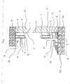
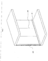
- Figure 1 This shows the configuration of the walling system in relation to an inherited structure 23.
- the laminated panel consists of an inner leaf 14, an insulation layer 15, an outer layer lamination 16 and an optional heater membrane 17. These layers are bonded using adhesives specific to the fire/health issues required for the application. Combined together they form the complete panel 1.
- the complete walling panel 1 (although shown broken in the drawing) runs from the slab 22 to the sofiit 21 and is held in place by the header track 8 which is fixed to the ceiling and base track 2 which is fixed to the slab 22.
- the bottom of the panel has bonded to it a pre-formed profile section 3.
- the panel is put in compression by use of the damper 4 and the adjustment locking nuts 6 washers 7 and the threaded adjustment rod 5 that passes through this profile section 3.
- By winding these components up and compressing the damper it puts an upwards force on the panel sealing it to the header track and creating a void area 9 between the new panel and the inherited structure.
- the damper 4 is calibrated so that when the building moves, the panel 1 at no time loses the compressive force that holds the wall in place.
- the damper 4 is bi-directional meaning that it allows for movement whether that be compressive or expansive. This means that should the floor 22 either drop under live load, or rise back up to its original position if the live load is moved, the damper 4 maintains the panel 1 in place. Therefore the load on damper 4 has been calibrated to absorb imposed load (when the load is greater than the weight of the wall) plus a risk percentage.
- the base is then finished with a closing strip 10 that aesthetically finishes the wall while still allowing the panel 1 to move freely behind it.
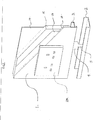
- Figure 2 shows the build up of the construction of the panel where the panel is used as an inner leaf of an external wall.
- 14 shows the inner lamination of the panel with 15 the main insulation 17 the heater membrane and 16 the outer leaf which will end up as the inner face of the wall.
- Figure 2 also shows the 'offset' edge detail between layers 14,15, 16 & 17.
- the panels are manufacture off-site in a factory to a surveyed drawing. During this survey all required service penetrations, such as the plug socket detail 24, will be precut in the production phase. It should also be noted that the depth of the void 9 as shown in figure 1 should be optimised to allow for services to pass behind the face of the panel therefore allowing enough space to fit an electrical back box without the need for chasing of the inherited wall 23.
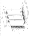
- Figure 3 This shows a typical components set when creating a wall to the inner face of an external wall 23.
- the three panels 1 as shown have been surveyed prior to manufacture to establish the overall height [the distance between 21 and 22] and developed width required to be installed. Any services that need to cut into the panel would be machined into the panel prior to delivery. Windows and door openings likewise will be engineered into the modularised solution and will be part of the kit delivered to the site of installation.
- header track 8 will be fixed directly to the building sofit 21
- bottom track 2 will also be fixed to the slab 22
- likewise track 25 will be fixed to the vertical side of the inherited structure 23.
- the bottom profile section as continuous, but in fact each of the individual panels 1 will have the profile section 3 fitted and bonded to the panel 1 as it leaves the factory.
- the wall panels 1 are then set into the bottom track 2 and slid along until they are in the correct location.
- the head of the panel 1 sits within the track 8.
- the panel is then lined and levelled by means of winding up on the adjustment previously shown in figure 1 , items 6, 5, 7, to put the panel in compression.
- the bi-directional damper 4 will then be under load.
- the adhesive which has been developed to suit the fire, thermal and acoustic requirements, is then applied to the confused joint formed by the off-set of the lamination 14, 15, 16, 17, and the next panel is then positioned in the track 2, pushed along and the joints engaged. The levelling process is then repeated.
- a continuous piece of profile section 3 is positioned between the wall track 25 and the last wall panel 1.
- Attached to this profile section is a series of dampers as per the base section; 4, 5, 6, 7.
- the energy that has been used to condition the air in the room (heating or cooling) is, trapped as there is no direct path for the energy to escape because the thermal bridge has been broken.
- the wall floats and is independent to the inherited structure.
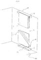
- Figure 4 shows the completed walling installation with the closure strips 10 and a vertical joint strip 26 in place.
- the exposed joint 28 will be awaiting final finish and the total system will be decorated to suit.
- a rebate has been formed at the top of the panel 1 by the removal of a section of the insulation material 15. This allows the panel to be located onto the profile section 3 whilst the front face 16 sits outside that profile section 3 creating a clean finish at the top of the panel and tight abutment to the sofit 21. The Profile section 3 then traps the panel to hold it tightly whilst still allowing it to be slid into place.
- the angle of the profile section 3 allows the inner leaf of the lamination 14 to be easily fed into position
- Figure 5 also shows that prior to installation the inherited structure/wall has the thermal foil 11 applied. This is applied to the total wall surface and includes the return behind the tracks 8 & 2 with any redundant foil removed after installation.
- Figure 6 shows the reverse view of the walling system and the formation of the void 9 which increases the thermal performance of the total system
- the panel 1 can be seen to float with the compressive force of all o the dampers 4 acting on the panel. The adjustment is shown on the exposed length of thread 5.
- the panel 1 is bonded to the profile section 3 by using engineered adhesive 31.
- Figure 7 shows the construction of an internal walling panel used to divide up the usable space within a building. Such walls need equal thermal, acoustic and fire performance properties to marry up with the external walls as described in figures 1 - 6 .
- the panels 1 & 1 are once again off set and held apart by the use of a formed stud 32.
- This stud is disassociated and not connected to the external face of the panel.
- air gaps 35 & 35 we have created a void. This then provides greater resistance to thermal transfer, fire and sound paths.
- the principle of offsetting the laminates has been adopted for this solution but instead of each laminate we have off set the panel creating once again a large surface area and a confused joint between panel sections.
- the studs 32 when used in the walling construction provides flexibility insofar as the manufactured stud can be made to whatever width we require to achieve the required performance of the wall within the building. The greater the width and by association the air gap 35, the higher the wall performance. Therefore with the combination of the laminate thickness, the type of materials used in the lamination, the type of adhesive used and the thickness of the overall wall, the system can be engineered and fine tuned according to the requirements of each application.
- Figure 8 shows more clearly the construction of an internal walling panel and the way that the studs have been rebated back 37 to accept the header track 8.
- the base profile section 3 shows were the adjustment passes through 36 - which then rides up within the void 35 between the two outer panels 1.
- the void or air gap 35 between the two panels is used to allow the services to drop down into the wall and out where required through purpose made service penetration.
- Figure 9 shows how base profile 3 has is made to mirror the confused joint where the panels have been laterally off set. Each off set profile section 3 then inter-connects with the next section 27 to make a continuous run.
- Base plate 39 fits snugly into bottom track 2 and allows the panel to slide into place within the restricted confines of this track. Thus, with the head of the panel trapped by the rebate described in figure 5 , and the bottom of the panel trapped by the base track 2, the panel will be locked into position. Once the panel has been slid into place it is then put into compression through the use of the dampers 4 as described above.
- the profile section 3 includes a double return 38. This provides the structural integrity that supports the panel as we as a large surface area to bond panel 1 to profile section 3.
- Figure 10 shows the component set of the walling system, exclusive of the panel 1.
- the studs 32 will be positioned to suit the structural strength of the panel and any load that may be imposed laterally onto the panel - like that imposed from a crowd load or wind.
- the offset of the profile section 3 shows that the laminations have been staggered and laterally offset to suit the confused joint.
- the studs 32 are designed and positioned to allow for the introduction of an additional insulation layer 34 (not shown here).
- header track 8 and profile section 3 provide the additional benefit that they can be used as a service conduit to run items such as cables or small pipes without having to chase the walls. Additionally the gap at the bottom of the panel can also be used for the same purpose.
- Figure 11 shows the view of the completed wall from above.
- the header track 8 is cut short to allow for the compressive profile section 3 to exert force on the completed set of panels by using the damper detail 4 and it associated assemble 5, 6, 7.
- the closure covering strips 26 & 10 finish the system.
- the confused joints 27 can be seen to be offset.
Landscapes
- Engineering & Computer Science (AREA)
- Architecture (AREA)
- Physics & Mathematics (AREA)
- Electromagnetism (AREA)
- Civil Engineering (AREA)
- Structural Engineering (AREA)
- Acoustics & Sound (AREA)
- Building Environments (AREA)
- Working Measures On Existing Buildindgs (AREA)
Abstract
Description
- The present invention relates to a walling solution enhances insulation to a building whilst allowing the building to move. This invention relates to an engineered solution where we manufacture off-site a kit formed walling system that provides high levels of thermal, fire and acoustic performance, whilst allowing the building to move.
- We all have a need to reduce our energy requirement to heat or cool rooms both at home and at work. To achieve this we need to conserve as much of the energy we've used to heat or cool the building. Therefore we need to insulate our buildings to maintain a constant comfort level.
- To achieve the high levels of insulation required to help conserve energy, we need a medium that provides high levels of thermal resistance. In general terms, this means a substance that traps air. However, the requirement for higher and higher levels of insulation means that the insulation that we apply to our buildings has become thicker and thicker over time and now severely encroaches into the useable space, reducing the floor plates.
- Simply applying insulation to a building will not necessary provide a greater reduction in energy usage. We also need to isolate the inner leaf of the building from the outer leaf. Any path, be it solid or air, that directly connects the two leaves will conduct heat either into or out of the building, by creating what's called a 'Thermal Bridge'. These thermal bridges need to be reduced or removed to increase the energy efficiency of the room. For example, a solid floor that sits directly on the foundations will draw the cold from its connection to the outside. If, however, the floor is suspended from the foundation and insulated from it, the thermal bridge for the cold to travel into the building has been broken and the cold cannot infiltrate the floor, which in turn reduces the need to heat the room.
- The final element required to reduce energy usage is to limit and manage the air flow from inside to outside of the building. The cost to heat or cool a room will be dependant on the size of the room's volume and the difference between the outside and the inside temperatures. Energy is then expended to lift or lower the room temperature to the required comfort level. Ideally the longer the air is kept within a room at its comfortable temperature, the less energy is required to replace the heat lost (or cooled air) through the building fabric. However, this needs to be balanced with the need to refresh the air within the building, preventing the build up of stale air. Management of air movement is required to balance the number of changes of air required against the need to limit the loss of 'conditioned' air (hot or cold) out of the building.
- When looking at the management of air into and out of a building an additional important consideration is condensation. This is caused by temperature differentials in the air between the inner and outer leaves of the building. Where warm air hits cold surfaces, condensation is caused, which needs to be resolved to prevent long term erosion of the building.
- All buildings move, and whatever systems are put into place have to take cognisance of this movement. Movement can either be deflection (caused through a force being directly applied to the building fabric) or a live load deflection (where a body moves within the structure). Therefore, any secondary structure connected to the fabric of the building has to take into account the same movements to prevent deformation of that secondary structure.
- Lastly, any secondary structure system has to conform to all pertaining regulations relating to fire, acoustic and crowd loadings while also offering an ergonomic and quick on site installation.
- To overcome these issues, the present invention proposes a system of a modular, off-site built, highly insulated, laminated wall panelling solution. This system is then independently fixed and supported away from the inherited structure to prevent thermal bridges. Finally, the individual panels of this inner structure are brought together through a system of dampers which impose a compressive force, effectively sealing the individual panels together, and to the structure of the building.
- The damper system required to achieve an independent, sealed fixing needs to take cognisance of a number of elements; 1) the building imposed load on the panellised walling system, 2) the weight of the panellised walling system and 3) any forces that may act on the system. The resultant calculation of these loads enables the manufacture of a calibrated, bi-directional damper system that maintains a constant compressive force on the panellised wall system to the inherited structure. This seals the panel against the structure while still allowing the building to move without deformation of the panel or walling system installed.
- By introducing a new, inner leaf to the building, we have created a new cavity behind this inner structure, which in itself creates a number of advantages. This void area is sealed prior to the introduction of the new inner leaf to increase its thermal performance. The resultant cavity reduces the risk of condensation and, because air is in itself a good insulator, it substantially increases the resistance to thermal transfer.
- The modular walling system (manufactured to engineering tolerances and not building tolerances) along with the compressive force imposed on the panel, effectively seals the wall to the structure. This enables the air changes in the building to be managed. This managed system of controlled air changes means that the number times the air is changed in the building can be reduced. By reducing the number of air changes to the minimum required to suit comfort levels we also reduce the requirement to expend energy to get the new air to the required temperature.
- This invention makes use of a lamination process combining a number of layers of material to achieve the required performance, whilst minimising the thickness of the finished panel. The lamination of different materials enables collaboration of different properties to work together. The combination of different materials in this invention means we are able to produce a panel that has a significant strength-to-weight ratio. The end result is a panel with reduced thickness and weight, increased strength and very high insulating properties.
- In addition, this lamination process and the combination of materials used increases the acoustic performance of the wall. Each different layer of material has a different resonance level, which in effect confuses sound wave penetration, increasing the acoustic performance. To further increase acoustic performance, the lamination of each layer is 'laterally off-set'. This means that unlike in a traditional wall panel where the edges are all aligned, the edge of each layer of this invention is off-set, creating a 'stepped' edge to the panel. By doing this, sound waves do not have a clear path to travel through the panel at the joints, but have to negotiate each layer separately, and with each layer having different properties, we in effect create a barrier to sound penetration. The same is true for both thermal and fire paths - we create a greater surface area for these to have to travel resulting in significantly increased performance.
- By creating this 'stepped' edge to each panel, which is then connected to the adjacent panel with a mirror image edge using a bonding agent (like a common tongue and groove joint), we are also able to achieve a significantly stronger joint due to the increased surface area of that joint. The strength of this joint negates the need for a vertical stud fixing.
- The total system can then tailored to suit the requirement of thermal heat loss, fire resistance, and acoustic reduction required in any given situation. This is achieved by either altering the thickness and type of the materials used in the lamination process, or by increasing the air gaps between the faces of the construction of the panel. In addition, the distance of the panel location away from the inherited structure can be varied to achieve the required optimum performance level.
- Having produced a high performance walling solution, the introduction of a heater membrane within the laminates could allow the wall to act as a thermal store. This means that once the wall has been warmed to the correct temperature using the heating membrane, only very small amounts of energy need to be 'sipped' by the membrane to maintain the comfort level required. This is because the density of the wall covering releases the heat into the room slowly and over a large surface area.
- A first aspect of the present invention provides a wall system comprising:
- at least one wall panel; and
- at least one biasing device which in use exerts a force on the at least one wall panel towards an adjacent structure against which the at least one wall panel abuts in use.
- The at least one biasing device may exert a compressive force on the at least one wall panel. The at least one biasing device may allow for both compressive and expansive movement of the at least one wall panel.
- The at least one biasing device may comprise a spring based biasing device. For example, the at least one biasing device may comprise at least one damper.
- The at least one biasing device may be calibrated to absorb a pre-defined load on the at least one wall panel. The force exerted by the at least one biasing device is adjustable.
- The at least one wall panel may be laminated. The at least one wall panel may comprise at least one layer which is thermally insulating, provides acoustic insulation and/or is a fire retardant. The at least one wall panel may comprise multiple layers which are laterally offset at an edge of the at least one wall panel.
- The wall system may further comprise attachment means for attaching the upper and/or lower edges of the wall panels to adjacent structures. The attachment means may comprise a track.
- The wall system may further comprise a cover strip to cover the biasing device.
- A second aspect of the invention provides a wall structure comprising:
- a wall;
- at least one wall panel arranged in front of the wall and extending the full height and width of the wall;
- at least one biasing device which exerts a force on the at least one wall panels towards a structure bordering the wall.
- The structure may comprise a ceiling, soffit, floor or wall.
- The wall structure may comprise a void between the wall and the at least one wall panel. In one embodiment the void is sealed, for example with thermal foil.
- The at least one biasing device may be arranged to bias the one or more wall panels against a structure bordering the top of the at least one wall panel, for example a soffit or ceiling. The at least one biasing device may be arranged to bias the at least one wall panel against a structure comprising an adjacent wall.
- The wall structure may further comprise loose fill insulation at the base of the at least one wall panel. A cover strip may be provided to cover the base of the at least one wall panel whilst allowing the at least one wall panel to move freely behind it.
- In one embodiment the wall is constructed by one or more wall panels. This wall structure is suitable for internal walls. The wall and wall panels may be separated by a spacer. The void between the wall and at least one wall panel may contain a layer of insulation.
- A third aspect of the present invention provides a method of constructing a wall structure comprising the steps of:
- erecting one or more wall panels in front of a wall;
- using a biasing device to exert a force on the one or
- more wall panels towards a bordering structure.
- The bordering structure may comprise a ceiling, soffit, floor or wall.
- The at least one wall panel may be positioned to leave a void between the wall and the at least one wall panel. The method may comprise the step of sealing the void, for example lining the void with thermal foil or the like.
- The method may comprise the step of sealing the base of the at least one wall panel with loose fill insulation. The base of the at least one wall panel may be covered with a cover strip.
- The method may comprise the step of attaching a track to a bordering structure at the top of the at least one wall panel and fitting the at least one wall panel to the track.
- Preferred features of the second and third aspects of the invention may be as described above in connection with the first aspect.
- Throughout the description and claims of this specification, the words "comprise" and "contain" and variations of the words, for example "comprising" and "comprises", mean "including but not limited to", and do not exclude other additives, components, integers or steps.
- Throughout the description and claims of this specification, the singular encompasses the plural unless the context otherwise requires. In particular, where the indefinite article is used, the specification is to be understood as contemplating plurality as well as singularity, unless the context requires otherwise.
- Other features of the present invention will become apparent from the following example. Generally speaking the invention extends to any novel one, or any novel combination, of the features disclosed in this specification (including any accompanying claims and drawings). Thus features, integers or characteristics described in conjunction with a particular aspect, embodiment or example of the invention are to be understood to be applicable to any other aspect, embodiment or example described herein unless incompatible therewith.
- Moreover unless stated otherwise, any feature disclosed herein may be replaced by an alternative feature serving the same or a similar purpose.
- The invention will now be described solely by way of example and with reference to the accompanying drawings in which:
-
Figure 1 . Shows the cross section of the walling insulation panel fixed between the structure and off set from the building fabric to show the void. In this application the construction is the internal face of an external wall. -
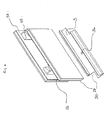
Figure 2 . Shows a cut away section of the walling panel and the build up of the laminations along with the base track, damper and the inclusion of a service box and socket outlet. In this application the construction is the internal face of an external wall. -
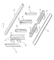
Figure 3 . Shows the complete components set of a walling solution. In this application the construction is the internal face of an external wall. -
Figure 4 . Shows the interface between the sofit and the panel, and the base of the wall and the slab. The panel in this illustration has been broken for clarity. In this application the construction is the internal face of an external wall. -
Figure 5 . Shows a typical completed walling solution. The wall will be awaiting finish. In this application the construction is the internal face of an external wall. -
Figure 6 . Shows the revise side of the wall, illustrating the void/cavity formed when the wall has been installed. It shows the way that the damper works behind and within the walling void. In this application the construction is the internal face of an external wall. -
Figure 7 . Shows the walling panel as shown infigures 1-6 used as an internal dividing wall. It shows the build up of the walling construction. -
Figure 8 . Shows the fabricated panel, the rebate of the stud at the head to accept the header track and the fitment of the panel track in the base of the unit. -
Figure 9 . Shows the configuration of the lower panel track, the typical confused joint off-set and the damper configuration. -
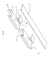
Figure 10 . Shows the configuration of studs and tracks with the actual panel removed for clarity. -
Figure 11 . Shows how the panels set within the tracks prior to the final placement, line and level. -
Figure 1 . This shows the configuration of the walling system in relation to an inheritedstructure 23. - The laminated panel consists of an
inner leaf 14, aninsulation layer 15, anouter layer lamination 16 and anoptional heater membrane 17. These layers are bonded using adhesives specific to the fire/health issues required for the application. Combined together they form the complete panel 1. - The complete walling panel 1 (although shown broken in the drawing) runs from the
slab 22 to thesofiit 21 and is held in place by theheader track 8 which is fixed to the ceiling andbase track 2 which is fixed to theslab 22. - Before the introduction of the new panel, we line the inside of the inherited
structure 23 withthermal foil 11 to effectively seal the new void we create 9. - The bottom of the panel has bonded to it a
pre-formed profile section 3. The panel is put in compression by use of thedamper 4 and theadjustment locking nuts 6washers 7 and the threadedadjustment rod 5 that passes through thisprofile section 3. By winding these components up and compressing the damper, it puts an upwards force on the panel sealing it to the header track and creating a void area 9 between the new panel and the inherited structure. - The
damper 4 is calibrated so that when the building moves, the panel 1 at no time loses the compressive force that holds the wall in place. Thedamper 4 is bi-directional meaning that it allows for movement whether that be compressive or expansive. This means that should thefloor 22 either drop under live load, or rise back up to its original position if the live load is moved, thedamper 4 maintains the panel 1 in place. Therefore the load ondamper 4 has been calibrated to absorb imposed load (when the load is greater than the weight of the wall) plus a risk percentage. - Once the panel is in place and in compression, we need to seal the gaps at the base. The use of
loose fill insulation 20 is then packed between thebottom track 3 and thebase track 2 which seals the gap. Theloose fill insulation 20 allows for the fact that theprofile section 3 may move. - The base is then finished with a
closing strip 10 that aesthetically finishes the wall while still allowing the panel 1 to move freely behind it. - Further options are available where even better insulation is needed through the use of an
insulated floor 12 held in place by acompression joint 13. Likewise, the introduction of a suspended ceiling 18 can be fixed to the panel 1 by means of a fixingblock 19. -
Figure 2 shows the build up of the construction of the panel where the panel is used as an inner leaf of an external wall. 14 shows the inner lamination of the panel with 15 themain insulation 17 the heater membrane and 16 the outer leaf which will end up as the inner face of the wall. -
Figure 2 also shows the 'offset' edge detail betweenlayers - As stated the panels are manufacture off-site in a factory to a surveyed drawing. During this survey all required service penetrations, such as the
plug socket detail 24, will be precut in the production phase. It should also be noted that the depth of the void 9 as shown infigure 1 should be optimised to allow for services to pass behind the face of the panel therefore allowing enough space to fit an electrical back box without the need for chasing of the inheritedwall 23. -
Figure 3 This shows a typical components set when creating a wall to the inner face of anexternal wall 23. The three panels 1 as shown have been surveyed prior to manufacture to establish the overall height [the distance between 21 and 22] and developed width required to be installed. Any services that need to cut into the panel would be machined into the panel prior to delivery. Windows and door openings likewise will be engineered into the modularised solution and will be part of the kit delivered to the site of installation. - The
header track 8 will be fixed directly to thebuilding sofit 21,bottom track 2 will also be fixed to theslab 22, likewise track 25 will be fixed to the vertical side of the inheritedstructure 23. For clarity we have shown 3, the bottom profile section, as continuous, but in fact each of the individual panels 1 will have theprofile section 3 fitted and bonded to the panel 1 as it leaves the factory. - Once all three tracks have been fitted 2, 8, 25, the wall panels 1 are then set into the
bottom track 2 and slid along until they are in the correct location. The head of the panel 1 sits within thetrack 8. When the first panel is in the correct location, the panel is then lined and levelled by means of winding up on the adjustment previously shown infigure 1 ,items bi-directional damper 4 will then be under load. When the installation of the panel 1 is complete, the adhesive, which has been developed to suit the fire, thermal and acoustic requirements, is then applied to the confused joint formed by the off-set of thelamination track 2, pushed along and the joints engaged. The levelling process is then repeated. - Once all of the panels have been installed and bonded a continuous piece of
profile section 3 is positioned between thewall track 25 and the last wall panel 1. Attached to this profile section is a series of dampers as per the base section; 4, 5, 6, 7. As with the base of the panel, adjustment is made to thedampers 4 to put the panel in lateral compression that will both squeezes and closes the joints while making the total walling panel independent to the structure. This allows the building to move without detrimental effect to the walling system. In effect we have formed a 'floating' wall within the inherited structure. - With this system, the energy that has been used to condition the air in the room (heating or cooling) is, trapped as there is no direct path for the energy to escape because the thermal bridge has been broken. The wall floats and is independent to the inherited structure.
-
Figure 4 shows the completed walling installation with the closure strips 10 and a verticaljoint strip 26 in place. The exposed joint 28 will be awaiting final finish and the total system will be decorated to suit. - In
Figure 5 thehead track 8 has been shown as it is fitted to thesofit 21. - A rebate has been formed at the top of the panel 1 by the removal of a section of the
insulation material 15. This allows the panel to be located onto theprofile section 3 whilst thefront face 16 sits outside thatprofile section 3 creating a clean finish at the top of the panel and tight abutment to thesofit 21. TheProfile section 3 then traps the panel to hold it tightly whilst still allowing it to be slid into place. - The angle of the
profile section 3 allows the inner leaf of thelamination 14 to be easily fed into position -
Figure 5 also shows that prior to installation the inherited structure/wall has thethermal foil 11 applied. This is applied to the total wall surface and includes the return behind thetracks 8 & 2 with any redundant foil removed after installation. -
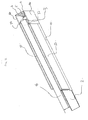
Figure 6 shows the reverse view of the walling system and the formation of the void 9 which increases the thermal performance of the total system The panel 1 can be seen to float with the compressive force of all o thedampers 4 acting on the panel. The adjustment is shown on the exposed length ofthread 5. The panel 1 is bonded to theprofile section 3 by using engineeredadhesive 31. -
Figure 7 shows the construction of an internal walling panel used to divide up the usable space within a building. Such walls need equal thermal, acoustic and fire performance properties to marry up with the external walls as described infigures 1 - 6 . - The construction process and materials used are similar to the panels described in
Figures 1 - 6 however in this case we use two skins separated by anair gap 35. - The panels 1 & 1 are once again off set and held apart by the use of a formed
stud 32. This stud is disassociated and not connected to the external face of the panel. By the introduction ofair gaps 35 & 35 we have created a void. This then provides greater resistance to thermal transfer, fire and sound paths. - The principle of offsetting the laminates has been adopted for this solution but instead of each laminate we have off set the panel creating once again a large surface area and a confused joint between panel sections. The
studs 32 when used in the walling construction provides flexibility insofar as the manufactured stud can be made to whatever width we require to achieve the required performance of the wall within the building. The greater the width and by association theair gap 35, the higher the wall performance. Therefore with the combination of the laminate thickness, the type of materials used in the lamination, the type of adhesive used and the thickness of the overall wall, the system can be engineered and fine tuned according to the requirements of each application. - In
figure 7 an additional layer ofinsulation 34 has been inserted into the void to add to the overall performance of the system. The acoustic performance would also have been increased by the division of the void into 3 separate subsections - twoair gaps 35 and a layer ofinsulation 34. This reduces the risk that acoustic harmonics can be changed by the wave form within the void, eliminating reverberation frequencies. -
Figure 8 shows more clearly the construction of an internal walling panel and the way that the studs have been rebated back 37 to accept theheader track 8. Thebase profile section 3 shows were the adjustment passes through 36 - which then rides up within the void 35 between the two outer panels 1. The void orair gap 35 between the two panels is used to allow the services to drop down into the wall and out where required through purpose made service penetration. -
Figure 9 shows howbase profile 3 has is made to mirror the confused joint where the panels have been laterally off set. Each off setprofile section 3 then inter-connects with thenext section 27 to make a continuous run.Base plate 39 fits snugly intobottom track 2 and allows the panel to slide into place within the restricted confines of this track. Thus, with the head of the panel trapped by the rebate described infigure 5 , and the bottom of the panel trapped by thebase track 2, the panel will be locked into position. Once the panel has been slid into place it is then put into compression through the use of thedampers 4 as described above. - The
profile section 3 includes adouble return 38. This provides the structural integrity that supports the panel as we as a large surface area to bond panel 1 to profilesection 3. -
Figure 10 shows the component set of the walling system, exclusive of the panel 1. - The
studs 32 will be positioned to suit the structural strength of the panel and any load that may be imposed laterally onto the panel - like that imposed from a crowd load or wind. The offset of theprofile section 3 shows that the laminations have been staggered and laterally offset to suit the confused joint. As mentioned above, thestuds 32 are designed and positioned to allow for the introduction of an additional insulation layer 34 (not shown here). - The space created in the
header track 8 andprofile section 3 provide the additional benefit that they can be used as a service conduit to run items such as cables or small pipes without having to chase the walls. Additionally the gap at the bottom of the panel can also be used for the same purpose. -
Figure 11 shows the view of the completed wall from above. Theheader track 8 is cut short to allow for thecompressive profile section 3 to exert force on the completed set of panels by using thedamper detail 4 and it associated assemble 5, 6, 7. Theclosure covering strips 26 & 10 finish the system. Theconfused joints 27 can be seen to be offset.
Claims (15)
- A wall system comprising:at least one wall panel; andat least one biasing device which in use exerts a force on the at least one wall panel towards an adjacent structure against which the at least one wall panel abuts in use.
- A wall system according to any claim 1 wherein the at least one biasing device exerts a compressive force on the at least one wall panel.
- A wall system according to claim 1 wherein the at least one biasing device allows for both compressive and expansive movement of the at least one wall panel.
- A wall system according to any one of the preceding claims wherein the at least one biasing device comprises a spring based biasing device and more preferably the at least one biasing device is adjustable.
- A wall system according to any one of the preceding claims wherein the at least one biasing device is calibrated to absorb a pre-defined load on the at least one wall panel.
- A wall system according to any one of the preceding claims wherein the at least one wall panel is laminated and more preferably the least one wall panel comprises multiple layers which are laterally offset at an edge of the at least one wall panel.
- A wall system according to claim 6 wherein the at least one wall panel comprises at least one layer which is thermally insulating, or which provides acoustic insulation or which is a fire retardant.
- A wall system according to any of the preceding claims further comprising attachment means for attaching the upper and/or lower edges of the wall panels to adjacent structures.
- A wall system according to claim 8 wherein the attachment means comprises a track.
- A wall system according to any one of the preceding claims further comprising a cover strip to cover the biasing device.
- A wall system according to any preceding claim comprising:at least one wall panel; and at least one biasing device which in use exerts a force on the at least one wall panel towards an adjacent structure against which the at least one wall panel abuts, characterised in that the wall system includes a header track and base track for receiving two opposed edges of the at least one wall panel, with there being a bi-directional damper that allows for compressive or expansive movement of the wall panel so that the wall panel is retained in position relative to the header track and base track in order to prevent thermal bridges, the at least one wall panel being positioned in front of a wall to form a void between the at least one wall panel and the wall such that the at least one wall panel is sealed against the adjacent structure while still allowing the adjacent structure and wall panel to move relative to one another.
- A wall structure according to claim 11 wherein the void is sealed, preferably with thermal foil and more preferably the void contains a layer of insulation, preferably loose fill insulation.
- A wall structure according to any preceding claim wherein the structure comprises a ceiling, soffit, floor or wall.
- A wall structure according to any one of claims 11 to 13 wherein the at least one biasing device is arranged to bias the one or more wall panels against a structure bordering the top of the at least one wall panel and/or a structure comprising an adjacent wall.
- A wall structure according to any preceding claim wherein the wall and wall panels are separated by a spacer.
Applications Claiming Priority (1)
| Application Number | Priority Date | Filing Date | Title |
|---|---|---|---|
| GB1119663.1A GB2494721B8 (en) | 2011-11-15 | 2011-11-15 | Modular walling solution |
Publications (3)
| Publication Number | Publication Date |
|---|---|
| EP2594699A2 true EP2594699A2 (en) | 2013-05-22 |
| EP2594699A3 EP2594699A3 (en) | 2014-04-16 |
| EP2594699B1 EP2594699B1 (en) | 2022-04-20 |
Family
ID=45444139
Family Applications (1)
| Application Number | Title | Priority Date | Filing Date |
|---|---|---|---|
| EP12192464.1A Active EP2594699B1 (en) | 2011-11-15 | 2012-11-13 | Modular walling solution |
Country Status (2)
| Country | Link |
|---|---|
| EP (1) | EP2594699B1 (en) |
| GB (1) | GB2494721B8 (en) |
Families Citing this family (14)
| Publication number | Priority date | Publication date | Assignee | Title |
|---|---|---|---|---|
| US10563399B2 (en) | 2007-08-06 | 2020-02-18 | California Expanded Metal Products Company | Two-piece track system |
| CA2790125C (en) * | 2010-02-16 | 2019-04-02 | Gueorgui M. Mihaylov | Device for fluid sampling |
| US10184246B2 (en) | 2010-04-08 | 2019-01-22 | California Expanded Metal Products Company | Fire-rated wall construction product |
| US12215498B2 (en) | 2012-01-20 | 2025-02-04 | Cemco, Llc | Fire-rated joint system |
| US10077550B2 (en) | 2012-01-20 | 2018-09-18 | California Expanded Metal Products Company | Fire-rated joint system |
| US10753084B2 (en) | 2018-03-15 | 2020-08-25 | California Expanded Metal Products Company | Fire-rated joint component and wall assembly |
| US11162259B2 (en) | 2018-04-30 | 2021-11-02 | California Expanded Metal Products Company | Mechanically fastened firestop flute plug |
| US11111666B2 (en) | 2018-08-16 | 2021-09-07 | California Expanded Metal Products Company | Fire or sound blocking components and wall assemblies with fire or sound blocking components |
| US10914065B2 (en) | 2019-01-24 | 2021-02-09 | California Expanded Metal Products Company | Wall joint or sound block component and wall assemblies |
| US11268274B2 (en) | 2019-03-04 | 2022-03-08 | California Expanded Metal Products Company | Two-piece deflection drift angle |
| US11920343B2 (en) * | 2019-12-02 | 2024-03-05 | Cemco, Llc | Fire-rated wall joint component and related assemblies |
| CN111794410A (en) * | 2020-07-10 | 2020-10-20 | 江苏科建新型墙材科技有限公司 | Environment-friendly wall and preparation method thereof |
| US12454824B2 (en) | 2020-08-19 | 2025-10-28 | Cemco, Llc | Building joint with compressible firestopping component |
| US12607009B2 (en) | 2021-12-27 | 2026-04-21 | Cemco, Llc | Fire-rated gaskets and wall assemblies |
Family Cites Families (9)
| Publication number | Priority date | Publication date | Assignee | Title |
|---|---|---|---|---|
| DE2223217C3 (en) * | 1972-05-12 | 1978-04-13 | Otto Ferdinand Cedar Valley Ontario Gasteiger (Kanada) | Movable partition |
| US4454690A (en) * | 1976-09-28 | 1984-06-19 | Panelfold, Inc. | Portable and operable wall system |
| US4103463A (en) * | 1976-09-28 | 1978-08-01 | Panelfold Doors, Inc. | Portable wall system |
| US4277920A (en) * | 1976-09-28 | 1981-07-14 | Panelfold Doors, Inc. | Portable and operable wall systems |
| US4257204A (en) * | 1978-04-26 | 1981-03-24 | Childers Products Company, Inc. | Prefabricated insulated panel and wall structure produced therefrom |
| US4188758A (en) * | 1978-09-20 | 1980-02-19 | Charles Swann | Base for movable wall parts |
| JPH09111926A (en) * | 1995-10-13 | 1997-04-28 | Comany Kk | Partition panel pressure welding device |
| US6112466A (en) * | 1997-02-21 | 2000-09-05 | Hufcor, Inc. | Seal mechanism for partition |
| EP0911455B1 (en) * | 1997-10-20 | 2005-03-23 | Panelock Systems Limited | Furniture |
-
2011
- 2011-11-15 GB GB1119663.1A patent/GB2494721B8/en active Active
-
2012
- 2012-11-13 EP EP12192464.1A patent/EP2594699B1/en active Active
Also Published As
| Publication number | Publication date |
|---|---|
| EP2594699B1 (en) | 2022-04-20 |
| GB2494721A8 (en) | 2023-07-26 |
| GB2494721B8 (en) | 2023-07-26 |
| EP2594699A3 (en) | 2014-04-16 |
| GB2494721B (en) | 2014-02-26 |
| GB201119663D0 (en) | 2011-12-28 |
| GB2494721A (en) | 2013-03-20 |
Similar Documents
| Publication | Publication Date | Title |
|---|---|---|
| EP2594699B1 (en) | Modular walling solution | |
| US10196813B2 (en) | Wall system | |
| JP5580317B2 (en) | Composite panel for walls and method for making the composite panel | |
| US8484916B2 (en) | Panel-sealing and securing system | |
| US7832160B2 (en) | Seismic safe and fire resistant rated edge attached stopless glazing | |
| US8985097B2 (en) | Building-integrated solar thermal micro-channel absorber and method of manufacturing thereof | |
| US9404251B2 (en) | Method for providing a fire safe penetration in building element | |
| KR101590860B1 (en) | Fireproof partition structure and its construction method | |
| US20100251645A1 (en) | Concrete form bucks | |
| US20190249425A1 (en) | Multifunctional ceiling structure | |
| JP7175534B2 (en) | Exterior wall structure of building, heat insulation structure and heat insulation method | |
| US8484907B2 (en) | Methods and apparatus for a building roof structure | |
| WO2020073111A1 (en) | Building system with interior insulation | |
| EP2780514A1 (en) | Insulated wall module | |
| CN101506441B (en) | Exterior wall | |
| WO2014030111A1 (en) | A modular assembly for the construction of insulated building structures | |
| CN203296211U (en) | Break-joint insulation shearing wall | |
| KR102466229B1 (en) | Outer insulation system and method effective for control thermal bridge phenomenon | |
| US20060016143A1 (en) | Insulated tile and stone block wall | |
| US2683980A (en) | Insulated building structure | |
| JP4375809B2 (en) | Exterior wall structure of reinforced concrete exterior heat insulation building and method for constructing exterior wall | |
| UA116106C2 (en) | BUILDING MODULE AND METHOD OF ASSEMBLY OF BUILDING MODULE | |
| JP4282085B2 (en) | Exterior wall structure of reinforced concrete exterior heat insulation building and insulation support panel used | |
| AU2017203899A1 (en) | Laminated Panel System | |
| JP2007285086A (en) | Exterior wall structure of reinforced concrete exterior heat insulation building and insulation support panel used |
Legal Events
| Date | Code | Title | Description |
|---|---|---|---|
| PUAI | Public reference made under article 153(3) epc to a published international application that has entered the european phase |
Free format text: ORIGINAL CODE: 0009012 |
|
| AK | Designated contracting states |
Kind code of ref document: A2 Designated state(s): AL AT BE BG CH CY CZ DE DK EE ES FI FR GB GR HR HU IE IS IT LI LT LU LV MC MK MT NL NO PL PT RO RS SE SI SK SM TR |
|
| AX | Request for extension of the european patent |
Extension state: BA ME |
|
| RIN1 | Information on inventor provided before grant (corrected) |
Inventor name: CONYBEARE, NIGEL PAUL |
|
| PUAL | Search report despatched |
Free format text: ORIGINAL CODE: 0009013 |
|
| AK | Designated contracting states |
Kind code of ref document: A3 Designated state(s): AL AT BE BG CH CY CZ DE DK EE ES FI FR GB GR HR HU IE IS IT LI LT LU LV MC MK MT NL NO PL PT RO RS SE SI SK SM TR |
|
| AX | Request for extension of the european patent |
Extension state: BA ME |
|
| RIC1 | Information provided on ipc code assigned before grant |
Ipc: E04B 1/76 20060101AFI20140311BHEP |
|
| 17P | Request for examination filed |
Effective date: 20141016 |
|
| RBV | Designated contracting states (corrected) |
Designated state(s): AL AT BE BG CH CY CZ DE DK EE ES FI FR GB GR HR HU IE IS IT LI LT LU LV MC MK MT NL NO PL PT RO RS SE SI SK SM TR |
|
| 17Q | First examination report despatched |
Effective date: 20150408 |
|
| STAA | Information on the status of an ep patent application or granted ep patent |
Free format text: STATUS: EXAMINATION IS IN PROGRESS |
|
| GRAP | Despatch of communication of intention to grant a patent |
Free format text: ORIGINAL CODE: EPIDOSNIGR1 |
|
| STAA | Information on the status of an ep patent application or granted ep patent |
Free format text: STATUS: GRANT OF PATENT IS INTENDED |
|
| RIC1 | Information provided on ipc code assigned before grant |
Ipc: E04F 13/08 20060101ALN20210610BHEP Ipc: E04B 2/82 20060101ALN20210610BHEP Ipc: E04B 2/74 20060101ALI20210610BHEP Ipc: E04B 1/76 20060101AFI20210610BHEP |
|
| INTG | Intention to grant announced |
Effective date: 20210622 |
|
| GRAS | Grant fee paid |
Free format text: ORIGINAL CODE: EPIDOSNIGR3 |
|
| GRAA | (expected) grant |
Free format text: ORIGINAL CODE: 0009210 |
|
| STAA | Information on the status of an ep patent application or granted ep patent |
Free format text: STATUS: THE PATENT HAS BEEN GRANTED |
|
| AK | Designated contracting states |
Kind code of ref document: B1 Designated state(s): AL AT BE BG CH CY CZ DE DK EE ES FI FR GB GR HR HU IE IS IT LI LT LU LV MC MK MT NL NO PL PT RO RS SE SI SK SM TR |
|
| RAP3 | Party data changed (applicant data changed or rights of an application transferred) |
Owner name: HERMES SOLUTIONS LTD |
|
| REG | Reference to a national code |
Ref country code: GB Ref legal event code: FG4D |
|
| REG | Reference to a national code |
Ref country code: CH Ref legal event code: EP |
|
| REG | Reference to a national code |
Ref country code: DE Ref legal event code: R096 Ref document number: 602012078063 Country of ref document: DE |
|
| REG | Reference to a national code |
Ref country code: IE Ref legal event code: FG4D |
|
| REG | Reference to a national code |
Ref country code: AT Ref legal event code: REF Ref document number: 1485239 Country of ref document: AT Kind code of ref document: T Effective date: 20220515 |
|
| REG | Reference to a national code |
Ref country code: NL Ref legal event code: FP |
|
| REG | Reference to a national code |
Ref country code: LT Ref legal event code: MG9D |
|
| REG | Reference to a national code |
Ref country code: AT Ref legal event code: MK05 Ref document number: 1485239 Country of ref document: AT Kind code of ref document: T Effective date: 20220420 |
|
| PG25 | Lapsed in a contracting state [announced via postgrant information from national office to epo] |
Ref country code: SE Free format text: LAPSE BECAUSE OF FAILURE TO SUBMIT A TRANSLATION OF THE DESCRIPTION OR TO PAY THE FEE WITHIN THE PRESCRIBED TIME-LIMIT Effective date: 20220420 Ref country code: PT Free format text: LAPSE BECAUSE OF FAILURE TO SUBMIT A TRANSLATION OF THE DESCRIPTION OR TO PAY THE FEE WITHIN THE PRESCRIBED TIME-LIMIT Effective date: 20220822 Ref country code: NO Free format text: LAPSE BECAUSE OF FAILURE TO SUBMIT A TRANSLATION OF THE DESCRIPTION OR TO PAY THE FEE WITHIN THE PRESCRIBED TIME-LIMIT Effective date: 20220720 Ref country code: LT Free format text: LAPSE BECAUSE OF FAILURE TO SUBMIT A TRANSLATION OF THE DESCRIPTION OR TO PAY THE FEE WITHIN THE PRESCRIBED TIME-LIMIT Effective date: 20220420 Ref country code: HR Free format text: LAPSE BECAUSE OF FAILURE TO SUBMIT A TRANSLATION OF THE DESCRIPTION OR TO PAY THE FEE WITHIN THE PRESCRIBED TIME-LIMIT Effective date: 20220420 Ref country code: GR Free format text: LAPSE BECAUSE OF FAILURE TO SUBMIT A TRANSLATION OF THE DESCRIPTION OR TO PAY THE FEE WITHIN THE PRESCRIBED TIME-LIMIT Effective date: 20220721 Ref country code: FI Free format text: LAPSE BECAUSE OF FAILURE TO SUBMIT A TRANSLATION OF THE DESCRIPTION OR TO PAY THE FEE WITHIN THE PRESCRIBED TIME-LIMIT Effective date: 20220420 Ref country code: ES Free format text: LAPSE BECAUSE OF FAILURE TO SUBMIT A TRANSLATION OF THE DESCRIPTION OR TO PAY THE FEE WITHIN THE PRESCRIBED TIME-LIMIT Effective date: 20220420 Ref country code: BG Free format text: LAPSE BECAUSE OF FAILURE TO SUBMIT A TRANSLATION OF THE DESCRIPTION OR TO PAY THE FEE WITHIN THE PRESCRIBED TIME-LIMIT Effective date: 20220720 Ref country code: AT Free format text: LAPSE BECAUSE OF FAILURE TO SUBMIT A TRANSLATION OF THE DESCRIPTION OR TO PAY THE FEE WITHIN THE PRESCRIBED TIME-LIMIT Effective date: 20220420 |
|
| PG25 | Lapsed in a contracting state [announced via postgrant information from national office to epo] |
Ref country code: RS Free format text: LAPSE BECAUSE OF FAILURE TO SUBMIT A TRANSLATION OF THE DESCRIPTION OR TO PAY THE FEE WITHIN THE PRESCRIBED TIME-LIMIT Effective date: 20220420 Ref country code: PL Free format text: LAPSE BECAUSE OF FAILURE TO SUBMIT A TRANSLATION OF THE DESCRIPTION OR TO PAY THE FEE WITHIN THE PRESCRIBED TIME-LIMIT Effective date: 20220420 Ref country code: LV Free format text: LAPSE BECAUSE OF FAILURE TO SUBMIT A TRANSLATION OF THE DESCRIPTION OR TO PAY THE FEE WITHIN THE PRESCRIBED TIME-LIMIT Effective date: 20220420 Ref country code: IS Free format text: LAPSE BECAUSE OF FAILURE TO SUBMIT A TRANSLATION OF THE DESCRIPTION OR TO PAY THE FEE WITHIN THE PRESCRIBED TIME-LIMIT Effective date: 20220820 |
|
| REG | Reference to a national code |
Ref country code: DE Ref legal event code: R097 Ref document number: 602012078063 Country of ref document: DE |
|
| PG25 | Lapsed in a contracting state [announced via postgrant information from national office to epo] |
Ref country code: SM Free format text: LAPSE BECAUSE OF FAILURE TO SUBMIT A TRANSLATION OF THE DESCRIPTION OR TO PAY THE FEE WITHIN THE PRESCRIBED TIME-LIMIT Effective date: 20220420 Ref country code: SK Free format text: LAPSE BECAUSE OF FAILURE TO SUBMIT A TRANSLATION OF THE DESCRIPTION OR TO PAY THE FEE WITHIN THE PRESCRIBED TIME-LIMIT Effective date: 20220420 Ref country code: RO Free format text: LAPSE BECAUSE OF FAILURE TO SUBMIT A TRANSLATION OF THE DESCRIPTION OR TO PAY THE FEE WITHIN THE PRESCRIBED TIME-LIMIT Effective date: 20220420 Ref country code: EE Free format text: LAPSE BECAUSE OF FAILURE TO SUBMIT A TRANSLATION OF THE DESCRIPTION OR TO PAY THE FEE WITHIN THE PRESCRIBED TIME-LIMIT Effective date: 20220420 Ref country code: DK Free format text: LAPSE BECAUSE OF FAILURE TO SUBMIT A TRANSLATION OF THE DESCRIPTION OR TO PAY THE FEE WITHIN THE PRESCRIBED TIME-LIMIT Effective date: 20220420 Ref country code: CZ Free format text: LAPSE BECAUSE OF FAILURE TO SUBMIT A TRANSLATION OF THE DESCRIPTION OR TO PAY THE FEE WITHIN THE PRESCRIBED TIME-LIMIT Effective date: 20220420 |
|
| PLBE | No opposition filed within time limit |
Free format text: ORIGINAL CODE: 0009261 |
|
| STAA | Information on the status of an ep patent application or granted ep patent |
Free format text: STATUS: NO OPPOSITION FILED WITHIN TIME LIMIT |
|
| 26N | No opposition filed |
Effective date: 20230123 |
|
| PG25 | Lapsed in a contracting state [announced via postgrant information from national office to epo] |
Ref country code: AL Free format text: LAPSE BECAUSE OF FAILURE TO SUBMIT A TRANSLATION OF THE DESCRIPTION OR TO PAY THE FEE WITHIN THE PRESCRIBED TIME-LIMIT Effective date: 20220420 |
|
| PG25 | Lapsed in a contracting state [announced via postgrant information from national office to epo] |
Ref country code: SI Free format text: LAPSE BECAUSE OF FAILURE TO SUBMIT A TRANSLATION OF THE DESCRIPTION OR TO PAY THE FEE WITHIN THE PRESCRIBED TIME-LIMIT Effective date: 20220420 |
|
| PG25 | Lapsed in a contracting state [announced via postgrant information from national office to epo] |
Ref country code: MC Free format text: LAPSE BECAUSE OF FAILURE TO SUBMIT A TRANSLATION OF THE DESCRIPTION OR TO PAY THE FEE WITHIN THE PRESCRIBED TIME-LIMIT Effective date: 20220420 |
|
| REG | Reference to a national code |
Ref country code: CH Ref legal event code: PL |
|
| REG | Reference to a national code |
Ref country code: BE Ref legal event code: MM Effective date: 20221130 |
|
| PG25 | Lapsed in a contracting state [announced via postgrant information from national office to epo] |
Ref country code: LI Free format text: LAPSE BECAUSE OF NON-PAYMENT OF DUE FEES Effective date: 20221130 Ref country code: CH Free format text: LAPSE BECAUSE OF NON-PAYMENT OF DUE FEES Effective date: 20221130 |
|
| REG | Reference to a national code |
Ref country code: GB Ref legal event code: 732E Free format text: REGISTERED BETWEEN 20230706 AND 20230712 |
|
| PG25 | Lapsed in a contracting state [announced via postgrant information from national office to epo] |
Ref country code: LU Free format text: LAPSE BECAUSE OF NON-PAYMENT OF DUE FEES Effective date: 20221113 |
|
| PG25 | Lapsed in a contracting state [announced via postgrant information from national office to epo] |
Ref country code: BE Free format text: LAPSE BECAUSE OF NON-PAYMENT OF DUE FEES Effective date: 20221130 |
|
| PG25 | Lapsed in a contracting state [announced via postgrant information from national office to epo] |
Ref country code: IT Free format text: LAPSE BECAUSE OF FAILURE TO SUBMIT A TRANSLATION OF THE DESCRIPTION OR TO PAY THE FEE WITHIN THE PRESCRIBED TIME-LIMIT Effective date: 20220420 |
|
| PG25 | Lapsed in a contracting state [announced via postgrant information from national office to epo] |
Ref country code: HU Free format text: LAPSE BECAUSE OF FAILURE TO SUBMIT A TRANSLATION OF THE DESCRIPTION OR TO PAY THE FEE WITHIN THE PRESCRIBED TIME-LIMIT; INVALID AB INITIO Effective date: 20121113 |
|
| PG25 | Lapsed in a contracting state [announced via postgrant information from national office to epo] |
Ref country code: CY Free format text: LAPSE BECAUSE OF FAILURE TO SUBMIT A TRANSLATION OF THE DESCRIPTION OR TO PAY THE FEE WITHIN THE PRESCRIBED TIME-LIMIT Effective date: 20220420 |
|
| PG25 | Lapsed in a contracting state [announced via postgrant information from national office to epo] |
Ref country code: MK Free format text: LAPSE BECAUSE OF FAILURE TO SUBMIT A TRANSLATION OF THE DESCRIPTION OR TO PAY THE FEE WITHIN THE PRESCRIBED TIME-LIMIT Effective date: 20220420 |
|
| PG25 | Lapsed in a contracting state [announced via postgrant information from national office to epo] |
Ref country code: TR Free format text: LAPSE BECAUSE OF FAILURE TO SUBMIT A TRANSLATION OF THE DESCRIPTION OR TO PAY THE FEE WITHIN THE PRESCRIBED TIME-LIMIT Effective date: 20220420 |
|
| PG25 | Lapsed in a contracting state [announced via postgrant information from national office to epo] |
Ref country code: MT Free format text: LAPSE BECAUSE OF FAILURE TO SUBMIT A TRANSLATION OF THE DESCRIPTION OR TO PAY THE FEE WITHIN THE PRESCRIBED TIME-LIMIT Effective date: 20220420 |
|
| PG25 | Lapsed in a contracting state [announced via postgrant information from national office to epo] |
Ref country code: BG Free format text: LAPSE BECAUSE OF FAILURE TO SUBMIT A TRANSLATION OF THE DESCRIPTION OR TO PAY THE FEE WITHIN THE PRESCRIBED TIME-LIMIT Effective date: 20220420 |
|
| PG25 | Lapsed in a contracting state [announced via postgrant information from national office to epo] |
Ref country code: BG Free format text: LAPSE BECAUSE OF FAILURE TO SUBMIT A TRANSLATION OF THE DESCRIPTION OR TO PAY THE FEE WITHIN THE PRESCRIBED TIME-LIMIT Effective date: 20220420 |
|
| PGFP | Annual fee paid to national office [announced via postgrant information from national office to epo] |
Ref country code: GB Payment date: 20260601 Year of fee payment: 14 |
|
| PGFP | Annual fee paid to national office [announced via postgrant information from national office to epo] |
Ref country code: DE Payment date: 20260601 Year of fee payment: 14 |
|
| PGFP | Annual fee paid to national office [announced via postgrant information from national office to epo] |
Ref country code: IE Payment date: 20260601 Year of fee payment: 14 |
|
| PGFP | Annual fee paid to national office [announced via postgrant information from national office to epo] |
Ref country code: NL Payment date: 20260601 Year of fee payment: 14 |
|
| PGFP | Annual fee paid to national office [announced via postgrant information from national office to epo] |
Ref country code: FR Payment date: 20260601 Year of fee payment: 14 |