EP2594224A1 - Dental platform - Google Patents
Dental platform Download PDFInfo
- Publication number
- EP2594224A1 EP2594224A1 EP11189167.7A EP11189167A EP2594224A1 EP 2594224 A1 EP2594224 A1 EP 2594224A1 EP 11189167 A EP11189167 A EP 11189167A EP 2594224 A1 EP2594224 A1 EP 2594224A1
- Authority
- EP
- European Patent Office
- Prior art keywords
- bone
- mesh
- platform
- dental
- stage
- Prior art date
- Legal status (The legal status is an assumption and is not a legal conclusion. Google has not performed a legal analysis and makes no representation as to the accuracy of the status listed.)
- Withdrawn
Links
Images


Classifications
-
- A—HUMAN NECESSITIES
- A61—MEDICAL OR VETERINARY SCIENCE; HYGIENE
- A61C—DENTISTRY; APPARATUS OR METHODS FOR ORAL OR DENTAL HYGIENE
- A61C8/00—Means to be fixed to the jaw-bone for consolidating natural teeth or for fixing dental prostheses thereon; Dental implants; Implanting tools
- A61C8/0018—Means to be fixed to the jaw-bone for consolidating natural teeth or for fixing dental prostheses thereon; Dental implants; Implanting tools characterised by the shape
- A61C8/0031—Juxtaosseous implants, i.e. implants lying over the outer surface of the jaw bone
-
- A—HUMAN NECESSITIES
- A61—MEDICAL OR VETERINARY SCIENCE; HYGIENE
- A61C—DENTISTRY; APPARATUS OR METHODS FOR ORAL OR DENTAL HYGIENE
- A61C13/00—Dental prostheses; Making same
- A61C13/0003—Making bridge-work, inlays, implants or the like
- A61C13/0006—Production methods
- A61C13/0018—Production methods using laser
-
- A—HUMAN NECESSITIES
- A61—MEDICAL OR VETERINARY SCIENCE; HYGIENE
- A61C—DENTISTRY; APPARATUS OR METHODS FOR ORAL OR DENTAL HYGIENE
- A61C8/00—Means to be fixed to the jaw-bone for consolidating natural teeth or for fixing dental prostheses thereon; Dental implants; Implanting tools
- A61C8/001—Multiple implanting technique, i.e. multiple component implants introduced in the jaw from different directions
-
- A—HUMAN NECESSITIES
- A61—MEDICAL OR VETERINARY SCIENCE; HYGIENE
- A61C—DENTISTRY; APPARATUS OR METHODS FOR ORAL OR DENTAL HYGIENE
- A61C8/00—Means to be fixed to the jaw-bone for consolidating natural teeth or for fixing dental prostheses thereon; Dental implants; Implanting tools
- A61C8/0003—Not used, see subgroups
- A61C8/0004—Consolidating natural teeth
- A61C8/0006—Periodontal tissue or bone regeneration
-
- A—HUMAN NECESSITIES
- A61—MEDICAL OR VETERINARY SCIENCE; HYGIENE
- A61C—DENTISTRY; APPARATUS OR METHODS FOR ORAL OR DENTAL HYGIENE
- A61C8/00—Means to be fixed to the jaw-bone for consolidating natural teeth or for fixing dental prostheses thereon; Dental implants; Implanting tools
- A61C8/0089—Implanting tools or instruments
Definitions
- the present invention relates to the field of dentistry, and more particularly, to a dental platform that replaces a dental implant in areas with a thin bone layer.
- dental implants cannot be used in locations having a thin bone layer. Such locations may be locations in which bone material has been absorbed or eroded to leave but a few millimeters of bone above a nerve channel (e.g. in the mandible), frontal locations with thin bone, and maxillary locations with close sinuses.
- An attempt at a solution is presented e.g. by WIPO Publication No. 2008107356 disclosing specialized disc implants, which however damage the bone significantly, and U.S. Patent No. 5052930 which discloses a lateral connection, likewise however causing much bone damage in the process.
- kits for implantation in a jaw bone comprising: (i) a dental platform comprising an upper portion having a socket for connecting an abutment thereto, and two lateral flaps made of a flexible mesh having a plurality of stabilization spikes and a plurality of openings arranged to receive corresponding anchoring elements, wherein the flexible mesh is produced by laser sintering and is arranged to support and facilitate bone growth, (ii) micro-implants as anchoring elements, each comprising an osteo-integrating external thread for connecting the anchoring element to the jaw bone, a thread-less collar arranged to fit through the opening in the mesh, a socket arranged to allow screwing the anchoring element into the bone, and a curb arranged to affix the mesh to the anchoring element upon the screwing of the micro-implants into the bone; and (iii) a gelatinous material with growth factors arranged to be placed between the bone and the mesh, and fill mesh cavities upon tightening the mesh thereupon.
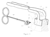
- Figure 1 is a high level schematic illustration of a dental implant platform 110 and components of a dental kit 100 for dental platform 110 , according to some embodiments of the invention.
- Dental platform 110 comprises an upper portion 129 having a socket 115 for connecting an abutment (not shown) thereto, and two lateral flaps 130 made of a flexible mesh 131 having a plurality of stabilization spikes 132 and a plurality of openings 135 arranged to receive corresponding micro-implant anchoring elements 140 .
- Flexible mesh 131 is produced by laser sintering and is arranged to support bone growth.
- Upper portion 129 may further comprise an upper plate 120 with an upper opening 121 arranged to receive a corresponding anchoring element 140 .
- Upper plate 120 may be solid or perforated, and may be produced similarly and continuously to flexible mesh 131 (see Figure 3 ).
- Platform 110 comprises flexible mesh 131 that encloses the implantation location and is connected to the bone by small "micro-implants” as anchoring elements 140 , which may be implanted in different directions. Moreover, due to its flexibility, the form of mesh 131 may be adapted to the bone during implantation. Mesh 131 may hold growth factors that promote bone growth and stabilization of platform 110 (osteointegration). For example, a gelatinous material 150 (patty, see Figure 3 ) with growth factors may be placed between the bone and mesh 131 , and mesh 131 is tightened upon the material, so that it fills its cavities. Mesh 131 may be produced by laser sintering to generate the small mesh cavities and the rough surface that promote osteointegration. Meshes 131 and micro-implants 140 may come in different sizes (widths, lengths) to fit different situations.
- Openings 135 may be arranged in two columns along each lateral flap 130 , and/or in at least two rows along each lateral flap 130 , depending on the intended implantation region, exemplified in Figures 2A-2C .
- Figure 1 illustrates an arrangement with one row and two columns
- Figure 2B illustrates and arrangement with two lines and one column
- Figure 3 illustrates openings 135 arranged in a triangle
- generally various configurations of flaps 131 and opening 135 may be generated to fit to various widths and heights of available bone, in various dental situations.
- Dental implant platforms 110 in different configurations may be supplied within kit 100 to provide the dentist with a full set of solutions for various dental situations.
- Figures 2A-2C are high level schematic illustrations of situations with a thin bone layer and corresponding dental platforms, according to some embodiments of the invention, and illustrate schematically dental situations in which the proposed dental implant platform 110 and implantation method 200 are of special value.
- Figure 2A illustrates a situation of a thin bone layer 90 having a surface that is close to a nerve channel 91 , e.g. 1-2 mm from the mandibular nerve in the mandible. Should a regular implant be placed into the bone as the arrow indicates, the nerve may be severed and normal tactile sensation to the lower lip impaired.
- Figure 2B illustrates a situation of a thin and narrow maxillary bone layer 90 (e.g. 2 mm wide) that does not provide enough support for a regular implant to be placed into the bone as the arrow indicates.
- Figure 2C illustrates a situation of a thin maxillary bone layer 90 over a sinus 92 . This situation does not support regular implants, and requires a preliminary sinus 92 lift surgery prior to implantation.
- Dental implant 110 solves these implantation problems by changing the location of attachment of the bone.
- lateral connection of anchoring elements 140 avoid the risk of damaging the nerve.
- flaps 130 enclose a larger portion of the maxilla and are supported by a large area of the bone.
- several rows of opening 135 may be used to utilize the longitudinal dimension of bone 90 .
- a transverse connector 145 ( Figure 2B ) may be arranged to go through jaw bone 90 from one of openings 135 in one flap 130 to an opposite opening 135 in the second flap 130 , and be secured at the opposite end, for example, connector 145 may have a splitting end that may be split to secure connector 145 upon flap 130 .
- Connector 145 hence may pass through the maxilla and provide a stable connection.
- a wide configuration of flaps, with two or more columns of openings 135 may be employed to ensure good contact to bone 90.
- Figure 3 is a high level schematic illustration of placing a dental platform according to some embodiments of the invention.
- Dental kit 100 may comprise osteo-integrating dental platform 110 as well as several anchoring elements 140 and a gelatinous material 150 with growth factors arranged to be placed between bone 90 and mesh 131 , and fill mesh cavities upon tightening mesh 131 upon bone 90 . Tightening mesh 131 upon bone 90 may be carried out by specialized pliers 160 that may be part of kit 100 .
- Each anchoring element 140 is a micro implant, comprising an external osteo-integrating thread 144 for connecting as anchoring element 140 to jaw bone 90 , a thread-less collar 143 arranged to fit through opening 135 in mesh 131 , a socket 141 arranged to allow screwing anchoring element 140 into bone 90 , and a curb 142 arranged to affix mesh 131 to anchoring elements 140 upon the screwing of anchoring element 140 into bone 90 .
- Micro-implant thread 144 is especially treated to enhance osteo-integration, as in normal implants. Openings 135 and anchoring elements 140 are narrower than 2 mm in diameter.
- Anchoring element 140 as micro implants may be self-tapping, having no need for preliminary drilling as in regular implants. Self-tapping is characterized by a bone condensing effect, enhancing bone strength, instead of the regular bone loss that is associated with the necessary osteotomy due to regular implant placement.
- Socket 115 may be configured in various shapes, according to the planned implantation. Two variants are depicted in Figures 1 and 3 .
- FIG 4 is a schematic illustration of dental kit 100 according to some embodiments of the invention.
- Dental kit 100 may comprise dental platform 110 , gelatinous material 150 with growth factors, pliers 160 for pressing platform 110 upon bone 90 , anchoring elements 140 , a plug 170 and a guiding element 180 for placing anchoring element 140 .
- Pliers 160 may be curved at their end to enhance its maneuverability.
- Pliers 160 may comprise a flattened end 161 arranged to fit upon flaps 130 and press mesh 131 onto bone 90 .
- Flattened end 161 may comprise protrusions 162 fitting into openings 135 to allow temporarily attaching platform 110 to end 161 during its approach to the bone, and further to allow exact and stable placing of platform 110 upon bone 90 .
- Protrusions 162 are structurally configured to release openings 135 , leaving platform 110 in place, upon releasing pliers 160 .
- Primary stability of flaps 130 is enhanced by spikes 132 connected to mesh 131 .
- Micro-implant anchoring element 140 may be placed using a guiding tool 180 arranged to enable exact placing of anchoring elements 140 .
- Guiding tool 180 may comprise a guiding element 183 on its end, that is arranged to hold anchoring element 140 to allow free screwing of anchoring element 140 at least a part of its way through the bone.
- Guiding tool 180 prevents accidental change of axis or orientation of anchoring elements 140 during the operation of screwing them into the bone.
- Guiding element 183 may be as wide as opening 135 and hold anchoring element 140 on curb 142 , collar 143 or thread 144 .
- Guiding element 183 may be openable to allow removing it after placing or fastening of anchoring element 140 .
- Kit 100 may further comprise a plug 170 fitting into socket 115 and arranged to protect socket 115 during bone and gum recovery.
- Plug 170 may be removed after a recovery stage to allow connecting an abutment to socket 115 , kept clean during the recovery by plug 170 .
- Plug 170 may comprise a socket 171 for placing and removing plug 170 from socket 115 .
- Figure 5 is a high level schematic flowchart of an implantation method 200 , according to some embodiments of the invention.
- Method 200 allows connecting an implant to a thin layer of jaw bone, by the following stages: promoting osteointegration (stage 240 ) by producing at least a bone-contacting part of a dental platform by laser sintering (stage 245 ) as a flexible mesh (stage 210 ), and applying bone growth factors into cavities in the mesh (stage 215 ), and attaching the dental platform laterally, beneath the thin layer of bone, to the jaw bone (stage 220 ), using spikes (stage 225 ) and anchoring elements narrower than 2 mm in diameter (stage 230 ).
- Structuring the dental implant platform as a flexible mesh provides the following advantages: increase in the surface area for potential bone growth, support for bone growth factors, the flexibility of the mesh allows fitting the platform to the gum tightly but without application of too large forces on the thin layer of bone, and flexibility in defining the attachment points by deforming the mesh.
- Method 200 further comprises, during the application of the dental implant platform, pressing the mesh against the bone to fit its form to the bone (stage 222 ) and applying gelatinous material with bone growth factors between the mesh and the bone (stage 223 ). Furthermore, method 200 comprises configuring the anchoring elements to push through the bone, without need to remove bone prior to their insertion (stage 235 ), and if necessary, guiding the anchoring elements to their positions (stage 237 ).
- method 200 is a method of constructing an implant, comprising stages 210, 215, 225, 230, 235 and 245 , namely - producing at least a bone-contacting part of the implant by laser sintering (stage 245 ) as a flexible mesh (stage 210 ) with spikes (stage 225 ), applying bone growth factors into cavities in the mesh (stage 215 ), and providing anchoring elements narrower than 2 mm in diameter (stage 230 ) that are configured to push through the bone (stage 235 ) to connect the implant to the bone.
- the disclosed invention has the following decisive advantages.
- the disclosed invention does not require the removal of bone portions and keeps the existing bone substantially intact. This advantage is crucial in cases of little bone mass.
- the disclosed invention applies an opposite principle, that of minimal damage to the bone.
- the disclosed invention ensures a much closer contact of the implant to the bone, due to the flexible mesh, and does not require inflicting bone damage - neither during the fitting of the implant to the form of the existing bone, nor during the connection of the implant to the bone.
- the hereby suggested system helps in building additional bone mass. While common implants require bone removal (drilling) prior to implantation, the micro implant anchoring elements only push through the bone, compacting it in the process, and do not require prior drilling. This feature, together with the application of bone growth factors in combination with the flexible mesh structure, provide maximal bone growth, exactly in the dental situations in which such growth is mostly desired.
Landscapes
- Health & Medical Sciences (AREA)
- Animal Behavior & Ethology (AREA)
- Life Sciences & Earth Sciences (AREA)
- Veterinary Medicine (AREA)
- Public Health (AREA)
- Oral & Maxillofacial Surgery (AREA)
- Dentistry (AREA)
- Epidemiology (AREA)
- General Health & Medical Sciences (AREA)
- Orthopedic Medicine & Surgery (AREA)
- Physics & Mathematics (AREA)
- Engineering & Computer Science (AREA)
- Optics & Photonics (AREA)
- Manufacturing & Machinery (AREA)
- Dental Prosthetics (AREA)
Abstract
Description
- The present invention relates to the field of dentistry, and more particularly, to a dental platform that replaces a dental implant in areas with a thin bone layer.
- Due to their size, dental implants cannot be used in locations having a thin bone layer. Such locations may be locations in which bone material has been absorbed or eroded to leave but a few millimeters of bone above a nerve channel (e.g. in the mandible), frontal locations with thin bone, and maxillary locations with close sinuses. An attempt at a solution is presented e.g. by WIPO Publication No.
2008107356 disclosing specialized disc implants, which however damage the bone significantly, andU.S. Patent No. 5052930 which discloses a lateral connection, likewise however causing much bone damage in the process. - One aspect of the present invention provides a kit for implantation in a jaw bone comprising: (i) a dental platform comprising an upper portion having a socket for connecting an abutment thereto, and two lateral flaps made of a flexible mesh having a plurality of stabilization spikes and a plurality of openings arranged to receive corresponding anchoring elements, wherein the flexible mesh is produced by laser sintering and is arranged to support and facilitate bone growth, (ii) micro-implants as anchoring elements, each comprising an osteo-integrating external thread for connecting the anchoring element to the jaw bone, a thread-less collar arranged to fit through the opening in the mesh, a socket arranged to allow screwing the anchoring element into the bone, and a curb arranged to affix the mesh to the anchoring element upon the screwing of the micro-implants into the bone; and (iii) a gelatinous material with growth factors arranged to be placed between the bone and the mesh, and fill mesh cavities upon tightening the mesh thereupon.
- For a better understanding of embodiments of the invention and to show how the same may be carried into effect, reference will now be made, purely by way of example, to the accompanying drawings in which like numerals designate corresponding elements or sections throughout.
- In the accompanying drawings:
-
Figure 1 is a high level schematic illustration of a dental platform according to some embodiments of the invention, -
Figures 2A-2C are high level schematic illustrations of situations with a thin bone layer and corresponding dental platforms, according to some embodiments of the invention, -
Figure 3 is a high level schematic illustration of placing a dental platform according to some embodiments of the invention, -
Figure 4 is a schematic illustration of the dental kit according to some embodiments of the invention, and -
Figure 5 is a high level schematic flowchart of an implantation method, according to some embodiments of the invention. - The drawings together with the following detailed description make apparent to those skilled in the art how the invention may be embodied in practice.
- With specific reference now to the drawings in detail, it is stressed that the particulars shown are by way of example and for purposes of illustrative discussion of the preferred embodiments of the present invention only, and are presented in the cause of providing what is believed to be the most useful and readily understood description of the principles and conceptual aspects of the invention. In this regard, no attempt is made to show structural details of the invention in more detail than is necessary for a fundamental understanding of the invention, the description taken with the drawings making apparent to those skilled in the art how the several forms of the invention may be embodied in practice.
- Before explaining at least one embodiment of the invention in detail, it is to be understood that the invention is not limited in its application to the details of construction and the arrangement of the components set forth in the following description or illustrated in the drawings. The invention is applicable to other embodiments or of being practiced or carried out in various ways. Also, it is to be understood that the phraseology and terminology employed herein is for the purpose of description and should not be regarded as limiting.
-
Figure 1 is a high level schematic illustration of adental implant platform 110 and components of adental kit 100 fordental platform 110, according to some embodiments of the invention. -
Dental platform 110 comprises anupper portion 129 having asocket 115 for connecting an abutment (not shown) thereto, and twolateral flaps 130 made of aflexible mesh 131 having a plurality ofstabilization spikes 132 and a plurality ofopenings 135 arranged to receive correspondingmicro-implant anchoring elements 140.Flexible mesh 131 is produced by laser sintering and is arranged to support bone growth. -
Upper portion 129 may further comprise anupper plate 120 with anupper opening 121 arranged to receive acorresponding anchoring element 140.Upper plate 120 may be solid or perforated, and may be produced similarly and continuously to flexible mesh 131 (seeFigure 3 ). -
Platform 110 comprisesflexible mesh 131 that encloses the implantation location and is connected to the bone by small "micro-implants" asanchoring elements 140, which may be implanted in different directions. Moreover, due to its flexibility, the form ofmesh 131 may be adapted to the bone during implantation.Mesh 131 may hold growth factors that promote bone growth and stabilization of platform 110 (osteointegration). For example, a gelatinous material 150 (patty, seeFigure 3 ) with growth factors may be placed between the bone andmesh 131, andmesh 131 is tightened upon the material, so that it fills its cavities.Mesh 131 may be produced by laser sintering to generate the small mesh cavities and the rough surface that promote osteointegration.Meshes 131 and micro-implants 140 may come in different sizes (widths, lengths) to fit different situations. -
Openings 135 may be arranged in two columns along eachlateral flap 130, and/or in at least two rows along eachlateral flap 130, depending on the intended implantation region, exemplified inFigures 2A-2C . For example,Figure 1 illustrates an arrangement with one row and two columns,Figure 2B illustrates and arrangement with two lines and one column,Figure 3 illustratesopenings 135 arranged in a triangle, and generally various configurations offlaps 131 andopening 135 may be generated to fit to various widths and heights of available bone, in various dental situations.Dental implant platforms 110 in different configurations may be supplied withinkit 100 to provide the dentist with a full set of solutions for various dental situations. -
Figures 2A-2C are high level schematic illustrations of situations with a thin bone layer and corresponding dental platforms, according to some embodiments of the invention, and illustrate schematically dental situations in which the proposeddental implant platform 110 andimplantation method 200 are of special value.Figure 2A illustrates a situation of athin bone layer 90 having a surface that is close to anerve channel 91, e.g. 1-2 mm from the mandibular nerve in the mandible. Should a regular implant be placed into the bone as the arrow indicates, the nerve may be severed and normal tactile sensation to the lower lip impaired. -
Figure 2B illustrates a situation of a thin and narrow maxillary bone layer 90 (e.g. 2 mm wide) that does not provide enough support for a regular implant to be placed into the bone as the arrow indicates.Figure 2C illustrates a situation of a thinmaxillary bone layer 90 over asinus 92. This situation does not support regular implants, and requires apreliminary sinus 92 lift surgery prior to implantation. -
Dental implant 110 solves these implantation problems by changing the location of attachment of the bone. In the situation ofFigure 2A , lateral connection ofanchoring elements 140 avoid the risk of damaging the nerve. In the situation ofFigure 2B ,flaps 130 enclose a larger portion of the maxilla and are supported by a large area of the bone. In this case, several rows of opening 135 may be used to utilize the longitudinal dimension ofbone 90. In some of these cases, a transverse connector 145 (Figure 2B ) may be arranged to go throughjaw bone 90 from one ofopenings 135 in oneflap 130 to anopposite opening 135 in thesecond flap 130, and be secured at the opposite end, for example,connector 145 may have a splitting end that may be split to secureconnector 145 uponflap 130. The end may then be flattened (e.g. surplus material may be cut or otherwise removed) to minimize disturbance to the patient.Connector 145 hence may pass through the maxilla and provide a stable connection. In the situation ofFigure 2C , a wide configuration of flaps, with two or more columns ofopenings 135 may be employed to ensure good contact tobone 90. -
Figure 3 is a high level schematic illustration of placing a dental platform according to some embodiments of the invention. -
Dental kit 100 may comprise osteo-integratingdental platform 110 as well asseveral anchoring elements 140 and agelatinous material 150 with growth factors arranged to be placed betweenbone 90 andmesh 131, and fill mesh cavities upon tighteningmesh 131 uponbone 90.Tightening mesh 131 uponbone 90 may be carried out byspecialized pliers 160 that may be part ofkit 100. - Each
anchoring element 140 is a micro implant, comprising an external osteo-integratingthread 144 for connecting asanchoring element 140 tojaw bone 90, athread-less collar 143 arranged to fit throughopening 135 inmesh 131, asocket 141 arranged to allowscrewing anchoring element 140 intobone 90, and acurb 142 arranged to affixmesh 131 to anchoringelements 140 upon the screwing of anchoringelement 140 intobone 90.Micro-implant thread 144 is especially treated to enhance osteo-integration, as in normal implants.Openings 135 andanchoring elements 140 are narrower than 2 mm in diameter. Anchoringelement 140 as micro implants may be self-tapping, having no need for preliminary drilling as in regular implants. Self-tapping is characterized by a bone condensing effect, enhancing bone strength, instead of the regular bone loss that is associated with the necessary osteotomy due to regular implant placement. -
Socket 115 may be configured in various shapes, according to the planned implantation. Two variants are depicted inFigures 1 and3 . -
Figure 4 is a schematic illustration ofdental kit 100 according to some embodiments of the invention.Dental kit 100 may comprisedental platform 110,gelatinous material 150 with growth factors,pliers 160 forpressing platform 110 uponbone 90,anchoring elements 140, aplug 170 and a guidingelement 180 for placinganchoring element 140. -
Pliers 160 may be curved at their end to enhance its maneuverability.Pliers 160 may comprise a flattenedend 161 arranged to fit uponflaps 130 andpress mesh 131 ontobone 90. Flattenedend 161 may compriseprotrusions 162 fitting intoopenings 135 to allow temporarily attachingplatform 110 to end 161 during its approach to the bone, and further to allow exact and stable placing ofplatform 110 uponbone 90.Protrusions 162 are structurally configured to releaseopenings 135, leavingplatform 110 in place, upon releasingpliers 160. Primary stability offlaps 130 is enhanced byspikes 132 connected to mesh 131. -
Micro-implant anchoring element 140 may be placed using aguiding tool 180 arranged to enable exact placing of anchoringelements 140. Guidingtool 180 may comprise a guidingelement 183 on its end, that is arranged to hold anchoringelement 140 to allow free screwing of anchoringelement 140 at least a part of its way through the bone. Guidingtool 180 prevents accidental change of axis or orientation of anchoringelements 140 during the operation of screwing them into the bone. Guidingelement 183 may be as wide as opening 135 and hold anchoringelement 140 oncurb 142,collar 143 orthread 144. Guidingelement 183 may be openable to allow removing it after placing or fastening of anchoringelement 140. -
Kit 100 may further comprise aplug 170 fitting intosocket 115 and arranged to protectsocket 115 during bone and gum recovery. Plug 170 may be removed after a recovery stage to allow connecting an abutment tosocket 115, kept clean during the recovery byplug 170. Plug 170 may comprise asocket 171 for placing and removingplug 170 fromsocket 115. -
Figure 5 is a high level schematic flowchart of animplantation method 200, according to some embodiments of the invention. -
Method 200 allows connecting an implant to a thin layer of jaw bone, by the following stages: promoting osteointegration (stage 240) by producing at least a bone-contacting part of a dental platform by laser sintering (stage 245) as a flexible mesh (stage 210), and applying bone growth factors into cavities in the mesh (stage 215), and attaching the dental platform laterally, beneath the thin layer of bone, to the jaw bone (stage 220), using spikes (stage 225) and anchoring elements narrower than 2 mm in diameter (stage 230). Structuring the dental implant platform as a flexible mesh (stage 210) provides the following advantages: increase in the surface area for potential bone growth, support for bone growth factors, the flexibility of the mesh allows fitting the platform to the gum tightly but without application of too large forces on the thin layer of bone, and flexibility in defining the attachment points by deforming the mesh. -
Method 200 further comprises, during the application of the dental implant platform, pressing the mesh against the bone to fit its form to the bone (stage 222) and applying gelatinous material with bone growth factors between the mesh and the bone (stage 223). Furthermore,method 200 comprises configuring the anchoring elements to push through the bone, without need to remove bone prior to their insertion (stage 235), and if necessary, guiding the anchoring elements to their positions (stage 237). - According to aspects of the current invention,
method 200 is a method of constructing an implant, comprisingstages - In comparison to prior art documents, the disclosed invention has the following decisive advantages. In contrast to laterally inserted disc implants, which likewise provide a surface contact between the implant and the bone, the disclosed invention does not require the removal of bone portions and keeps the existing bone substantially intact. This advantage is crucial in cases of little bone mass. The disclosed invention applies an opposite principle, that of minimal damage to the bone. In contrast to other documents, such as
US5052930 , which provide surface contact between the bone and the implant, the disclosed invention ensures a much closer contact of the implant to the bone, due to the flexible mesh, and does not require inflicting bone damage - neither during the fitting of the implant to the form of the existing bone, nor during the connection of the implant to the bone. - In contrast to any known implant, the hereby suggested system helps in building additional bone mass. While common implants require bone removal (drilling) prior to implantation, the micro implant anchoring elements only push through the bone, compacting it in the process, and do not require prior drilling. This feature, together with the application of bone growth factors in combination with the flexible mesh structure, provide maximal bone growth, exactly in the dental situations in which such growth is mostly desired.
- In the above description, an embodiment is an example or implementation of the invention. The various appearances of "one embodiment", "an embodiment" or "some embodiments" do not necessarily all refer to the same embodiments.
- Although various features of the invention may be described in the context of a single embodiment, the features may also be provided separately or in any suitable combination. Conversely, although the invention may be described herein in the context of separate embodiments for clarity, the invention may also be implemented in a single embodiment.
- Furthermore, it is to be understood that the invention can be carried out or practiced in various ways and that the invention can be implemented in embodiments other than the ones outlined in the description above.
- The invention is not limited to those diagrams or to the corresponding descriptions. For example, flow need not move through each illustrated box or state, or in exactly the same order as illustrated and described.
- Meanings of technical and scientific terms used herein are to be commonly understood as by one of ordinary skill in the art to which the invention belongs, unless otherwise defined.
- While the invention has been described with respect to a limited number of embodiments, these should not be construed as limitations on the scope of the invention, but rather as exemplifications of some of the preferred embodiments. Other possible variations, modifications, and applications are also within the scope of the invention.
Claims (12)
- A dental platform (110) comprising:an upper portion (129) having a socket (115) for connecting an abutment thereto,
andtwo lateral flaps (130) made of a flexible mesh (131) having a plurality of stabilization spikes (132) and a plurality of openings (135) arranged to receive corresponding anchoring elements (140),wherein the flexible mesh (131) is produced by laser sintering and is arranged to support and facilitate bone growth. - The dental platform (110) of claim 1, wherein the upper portion (129) further comprises an upper opening (121) arranged to receive a corresponding anchoring element (140).
- The dental platform (110) of claim 1, wherein the openings (135) are arranged in two columns along each lateral flap (130).
- The dental platform (110) of claim 1, wherein the openings (135) are arranged in at least two rows along each lateral flap (130).
- The dental platform (110) of claim 1, wherein the openings (130) are narrower than 2 mm in diameter.
- A dental kit (100) comprising:the dental platform (110) of claim 1,a plurality of anchoring elements (140), each comprising:wherein the anchoring elements (140) are configured to push through the jaw bone (90), without need to remove bone prior to their insertion; andan external thread (144) for connecting the anchoring element (140) to a jaw bone (90),a thread-less collar (143) arranged to fit through the opening (135) in the mesh (131),a socket (141) arranged to allow screwing the anchoring element (140) into the bone (90), anda curb (142) arranged to affix the mesh (131) to the anchoring element (140) upon the screwing of the anchoring element (140) into the bone (90),
a gelatinous material (150) holding growth factors and arranged to be placed between the bone (90) and the mesh (131), and fill mesh cavities upon tightening the mesh (131) thereupon. - The kit (100) of claim 6, further comprising pliers (160) arranged to tighten the mesh (131) upon the jaw bone (90).
- The kit (100) of claim 6, further comprising a connector (145) arranged to go through the jaw bone (90) from one of the openings (135) in the mesh (131) to an opposite opening (135) in the mesh (131), and be secured at the opposite end.
- The kit (100) of claim 6, further comprising a plug (170) fitting into the socket (115) and arranged to protect the socket (115) during bone and gum recovery.
- The kit (100) of claim 6, further comprising a guiding element (180) arranged to enable exact placing of the anchoring elements (140).
- The kit (100) of claim 6, wherein the openings (135) and the anchoring elements (140) are narrower than 2 mm in diameter.
- A method of constructing an implant, comprising:producing at least a bone-contacting part of the implant by laser sintering (stage 245) as a flexible mesh (stage 210) with spikes (stage 225),applying bone growth factors into cavities in the mesh (stage 215) providing anchoring elements narrower than 2 mm in diameter (stage 230) that are configured to push through the bone (stage 235) to connect the implant to the bone.
Priority Applications (1)
| Application Number | Priority Date | Filing Date | Title |
|---|---|---|---|
| EP11189167.7A EP2594224A1 (en) | 2011-11-15 | 2011-11-15 | Dental platform |
Applications Claiming Priority (1)
| Application Number | Priority Date | Filing Date | Title |
|---|---|---|---|
| EP11189167.7A EP2594224A1 (en) | 2011-11-15 | 2011-11-15 | Dental platform |
Publications (1)
| Publication Number | Publication Date |
|---|---|
| EP2594224A1 true EP2594224A1 (en) | 2013-05-22 |
Family
ID=45002706
Family Applications (1)
| Application Number | Title | Priority Date | Filing Date |
|---|---|---|---|
| EP11189167.7A Withdrawn EP2594224A1 (en) | 2011-11-15 | 2011-11-15 | Dental platform |
Country Status (1)
| Country | Link |
|---|---|
| EP (1) | EP2594224A1 (en) |
Cited By (5)
| Publication number | Priority date | Publication date | Assignee | Title |
|---|---|---|---|---|
| WO2016185018A1 (en) * | 2015-05-21 | 2016-11-24 | Seemann Maximilian | Bone anchor for an orthodontic apparatus and method for producing a jaw model |
| CN107007368A (en) * | 2016-01-27 | 2017-08-04 | 昱擎科技股份有限公司 | Adjustable saddle type dental implant |
| EP3310295A4 (en) * | 2015-06-18 | 2019-06-12 | Panthera Dental Inc. | METHOD AND SYSTEM FOR GENERATING A MODEL OF A SUB-PERIODIZED DENTAL IMPLANT DEVICE AND A PERSONALIZED IMPLANT HEAD |
| EP3572033A1 (en) * | 2018-05-22 | 2019-11-27 | Rolando Rodrigues | Juxta-osseous dental implant |
| IT202000004753A1 (en) * | 2020-03-06 | 2021-09-06 | Ennio Calabria | Subgingival positioning element |
Citations (10)
| Publication number | Priority date | Publication date | Assignee | Title |
|---|---|---|---|---|
| US5052930A (en) | 1989-11-22 | 1991-10-01 | Lodde Jean Pierre | Dental implant and method of implantation |
| JPH08187255A (en) * | 1992-10-16 | 1996-07-23 | Hiroshi Oguchi | Fixing structure for artificial tooth |
| US20030232308A1 (en) * | 2002-06-14 | 2003-12-18 | Simmons Earl Wayne | Method and apparatus for dental implants |
| DE10305887A1 (en) * | 2003-02-13 | 2004-08-26 | Peter Prof. Dr. Raetzke | Dental implant for attachment at jawbone, has stand structure with base whose free end is situated outside gums covering the jawbone to provide an exchange area between the base and a dental superstructure |
| US20050142518A1 (en) * | 2003-10-10 | 2005-06-30 | Bego Semados Gmbh & Co. Kg | Arrangement for restoring a periodontosis-induced bone defect |
| EP1683593A2 (en) * | 2004-12-30 | 2006-07-26 | Howmedica Osteonics Corp. | Laser produced porous structure |
| US20080107356A1 (en) | 2006-10-10 | 2008-05-08 | Kabushiki Kaisha Toshiba | Super-resolution device and method |
| EP2158871A2 (en) * | 2008-08-29 | 2010-03-03 | TuTech Innovation GmbH | Medical implant and method for its production |
| US20100112522A1 (en) * | 2007-04-17 | 2010-05-06 | Oh Dal Kwon | Mesh Plate for Dental Implant and Dental Implant Structure Having the Same |
| US20100331997A1 (en) * | 2008-02-23 | 2010-12-30 | Karl-Heinz Sorg | Implant for introduction into an alveolar space |
-
2011
- 2011-11-15 EP EP11189167.7A patent/EP2594224A1/en not_active Withdrawn
Patent Citations (10)
| Publication number | Priority date | Publication date | Assignee | Title |
|---|---|---|---|---|
| US5052930A (en) | 1989-11-22 | 1991-10-01 | Lodde Jean Pierre | Dental implant and method of implantation |
| JPH08187255A (en) * | 1992-10-16 | 1996-07-23 | Hiroshi Oguchi | Fixing structure for artificial tooth |
| US20030232308A1 (en) * | 2002-06-14 | 2003-12-18 | Simmons Earl Wayne | Method and apparatus for dental implants |
| DE10305887A1 (en) * | 2003-02-13 | 2004-08-26 | Peter Prof. Dr. Raetzke | Dental implant for attachment at jawbone, has stand structure with base whose free end is situated outside gums covering the jawbone to provide an exchange area between the base and a dental superstructure |
| US20050142518A1 (en) * | 2003-10-10 | 2005-06-30 | Bego Semados Gmbh & Co. Kg | Arrangement for restoring a periodontosis-induced bone defect |
| EP1683593A2 (en) * | 2004-12-30 | 2006-07-26 | Howmedica Osteonics Corp. | Laser produced porous structure |
| US20080107356A1 (en) | 2006-10-10 | 2008-05-08 | Kabushiki Kaisha Toshiba | Super-resolution device and method |
| US20100112522A1 (en) * | 2007-04-17 | 2010-05-06 | Oh Dal Kwon | Mesh Plate for Dental Implant and Dental Implant Structure Having the Same |
| US20100331997A1 (en) * | 2008-02-23 | 2010-12-30 | Karl-Heinz Sorg | Implant for introduction into an alveolar space |
| EP2158871A2 (en) * | 2008-08-29 | 2010-03-03 | TuTech Innovation GmbH | Medical implant and method for its production |
Cited By (7)
| Publication number | Priority date | Publication date | Assignee | Title |
|---|---|---|---|---|
| WO2016185018A1 (en) * | 2015-05-21 | 2016-11-24 | Seemann Maximilian | Bone anchor for an orthodontic apparatus and method for producing a jaw model |
| EP3310295A4 (en) * | 2015-06-18 | 2019-06-12 | Panthera Dental Inc. | METHOD AND SYSTEM FOR GENERATING A MODEL OF A SUB-PERIODIZED DENTAL IMPLANT DEVICE AND A PERSONALIZED IMPLANT HEAD |
| EP3677217A1 (en) * | 2015-06-18 | 2020-07-08 | Panthera Dental Inc. | Subperiosteal dental implant device and positioning jig |
| US11096767B2 (en) | 2015-06-18 | 2021-08-24 | Panthera Dental Inc. | Method and system for generating a model of a subperiosteal dental implant device and customized implant head |
| CN107007368A (en) * | 2016-01-27 | 2017-08-04 | 昱擎科技股份有限公司 | Adjustable saddle type dental implant |
| EP3572033A1 (en) * | 2018-05-22 | 2019-11-27 | Rolando Rodrigues | Juxta-osseous dental implant |
| IT202000004753A1 (en) * | 2020-03-06 | 2021-09-06 | Ennio Calabria | Subgingival positioning element |
Similar Documents
| Publication | Publication Date | Title |
|---|---|---|
| US5711315A (en) | Sinus lift method | |
| CN102076277B (en) | Piezotome for maxillary sinus operation | |
| US4872840A (en) | Dental implant and method | |
| Shadid et al. | A comparison between screw-and cement-retained implant prostheses. A literature review | |
| JP5611343B2 (en) | Dental implant assembly | |
| EP2594224A1 (en) | Dental platform | |
| US20050100861A1 (en) | Dental implant and head for a compaction drill | |
| JP5162604B2 (en) | Implant fixture remover | |
| WO2012173577A1 (en) | Oval section dental implant | |
| CN113473943B (en) | Dental device used to preserve the alveolar ridge and promote jaw bone regeneration at tooth extraction sites | |
| JP5525189B2 (en) | Bone guidance regeneration aid for implants | |
| KR102500190B1 (en) | Advanced self-tapping dental implant system with prosthesis abutment, hybrid connection between implant and internal screw and parallel double conical locking | |
| KR101144322B1 (en) | Dental membrane | |
| EP3079628B1 (en) | One piece custom made dental device for holding multiple teeth | |
| FR3083439A1 (en) | ABUTMENT AND HEALING DEVICE FOR A DENTAL IMPLANT | |
| WO2018041574A1 (en) | Dental implant plate for maxillary atrophies | |
| JPH11151253A (en) | Jaw implant for upper structure for dental art for holding denture at human jaw | |
| LU93019B1 (en) | Dental implant plate | |
| JP4067852B2 (en) | Dental implant fixture | |
| JP5450046B2 (en) | Dental implant fixture | |
| CN102784009A (en) | Artificial tooth structure that can promote osseointegration | |
| KR101191257B1 (en) | Dental implant fixture | |
| KR102878237B1 (en) | Bone Screw for 3D osteoinduction Regeneration | |
| JP5208496B2 (en) | Dental implant repositioning system | |
| EP2095790A1 (en) | Bio-compatible device for dental bone implantation for anatomical restoration |
Legal Events
| Date | Code | Title | Description |
|---|---|---|---|
| PUAI | Public reference made under article 153(3) epc to a published international application that has entered the european phase |
Free format text: ORIGINAL CODE: 0009012 |
|
| AK | Designated contracting states |
Kind code of ref document: A1 Designated state(s): AL AT BE BG CH CY CZ DE DK EE ES FI FR GB GR HR HU IE IS IT LI LT LU LV MC MK MT NL NO PL PT RO RS SE SI SK SM TR |
|
| AX | Request for extension of the european patent |
Extension state: BA ME |
|
| 17P | Request for examination filed |
Effective date: 20131111 |
|
| RBV | Designated contracting states (corrected) |
Designated state(s): AL AT BE BG CH CY CZ DE DK EE ES FI FR GB GR HR HU IE IS IT LI LT LU LV MC MK MT NL NO PL PT RO RS SE SI SK SM TR |
|
| 17Q | First examination report despatched |
Effective date: 20160308 |
|
| STAA | Information on the status of an ep patent application or granted ep patent |
Free format text: STATUS: EXAMINATION IS IN PROGRESS |
|
| STAA | Information on the status of an ep patent application or granted ep patent |
Free format text: STATUS: THE APPLICATION IS DEEMED TO BE WITHDRAWN |
|
| 18D | Application deemed to be withdrawn |
Effective date: 20171021 |