EP2593674B1 - Wind turbine - Google Patents
Wind turbine Download PDFInfo
- Publication number
- EP2593674B1 EP2593674B1 EP11704599.7A EP11704599A EP2593674B1 EP 2593674 B1 EP2593674 B1 EP 2593674B1 EP 11704599 A EP11704599 A EP 11704599A EP 2593674 B1 EP2593674 B1 EP 2593674B1
- Authority
- EP
- European Patent Office
- Prior art keywords
- rotor
- generator
- wind turbine
- frame
- hub
- Prior art date
- Legal status (The legal status is an assumption and is not a legal conclusion. Google has not performed a legal analysis and makes no representation as to the accuracy of the status listed.)
- Active
Links
- 238000005452 bending Methods 0.000 claims description 19
- 230000008878 coupling Effects 0.000 claims description 13
- 238000010168 coupling process Methods 0.000 claims description 13
- 238000005859 coupling reaction Methods 0.000 claims description 13
- 239000004606 Fillers/Extenders Substances 0.000 claims description 6
- 239000013013 elastic material Substances 0.000 claims description 2
- 239000003190 viscoelastic substance Substances 0.000 claims description 2
- 238000006073 displacement reaction Methods 0.000 description 7
- 230000008901 benefit Effects 0.000 description 4
- 238000009434 installation Methods 0.000 description 4
- 239000000463 material Substances 0.000 description 4
- 239000000806 elastomer Substances 0.000 description 3
- 229920001971 elastomer Polymers 0.000 description 3
- 230000005611 electricity Effects 0.000 description 2
- 230000005540 biological transmission Effects 0.000 description 1
- 239000012530 fluid Substances 0.000 description 1
- 230000002706 hydrostatic effect Effects 0.000 description 1
- 230000006872 improvement Effects 0.000 description 1
- 238000007689 inspection Methods 0.000 description 1
- 238000004519 manufacturing process Methods 0.000 description 1
- 230000007246 mechanism Effects 0.000 description 1
- 229910052751 metal Inorganic materials 0.000 description 1
- 239000002184 metal Substances 0.000 description 1
- 150000002739 metals Chemical class 0.000 description 1
- 238000000034 method Methods 0.000 description 1
- 238000012986 modification Methods 0.000 description 1
- 230000004048 modification Effects 0.000 description 1
- 230000009467 reduction Effects 0.000 description 1
- 230000008439 repair process Effects 0.000 description 1
- 238000005096 rolling process Methods 0.000 description 1
- 230000001360 synchronised effect Effects 0.000 description 1
- 238000004804 winding Methods 0.000 description 1
Images


Classifications
-
- F—MECHANICAL ENGINEERING; LIGHTING; HEATING; WEAPONS; BLASTING
- F03—MACHINES OR ENGINES FOR LIQUIDS; WIND, SPRING, OR WEIGHT MOTORS; PRODUCING MECHANICAL POWER OR A REACTIVE PROPULSIVE THRUST, NOT OTHERWISE PROVIDED FOR
- F03D—WIND MOTORS
- F03D15/00—Transmission of mechanical power
- F03D15/20—Gearless transmission, i.e. direct-drive
-
- F—MECHANICAL ENGINEERING; LIGHTING; HEATING; WEAPONS; BLASTING
- F03—MACHINES OR ENGINES FOR LIQUIDS; WIND, SPRING, OR WEIGHT MOTORS; PRODUCING MECHANICAL POWER OR A REACTIVE PROPULSIVE THRUST, NOT OTHERWISE PROVIDED FOR
- F03D—WIND MOTORS
- F03D1/00—Wind motors with rotation axis substantially parallel to the air flow entering the rotor
-
- F—MECHANICAL ENGINEERING; LIGHTING; HEATING; WEAPONS; BLASTING
- F03—MACHINES OR ENGINES FOR LIQUIDS; WIND, SPRING, OR WEIGHT MOTORS; PRODUCING MECHANICAL POWER OR A REACTIVE PROPULSIVE THRUST, NOT OTHERWISE PROVIDED FOR
- F03D—WIND MOTORS
- F03D7/00—Controlling wind motors
-
- F—MECHANICAL ENGINEERING; LIGHTING; HEATING; WEAPONS; BLASTING
- F05—INDEXING SCHEMES RELATING TO ENGINES OR PUMPS IN VARIOUS SUBCLASSES OF CLASSES F01-F04
- F05B—INDEXING SCHEME RELATING TO WIND, SPRING, WEIGHT, INERTIA OR LIKE MOTORS, TO MACHINES OR ENGINES FOR LIQUIDS COVERED BY SUBCLASSES F03B, F03D AND F03G
- F05B2220/00—Application
- F05B2220/70—Application in combination with
- F05B2220/706—Application in combination with an electrical generator
- F05B2220/7068—Application in combination with an electrical generator equipped with permanent magnets
-
- F—MECHANICAL ENGINEERING; LIGHTING; HEATING; WEAPONS; BLASTING
- F05—INDEXING SCHEMES RELATING TO ENGINES OR PUMPS IN VARIOUS SUBCLASSES OF CLASSES F01-F04
- F05B—INDEXING SCHEME RELATING TO WIND, SPRING, WEIGHT, INERTIA OR LIKE MOTORS, TO MACHINES OR ENGINES FOR LIQUIDS COVERED BY SUBCLASSES F03B, F03D AND F03G
- F05B2260/00—Function
- F05B2260/96—Preventing, counteracting or reducing vibration or noise
-
- Y—GENERAL TAGGING OF NEW TECHNOLOGICAL DEVELOPMENTS; GENERAL TAGGING OF CROSS-SECTIONAL TECHNOLOGIES SPANNING OVER SEVERAL SECTIONS OF THE IPC; TECHNICAL SUBJECTS COVERED BY FORMER USPC CROSS-REFERENCE ART COLLECTIONS [XRACs] AND DIGESTS
- Y02—TECHNOLOGIES OR APPLICATIONS FOR MITIGATION OR ADAPTATION AGAINST CLIMATE CHANGE
- Y02E—REDUCTION OF GREENHOUSE GAS [GHG] EMISSIONS, RELATED TO ENERGY GENERATION, TRANSMISSION OR DISTRIBUTION
- Y02E10/00—Energy generation through renewable energy sources
- Y02E10/70—Wind energy
- Y02E10/72—Wind turbines with rotation axis in wind direction
Definitions
- the present invention relates to a wind turbine.
- Wind turbines are commonly used to supply electricity into the electrical grid.
- Wind turbines of this kind generally comprise a rotor with a rotor hub and a plurality of blades.
- the rotor is set into rotation under the influence of the wind on the blades.
- the rotation of the rotor shaft drives the generator rotor either directly (“directly driven”) or through the use of a gearbox.
- Gearboxes form one of the most maintenance-intensive components of the wind turbine. They need to be inspected regularly and do not always fulfil their expected service life; the gearbox or some of its parts sometimes need to be replaced prematurely. This is due to the high loads and fluctuating loads to which a gearbox may be subjected. Particularly, the bending loads on the blades, which may be transmitted through the rotor shaft to the gearbox are damaging.
- Direct drive wind turbines such as known from e.g. WO 2005/103489 , do not suffer from the problems related to the gearbox.
- the generator shaft rotates very slowly.
- a large and relatively expensive generator is generally needed to be able to generate electricity in an effective way.
- high bending loads can even cause structural damage to parts of the generator, e.g. its bearings. Replacement or repair of such generator parts may be very expensive due to the size and related cost of the generator and its components.
- the cause of the transmission of the bending loads and deformations from the blades and hub to the generator lies in the wind turbine configuration.
- the rotor hub is mounted on one end of the rotor shaft.
- the rotor shaft is rotatably mounted in a support structure within the nacelle on top of the wind turbine tower.
- the rotor thus forms an overhanging structure which transmits torque, but additionally transmits cyclical bending loads due to the loads on the blades and the weight of the hub and blades. These bending loads are (in the case of direct drive turbines) transmitted to the generator causing air gap variations.
- WO 01/59296 discloses a direct drive wind turbine comprising a hub with a plurality of blades, the hub being rotatably mounted relative to an axle part.
- the hub of the turbine is connected to the generator rotor by means of a plurality of connecting members, which are torsion stiff but yielding to bending moments.
- the generator may have an elongated ring-shaped element upon which the bearings supporting the generator rotor are provided. In other embodiments, the bearings are directly provided upon the frame.
- DE 10 2004 030 929 discloses a wind turbine with a nacelle, a rotor that is attached to the nacelle, and a generator comprising a generator stator and a generator rotor, wherein the generator rotor is coupled to the rotor and the generator is arranged on the opposite side of the nacelle with respect to the rotor.
- At least one disadvantage associated with this configuration is the occurrence of high bending loads in the wind turbine tower.
- the weight of a generator may be close to or equal to the weight of a rotor.
- the rotor, with its long blades, will have to be arranged a minimum distance away from the tower to avoid the blades hitting the tower.
- the bending loads in the tower may be very high.
- the invention provides a wind turbine comprising a rotor, a generator and a tower, said rotor comprising a rotor hub and one or more rotor blades and said generator comprising a generator stator and a generator rotor, wherein the rotor hub is rotatably mounted on a frame and the generator and tower are arranged on the same side of the rotor, and the generator stator is attached to said frame substantially in a plane perpendicular to the rotor's rotational axis, and wherein the generator rotor is rotatably mounted on a part of the generator stator. Bending deformations experienced by the frame may vary particularly along the rotor's rotational axis (i.e. the frame's longitudinal axis).
- the generator rotor may be rotatably mounted on the generator stator through two bearings. In other embodiments, the generator rotor may be rotatably mounted on the generator stator through a single bearing.
- the frame comprises at least two separate sections.
- the frame may comprise a front frame and a rear frame, wherein the hub may be rotatably mounted on the front frame, and the rear frame may be rotatably mounted on a wind turbine tower.
- a single frame mounted upon the tower, carrying both the rotor hub and generator may be provided or such a frame may be split in two or more parts.
- a frame with two or more separate sections may have benefits during the installation of the wind turbine and may simplify manufacture.
- the generator stator may be mounted either on the front or rear frame (or middle frame if provided), depending on the particular frame structure.
- the frame comprises a front frame, middle frame and rear frame, and the hub is rotatably mounted on the front frame, the generator is mounted on the middle frame, and the rear frame is rotatably mounted on a wind turbine tower.
- torque is transmitted from the rotor to the generator rotor through a flexible coupling that substantially limits the transfer of bending loads.
- the bending loads may be reduced significantly in the generator rotor. Combined with the fact that any deformations that may occur in the frame do not result in substantial deformations in the generator, air gap instability may be reduced in a very significant way.
- one or more circumferentially arranged substantially axial protrusions are attached to said rotor, and said axial protrusions extend into the generator rotor carrying structure, and one or more flexible elements are arranged between one or more of said axial protrusions and said carrying structure.
- said axial protrusions may be connected to or integrally formed with the rotor hub or extenders.
- a coupling body is connected to the rotor hub, the coupling body comprising said axial protrusions.
- the flexible elements may e.g. be made from elastic or visco-elastic material.
- a flexible coupling which transmits torque but substantially limits the transfer of bending loads can be provided.
- One preferred option is through protrusions attached to the hub that extend into a generator rotor carrying structure.
- Flexible elements may be provided to connect the protrusions to the rotor carrying structure. These flexible elements may take any suitable form and may derive their flexibility e.g. from their shape, material, positioning, mounting or combinations of these. They may be made from any suitable material, e.g. elastic or elastomer materials, or combinations of metals with elastomers or yet other suitable materials. Due to the arrangement of protrusions from the rotor extending into the generator rotor structure, the hub may be positioned closer to the tower, thus also reducing loads in the tower.
- FIG. 1 illustrates a first embodiment of a wind turbine 1 according to the present invention.
- Wind turbine 1 comprises a tower 50 upon which a frame 20 is rotatably mounted.
- frame 20 comprises two separate sections: a front frame 20a and a rear frame 20b.
- Reference sign 55 indicates the presence of a yaw mechanism, which allows rear frame 20b to be rotated around the longitudinal axis of the wind turbine tower.
- Rear frame 20b and front frame 20a comprise inward annular flanges. Bolts 24 may be used to connect these flanges.
- Rotor hub 10 is rotatably mounted on front frame 20a through bearings 15 and 16.
- Rotor hub 10 carries a plurality of blades (not shown).
- a generator 30 is also mounted on frame 20.
- Generator housing 31 is connected through bolts 22 to an annular flange 21 b provided on rear frame 20b.
- the generator stator is thus connected to the frame in a plane substantially perpendicular to the rotor's rotational axis.
- Schematically indicated with reference sign 34 is a suitable bearing, rotatably supporting a generator rotor 33. Any suitable bearing may be used.
- Generator rotor 33 comprises (electro)magnetic means, which may include but are not limited to e.g. permanent magnets or windings. These (electro)magnetic means are carried by a carrying structure 35, which is connected to the bearing 34 and thus can rotate with respect to the generator stator.
- a protrusion 12 is integrally formed with hub 10.
- the protrusion 12 may be flexibly coupled to generator rotor carrying structure 35, thus limiting the transfer of bending loads. In some embodiments, this connection may also be rigid.
- connection of the stator in a plane perpendicular to the rotor's rotational axis, in combination with the lack of a direct connection between the generator rotor and the frame may reduce the air gap instability.
- a further reduction of air gap instability may be achieved with a flexible coupling between rotor and generator rotor, substantially avoiding the transfer of hub displacements and deformations to the generator rotor.
- FIG. 2 schematically illustrates a second embodiment of a wind turbine according to the present invention.
- Outward annular flanges 26a and 26b are provided to connect front frame 20a and rear frame 20b using bolts 24.
- a single bearing connected to rear frame 20b using a fastener 22 is again provided.
- the bearing rotatably supports generator rotor 33.
- the bearing 34 may be connected e.g. to flange 26a of front frame 20a.
- FIG. 3 illustrates a further alternative.
- generator rotor 33 is rotatably supported upon stator 32 using two bearings 34a and 34b.
- the generator stator 32 is once again connected to rear frame 20b in a plane substantially perpendicular to the rotor's rotational axis.
- a radially extending part 36 which forms part of the stator structure carrying (electro)magnetic means, may be used to connect to the frame.
- An annular base 39 extends forwardly from this connection supporting bearings 34a and 34b.
- a generator housing 31 is arranged around the generator stator 32.
- FIG 3 Also illustrated in figure 3 is an example of how a flexible (e.g. elastic or elastomer) element 40 may be provided to connect protrusions integrally formed or connected with the hub with a generator rotor carrying structure 35.
- a flexible coupling may be provided.
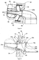
- Figure 4 illustrates a further embodiment in which protrusions 62 may have been provided on extenders 60.
- Extenders are elements that serve to increase the rotor diameter without increasing the rotor blade length. Roots of the rotor blades (not shown) may be attached at the edge of the extender. Inspection holes 64 may be provided to inspect the flexible couplings between protrusions 62 and a suitable part of the generator rotor.
- protrusions may also be provided on a coupling body (i.e. a separate component) which may be connected to the hub.
- figure 5 illustrates a further embodiment, in which a frame comprising a front frame 20a, a rear frame 20b and a middle frame 20c.
- middle frame 20c is adapted to carry out generator 30.
- Middle frame 20c furthermore has substantially the same length as the generator.
- An aspect of providing a frame (section) dedicated principally to carrying the generator is that this particular frame (section) and generator may be preassembled together; subsequently they may be assembled with the rear frame 20b. Installation of the wind turbine may thus be simplified.
- Rear frame 20b and middle frame 20c comprise suitable inward annular mounting flanges 26b and 26a respectively. These flanges 26a and 26b may be connected using a plurality of bolts 29b.
- Middle frame 20c furthermore comprises inward and outward mounting flanges at its forward end.
- Front frame 20a comprises corresponding mounting flanges.
- the front frame 20a and middle frame 20c may thus be connected using suitable bolts 29a.
- Middle frame 20c further comprises an outward mounting flange 27 at a central portion.
- Bolts 28 may be used to connect this mounting flange to generator stator 32.
- the generator stator may comprise a forward extending annular base upon which the generator rotor 33 is mounted. In this embodiment, a single bearing 35 is used.
- a substantially flexible coupling for transmitting the torque from the rotor to the generator rotor while substantially limiting the transfer of bending loads may be provided.
- Circumferentially arranged substantially axial protrusions 12 are attached to the rotor hub, and these axial protrusions extend into the generator rotor carrying structure, and one or more flexible elements may be arranged between the axial protrusions and said carrying structure.
- the generator stator is thus attached to the frame substantially in a plane perpendicular to the rotor's rotational axis, and the generator rotor is rotatably mounted on a part of the generator stator. Deformations of the generator may thus be avoided or reduced.
- the present invention is not limited in any way to the kind of bearings used to mount the hub on the frame or to mount the generator rotor on the generator stator.
- Suitable fluid bearings particularly hydrodynamic or hydrostatic bearings, may be employed.
- suitable rolling element bearings such as e.g. roller bearings, double-tapered roller bearings, or ball bearings may also be used.
- the bearings may further be purely radial bearings or radial and axial bearings.
- the present invention is furthermore not limited in any way to the kind of generator employed in the wind turbine. Any suitable kind of synchronous or asynchronous generator may be used.
- the generator rotor is provided with permanent magnets.
- the generator stator may be arranged radially outside the generator rotor. In other embodiments, the generator rotor may be arranged radially outside the generator stator, or the rotor and stator may e.g. be axially arranged.
- the frame supporting the rotor hub and generator may be formed of one integral part or may comprise two or more separate parts.
- the frame comprising a plurality of separate parts may have advantages for the installation of the wind turbine.
- the frame may furthermore be of any suitable shape and configuration: the frame may e.g. have a circular, elliptical, rectangular or other cross-section.
- the frame may be a forged component but may also be formed by e.g. a plurality of beams or a suitable truss structure.
Description
- The present invention relates to a wind turbine.
- Modern wind turbines are commonly used to supply electricity into the electrical grid. Wind turbines of this kind generally comprise a rotor with a rotor hub and a plurality of blades. The rotor is set into rotation under the influence of the wind on the blades. The rotation of the rotor shaft drives the generator rotor either directly ("directly driven") or through the use of a gearbox.
- Gearboxes form one of the most maintenance-intensive components of the wind turbine. They need to be inspected regularly and do not always fulfil their expected service life; the gearbox or some of its parts sometimes need to be replaced prematurely. This is due to the high loads and fluctuating loads to which a gearbox may be subjected. Particularly, the bending loads on the blades, which may be transmitted through the rotor shaft to the gearbox are damaging.
- Direct drive wind turbines such as known from e.g.
WO 2005/103489 , do not suffer from the problems related to the gearbox. However, since there is no speed increase, the generator shaft rotates very slowly. As a consequence, a large and relatively expensive generator is generally needed to be able to generate electricity in an effective way. Additionally, when bending loads and movements (and corresponding deformations) are transmitted through the rotor shaft to the generator, it may not be possible to control the air gap between generator rotor and generator stator. High bending loads can even cause structural damage to parts of the generator, e.g. its bearings. Replacement or repair of such generator parts may be very expensive due to the size and related cost of the generator and its components. - Also in the case of more integrated direct drive wind turbine designs, which lack a rotor shaft and which have a direct coupling between the hub or its blades and the generator's rotor (known from e.g.
DE 10255745 ), the bending moments and deformations are directly transmitted from the hub to the rotor and/or the stator, making it more difficult to minimize air gap variations. Another example is known fromWO 03/023943 - The cause of the transmission of the bending loads and deformations from the blades and hub to the generator lies in the wind turbine configuration. In most conventional wind turbines, the rotor hub is mounted on one end of the rotor shaft.
- The rotor shaft is rotatably mounted in a support structure within the nacelle on top of the wind turbine tower. The rotor thus forms an overhanging structure which transmits torque, but additionally transmits cyclical bending loads due to the loads on the blades and the weight of the hub and blades. These bending loads are (in the case of direct drive turbines) transmitted to the generator causing air gap variations.
-
WO 01/59296 - With this kind of configuration the loads due to the weight of hub and blades are transmitted more directly via the frame to the tower, whereas the rotor transmits mainly torque to the generator, thus substantially reducing (but not completely avoiding) undesired deformations in the generator. This may represent an improvement with respect to other prior art wind turbines, but air gap instability can still be a problem. Bending loads that are transmitted into the frame can cause deformations within the frame. Since the deformations along the length of the frame may vary under bending, the displacements experienced by the bearings of the rotor may vary. Also, the displacements experienced by the stator may be different from the displacements experienced by the rotor, thus causing air gap instability and deformations within the generator.
-
DE 10 2004 030 929 - At least one disadvantage associated with this configuration is the occurrence of high bending loads in the wind turbine tower. In larger offshore wind turbines, the weight of a generator may be close to or equal to the weight of a rotor. The rotor, with its long blades, will have to be arranged a minimum distance away from the tower to avoid the blades hitting the tower. By arranging the generator even further away from the tower, the bending loads in the tower may be very high.
- It is an object of the present invention to reduce at least some of the problems of the prior art. Further advantages of the invention will become apparent from its description.
- In a first aspect, the invention provides a wind turbine comprising a rotor, a generator and a tower, said rotor comprising a rotor hub and one or more rotor blades and said generator comprising a generator stator and a generator rotor, wherein the rotor hub is rotatably mounted on a frame and the generator and tower are arranged on the same side of the rotor, and the generator stator is attached to said frame substantially in a plane perpendicular to the rotor's rotational axis, and wherein the generator rotor is rotatably mounted on a part of the generator stator. Bending deformations experienced by the frame may vary particularly along the rotor's rotational axis (i.e. the frame's longitudinal axis).
- However, in a plane perpendicular to the rotational axis, these deformations will vary to a much lesser extent. Deformations of the frame will thus generally lead to a displacement (but not to a deformation) of the stator. Additionally, there is no direct contact between the generator rotor and the frame; the generator rotor is rotatably mounted on a part of the stator instead. In this aspect of the invention, the generator rotor will thus experience the same displacement as the generator stator. This will improve the air gap stability, since there is no relative displacement of the generator rotor with respect to the generator stator.
- In some embodiments, the generator rotor may be rotatably mounted on the generator stator through two bearings. In other embodiments, the generator rotor may be rotatably mounted on the generator stator through a single bearing.
- In some embodiments, the frame comprises at least two separate sections. For example, the frame may comprise a front frame and a rear frame, wherein the hub may be rotatably mounted on the front frame, and the rear frame may be rotatably mounted on a wind turbine tower. A single frame mounted upon the tower, carrying both the rotor hub and generator may be provided or such a frame may be split in two or more parts. A frame with two or more separate sections may have benefits during the installation of the wind turbine and may simplify manufacture. In these embodiments, the generator stator may be mounted either on the front or rear frame (or middle frame if provided), depending on the particular frame structure. In some embodiments, the frame comprises a front frame, middle frame and rear frame, and the hub is rotatably mounted on the front frame, the generator is mounted on the middle frame, and the rear frame is rotatably mounted on a wind turbine tower. These embodiments may have advantages with respect to the installation of the generator and middle frame.
- In some embodiments, torque is transmitted from the rotor to the generator rotor through a flexible coupling that substantially limits the transfer of bending loads. In these embodiments, the bending loads may be reduced significantly in the generator rotor. Combined with the fact that any deformations that may occur in the frame do not result in substantial deformations in the generator, air gap instability may be reduced in a very significant way.
- In some embodiments, one or more circumferentially arranged substantially axial protrusions are attached to said rotor, and said axial protrusions extend into the generator rotor carrying structure, and one or more flexible elements are arranged between one or more of said axial protrusions and said carrying structure. Optionally, said axial protrusions may be connected to or integrally formed with the rotor hub or extenders. Optionally, a coupling body is connected to the rotor hub, the coupling body comprising said axial protrusions. The flexible elements may e.g. be made from elastic or visco-elastic material.
- There are various ways in which a flexible coupling which transmits torque but substantially limits the transfer of bending loads can be provided. One preferred option is through protrusions attached to the hub that extend into a generator rotor carrying structure. Flexible elements may be provided to connect the protrusions to the rotor carrying structure. These flexible elements may take any suitable form and may derive their flexibility e.g. from their shape, material, positioning, mounting or combinations of these. They may be made from any suitable material, e.g. elastic or elastomer materials, or combinations of metals with elastomers or yet other suitable materials. Due to the arrangement of protrusions from the rotor extending into the generator rotor structure, the hub may be positioned closer to the tower, thus also reducing loads in the tower.
- Particular embodiments of the present invention will be described in the following, only by way of non-limiting examples, with reference to the appended drawings, in which:
-
Figure 1 illustrates a first embodiment of a wind turbine according to the present invention; -
Figure 2 illustrates a second embodiment of a wind turbine according to the present invention; -
Figure 3 illustrates a third embodiment of the present invention; -
Figure 4 illustrates a fourth embodiment of the present invention; -
Figure 5 illustrates a fifth embodiment of the present invention. -
Figure 1 illustrates a first embodiment of a wind turbine 1 according to the present invention. Wind turbine 1 comprises atower 50 upon which aframe 20 is rotatably mounted. In this embodiment,frame 20 comprises two separate sections: afront frame 20a and arear frame 20b.Reference sign 55 indicates the presence of a yaw mechanism, which allowsrear frame 20b to be rotated around the longitudinal axis of the wind turbine tower.Rear frame 20b andfront frame 20a comprise inward annular flanges.Bolts 24 may be used to connect these flanges. -
Rotor hub 10 is rotatably mounted onfront frame 20a throughbearings Rotor hub 10 carries a plurality of blades (not shown). Agenerator 30 is also mounted onframe 20.Generator housing 31 is connected throughbolts 22 to anannular flange 21 b provided onrear frame 20b. The generator stator is thus connected to the frame in a plane substantially perpendicular to the rotor's rotational axis. Schematically indicated withreference sign 34 is a suitable bearing, rotatably supporting agenerator rotor 33. Any suitable bearing may be used. -
Generator rotor 33 comprises (electro)magnetic means, which may include but are not limited to e.g. permanent magnets or windings. These (electro)magnetic means are carried by a carryingstructure 35, which is connected to thebearing 34 and thus can rotate with respect to the generator stator. - A
protrusion 12 is integrally formed withhub 10. Theprotrusion 12 may be flexibly coupled to generatorrotor carrying structure 35, thus limiting the transfer of bending loads. In some embodiments, this connection may also be rigid. - The connection of the stator in a plane perpendicular to the rotor's rotational axis, in combination with the lack of a direct connection between the generator rotor and the frame may reduce the air gap instability. A further reduction of air gap instability may be achieved with a flexible coupling between rotor and generator rotor, substantially avoiding the transfer of hub displacements and deformations to the generator rotor.
- All connections shown in this embodiment were schematically indicated with bolts, but it will be clear that many other fastening methods may also be used.
-
Figure 2 schematically illustrates a second embodiment of a wind turbine according to the present invention. Outwardannular flanges front frame 20a andrear frame 20b using bolts 24. A single bearing connected torear frame 20b using afastener 22 is again provided. The bearing rotatably supportsgenerator rotor 33. - In an alternative embodiment, the bearing 34 may be connected e.g. to
flange 26a offront frame 20a. -
Figure 3 illustrates a further alternative. In contrast to the previous embodiments shown,generator rotor 33 is rotatably supported uponstator 32 using twobearings generator stator 32 is once again connected torear frame 20b in a plane substantially perpendicular to the rotor's rotational axis. Aradially extending part 36 which forms part of the stator structure carrying (electro)magnetic means, may be used to connect to the frame. - An
annular base 39 extends forwardly from thisconnection supporting bearings generator housing 31 is arranged around thegenerator stator 32. - Also illustrated in
figure 3 is an example of how a flexible (e.g. elastic or elastomer)element 40 may be provided to connect protrusions integrally formed or connected with the hub with a generatorrotor carrying structure 35. This is just one example of a number of alternative ways in which a flexible coupling may be provided. -
Figure 4 illustrates a further embodiment in which protrusions 62 may have been provided onextenders 60. Extenders are elements that serve to increase the rotor diameter without increasing the rotor blade length. Roots of the rotor blades (not shown) may be attached at the edge of the extender. Inspection holes 64 may be provided to inspect the flexible couplings betweenprotrusions 62 and a suitable part of the generator rotor. - In yet further embodiments, protrusions may also be provided on a coupling body (i.e. a separate component) which may be connected to the hub.
- Finally,
figure 5 illustrates a further embodiment, in which a frame comprising afront frame 20a, arear frame 20b and amiddle frame 20c. In this embodiment,middle frame 20c is adapted to carry outgenerator 30.Middle frame 20c furthermore has substantially the same length as the generator. An aspect of providing a frame (section) dedicated principally to carrying the generator is that this particular frame (section) and generator may be preassembled together; subsequently they may be assembled with therear frame 20b. Installation of the wind turbine may thus be simplified. -
Rear frame 20b andmiddle frame 20c comprise suitable inward annular mountingflanges flanges bolts 29b. -
Middle frame 20c furthermore comprises inward and outward mounting flanges at its forward end.Front frame 20a comprises corresponding mounting flanges. Thefront frame 20a andmiddle frame 20c may thus be connected usingsuitable bolts 29a. -
Middle frame 20c further comprises an outward mountingflange 27 at a central portion.Bolts 28 may be used to connect this mounting flange togenerator stator 32. Similarly as infigure 3 , the generator stator may comprise a forward extending annular base upon which thegenerator rotor 33 is mounted. In this embodiment, asingle bearing 35 is used. - Similarly as in the embodiments of
figures 1 - 4 , a substantially flexible coupling for transmitting the torque from the rotor to the generator rotor while substantially limiting the transfer of bending loads may be provided. Circumferentially arranged substantiallyaxial protrusions 12 are attached to the rotor hub, and these axial protrusions extend into the generator rotor carrying structure, and one or more flexible elements may be arranged between the axial protrusions and said carrying structure. - In accordance with this embodiment, the generator stator is thus attached to the frame substantially in a plane perpendicular to the rotor's rotational axis, and the generator rotor is rotatably mounted on a part of the generator stator. Deformations of the generator may thus be avoided or reduced.
- The present invention is not limited in any way to the kind of bearings used to mount the hub on the frame or to mount the generator rotor on the generator stator. Suitable fluid bearings, particularly hydrodynamic or hydrostatic bearings, may be employed. Alternatively, suitable rolling element bearings, such as e.g. roller bearings, double-tapered roller bearings, or ball bearings may also be used.
- The bearings may further be purely radial bearings or radial and axial bearings.
- The present invention is furthermore not limited in any way to the kind of generator employed in the wind turbine. Any suitable kind of synchronous or asynchronous generator may be used. In one preferred embodiment of the present invention, the generator rotor is provided with permanent magnets. The generator stator may be arranged radially outside the generator rotor. In other embodiments, the generator rotor may be arranged radially outside the generator stator, or the rotor and stator may e.g. be axially arranged.
- Also the frame supporting the rotor hub and generator may be formed of one integral part or may comprise two or more separate parts. The frame comprising a plurality of separate parts may have advantages for the installation of the wind turbine. The frame may furthermore be of any suitable shape and configuration: the frame may e.g. have a circular, elliptical, rectangular or other cross-section.
- The frame may be a forged component but may also be formed by e.g. a plurality of beams or a suitable truss structure.
- Although this invention has been disclosed in the context of certain preferred embodiments and examples, it will be understood by those skilled in the art that the present invention extends beyond the specifically disclosed embodiments to other alternative embodiments and/or uses of the invention and obvious modifications and equivalents thereof. Thus, it is intended that the scope of the present invention herein disclosed should not be limited by the particular disclosed embodiments described before, but should be determined only by a fair reading of the claims that follow.
Claims (15)
- Wind turbine (1) comprising a rotor, a generator (30) and a tower (50), said rotor comprising a rotor hub (10) and one or more rotor blades and said generator (30) comprising a generator stator (32) and a generator rotor (33), wherein:the rotor hub (10) is rotatably mounted on a frame (20, 20a, 20b, 20c) and the generator (30) and tower (50) are arranged on the same side of the rotor, andthe generator rotor (33) is rotatably mounted on a part of the generator stator (32), characterised in that the generator stator (32) is attached to said frame (20, 20a, 20b, 20c) substantially in a plane perpendicular to the rotor's rotational axis.
- Wind turbine (1) according to claim 1, wherein the generator rotor (33) is rotatably mounted on the generator stator (32) through two bearings (34a; 34b).
- Wind turbine (1) according to claim 1, wherein the generator rotor (33) is rotatably mounted on the generator stator (32) through a single bearing (34) and wherein said single bearing (34) is, optionally, a double tapered roller bearing.
- Wind turbine (1) according to any previous claim, wherein the frame (20) comprises at least two separate frame sections (20a, 20b).
- Wind turbine (1) according to claim 4, wherein the frame (20) comprises a front frame (20a) and a rear frame (20b), and wherein the hub (10) is rotatably mounted on the front frame (20a), and the rear frame (20b) is rotatably mounted on a wind turbine tower (50), and wherein, the generator stator (32) is, optionally, mounted on the rear frame (20b).
- Wind turbine (1) according to claim 4, wherein the frame (20) comprises a front frame (20a), middle frame (20c) and rear frame (20b), and wherein the hub (10) is rotatably mounted on the front frame (20a), the generator (30) is mounted on the middle frame (20c), and the rear frame (20b) is rotatably mounted on a wind turbine tower (50).
- Wind turbine (1) according to claim 6, wherein the middle frame (20c) has substantially the same length as the generator (30).
- Wind turbine (1) according to any previous claim, further comprising a flexible coupling for transmitting the torque from the rotor to the generator rotor (33) while substantially limiting the transfer of bending loads.
- Wind turbine (1) according to claim 8, wherein one or more circumferentially arranged substantially axial protrusions (12) are attached to said rotor, and
said axial protrusions (12, 62) extend into the generator rotor carrying structure (35), and
one or more flexible elements (40) are arranged between one or more of said axial protrusions (12, 62) and said carrying structure (35). - Wind turbine (1) according to claim 9, wherein said axial protrusions (12, 62) are connected to or integrally formed with the rotor hub (10).
- Wind turbine (1) according to claim 9, wherein the one or more blades are connected to the rotor hub (10) with extenders (60), and said axial protrusions (62) are connected to or integrally formed with said extenders (60).
- Wind turbine (1) according to claim 9, wherein a coupling body is connected to the rotor hub (10), the coupling body comprising said axial protrusions (12, 62).
- Wind turbine (1) according to any of claims 9 - 12, wherein said flexible elements (40) are made from elastic or visco-elastic material.
- Wind turbine (1) according to any previous claim, wherein the generator rotor (33) is arranged radially inside of the generator stator (32).
- Wind turbine (1) according to any previous claim, wherein the generator rotor (33) carries a plurality of permanent magnets.
Priority Applications (1)
| Application Number | Priority Date | Filing Date | Title |
|---|---|---|---|
| EP11704599.7A EP2593674B8 (en) | 2010-07-12 | 2011-02-14 | Wind turbine |
Applications Claiming Priority (3)
| Application Number | Priority Date | Filing Date | Title |
|---|---|---|---|
| EP10382190 | 2010-07-12 | ||
| PCT/EP2011/052153 WO2012007186A1 (en) | 2010-07-12 | 2011-02-14 | Wind turbine |
| EP11704599.7A EP2593674B8 (en) | 2010-07-12 | 2011-02-14 | Wind turbine |
Publications (3)
| Publication Number | Publication Date |
|---|---|
| EP2593674A1 EP2593674A1 (en) | 2013-05-22 |
| EP2593674B1 true EP2593674B1 (en) | 2016-09-07 |
| EP2593674B8 EP2593674B8 (en) | 2016-10-19 |
Family
ID=43066596
Family Applications (1)
| Application Number | Title | Priority Date | Filing Date |
|---|---|---|---|
| EP11704599.7A Active EP2593674B8 (en) | 2010-07-12 | 2011-02-14 | Wind turbine |
Country Status (6)
| Country | Link |
|---|---|
| US (1) | US8994205B2 (en) |
| EP (1) | EP2593674B8 (en) |
| KR (1) | KR20130056884A (en) |
| CN (1) | CN102985690B (en) |
| DK (1) | DK2593674T3 (en) |
| WO (1) | WO2012007186A1 (en) |
Families Citing this family (6)
| Publication number | Priority date | Publication date | Assignee | Title |
|---|---|---|---|---|
| DE102007012408A1 (en) * | 2007-03-15 | 2008-09-18 | Aerodyn Engineering Gmbh | Wind turbines with load-transmitting components |
| US20150322922A1 (en) * | 2012-01-17 | 2015-11-12 | United Technologies Corporation | Generator with stator supported on rotor |
| DK2657519T3 (en) * | 2012-04-26 | 2015-09-07 | Siemens Ag | Windmill |
| EP2937556B1 (en) * | 2014-04-25 | 2018-02-21 | Siemens Aktiengesellschaft | Flange of a wind turbine |
| CN105464899B (en) * | 2015-12-15 | 2018-07-31 | 北京金风科创风电设备有限公司 | Wind driven generator and wind driven generator set |
| DE102017114584A1 (en) * | 2017-06-29 | 2019-01-03 | Wobben Properties Gmbh | Wind turbine rotary joint, and wind turbine with selbiger |
Family Cites Families (19)
| Publication number | Priority date | Publication date | Assignee | Title |
|---|---|---|---|---|
| SE515712C3 (en) | 2000-02-10 | 2001-10-23 | Abb Ab | Electric power generating device |
| DE10044262A1 (en) | 2000-09-07 | 2002-03-21 | Stephan Joeckel | Gear-less wind power system has blade angle adjustment for active vibration damping in drive train, and no mechanical gears but slow synchronous generator directly driven by wind wheel |
| ITBZ20010043A1 (en) * | 2001-09-13 | 2003-03-13 | High Technology Invest Bv | ELECTRIC GENERATOR OPERATED BY WIND ENERGY. |
| US7042109B2 (en) * | 2002-08-30 | 2006-05-09 | Gabrys Christopher W | Wind turbine |
| DE10255745A1 (en) | 2002-11-28 | 2004-06-17 | Jörck, Hartmut | Directly driven wind power system with bearing integrated in generator has generator rotor or hub radially between and/or axially adjacent to generator stator and rotor and supported on stator housing |
| US7431567B1 (en) * | 2003-05-30 | 2008-10-07 | Northern Power Systems Inc. | Wind turbine having a direct-drive drivetrain |
| US7075192B2 (en) | 2004-04-19 | 2006-07-11 | Northern Power Systems, Inc. | Direct drive wind turbine |
| DE102004030929B3 (en) | 2004-06-25 | 2005-10-20 | Repower Systems Ag | Wind power plant has generator installed on rotor side facing away from pod, and generator stator is fastened on journal extending from pod through rotor hub and serving as bearing for rotor |
| US7180204B2 (en) | 2005-01-07 | 2007-02-20 | General Electric Company | Method and apparatus for wind turbine air gap control |
| CN1727672A (en) * | 2005-07-14 | 2006-02-01 | 潍坊中云机器有限公司 | Drive unit with variable airscrew pitch of wind driven generator |
| KR100752510B1 (en) * | 2006-04-14 | 2007-08-29 | 유니슨 주식회사 | Wind energy converter with single main bearing |
| BE1017135A3 (en) * | 2006-05-11 | 2008-03-04 | Hansen Transmissions Int | A GEARBOX FOR A WIND TURBINE. |
| US7528497B2 (en) * | 2006-07-11 | 2009-05-05 | Hamilton Sundstrand Corporation | Wind-turbine with load-carrying skin |
| ES2746975T3 (en) | 2008-10-03 | 2020-03-09 | Ge Renewable Tech Wind Bv | Procedure and system to align a component of a wind turbine |
| GB0818610D0 (en) * | 2008-10-10 | 2008-11-19 | Sway As | Wind turbine rotor and wind turbine |
| ES2451000T3 (en) * | 2010-03-29 | 2014-03-26 | Alstom Renovables España, S.L. | Wind turbine |
| EP2397690A1 (en) * | 2010-06-21 | 2011-12-21 | Envision Energy (Denmark) ApS | Flexible shaft wind turbine |
| DK2416009T3 (en) * | 2010-08-06 | 2013-07-15 | Alstom Wind Slu | Directly operated wind turbine and method for controlling air gap |
| US20110143880A1 (en) * | 2010-12-01 | 2011-06-16 | General Electric Company | Drivetrain for generator in wind turbine |
-
2011
- 2011-02-14 DK DK11704599.7T patent/DK2593674T3/en active
- 2011-02-14 EP EP11704599.7A patent/EP2593674B8/en active Active
- 2011-02-14 CN CN201180034260.5A patent/CN102985690B/en active Active
- 2011-02-14 KR KR1020137001169A patent/KR20130056884A/en not_active Application Discontinuation
- 2011-02-14 WO PCT/EP2011/052153 patent/WO2012007186A1/en active Application Filing
- 2011-02-14 US US13/387,209 patent/US8994205B2/en active Active
Also Published As
| Publication number | Publication date |
|---|---|
| EP2593674B8 (en) | 2016-10-19 |
| CN102985690B (en) | 2016-04-20 |
| WO2012007186A1 (en) | 2012-01-19 |
| CN102985690A (en) | 2013-03-20 |
| KR20130056884A (en) | 2013-05-30 |
| US20120161449A1 (en) | 2012-06-28 |
| DK2593674T3 (en) | 2017-01-02 |
| EP2593674A1 (en) | 2013-05-22 |
| US8994205B2 (en) | 2015-03-31 |
Similar Documents
| Publication | Publication Date | Title |
|---|---|---|
| EP2372150B1 (en) | Wind turbine | |
| EP2593673B1 (en) | Wind turbine | |
| EP2372151B1 (en) | Wind turbine | |
| EP2593674B1 (en) | Wind turbine | |
| EP2553264B1 (en) | Wind turbine | |
| EP2063114A1 (en) | Wind turbine | |
| EP2474735B1 (en) | Mounting arrangement for pitch gear | |
| EP2530301A1 (en) | Blade root stiffening element and method of mounting a blade having said root stiffening element | |
| US20110211962A1 (en) | Drivetrain for generator in wind turbine | |
| EP3428449B1 (en) | Drivetrain for a wind turbine and method for positioning a main bearing of said drivetrain | |
| EP2474736A1 (en) | Wind driven generator | |
| US8436486B2 (en) | Power train for a wind turbine | |
| EP2532882A1 (en) | System and methods for assembling a wind turbine with a pitch assembly |
Legal Events
| Date | Code | Title | Description |
|---|---|---|---|
| PUAI | Public reference made under article 153(3) epc to a published international application that has entered the european phase |
Free format text: ORIGINAL CODE: 0009012 |
|
| 17P | Request for examination filed |
Effective date: 20130212 |
|
| AK | Designated contracting states |
Kind code of ref document: A1 Designated state(s): AL AT BE BG CH CY CZ DE DK EE ES FI FR GB GR HR HU IE IS IT LI LT LU LV MC MK MT NL NO PL PT RO RS SE SI SK SM TR |
|
| DAX | Request for extension of the european patent (deleted) | ||
| REG | Reference to a national code |
Ref country code: DE Ref legal event code: R079 Ref document number: 602011030077 Country of ref document: DE Free format text: PREVIOUS MAIN CLASS: F03D0011020000 Ipc: F03D0080000000 |
|
| RIC1 | Information provided on ipc code assigned before grant |
Ipc: F03D 80/00 20160101AFI20160209BHEP |
|
| GRAP | Despatch of communication of intention to grant a patent |
Free format text: ORIGINAL CODE: EPIDOSNIGR1 |
|
| INTG | Intention to grant announced |
Effective date: 20160321 |
|
| GRAS | Grant fee paid |
Free format text: ORIGINAL CODE: EPIDOSNIGR3 |
|
| GRAA | (expected) grant |
Free format text: ORIGINAL CODE: 0009210 |
|
| AK | Designated contracting states |
Kind code of ref document: B1 Designated state(s): AL AT BE BG CH CY CZ DE DK EE ES FI FR GB GR HR HU IE IS IT LI LT LU LV MC MK MT NL NO PL PT RO RS SE SI SK SM TR |
|
| REG | Reference to a national code |
Ref country code: GB Ref legal event code: FG4D |
|
| REG | Reference to a national code |
Ref country code: CH Ref legal event code: EP |
|
| RAP2 | Party data changed (patent owner data changed or rights of a patent transferred) |
Owner name: ALSTOM RENEWABLE TECHNOLOGIES |
|
| REG | Reference to a national code |
Ref country code: IE Ref legal event code: FG4D |
|
| REG | Reference to a national code |
Ref country code: AT Ref legal event code: REF Ref document number: 827130 Country of ref document: AT Kind code of ref document: T Effective date: 20161015 |
|
| REG | Reference to a national code |
Ref country code: DE Ref legal event code: R096 Ref document number: 602011030077 Country of ref document: DE |
|
| REG | Reference to a national code |
Ref country code: DK Ref legal event code: T3 Effective date: 20161227 |
|
| REG | Reference to a national code |
Ref country code: LT Ref legal event code: MG4D |
|
| REG | Reference to a national code |
Ref country code: NL Ref legal event code: MP Effective date: 20160907 |
|
| PG25 | Lapsed in a contracting state [announced via postgrant information from national office to epo] |
Ref country code: RS Free format text: LAPSE BECAUSE OF FAILURE TO SUBMIT A TRANSLATION OF THE DESCRIPTION OR TO PAY THE FEE WITHIN THE PRESCRIBED TIME-LIMIT Effective date: 20160907 Ref country code: NO Free format text: LAPSE BECAUSE OF FAILURE TO SUBMIT A TRANSLATION OF THE DESCRIPTION OR TO PAY THE FEE WITHIN THE PRESCRIBED TIME-LIMIT Effective date: 20161207 Ref country code: FI Free format text: LAPSE BECAUSE OF FAILURE TO SUBMIT A TRANSLATION OF THE DESCRIPTION OR TO PAY THE FEE WITHIN THE PRESCRIBED TIME-LIMIT Effective date: 20160907 Ref country code: HR Free format text: LAPSE BECAUSE OF FAILURE TO SUBMIT A TRANSLATION OF THE DESCRIPTION OR TO PAY THE FEE WITHIN THE PRESCRIBED TIME-LIMIT Effective date: 20160907 Ref country code: LT Free format text: LAPSE BECAUSE OF FAILURE TO SUBMIT A TRANSLATION OF THE DESCRIPTION OR TO PAY THE FEE WITHIN THE PRESCRIBED TIME-LIMIT Effective date: 20160907 |
|
| REG | Reference to a national code |
Ref country code: AT Ref legal event code: MK05 Ref document number: 827130 Country of ref document: AT Kind code of ref document: T Effective date: 20160907 |
|
| REG | Reference to a national code |
Ref country code: FR Ref legal event code: PLFP Year of fee payment: 7 |
|
| PG25 | Lapsed in a contracting state [announced via postgrant information from national office to epo] |
Ref country code: NL Free format text: LAPSE BECAUSE OF FAILURE TO SUBMIT A TRANSLATION OF THE DESCRIPTION OR TO PAY THE FEE WITHIN THE PRESCRIBED TIME-LIMIT Effective date: 20160907 Ref country code: GR Free format text: LAPSE BECAUSE OF FAILURE TO SUBMIT A TRANSLATION OF THE DESCRIPTION OR TO PAY THE FEE WITHIN THE PRESCRIBED TIME-LIMIT Effective date: 20161208 Ref country code: LV Free format text: LAPSE BECAUSE OF FAILURE TO SUBMIT A TRANSLATION OF THE DESCRIPTION OR TO PAY THE FEE WITHIN THE PRESCRIBED TIME-LIMIT Effective date: 20160907 Ref country code: ES Free format text: LAPSE BECAUSE OF FAILURE TO SUBMIT A TRANSLATION OF THE DESCRIPTION OR TO PAY THE FEE WITHIN THE PRESCRIBED TIME-LIMIT Effective date: 20160907 Ref country code: SE Free format text: LAPSE BECAUSE OF FAILURE TO SUBMIT A TRANSLATION OF THE DESCRIPTION OR TO PAY THE FEE WITHIN THE PRESCRIBED TIME-LIMIT Effective date: 20160907 |
|
| REG | Reference to a national code |
Ref country code: DE Ref legal event code: R081 Ref document number: 602011030077 Country of ref document: DE Owner name: ALSTOM RENEWABLE TECHNOLOGIES, FR Free format text: FORMER OWNER: ALSTOM WIND, S.L.U., BARCELONA, ES Ref country code: DE Ref legal event code: R081 Ref document number: 602011030077 Country of ref document: DE Owner name: GE RENEWABLE TECHNOLOGIES WIND B.V., NL Free format text: FORMER OWNER: ALSTOM WIND, S.L.U., BARCELONA, ES |
|
| PG25 | Lapsed in a contracting state [announced via postgrant information from national office to epo] |
Ref country code: RO Free format text: LAPSE BECAUSE OF FAILURE TO SUBMIT A TRANSLATION OF THE DESCRIPTION OR TO PAY THE FEE WITHIN THE PRESCRIBED TIME-LIMIT Effective date: 20160907 Ref country code: EE Free format text: LAPSE BECAUSE OF FAILURE TO SUBMIT A TRANSLATION OF THE DESCRIPTION OR TO PAY THE FEE WITHIN THE PRESCRIBED TIME-LIMIT Effective date: 20160907 |
|
| PG25 | Lapsed in a contracting state [announced via postgrant information from national office to epo] |
Ref country code: SM Free format text: LAPSE BECAUSE OF FAILURE TO SUBMIT A TRANSLATION OF THE DESCRIPTION OR TO PAY THE FEE WITHIN THE PRESCRIBED TIME-LIMIT Effective date: 20160907 Ref country code: AT Free format text: LAPSE BECAUSE OF FAILURE TO SUBMIT A TRANSLATION OF THE DESCRIPTION OR TO PAY THE FEE WITHIN THE PRESCRIBED TIME-LIMIT Effective date: 20160907 Ref country code: IS Free format text: LAPSE BECAUSE OF FAILURE TO SUBMIT A TRANSLATION OF THE DESCRIPTION OR TO PAY THE FEE WITHIN THE PRESCRIBED TIME-LIMIT Effective date: 20170107 Ref country code: SK Free format text: LAPSE BECAUSE OF FAILURE TO SUBMIT A TRANSLATION OF THE DESCRIPTION OR TO PAY THE FEE WITHIN THE PRESCRIBED TIME-LIMIT Effective date: 20160907 Ref country code: CZ Free format text: LAPSE BECAUSE OF FAILURE TO SUBMIT A TRANSLATION OF THE DESCRIPTION OR TO PAY THE FEE WITHIN THE PRESCRIBED TIME-LIMIT Effective date: 20160907 Ref country code: PL Free format text: LAPSE BECAUSE OF FAILURE TO SUBMIT A TRANSLATION OF THE DESCRIPTION OR TO PAY THE FEE WITHIN THE PRESCRIBED TIME-LIMIT Effective date: 20160907 Ref country code: BE Free format text: LAPSE BECAUSE OF FAILURE TO SUBMIT A TRANSLATION OF THE DESCRIPTION OR TO PAY THE FEE WITHIN THE PRESCRIBED TIME-LIMIT Effective date: 20160907 Ref country code: BG Free format text: LAPSE BECAUSE OF FAILURE TO SUBMIT A TRANSLATION OF THE DESCRIPTION OR TO PAY THE FEE WITHIN THE PRESCRIBED TIME-LIMIT Effective date: 20161207 Ref country code: PT Free format text: LAPSE BECAUSE OF FAILURE TO SUBMIT A TRANSLATION OF THE DESCRIPTION OR TO PAY THE FEE WITHIN THE PRESCRIBED TIME-LIMIT Effective date: 20170109 |
|
| REG | Reference to a national code |
Ref country code: DE Ref legal event code: R097 Ref document number: 602011030077 Country of ref document: DE |
|
| PG25 | Lapsed in a contracting state [announced via postgrant information from national office to epo] |
Ref country code: IT Free format text: LAPSE BECAUSE OF FAILURE TO SUBMIT A TRANSLATION OF THE DESCRIPTION OR TO PAY THE FEE WITHIN THE PRESCRIBED TIME-LIMIT Effective date: 20160907 |
|
| PLBE | No opposition filed within time limit |
Free format text: ORIGINAL CODE: 0009261 |
|
| STAA | Information on the status of an ep patent application or granted ep patent |
Free format text: STATUS: NO OPPOSITION FILED WITHIN TIME LIMIT |
|
| 26N | No opposition filed |
Effective date: 20170608 |
|
| PG25 | Lapsed in a contracting state [announced via postgrant information from national office to epo] |
Ref country code: SI Free format text: LAPSE BECAUSE OF FAILURE TO SUBMIT A TRANSLATION OF THE DESCRIPTION OR TO PAY THE FEE WITHIN THE PRESCRIBED TIME-LIMIT Effective date: 20160907 |
|
| PG25 | Lapsed in a contracting state [announced via postgrant information from national office to epo] |
Ref country code: MC Free format text: LAPSE BECAUSE OF FAILURE TO SUBMIT A TRANSLATION OF THE DESCRIPTION OR TO PAY THE FEE WITHIN THE PRESCRIBED TIME-LIMIT Effective date: 20160907 |
|
| REG | Reference to a national code |
Ref country code: CH Ref legal event code: PL |
|
| PG25 | Lapsed in a contracting state [announced via postgrant information from national office to epo] |
Ref country code: LI Free format text: LAPSE BECAUSE OF NON-PAYMENT OF DUE FEES Effective date: 20170228 Ref country code: CH Free format text: LAPSE BECAUSE OF NON-PAYMENT OF DUE FEES Effective date: 20170228 |
|
| REG | Reference to a national code |
Ref country code: DE Ref legal event code: R081 Ref document number: 602011030077 Country of ref document: DE Owner name: GE RENEWABLE TECHNOLOGIES WIND B.V., NL Free format text: FORMER OWNER: ALSTOM RENEWABLE TECHNOLOGIES, GRENOBLE, FR |
|
| PG25 | Lapsed in a contracting state [announced via postgrant information from national office to epo] |
Ref country code: LU Free format text: LAPSE BECAUSE OF NON-PAYMENT OF DUE FEES Effective date: 20170214 |
|
| REG | Reference to a national code |
Ref country code: FR Ref legal event code: PLFP Year of fee payment: 8 |
|
| REG | Reference to a national code |
Ref country code: FR Ref legal event code: CD Owner name: GE RENEWABLE TECHNOLOGIES WIND B.V., NL Effective date: 20180219 Ref country code: FR Ref legal event code: TP Owner name: GE RENEWABLE TECHNOLOGIES WIND B.V., NL Effective date: 20180219 |
|
| REG | Reference to a national code |
Ref country code: GB Ref legal event code: 732E Free format text: REGISTERED BETWEEN 20180315 AND 20180326 |
|
| PG25 | Lapsed in a contracting state [announced via postgrant information from national office to epo] |
Ref country code: MT Free format text: LAPSE BECAUSE OF NON-PAYMENT OF DUE FEES Effective date: 20170214 |
|
| PG25 | Lapsed in a contracting state [announced via postgrant information from national office to epo] |
Ref country code: AL Free format text: LAPSE BECAUSE OF FAILURE TO SUBMIT A TRANSLATION OF THE DESCRIPTION OR TO PAY THE FEE WITHIN THE PRESCRIBED TIME-LIMIT Effective date: 20160907 |
|
| REG | Reference to a national code |
Ref country code: IE Ref legal event code: MM4A |
|
| PG25 | Lapsed in a contracting state [announced via postgrant information from national office to epo] |
Ref country code: IE Free format text: LAPSE BECAUSE OF NON-PAYMENT OF DUE FEES Effective date: 20170214 |
|
| PG25 | Lapsed in a contracting state [announced via postgrant information from national office to epo] |
Ref country code: HU Free format text: LAPSE BECAUSE OF FAILURE TO SUBMIT A TRANSLATION OF THE DESCRIPTION OR TO PAY THE FEE WITHIN THE PRESCRIBED TIME-LIMIT; INVALID AB INITIO Effective date: 20110214 |
|
| PG25 | Lapsed in a contracting state [announced via postgrant information from national office to epo] |
Ref country code: CY Free format text: LAPSE BECAUSE OF NON-PAYMENT OF DUE FEES Effective date: 20160907 |
|
| PG25 | Lapsed in a contracting state [announced via postgrant information from national office to epo] |
Ref country code: MK Free format text: LAPSE BECAUSE OF FAILURE TO SUBMIT A TRANSLATION OF THE DESCRIPTION OR TO PAY THE FEE WITHIN THE PRESCRIBED TIME-LIMIT Effective date: 20160907 |
|
| PG25 | Lapsed in a contracting state [announced via postgrant information from national office to epo] |
Ref country code: TR Free format text: LAPSE BECAUSE OF FAILURE TO SUBMIT A TRANSLATION OF THE DESCRIPTION OR TO PAY THE FEE WITHIN THE PRESCRIBED TIME-LIMIT Effective date: 20160907 |
|
| PGFP | Annual fee paid to national office [announced via postgrant information from national office to epo] |
Ref country code: FR Payment date: 20230119 Year of fee payment: 13 Ref country code: DK Payment date: 20230119 Year of fee payment: 13 |
|
| PGFP | Annual fee paid to national office [announced via postgrant information from national office to epo] |
Ref country code: GB Payment date: 20230120 Year of fee payment: 13 Ref country code: DE Payment date: 20230119 Year of fee payment: 13 |
|
| P01 | Opt-out of the competence of the unified patent court (upc) registered |
Effective date: 20230529 |