EP2593214B1 - Horizontal mixer with center-angled blades - Google Patents
Horizontal mixer with center-angled blades Download PDFInfo
- Publication number
- EP2593214B1 EP2593214B1 EP11749961.6A EP11749961A EP2593214B1 EP 2593214 B1 EP2593214 B1 EP 2593214B1 EP 11749961 A EP11749961 A EP 11749961A EP 2593214 B1 EP2593214 B1 EP 2593214B1
- Authority
- EP
- European Patent Office
- Prior art keywords
- blade
- horizontal mixer
- blades
- container
- rotational axis
- Prior art date
- Legal status (The legal status is an assumption and is not a legal conclusion. Google has not performed a legal analysis and makes no representation as to the accuracy of the status listed.)
- Not-in-force
Links
- 239000002002 slurry Substances 0.000 claims description 66
- 239000012530 fluid Substances 0.000 claims description 44
- 239000002245 particle Substances 0.000 claims description 23
- PNEYBMLMFCGWSK-UHFFFAOYSA-N aluminium oxide Inorganic materials [O-2].[O-2].[O-2].[Al+3].[Al+3] PNEYBMLMFCGWSK-UHFFFAOYSA-N 0.000 description 9
- GKLVYJBZJHMRIY-OUBTZVSYSA-N Technetium-99 Chemical compound [99Tc] GKLVYJBZJHMRIY-OUBTZVSYSA-N 0.000 description 4
- 239000011521 glass Substances 0.000 description 4
- 238000004519 manufacturing process Methods 0.000 description 4
- 229940056501 technetium 99m Drugs 0.000 description 4
- 238000009826 distribution Methods 0.000 description 3
- 239000000463 material Substances 0.000 description 3
- 230000003068 static effect Effects 0.000 description 3
- XLYOFNOQVPJJNP-UHFFFAOYSA-N water Chemical compound O XLYOFNOQVPJJNP-UHFFFAOYSA-N 0.000 description 3
- 238000012512 characterization method Methods 0.000 description 2
- 238000001311 chemical methods and process Methods 0.000 description 2
- 238000003745 diagnosis Methods 0.000 description 2
- 230000001939 inductive effect Effects 0.000 description 2
- 239000007788 liquid Substances 0.000 description 2
- 238000000034 method Methods 0.000 description 2
- 238000009206 nuclear medicine Methods 0.000 description 2
- 230000002572 peristaltic effect Effects 0.000 description 2
- 239000002904 solvent Substances 0.000 description 2
- 239000000126 substance Substances 0.000 description 2
- ZOKXTWBITQBERF-AKLPVKDBSA-N Molybdenum Mo-99 Chemical compound [99Mo] ZOKXTWBITQBERF-AKLPVKDBSA-N 0.000 description 1
- 238000013375 chromatographic separation Methods 0.000 description 1
- 239000012501 chromatography medium Substances 0.000 description 1
- 238000004440 column chromatography Methods 0.000 description 1
- 150000001875 compounds Chemical class 0.000 description 1
- 238000010276 construction Methods 0.000 description 1
- 239000012153 distilled water Substances 0.000 description 1
- 238000011177 media preparation Methods 0.000 description 1
- 239000000203 mixture Substances 0.000 description 1
- 229950009740 molybdenum mo-99 Drugs 0.000 description 1
- TWNQGVIAIRXVLR-UHFFFAOYSA-N oxo(oxoalumanyloxy)alumane Chemical compound O=[Al]O[Al]=O TWNQGVIAIRXVLR-UHFFFAOYSA-N 0.000 description 1
- 238000012856 packing Methods 0.000 description 1
- 239000013618 particulate matter Substances 0.000 description 1
- 230000002250 progressing effect Effects 0.000 description 1
- 230000001737 promoting effect Effects 0.000 description 1
- 238000007789 sealing Methods 0.000 description 1
- 238000009987 spinning Methods 0.000 description 1
- 229910052713 technetium Inorganic materials 0.000 description 1
- GKLVYJBZJHMRIY-UHFFFAOYSA-N technetium atom Chemical compound [Tc] GKLVYJBZJHMRIY-UHFFFAOYSA-N 0.000 description 1
Images



Classifications
-
- B—PERFORMING OPERATIONS; TRANSPORTING
- B01—PHYSICAL OR CHEMICAL PROCESSES OR APPARATUS IN GENERAL
- B01F—MIXING, e.g. DISSOLVING, EMULSIFYING OR DISPERSING
- B01F29/00—Mixers with rotating receptacles
- B01F29/60—Mixers with rotating receptacles rotating about a horizontal or inclined axis, e.g. drum mixers
- B01F29/63—Mixers with rotating receptacles rotating about a horizontal or inclined axis, e.g. drum mixers with fixed bars, i.e. stationary, or fixed on the receptacle
-
- B—PERFORMING OPERATIONS; TRANSPORTING
- B01—PHYSICAL OR CHEMICAL PROCESSES OR APPARATUS IN GENERAL
- B01F—MIXING, e.g. DISSOLVING, EMULSIFYING OR DISPERSING
- B01F23/00—Mixing according to the phases to be mixed, e.g. dispersing or emulsifying
- B01F23/50—Mixing liquids with solids
-
- B—PERFORMING OPERATIONS; TRANSPORTING
- B01—PHYSICAL OR CHEMICAL PROCESSES OR APPARATUS IN GENERAL
- B01F—MIXING, e.g. DISSOLVING, EMULSIFYING OR DISPERSING
- B01F25/00—Flow mixers; Mixers for falling materials, e.g. solid particles
- B01F25/50—Circulation mixers, e.g. wherein at least part of the mixture is discharged from and reintroduced into a receptacle
-
- B—PERFORMING OPERATIONS; TRANSPORTING
- B01—PHYSICAL OR CHEMICAL PROCESSES OR APPARATUS IN GENERAL
- B01F—MIXING, e.g. DISSOLVING, EMULSIFYING OR DISPERSING
- B01F29/00—Mixers with rotating receptacles
- B01F29/60—Mixers with rotating receptacles rotating about a horizontal or inclined axis, e.g. drum mixers
- B01F29/61—Mixers with rotating receptacles rotating about a horizontal or inclined axis, e.g. drum mixers comprising liquid spraying devices
Definitions
- the present invention generally relates to the field of mixers and, more particularly, to how blades may be incorporated by a mixer to enhance mixing.
- mixers exist and for a variety applications.
- One type of mixer uses a vertically-oriented shaft with blades attached thereto, and which is disposed in an appropriate housing. The shaft and blades rotate relative to the housing.
- the abrasive particles tend to chip the blades such that these blade chips become part of the abrasive slurry.
- centrifugal forces create a distribution of particles within the slurry - particles are distributed in the slurry based upon their respective weights progressing away from the rotating shaft (i.e., heavier particles will be directed further away from the vertically oriented, rotating shaft than lighter particles). Although this may be acceptable for certain applications, other applications could benefit for a more homogenous distribution of particles within the slurry.
- US2009/0073798 describes a batch mixer comprising a mixing drum rotatable about a longitudinal axis extending between an inlet opening and a discharge opening at opposing ends of the drum.
- US1,093,723 describes a rotary mixing machine according to the preamble of claim 1 comprising a revolvable mixing drum provided with a plurality of mixing blades or battles arranged to deliver materials to a discharge chute at one side of the drum.
- a first aspect of the present invention is embodied by a horizontal mixer for producing a slurry from which isotopes may be produced.
- This mixer includes a container or tumbler that is able to rotate about an at least substantially horizontally disposed rotational axis, an inner sidewall that is disposed about this rotational axis (e.g., extends a full 360° about this rotational axis), and a mixing chamber that is at least partially defined by this inner sidewall.
- Multiple blades or fins extend from the inner sidewall of the container and in the direction of an interior of the mixing chamber (e.g., defining protrusions on the inner sidewall). These blades are oriented to direct fluid toward an outlet from the mixing chamber for at least a certain rotational angle and during rotation of the container in a first rotational direction about its rotational axis.
- This mixer includes a container or tumbler having first and second container/tumbler ends that are spaced along an at least substantially horizontally disposed rotational axis of the container.
- the inner sidewall of the container is disposed about its rotational axis and may extend between the first and second container ends.
- the first and second container ends, along with the inner sidewall, may at least partially define a mixing chamber for the container.
- the outlet may accommodate a discharge from the mixing chamber.
- a plurality of first blades or fins and a plurality of second blades or fins each extend from the inner sidewall of the container and in the direction of an interior of the mixing chamber (e.g., defining protrusions on the inner sidewall).
- Each of the first and second blades has a first blade end and a second blade end.
- Each first blade extends from its corresponding first blade end toward its corresponding second blade end at least generally in the direction of the second container end (e.g., the second blade end of each first blade may be characterized as being between its corresponding first blade end and the second container end relative to a dimension in which the rotational axis of the container extends (hereafter a "longitudinal dimension)).
- Each second blade extends from its corresponding first blade end toward its corresponding second blade end at least generally in the direction of the first container end (e.g., the second blade end of each second blade may be characterized as being between its corresponding first blade end and the first container end relative to the longitudinal dimension).
- the first blade end of each first and second blade leads its corresponding second blade end in a first rotational direction for the container.
- the first container end comprises an aperture
- the horizontal mixer further comprises an outlet conduit that extends through the aperture and to a location in a longitudinal dimension that is between the second ends of the plurality of first blades and the second ends of the plurality of second blades.
- the longitudinal dimension coincides with the rotational axis.
- Each blade used by the horizontal mixer may be of any appropriate size, shape, configuration, and/or type.
- each blade may be in the form of a plate having a pair of oppositely disposed flat or planar surfaces.
- each blade may be of an identical configuration and size, such may not be the case in all instances.
- blades may be utilized by the horizontal mixer, and the blades may be integrated with the container in any appropriate manner (e.g., by being separately attached to the inner sidewall of the container; by being integrally formed with the container such that there is no joint of any kind between the inner sidewall of the container and each of its blades).
- the blades may be arranged on the inner sidewall of the container to promote a desired mixing action of contents within the mixing chamber of the horizontal mixer.
- the blades may extend along the inner sidewall of the container in non-parallel relation to the rotational axis of the horizontal mixer.
- the blades may be oriented so as to be "center angled.”
- One embodiment has the length dimension of each blade (the length dimension of a blade coinciding with the direction that the blade extends along the inner sidewall of the container) proceeding in a direction so as to direct fluid toward the outlet from the mixing chamber throughout at least a certain rotational angle of the container proceeding in the first rotational direction.
- Each blade may be oriented relative to the inner sidewall so as to bias a fluid flow toward the outlet throughout at least a certain rotational angle of the container proceeding in the first rotational direction.
- the blade orientation may be described in relation to the location of its two blade ends - the spacing between which corresponds with the length dimension of the blade.
- the two blade ends of each blade, at its intersection with the inner sidewall of the container may be disposed at different elevations relative to a horizontal reference plane that is disposed below the horizontal mixer. Although the elevation of this intersection could continually change between these two blades ends in this instance, such may not always be the case.
- each blade may be disposed on different reference axes that are each parallel to the rotational axis of the tumbler.
- each blade has a first blade end and an oppositely disposed second blade end.
- the first blade end of a given blade may be disposed on a first reference axis and the second blade end may be disposed on a different second reference axis, where each of the first and second reference axes are parallel to the rotational axis of the horizontal mixer.
- the first and second blade ends of each blade may be characterized as being located at different angular positions, measured relative to the rotational axis of the tumbler.
- each blade that is adjacent-most to an end of the horizontal mixer may lead its opposite end in a first rotational direction for the container.
- a first blade end of a blade is disposed between a first container end of the horizontal mixer and its oppositely disposed second blade end proceeding in the longitudinal dimension.
- the first blade end of the noted blade will pass the 6 o'clock position before its second blade end passes this same 6 o'clock position when the first blade end leads the second blade end in the first rotational direction.
- the second blade end could also be characterized as lagging its corresponding first blade end during rotation of the container in this same first rotational direction.
- the invention utilizes both a plurality of first blades and a plurality of second blades, where each of the first and second blades has a first blade end and a second blade end, where each first blade extends from its corresponding first blade end toward its corresponding second blade end at least generally in the direction of a second container end of the container for the horizontal mixer (e.g., the second blade end of each first blade may be characterized as being between its corresponding first blade end and the second container end relative to or proceeding along the rotational axis of the container), where each second blade extends from its corresponding first blade end toward its corresponding second blade end at least generally in the direction of a first container end of the container for the horizontal mixer (e.g., the second blade end of each second blade may be characterized as being between its corresponding first blade end and the first container end relative to or proceeding along the rotational axis of the container), and where the first blade end of each first and second blade leads its corresponding second blade end in a first rotational direction for the container.
- the first blade end of each first blade may be located at or at least generally proximate to the first container end, while the first blade end of each second blade may be located at or at least generally proximate to the second container end (where the first and second container ends again are spaced along the rotational axis of the horizontal mixer).
- the horizontal mixer may be characterized as including a plurality of blade pairs, where each blade pair includes one first blade and one second blade.
- the first and second blades of each blade pair may be oriented as the mirror image of each other.
- Each blade pair may define at least generally V-shaped configuration.
- Each blade pair may collectively define a concave profile relative to the first rotational direction.
- a space between the blades of each blade pair may define the trailing portion of the blade pair when the container is rotated about its rotational axis in the first rotational direction.
- the position of the plurality of second blades could be staggered in relation to the position of the plurality of first blades.
- the first blade end of each first blade could be disposed at a different angular position (relative to the rotational axis of the container) than the first blade end of each second blade.
- the first blade ends of the 6 first blades could be disposed at the 1, 3, 5, 7, 9, and 11 o'clock positions in a first static position for the container, while the first ends of the 6 second blades could be disposed at the 2, 4, 6, 8, 10, and 12 o'clock positions in this same first static position, or vice versa.
- the length dimension of the various first and second blades may be disposed at a common angle relative to a reference axis that intersects their corresponding second blade end and that is parallel to the rotational axis of the horizontal mixer. Stated another way, the same angle may be defined between the length of each blade and a reference axis that intersects its second blade end and that is parallel to the rotational axis.
- the length dimension of the plurality of first blades to be disposed at a common first angle relative to a reference axis that intersects their corresponding second blade end and that is parallel to the rotational axis of the horizontal mixer
- the length dimension of the plurality of second blades to be disposed at a common second angle relative to a reference axis that intersects their corresponding second blade end and that is parallel to the rotational axis of the horizontal mixer, and for the magnitudes of the first and second angles to be different.
- the plurality of first blades may coincide with or define a first longitudinal segment of the horizontal mixer
- the plurality of second blades may coincide with or define a third longitudinal segment of the horizontal mixer
- a second longitudinal segment of the horizontal mixer may be located between the first and third longitudinal segments.
- the longitudinal dimension may coincide with the rotational axis of the horizontal mixer.
- the second longitudinal segment may include the outlet.
- One embodiment has the first, second, and third longitudinal segments being disposed in non-overlapping relation.
- Another embodiment has the first, second, and third longitudinal segments being disposed in end-to-and relation and in the noted order.
- the outlet from the mixing chamber may be located between the second ends of the various first blades and the second ends of the various second blades.
- the second ends of the various first blades may be spaced from the second ends of the various second blades in a direction coinciding with the rotational axis of the horizontal mixer, and the outlet from the mixing chamber may be located within this space.
- the outlet from the mixing chamber may be at least substantially mid-way between the first and second container ends of the horizontal mixer.
- the first container end includes an aperture
- the horizontal mixer further includes an outlet conduit that extends through this aperture and into the mixing chamber.
- the aperture may be significantly larger than the outer diameter of the portion of the outlet conduit that passes therethrough.
- a first outlet conduit section may extend through this aperture and at least generally in the direction of the oppositely disposed second container end (e.g., at least generally parallel with the rotational axis of the horizontal mixer), and a second outlet conduit section may extend from the first outlet conduit section in at least a generally downward direction and may terminate prior to reaching the inner sidewall of the container to define the outlet from the mixing chamber.
- This second outlet conduit section may be disposed within the space between the second blade ends of the various first blades and the second blade ends of the various second blades. Other outlet configurations may be appropriate.
- the fluid level within the mixing chamber may be controlled such fluid does not spill out of the noted aperture in the first container end (e.g., the fluid level may be below the rotational axis of the container, including significantly below).
- a second aspect of the present invention is directed to a fluid system that utilizes a horizontal mixer according to the first aspect, at least one feed source fluidly connected with the horizontal mixer, and a slurry target fluidly connected with the outlet of the horizontal mixer. Fluid and a plurality of particles are directed into the horizontal mixer by the at least one feed source, and a discharge from the outlet of the horizontal mixer comprises a slurry that is directed to the slurry target.
- a number of feature refinements and additional features are applicable to the second aspect of the present invention. These feature refinements and additional features may be used individually or in any combination. As such, each of the following features that will be discussed may be, but are not required to be, used with any other feature or combination of features of the second aspect. Any of the features of the horizontal mixer discussed above in relation to the first aspect may be utilized by the horizontal mixer that is utilized by this second aspect, individually or in any combination.
- the fluid system may utilize two or more separate feed sources.
- One feed source may contain a supply of particles, while another feed source may contain a supply of an appropriate fluid (e.g., one or more appropriate liquids).
- Each feed source could provide a direct flow or a separate stream to the horizontal mixer.
- the output from two or more feed sources could be combined before actually being directed into the horizontal mixer (e.g., into a common inlet manifold or header).
- a given feed source could contain both particles and fluid for a slurry.
- any appropriate type of particulates may be introduced into the horizontal mixer and in any appropriate manner.
- aluminum oxide (alumina) is directed into the horizontal mixer, and alumina slurry is removed from the horizontal mixer and is ultimately directed into a glass column, vial, container, or the like for use in the process of column chromatography.
- Solvents and other chemicals may be added to the column of alumina to initiate a chemical process that produces radioisotopes.
- the resulting radioisotopes may be used for any appropriate application, such as for medical diagnosis, medical treatment, or medical research.
- the fluid system of the second aspect may be characterized as one that provides slurry from which isotopes may be produced, including radioisotopes.
- the horizontal mixer described in relation to the first aspect may provide a desired degree of homogeneity for slurry from which isotopes may be produced.
- the slurry target may be of any appropriate type.
- One embodiment has the slurry target in the form of a dispenser that is used to provide slurry to an end-use container (e.g., a glass column, vial, or other container).
- Another embodiment has the slurry target being in the form of an end-use container.
- the slurry may be of any appropriate type and used for any appropriate application, in one embodiment the slurry contains abrasive particulate matter for nuclear medicine applications.
- the horizontal mixer may be used to provide a slurry.
- a plurality of particles and fluid may be directed into the mixer.
- the mixer may be rotated about the first axis.
- a first flow may be directed from the first mixer end toward a first location within the mixer that is located between the first and second mixer ends.
- a second flow may be directed from the second mixer and toward this same first location.
- the slurry may be withdrawn from the first location of the mixer, and may include a distribution of the particles in the fluid.
- a first stream of particles may be directed into the mixer.
- a separate, second stream of fluid may be directed into the mixer.
- Another option is for a first stream of particles and a second stream of fluid to be combined before being introduced into the mixer.
- a single stream of particles and fluid could be directed into the mixer as well.
- the particles may be in the form of alumina.
- Fluid may be directed to the first location using gravitational forces.
- the orientation of the blades discussed above in relation to the first, second, and third aspects may be used to induce a gravitational flow along the blades in the direction of the first location through at least a certain rotational angle of the mixer.
- the induced flow toward the first location within the mixer may be the result of exerting a lifting force on a portion of the contents within the mixer and simultaneously inducing a pressure gradient on this portion of the contents.
- a blade on an inner sidewall of the mixer may be rotated into the fluid, and during continued rotation may exert both a lifting force on a portion of the fluid (and any particles therein) and may direct this fluid portion toward the first location.
- Slurry may be withdrawn from the horizontal mixture (e.g., via pump, such as a peristaltic pump) and provided to a dispenser of any appropriate type.
- Slurry provided to the dispenser may be directed to multiple locations.
- One is a container (e.g., a glass column, vial, or the like).
- Another is a recirculation loop back to the horizontal mixer.
- Slurry may enter the dispenser and may be provided to a container. At least part of the slurry that may be directed into the dispenser may be recirculated back to the horizontal mixer.
- Slurry that may be delivered to a container may be used to produce isotopes, including radioisotopes.
- any failure to use phrases such as "at least one” also does not limit the corresponding feature to the singular (e.g., indicating that a fluid system includes “a pump” alone does not mean that the fluid system includes only a single pump).
- Use of the phrase “at least generally” or the like in relation to a particular feature encompasses the corresponding characteristic and insubstantial variations thereof (e.g., indicating that a mixer rotates about an axis that is at least generally horizontally disposed encompasses the mixer rotating about a horizontal axis).
- a reference of a feature in conjunction with the phrase “in one embodiment” does not limit the use of the feature to a single embodiment.
- FIG. 1 is a schematic representation of one embodiment of a fluid system 10 that may be used to provide a slurry to a desired slurry target.
- the fluid system 10 could also be referred to as a slurry system 10.
- the fluid system 10 utilizes as least one feed source to direct slurry components into a horizontal mixer 20.
- a first feed source 12 is fluidly connected with the horizontal mixer 20 and contains a first slurry component (e.g., particles or particulates).
- a second feed source 14 is also fluidly connected with the horizontal mixer 20 and contains a second slurry component (e.g., a fluid).
- a single feed source could be used to provide the slurry components to the horizontal mixer 20.
- Three or more feed sources could also be used to provide different slurry components to the horizontal mixer 20.
- One or more feed sources are in a direct fluid connection with the horizontal mixer 20, two or more feed sources could have their outputs merged or combined prior to entering the horizontal mixer 20, or any combination thereof.
- a separate input or inlet line 16 may extend between the horizontal mixer 20 and each of the first feed source 12 and the second feed source 14 (indicated by the solid lines in Figure 1 ).
- the output from the first feed source 12 and second feed source 14 alternatively may be directed into a common input or inlet line 18 (where their respective outputs are merged or combined, and indicated by the dashed line in Figure 1 ) that extends to the horizontal mixer 20.
- the common input line 18 may include a common header or intake manifold that receives a flow, output, or discharge from each of the first feed source 12 and second feed source 14, and directs or introduces the same into the horizontal mixer 20 in the form of a single input or stream.
- the mixer 20 used by the fluid system 10 is of the horizontal type - a mixer that rotates about an at least substantially horizontally disposed rotational axis.
- the horizontal mixer 20 is rotatably driven by a drive source 22.
- the output from the drive source 22 rotates a drive shaft 24, which in turn is appropriately interconnected with the horizontal mixer 20 to rotate the same.
- the drive source 22 may be of any appropriate size, shape, configuration, and/or type. Multiple drive sources could also be used to rotate the horizontal mixer 20.
- Slurry from the horizontal mixer 20 may be withdrawn through an output or outline line 26.
- a pump 28 of any appropriate type e.g., peristaltic
- slurry from the horizontal mixer 20 is directed into a dispenser 30 via the output line 26.
- the dispenser 30 may be of any appropriate size, shape, configuration, and/or type. There are two available flowpaths out of the dispenser 30.
- the dispenser 30 may direct slurry into a container 36 (e.g., a column, vial, or the like) via an output or outlet line 32.
- the dispenser 30 may also direct slurry back to the horizontal mixer 20 via a recirculation line 34.
- the dispenser 30 may be configured to direct a certain quantity of slurry into the container 36, while the remainder of the slurry being directed into the dispenser 30 may be recirculated back to the horizontal mixer 20 by the recirculation line 34. It should be appreciated that one or more valves, controllers, or the like (not shown) may be utilized by the fluid system 10 to control one or more aspects of its operation.
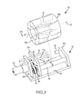
- FIG. 2-7 One embodiment of a horizontal mixer that may be used by the fluid system 10 of Figure 1 is illustrated in Figures 2-7 and is identified by reference numeral 50.
- the horizontal mixer 50 may be used for any appropriate application, including medical applications that utilize a slurry (e.g., for the production of radioisotopes).
- the horizontal mixer 50 includes a frame 52 that supports a tumbler, container, or mixer body 80, which in turn may be rotated relative to the frame 52 by a drive source 62 about an at least substantially horizontally disposed rotational axis 110.
- the frame 52 includes a bed 54. Multiple supports 56a-c extend from the bed 54 and may be integrated with the bed 54 in any appropriate manner.
- the drive source 62 may be supported by and mounted to the support 56a in any appropriate manner.
- the tumbler 80 may be located between the supports 56b, 56c. Further in this regard, a drive roller 58 extends between the supports 56b, 56c.
- one idler roller 60 is rotatably supported by the support 56b, and another axially aligned idler roller 60 is rotatably supported by the support 56c.
- the rollers 58, 60 engage and support an exterior surface 84b of the tumbler 80 (e.g., the rollers 58, 60 collectively define a cradle that supports the tumbler 80).
- the pair of idler rollers 60 could be replaced by a single idler roller that extends between the supports 56b, 56c (not shown).
- the single drive roller 58 could be replaced by a pair of drive rollers (not shown, but where one such drive roller is rotatably supported by the support 56b and where another such drive roller is rotatably supported by the support 56c, for instance in the manner of the idler rollers 60).
- the drive roller 58 is rotated by the drive source 62.
- a drive gear 64 is disposed between the supports 56a, 56b, and is rotatably driven by the output from the drive source 62.
- a driven gear 66 is also located between the supports 56a, 56b, and is interconnected with the drive gear 64 by a drive belt 68. Rotation of the drive gear 64 is thereby transmitted to the driven gear 66 by the drive belt 68.
- the driven gear 66 is appropriately interconnected with the drive roller 58. Rotation of the driven gear 66 thereby rotates the drive roller 58 (e.g., the driven gear 66 and the drive roller 58 rotate together and in the same direction).
- the driver roller 58 is engaged with an exterior surface 84b of the tumbler 80 (specifically, its sidewall 82 or an outer sidewall 84b). Rotation of the drive roller 58 rotates (e.g., drives) the tumbler 80 about its rotational axis 110.
- the idler rollers 60 also engage the exterior surface 84b of the tumbler 80 (specifically, its outer sidewall 82). In the illustrated embodiment, the idler rollers 60 are "free spinning", such that rotation of the tumbler 80 causes the idler rollers 60 to rotate. Any appropriate way of rotating the tumbler 80 may be utilized. Any appropriate way of rotatably supporting the tumbler 80 may be utilized as well.
- the tumbler 80 of the horizontal mixer 50 includes a tumbler or mixer sidewall 82 and a pair of tumbler or mixer ends 86a, 86b that are spaced along the rotational axis 110 and that collectively define a mixing chamber 90.
- One of the tumbler ends 86a (associated with the support 56b of the frame 52) includes an aperture or opening 88 through which an input/inlet line 70 and output/outlet line 72 may extend, and that will be discussed in more detail below.
- the tumbler end 86a could be disposed in sealing engagement with the support 56b (e.g., a seal that would allow the tumbler 80 to rotate relative to the support 56, and yet have a fluid-tight seal exist therebetween), or could be spaced therefrom.
- the tumbler end 86b is closed in the illustrated embodiment.
- the sidewall 82 may be of an at least generally cylindrical shape.
- An interior surface 84b of the sidewall 82 (or an inner sidewall 84b) includes a plurality of blades or fins 92.
- these blades 92 are orientated relative to the rotational axis 110 of the tumbler 80 or promote a desired mixing action within the mixing chamber 90 (e.g., providing a desired level of homogeneity of particles within the slurry).
- This mixing action may be characterized as slurry within the tumbler 80 being folded onto itself during rotation of the tumbler 80 and by the action of the various blades 92.
- This mixing action may also be characterized as the blades 92 funneling or directing a flow to a common region 78 within the mixing chamber 90 through at least a certain rotational angle, where slurry may be removed from this common region 78 through the above-noted output line 72 that extends therein.
- the mixing action may also be characterized as the blades 92 both lifting a portion of the slurry and inducing a pressure gradient within the lifted slurry portion that directs the same toward the common region 78, again where slurry may be removed from this common region 78 through the output line 72 that extends in this common region 78.
- the common region 78 is located at least generally mid-way between the ends 86a, 86b of the tumbler 80. Other locations may be appropriate.
- the tumbler 80 of the horizontal mixer 50 is shown in each of Figures 2 , 3 , and 4 . At least certain details regarding the blades 92 of the tumbler 80 are further shown in Figures 5A, 5B . Initially, it should be noted that the blades 92 extend from and rotate with the sidewall 82 of the tumbler 80 (specifically the interior surface 84a thereof). Any way of incorporating the blades 92 with the sidewall 82 of the tumbler 80 may be utilized (e.g., an integral or one-piece construction; having the blades 92 be separately attached or joined to the sidewall 82 and/or the corresponding tumbler end 86a, 86b in any appropriate manner).
- the blades 92 extend from the interior surface 84a of the sidewall 82 into the mixing chamber 90. This may be referred to as the "radial" direction or dimension. Although the blades 92 may extend orthogonally or perpendicularly from the interior surface 84a of the sidewall 82 (as shown in the illustrated embodiment), the blades 92 may extend from the interior surface 84a in other orientations.
- the blades 92 of the tumbler 80 also extend along the interior surface 84 of the sidewall 82. This may be referred to as a longitudinal or length dimension.
- Each blade 92 includes a pair of primary surfaces 98 that are oppositely disposed. In the illustrated embodiment, these primary surfaces are flat or planar, although other contours/shapes may be appropriate.
- the outlet region 78 is located in the longitudinal dimension between the first blades 92a and the second blades 92b.
- the plurality of first blades 92a may be characterized as being part of a first longitudinal segment of the tumbler 80
- the outlet region 78 may be characterized as being part of a second longitudinal segment of the tumbler 80
- the plurality of second blades 92b may be characterized as being part of a third longitudinal segment of the tumbler 80.
- these three longitudinal segments may be characterized as being disposed in non-overlapping relation. Another characterization may be that these three longitudinal segments are disposed in end-to-end relation and in the noted order, with the second longitudinal segment (including the outlet region 78) being located between the first longitudinal segment (including the first blades 92a) and the third longitudinal segment (including the second blades 92b) in the longitudinal dimension.
- the output line 72 extends into the above-noted outlet region 78, which may be characterized as an intermediate longitudinal segment of the tumbler 80.
- the output line 72 includes a first section 74a that extends at least primarily in the longitudinal dimension (e.g., at least generally parallel with the rotational axis 110), and a second section 74b that extends at least primarily in a downward direction.
- An end of the second section 74b includes an output/outlet port 76.
- the output port 76 is spaced from the interior surface 84a of the sidewall 82 for the tumbler 80. In one embodiment, the spacing between the output port 76 and the interior surface 84a is within a range of about 0.125 inches to about 0.135 inches.
- the output port 76 should be spaced a sufficient distance from the interior surface 84a of the sidewall 82 of the tumbler 80 so that the output port 76 does not become clogged. Spacing the output port 76 too far away from the interior surface 84a of the sidewall 82 of the tumbler 80 is also undesirable in that it will leave a large quantity of slurry within the tumbler 80.
- Each blade 92 includes a first blade end 94 and a second blade end 96.
- the length of a given blade 92 corresponds with the spacing between its first blade end 94 and its second blade end 96.
- the first blade end 94 may be located on or adjacent to the first tumbler end 86a and the second blade end 96 may be spaced from the first tumbler end 86a (e.g., each first blade 92a may be characterized as extending from the first tumbler end 86a at least generally in the direction of the second tumbler end 86b, but terminating prior to reaching the second tumbler end 86b).
- the second blade end 96 of each first blade 92a may be located between the second tumbler end 86b and its corresponding first blade end 94 in the longitudinal dimension.
- the first blade end 94 may be located on or adjacent to the second tumbler end 86b and the second blade end 96 may be spaced from the second tumbler end 86b (e.g., each second blade 92b may be characterized as extending from the second tumbler end 86b at least generally in the direction of the first tumbler end 86a, but terminating prior to reaching the first tumbler end 86a). Stated another way, the second blade end 96 of each second blade 92b may be located between the first tumbler end 86a and its corresponding first blade end 94 in the longitudinal dimension.
- Each of the blades 92 may be characterized as being "center angled.” Center angling of the various blades 92 may promote a desired mixing action within the mixing chamber 90 of the horizontal mixer 50. A number of characterizations may be made in relation to the orientation of each blade 92 relative to the rotational axis 110 of the tumbler 80, which may apply individually or in any combination. Consider the case where a plurality of reference axes 112 are on the sidewall 82 of the tumbler 80 and are parallel to the rotational axis 110 of the tumbler 80.
- the first blade end 94 may be on one such reference axis 112 and its corresponding second blade end 96 may be on a different reference axis (e.g., Figure 6 ) for each of the various blades 92, and which may be used to promote a desired mixing action in the mixing chamber 90 of the tumbler 80.
- Each blade 92 may be of the same height, where "height" is the distance that the blades 92 extend away from where the blades 92 intersect with the interior surface 84a of the tumbler 80.
- the height of each blade 92 may be constant along the entire length thereof.
- the first blade end 94 of each blade 92 at its intersection with the interior surface 84a of the tumbler 80 is at a different elevation than its corresponding second blade end 94 at its intersection with the interior surface 84a, where the elevation is measured relative to a horizontal reference plane located below the tumbler 80.
- the elevation continually changes at the intersection between each blade 92 and the interior surface 84a of the tumbler 80 proceeding from its first blade end 94 to its corresponding second blade end 96, again where the elevation is measured relative to a horizontal reference plane located below the tumbler 80.
- the first blade end 94 leads its corresponding second blade end 96 in a first rotational direction in the case of each blade 92, and which may be used to promote a desired mixing action in the mixing chamber 90 of the tumbler 80.
- the first rotational direction is counterclockwise.
- the arrow about the rotational axis 110 indicates the first rotational direction in each of Figures 2 , 5A , 5B , and 7 (again, counterclockwise).
- the second blade end 96 may lag its corresponding first blade end 94 in a first rotational direction in the case of each blade 92.
- Figure 7 further illustrates the above-noted leading/lagging relationship, with the arrow about the rotational axis 110 being the first rotational direction.
- the first blade end 94 of each first blade 92a is shown in dashed lines, as is an edge corresponding with each corresponding second blade end 96.
- the first blade end 94 of each first blade 92a will reach and pass the 6 o'clock position (such a "clock" being measured about the rotational axis 110) before its corresponding second blade end 96 reaches and passes the 6 o'clock position.
- the various blades 92 for the mixer 50 are arranged so that there is a plurality of blade pairs 100 that are spaced about the rotational axis 110 (e.g., each blade pair being located at a different angular position relative to and measured about the rotational axis 110). Any number of blade pairs 100 may be utilized (6 blade pairs 100 in the illustrated embodiment). The blade pairs 100 are equally spaced about the rotational axis 100 in the illustrated embodiment, although other spacing arrangements could be utilized.
- Each blade pair 100 includes one first blade 92a and one second blade 92b.
- the first blade 92a and its corresponding second blade 92b (one first blade 92a and its corresponding second blade 92b defining a blade pair 100) are disposed in a mirror image relationship to each other.
- each included angle 114a is the same for all first blades 92a
- the magnitude of each included angle 114b is the same for all second blades 92b
- the magnitudes of the included angles 114a and 114b are the same. This allows for the above-noted mirror image relationship.
- each included angle 114a, 114b is within a range of about 3° to about 4°. The incline of the various blades 92a, 92b allows the output line 72, more specifically its output port 76, to be disposed in a "deeper reservoir" of slurry within the tumbler 80.
- the various blade pairs 100 have an at least generally V-shaped profile.
- the second blade ends 96 of each blade pair 100 are separated by a gap 102 that coincides with the region 78 into which the output line 72 extends for withdrawing slurry from the mixer 50.
- the "V" of each blade pair 100 is oriented such that the noted gap 102 is the trailing portion of each blade pair 100 in the above-noted first rotational direction that is used for promoting a desired mixing action within the mixing chamber 90 during rotation of the tumbler 80 about its rotational axis 110 in the first rotational direction.
- each blade pair 100 are orientated so each blade pair 100 is in the form of a concave structure in the first rotational direction (e.g., each blade pair 100 collectively defines an at least generally concave profile relative to the first rotational direction).
- the magnitude of the included angle 114a of each first blade 92a may be the same, the magnitude of the included angle 114b of each second blade 92b may be the same, but the magnitudes of the included angles 114a and included angles 114b may be different.
- the included angle 114a of the various first blades 92a e.g., one or more first blades 92a may be disposed at one common included angle 114a, while one or more other first blades 92a may be disposed at another common included angle 114a
- one or more different magnitudes are utilized for the included angle 114b of the various second blades 92b (e.g., one or more second blades 92b may be disposed at one common included angle 114b, while one or more other second blades 92b may be disposed at another common included angle 114b), or both.
- first blades 92a may be disposed about the rotational axis 110 in one pattern
- the second blades 92b may be disposed about the rotational axis 110 in a different pattern.
- the first blades 92a and second blades 92b may be disposed in staggered relation about the rotational axis 110. For instance, when the first blade end 94 of the first blades 92a are at the 2, 4, 6, 8, 10, and 12 o'clock positions in a first static position for the tumbler 80, the first blade end 94 of the second blades 92b may be at the 1, 3, 5, 7, 9, and 11 o'clock positions.
- the horizontal mixer 50 may be used in the fluid system 10 (in place of the horizontal mixer 20) to provide a slurry from which radioisotopes are produced.
- Figure 8 illustrates onef such production method 120.
- the radioisotope production method 120 includes mixing a slurry from which radioisotopes may be produced (step 122).
- the horizontal mixer 50 may be used to mix such a slurry, including when incorporated into the fluid system 10.
- the slurry may include particles of alumina. Other particles that may be used by such a slurry include without limitation other chromatographic media for bonding or stripping. Other liquids that may be used for such a slurry include without limitation distilled water or media preparation solvents.
- the slurry may be dispensed into an appropriate container (e.g., a glass column) pursuant to step 124 of the production method 120. This may entail using an appropriate dispensing apparatus, or it may be done by hand.
- the column may be loaded with a chemical or compound that adsorbs to the adsorbant materials that were part of the slurry (Step 126).
- the column may be utilized in a technetium generator wherein molybdenium-99 is added to the column, adsorbing onto the alumina column packing material. Over time, the molybdenium-99 decays to technetium-99m, a daughter radioisotope that is used in many nuclear medicine procedures (Step 128).
Landscapes
- Chemical & Material Sciences (AREA)
- Chemical Kinetics & Catalysis (AREA)
- Dispersion Chemistry (AREA)
- Mixers Of The Rotary Stirring Type (AREA)
Description
- The present invention generally relates to the field of mixers and, more particularly, to how blades may be incorporated by a mixer to enhance mixing.
- Various types of mixers exist and for a variety applications. One type of mixer uses a vertically-oriented shaft with blades attached thereto, and which is disposed in an appropriate housing. The shaft and blades rotate relative to the housing. In the case where these types of mixers are used for producing abrasive slurries from which radioisotopes are formed, the abrasive particles tend to chip the blades such that these blade chips become part of the abrasive slurry. Moreover, centrifugal forces create a distribution of particles within the slurry - particles are distributed in the slurry based upon their respective weights progressing away from the rotating shaft (i.e., heavier particles will be directed further away from the vertically oriented, rotating shaft than lighter particles). Although this may be acceptable for certain applications, other applications could benefit for a more homogenous distribution of particles within the slurry.
- For example,
US2009/0073798 describes a batch mixer comprising a mixing drum rotatable about a longitudinal axis extending between an inlet opening and a discharge opening at opposing ends of the drum. - In addition,
US1,093,723 describes a rotary mixing machine according to the preamble of claim 1 comprising a revolvable mixing drum provided with a plurality of mixing blades or battles arranged to deliver materials to a discharge chute at one side of the drum. - A first aspect of the present invention is embodied by a horizontal mixer for producing a slurry from which isotopes may be produced. This mixer includes a container or tumbler that is able to rotate about an at least substantially horizontally disposed rotational axis, an inner sidewall that is disposed about this rotational axis (e.g., extends a full 360° about this rotational axis), and a mixing chamber that is at least partially defined by this inner sidewall. Multiple blades or fins extend from the inner sidewall of the container and in the direction of an interior of the mixing chamber (e.g., defining protrusions on the inner sidewall). These blades are oriented to direct fluid toward an outlet from the mixing chamber for at least a certain rotational angle and during rotation of the container in a first rotational direction about its rotational axis.
- This mixer includes a container or tumbler having first and second container/tumbler ends that are spaced along an at least substantially horizontally disposed rotational axis of the container. The inner sidewall of the container is disposed about its rotational axis and may extend between the first and second container ends. The first and second container ends, along with the inner sidewall, may at least partially define a mixing chamber for the container. The outlet may accommodate a discharge from the mixing chamber.
- A plurality of first blades or fins and a plurality of second blades or fins each extend from the inner sidewall of the container and in the direction of an interior of the mixing chamber (e.g., defining protrusions on the inner sidewall). Each of the first and second blades has a first blade end and a second blade end. Each first blade extends from its corresponding first blade end toward its corresponding second blade end at least generally in the direction of the second container end (e.g., the second blade end of each first blade may be characterized as being between its corresponding first blade end and the second container end relative to a dimension in which the rotational axis of the container extends (hereafter a "longitudinal dimension)). Each second blade extends from its corresponding first blade end toward its corresponding second blade end at least generally in the direction of the first container end (e.g., the second blade end of each second blade may be characterized as being between its corresponding first blade end and the first container end relative to the longitudinal dimension). The first blade end of each first and second blade leads its corresponding second blade end in a first rotational direction for the container.
- The first container end comprises an aperture, and the horizontal mixer further comprises an outlet conduit that extends through the aperture and to a location in a longitudinal dimension that is between the second ends of the plurality of first blades and the second ends of the plurality of second blades. The longitudinal dimension coincides with the rotational axis.
- A number of feature refinements and additional features are separately applicable to the present invention. These feature refinements and additional features may be used individually or in any combination. As such, each of the following features that will be discussed may be, but are not required to be, used with any other feature or combination of features of the invention. Each blade used by the horizontal mixer may be of any appropriate size, shape, configuration, and/or type. For instance, each blade may be in the form of a plate having a pair of oppositely disposed flat or planar surfaces. Although each blade may be of an identical configuration and size, such may not be the case in all instances. Any appropriate number of blades may be utilized by the horizontal mixer, and the blades may be integrated with the container in any appropriate manner (e.g., by being separately attached to the inner sidewall of the container; by being integrally formed with the container such that there is no joint of any kind between the inner sidewall of the container and each of its blades).
- The blades may be arranged on the inner sidewall of the container to promote a desired mixing action of contents within the mixing chamber of the horizontal mixer. The blades may extend along the inner sidewall of the container in non-parallel relation to the rotational axis of the horizontal mixer. The blades may be oriented so as to be "center angled." One embodiment has the length dimension of each blade (the length dimension of a blade coinciding with the direction that the blade extends along the inner sidewall of the container) proceeding in a direction so as to direct fluid toward the outlet from the mixing chamber throughout at least a certain rotational angle of the container proceeding in the first rotational direction. Each blade may be oriented relative to the inner sidewall so as to bias a fluid flow toward the outlet throughout at least a certain rotational angle of the container proceeding in the first rotational direction.
- The blade orientation may be described in relation to the location of its two blade ends - the spacing between which corresponds with the length dimension of the blade. The two blade ends of each blade, at its intersection with the inner sidewall of the container may be disposed at different elevations relative to a horizontal reference plane that is disposed below the horizontal mixer. Although the elevation of this intersection could continually change between these two blades ends in this instance, such may not always be the case.
- The two ends of each blade may be disposed on different reference axes that are each parallel to the rotational axis of the tumbler. Consider the case where each blade has a first blade end and an oppositely disposed second blade end. The first blade end of a given blade may be disposed on a first reference axis and the second blade end may be disposed on a different second reference axis, where each of the first and second reference axes are parallel to the rotational axis of the horizontal mixer. Stated another way, the first and second blade ends of each blade may be characterized as being located at different angular positions, measured relative to the rotational axis of the tumbler.
- The end of each blade that is adjacent-most to an end of the horizontal mixer may lead its opposite end in a first rotational direction for the container. Consider the case where a first blade end of a blade is disposed between a first container end of the horizontal mixer and its oppositely disposed second blade end proceeding in the longitudinal dimension. During rotation of the container in a first rotational direction, the first blade end of the noted blade will pass the 6 o'clock position before its second blade end passes this same 6 o'clock position when the first blade end leads the second blade end in the first rotational direction. The second blade end could also be characterized as lagging its corresponding first blade end during rotation of the container in this same first rotational direction.
- The invention utilizes both a plurality of first blades and a plurality of second blades, where each of the first and second blades has a first blade end and a second blade end, where each first blade extends from its corresponding first blade end toward its corresponding second blade end at least generally in the direction of a second container end of the container for the horizontal mixer (e.g., the second blade end of each first blade may be characterized as being between its corresponding first blade end and the second container end relative to or proceeding along the rotational axis of the container), where each second blade extends from its corresponding first blade end toward its corresponding second blade end at least generally in the direction of a first container end of the container for the horizontal mixer (e.g., the second blade end of each second blade may be characterized as being between its corresponding first blade end and the first container end relative to or proceeding along the rotational axis of the container), and where the first blade end of each first and second blade leads its corresponding second blade end in a first rotational direction for the container. The first blade end of each first blade may be located at or at least generally proximate to the first container end, while the first blade end of each second blade may be located at or at least generally proximate to the second container end (where the first and second container ends again are spaced along the rotational axis of the horizontal mixer). The horizontal mixer may be characterized as including a plurality of blade pairs, where each blade pair includes one first blade and one second blade. The first and second blades of each blade pair may be oriented as the mirror image of each other. Each blade pair may define at least generally V-shaped configuration. Each blade pair may collectively define a concave profile relative to the first rotational direction. A space between the blades of each blade pair may define the trailing portion of the blade pair when the container is rotated about its rotational axis in the first rotational direction.
- The position of the plurality of second blades could be staggered in relation to the position of the plurality of first blades. The first blade end of each first blade could be disposed at a different angular position (relative to the rotational axis of the container) than the first blade end of each second blade. Consider the case where there are 6 first blades and 6 second blades. The first blade ends of the 6 first blades could be disposed at the 1, 3, 5, 7, 9, and 11 o'clock positions in a first static position for the container, while the first ends of the 6 second blades could be disposed at the 2, 4, 6, 8, 10, and 12 o'clock positions in this same first static position, or vice versa.
- The length dimension of the various first and second blades may be disposed at a common angle relative to a reference axis that intersects their corresponding second blade end and that is parallel to the rotational axis of the horizontal mixer. Stated another way, the same angle may be defined between the length of each blade and a reference axis that intersects its second blade end and that is parallel to the rotational axis. Another option would be for the length dimension of the plurality of first blades to be disposed at a common first angle relative to a reference axis that intersects their corresponding second blade end and that is parallel to the rotational axis of the horizontal mixer, for the length dimension of the plurality of second blades to be disposed at a common second angle relative to a reference axis that intersects their corresponding second blade end and that is parallel to the rotational axis of the horizontal mixer, and for the magnitudes of the first and second angles to be different.
- The plurality of first blades may coincide with or define a first longitudinal segment of the horizontal mixer, the plurality of second blades may coincide with or define a third longitudinal segment of the horizontal mixer, and a second longitudinal segment of the horizontal mixer may be located between the first and third longitudinal segments. The longitudinal dimension may coincide with the rotational axis of the horizontal mixer. In any case, the second longitudinal segment may include the outlet. One embodiment has the first, second, and third longitudinal segments being disposed in non-overlapping relation. Another embodiment has the first, second, and third longitudinal segments being disposed in end-to-and relation and in the noted order.
- The outlet from the mixing chamber may be located between the second ends of the various first blades and the second ends of the various second blades. The second ends of the various first blades may be spaced from the second ends of the various second blades in a direction coinciding with the rotational axis of the horizontal mixer, and the outlet from the mixing chamber may be located within this space. In one embodiment, the outlet from the mixing chamber may be at least substantially mid-way between the first and second container ends of the horizontal mixer.
- The first container end includes an aperture, and the horizontal mixer further includes an outlet conduit that extends through this aperture and into the mixing chamber. The aperture may be significantly larger than the outer diameter of the portion of the outlet conduit that passes therethrough. A first outlet conduit section may extend through this aperture and at least generally in the direction of the oppositely disposed second container end (e.g., at least generally parallel with the rotational axis of the horizontal mixer), and a second outlet conduit section may extend from the first outlet conduit section in at least a generally downward direction and may terminate prior to reaching the inner sidewall of the container to define the outlet from the mixing chamber. This second outlet conduit section may be disposed within the space between the second blade ends of the various first blades and the second blade ends of the various second blades. Other outlet configurations may be appropriate. It should be noted that the fluid level within the mixing chamber may be controlled such fluid does not spill out of the noted aperture in the first container end (e.g., the fluid level may be below the rotational axis of the container, including significantly below).
- A second aspect of the present invention is directed to a fluid system that utilizes a horizontal mixer according to the first aspect, at least one feed source fluidly connected with the horizontal mixer, and a slurry target fluidly connected with the outlet of the horizontal mixer. Fluid and a plurality of particles are directed into the horizontal mixer by the at least one feed source, and a discharge from the outlet of the horizontal mixer comprises a slurry that is directed to the slurry target.
- A number of feature refinements and additional features are applicable to the second aspect of the present invention. These feature refinements and additional features may be used individually or in any combination. As such, each of the following features that will be discussed may be, but are not required to be, used with any other feature or combination of features of the second aspect. Any of the features of the horizontal mixer discussed above in relation to the first aspect may be utilized by the horizontal mixer that is utilized by this second aspect, individually or in any combination.
- The fluid system may utilize two or more separate feed sources. One feed source may contain a supply of particles, while another feed source may contain a supply of an appropriate fluid (e.g., one or more appropriate liquids). Each feed source could provide a direct flow or a separate stream to the horizontal mixer. Alternatively, the output from two or more feed sources could be combined before actually being directed into the horizontal mixer (e.g., into a common inlet manifold or header). A given feed source could contain both particles and fluid for a slurry.
- Any appropriate type of particulates may be introduced into the horizontal mixer and in any appropriate manner. In one embodiment, aluminum oxide (alumina) is directed into the horizontal mixer, and alumina slurry is removed from the horizontal mixer and is ultimately directed into a glass column, vial, container, or the like for use in the process of column chromatography. Solvents and other chemicals may be added to the column of alumina to initiate a chemical process that produces radioisotopes. The resulting radioisotopes may be used for any appropriate application, such as for medical diagnosis, medical treatment, or medical research. As such, the fluid system of the second aspect may be characterized as one that provides slurry from which isotopes may be produced, including radioisotopes. If the column of alumina contains particles that are unevenly distributed, the chemical process that produces the radioisotope may be skewed. The horizontal mixer described in relation to the first aspect may provide a desired degree of homogeneity for slurry from which isotopes may be produced.
- The slurry target may be of any appropriate type. One embodiment has the slurry target in the form of a dispenser that is used to provide slurry to an end-use container (e.g., a glass column, vial, or other container). Another embodiment has the slurry target being in the form of an end-use container. Although the slurry may be of any appropriate type and used for any appropriate application, in one embodiment the slurry contains abrasive particulate matter for nuclear medicine applications.
- The horizontal mixer may be used to provide a slurry. A plurality of particles and fluid may be directed into the mixer. The mixer may be rotated about the first axis. A first flow may be directed from the first mixer end toward a first location within the mixer that is located between the first and second mixer ends. Similarly, a second flow may be directed from the second mixer and toward this same first location. The slurry may be withdrawn from the first location of the mixer, and may include a distribution of the particles in the fluid.
- A first stream of particles may be directed into the mixer. A separate, second stream of fluid may be directed into the mixer. Another option is for a first stream of particles and a second stream of fluid to be combined before being introduced into the mixer. A single stream of particles and fluid could be directed into the mixer as well. The particles may be in the form of alumina.
- Fluid may be directed to the first location using gravitational forces. For instance, the orientation of the blades discussed above in relation to the first, second, and third aspects may be used to induce a gravitational flow along the blades in the direction of the first location through at least a certain rotational angle of the mixer. The induced flow toward the first location within the mixer may be the result of exerting a lifting force on a portion of the contents within the mixer and simultaneously inducing a pressure gradient on this portion of the contents. For instance, a blade on an inner sidewall of the mixer may be rotated into the fluid, and during continued rotation may exert both a lifting force on a portion of the fluid (and any particles therein) and may direct this fluid portion toward the first location.
- Slurry may be withdrawn from the horizontal mixture (e.g., via pump, such as a peristaltic pump) and provided to a dispenser of any appropriate type. Slurry provided to the dispenser may be directed to multiple locations. One is a container (e.g., a glass column, vial, or the like). Another is a recirculation loop back to the horizontal mixer. Slurry may enter the dispenser and may be provided to a container. At least part of the slurry that may be directed into the dispenser may be recirculated back to the horizontal mixer. Slurry that may be delivered to a container may be used to produce isotopes, including radioisotopes.
- A number of feature refinements and additional features are separately applicable to each of above-noted first and second aspects of the present invention. These feature refinements and additional features may be used individually or in any combination in relation to each of the above-noted first and second aspects. Any feature of the various aspects of the present invention that is intended to be limited to a "singular" context or the like will be clearly set forth herein by terms such as "only," "single," "limited to," or the like. Merely introducing a feature in accordance with commonly accepted antecedent basis practice does not limit the corresponding feature to the singular (e.g., indicating that a fluid system includes "a pump" alone does not mean that the fluid system includes only a single pump). Moreover, any failure to use phrases such as "at least one" also does not limit the corresponding feature to the singular (e.g., indicating that a fluid system includes "a pump" alone does not mean that the fluid system includes only a single pump). Use of the phrase "at least generally" or the like in relation to a particular feature encompasses the corresponding characteristic and insubstantial variations thereof (e.g., indicating that a mixer rotates about an axis that is at least generally horizontally disposed encompasses the mixer rotating about a horizontal axis). Finally, a reference of a feature in conjunction with the phrase "in one embodiment" does not limit the use of the feature to a single embodiment.
-
-
Figure 1 is a schematic of a fluid system that utilizes a horizontal mixer. -
Figure 2 is a perspective view of one embodiment of a horizontal mixer that may be used by the fluid system ofFigure 1 , with the tumbler being exploded away from the frame, and with its various blades being shown in their entirety for clarity. -
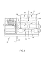
Figure 3 is a side view of the horizontal mixer ofFigure 2 , and with its various blades being shown in their entirety for clarity. -
Figure 4 is a perspective view of the tumbler from the horizontal mixer ofFigure 2 , and with its various blades being shown in their entirety for clarity. -
Figure 5A is a perspective view of the interior of the tumbler ofFigure 4 and showing one of the blade pairs in about the 8 o'clock position. -
Figure 5B is a perspective view of the interior of the tumbler ofFigure 4 and showing one of the blade pairs in about the 4 o'clock position. -
Figure 6 is a plan view of part of the interior of the tumbler ofFigure 4 , illustrating the orientation of one of its blade pairs. -
Figure 7 is an end view of the tumbler ofFigure 4 , illustrating the angular position and orientation of its plurality of first blades. -
Figure 8 is a schematic of one embodiment for producing radioisotopes. -
Figure 1 is a schematic representation of one embodiment of afluid system 10 that may be used to provide a slurry to a desired slurry target. As such, thefluid system 10 could also be referred to as aslurry system 10. Thefluid system 10 utilizes as least one feed source to direct slurry components into ahorizontal mixer 20. In the illustrated embodiment, afirst feed source 12 is fluidly connected with thehorizontal mixer 20 and contains a first slurry component (e.g., particles or particulates). Asecond feed source 14 is also fluidly connected with thehorizontal mixer 20 and contains a second slurry component (e.g., a fluid). A single feed source could be used to provide the slurry components to thehorizontal mixer 20. Three or more feed sources could also be used to provide different slurry components to thehorizontal mixer 20. - One or more feed sources are in a direct fluid connection with the
horizontal mixer 20, two or more feed sources could have their outputs merged or combined prior to entering thehorizontal mixer 20, or any combination thereof. A separate input orinlet line 16 may extend between thehorizontal mixer 20 and each of thefirst feed source 12 and the second feed source 14 (indicated by the solid lines inFigure 1 ). The output from thefirst feed source 12 andsecond feed source 14 alternatively may be directed into a common input or inlet line 18 (where their respective outputs are merged or combined, and indicated by the dashed line inFigure 1 ) that extends to thehorizontal mixer 20. Thecommon input line 18 may include a common header or intake manifold that receives a flow, output, or discharge from each of thefirst feed source 12 andsecond feed source 14, and directs or introduces the same into thehorizontal mixer 20 in the form of a single input or stream. - The
mixer 20 used by thefluid system 10 is of the horizontal type - a mixer that rotates about an at least substantially horizontally disposed rotational axis. Thehorizontal mixer 20 is rotatably driven by adrive source 22. The output from thedrive source 22 rotates adrive shaft 24, which in turn is appropriately interconnected with thehorizontal mixer 20 to rotate the same. Thedrive source 22 may be of any appropriate size, shape, configuration, and/or type. Multiple drive sources could also be used to rotate thehorizontal mixer 20. - Slurry from the
horizontal mixer 20 may be withdrawn through an output oroutline line 26. Apump 28 of any appropriate type (e.g., peristaltic) may be used to withdraw slurry from thehorizontal mixer 20, to transfer the slurry to a desired slurry target, or both. In the illustrated embodiment, slurry from thehorizontal mixer 20 is directed into adispenser 30 via theoutput line 26. Thedispenser 30 may be of any appropriate size, shape, configuration, and/or type. There are two available flowpaths out of thedispenser 30. Thedispenser 30 may direct slurry into a container 36 (e.g., a column, vial, or the like) via an output oroutlet line 32. Thedispenser 30 may also direct slurry back to thehorizontal mixer 20 via arecirculation line 34. Thedispenser 30 may be configured to direct a certain quantity of slurry into thecontainer 36, while the remainder of the slurry being directed into thedispenser 30 may be recirculated back to thehorizontal mixer 20 by therecirculation line 34. It should be appreciated that one or more valves, controllers, or the like (not shown) may be utilized by thefluid system 10 to control one or more aspects of its operation. - One embodiment of a horizontal mixer that may be used by the
fluid system 10 ofFigure 1 is illustrated inFigures 2-7 and is identified byreference numeral 50. Thehorizontal mixer 50 may be used for any appropriate application, including medical applications that utilize a slurry (e.g., for the production of radioisotopes). - The
horizontal mixer 50 includes aframe 52 that supports a tumbler, container, ormixer body 80, which in turn may be rotated relative to theframe 52 by adrive source 62 about an at least substantially horizontally disposedrotational axis 110. Theframe 52 includes abed 54. Multiple supports 56a-c extend from thebed 54 and may be integrated with thebed 54 in any appropriate manner. Thedrive source 62 may be supported by and mounted to thesupport 56a in any appropriate manner. Thetumbler 80 may be located between thesupports drive roller 58 extends between thesupports idler roller 60 is rotatably supported by thesupport 56b, and another axially alignedidler roller 60 is rotatably supported by thesupport 56c. Therollers exterior surface 84b of the tumbler 80 (e.g., therollers idler rollers 60 could be replaced by a single idler roller that extends between thesupports single drive roller 58 could be replaced by a pair of drive rollers (not shown, but where one such drive roller is rotatably supported by thesupport 56b and where another such drive roller is rotatably supported by thesupport 56c, for instance in the manner of the idler rollers 60). - In the illustrated embodiment, the
drive roller 58 is rotated by thedrive source 62. In this regard, a drive gear 64 is disposed between thesupports drive source 62. A drivengear 66 is also located between thesupports gear 66 by the drive belt 68. The drivengear 66 is appropriately interconnected with thedrive roller 58. Rotation of the drivengear 66 thereby rotates the drive roller 58 (e.g., the drivengear 66 and thedrive roller 58 rotate together and in the same direction). - The
driver roller 58 is engaged with anexterior surface 84b of the tumbler 80 (specifically, itssidewall 82 or anouter sidewall 84b). Rotation of thedrive roller 58 rotates (e.g., drives) thetumbler 80 about itsrotational axis 110. Theidler rollers 60 also engage theexterior surface 84b of the tumbler 80 (specifically, its outer sidewall 82). In the illustrated embodiment, theidler rollers 60 are "free spinning", such that rotation of thetumbler 80 causes theidler rollers 60 to rotate. Any appropriate way of rotating thetumbler 80 may be utilized. Any appropriate way of rotatably supporting thetumbler 80 may be utilized as well. - The
tumbler 80 of thehorizontal mixer 50 includes a tumbler ormixer sidewall 82 and a pair of tumbler or mixer ends 86a, 86b that are spaced along therotational axis 110 and that collectively define a mixingchamber 90. One of the tumbler ends 86a (associated with thesupport 56b of the frame 52) includes an aperture oropening 88 through which an input/inlet line 70 and output/outlet line 72 may extend, and that will be discussed in more detail below. Thetumbler end 86a could be disposed in sealing engagement with thesupport 56b (e.g., a seal that would allow thetumbler 80 to rotate relative to the support 56, and yet have a fluid-tight seal exist therebetween), or could be spaced therefrom. Thetumbler end 86b is closed in the illustrated embodiment. Thesidewall 82 may be of an at least generally cylindrical shape. - An
interior surface 84b of the sidewall 82 (or aninner sidewall 84b) includes a plurality of blades orfins 92. Generally, theseblades 92 are orientated relative to therotational axis 110 of thetumbler 80 or promote a desired mixing action within the mixing chamber 90 (e.g., providing a desired level of homogeneity of particles within the slurry). This mixing action may be characterized as slurry within thetumbler 80 being folded onto itself during rotation of thetumbler 80 and by the action of thevarious blades 92. This mixing action may also be characterized as theblades 92 funneling or directing a flow to acommon region 78 within the mixingchamber 90 through at least a certain rotational angle, where slurry may be removed from thiscommon region 78 through the above-notedoutput line 72 that extends therein. The mixing action may also be characterized as theblades 92 both lifting a portion of the slurry and inducing a pressure gradient within the lifted slurry portion that directs the same toward thecommon region 78, again where slurry may be removed from thiscommon region 78 through theoutput line 72 that extends in thiscommon region 78. In one embodiment, thecommon region 78 is located at least generally mid-way between theends tumbler 80. Other locations may be appropriate. - The
tumbler 80 of thehorizontal mixer 50 is shown in each ofFigures 2 ,3 , and4 . At least certain details regarding theblades 92 of thetumbler 80 are further shown inFigures 5A, 5B . Initially, it should be noted that theblades 92 extend from and rotate with thesidewall 82 of the tumbler 80 (specifically theinterior surface 84a thereof). Any way of incorporating theblades 92 with thesidewall 82 of thetumbler 80 may be utilized (e.g., an integral or one-piece construction; having theblades 92 be separately attached or joined to thesidewall 82 and/or the correspondingtumbler end blades 92 extend from theinterior surface 84a of thesidewall 82 into the mixingchamber 90. This may be referred to as the "radial" direction or dimension. Although theblades 92 may extend orthogonally or perpendicularly from theinterior surface 84a of the sidewall 82 (as shown in the illustrated embodiment), theblades 92 may extend from theinterior surface 84a in other orientations. - The
blades 92 of thetumbler 80 also extend along the interior surface 84 of thesidewall 82. This may be referred to as a longitudinal or length dimension. Eachblade 92 includes a pair ofprimary surfaces 98 that are oppositely disposed. In the illustrated embodiment, these primary surfaces are flat or planar, although other contours/shapes may be appropriate. - There are basically two groups of
blades 92 for the tumbler 80 - a plurality offirst blades 92a that extend at least generally from thefirst tumbler end 86a, and a plurality ofsecond blades 92b that extend at least generally from thesecond tumbler end 86b. Theoutlet region 78 is located in the longitudinal dimension between thefirst blades 92a and thesecond blades 92b. As such, the plurality offirst blades 92a may be characterized as being part of a first longitudinal segment of thetumbler 80, theoutlet region 78 may be characterized as being part of a second longitudinal segment of thetumbler 80, and the plurality ofsecond blades 92b may be characterized as being part of a third longitudinal segment of thetumbler 80. In the illustrated embodiment, these three longitudinal segments may be characterized as being disposed in non-overlapping relation. Another characterization may be that these three longitudinal segments are disposed in end-to-end relation and in the noted order, with the second longitudinal segment (including the outlet region 78) being located between the first longitudinal segment (including thefirst blades 92a) and the third longitudinal segment (including thesecond blades 92b) in the longitudinal dimension. - The
output line 72 extends into the above-notedoutlet region 78, which may be characterized as an intermediate longitudinal segment of thetumbler 80. In the illustrated embodiment, theoutput line 72 includes afirst section 74a that extends at least primarily in the longitudinal dimension (e.g., at least generally parallel with the rotational axis 110), and asecond section 74b that extends at least primarily in a downward direction. An end of thesecond section 74b includes an output/outlet port 76. Theoutput port 76 is spaced from theinterior surface 84a of thesidewall 82 for thetumbler 80. In one embodiment, the spacing between theoutput port 76 and theinterior surface 84a is within a range of about 0.125 inches to about 0.135 inches. Generally, theoutput port 76 should be spaced a sufficient distance from theinterior surface 84a of thesidewall 82 of thetumbler 80 so that theoutput port 76 does not become clogged. Spacing theoutput port 76 too far away from theinterior surface 84a of thesidewall 82 of thetumbler 80 is also undesirable in that it will leave a large quantity of slurry within thetumbler 80. - Each
blade 92 includes afirst blade end 94 and asecond blade end 96. The length of a givenblade 92 corresponds with the spacing between itsfirst blade end 94 and itssecond blade end 96. In the case of thefirst blades 92a, thefirst blade end 94 may be located on or adjacent to thefirst tumbler end 86a and thesecond blade end 96 may be spaced from thefirst tumbler end 86a (e.g., eachfirst blade 92a may be characterized as extending from thefirst tumbler end 86a at least generally in the direction of thesecond tumbler end 86b, but terminating prior to reaching thesecond tumbler end 86b). Stated another way, thesecond blade end 96 of eachfirst blade 92a may be located between thesecond tumbler end 86b and its correspondingfirst blade end 94 in the longitudinal dimension. - In the case of the
second blades 92b, thefirst blade end 94 may be located on or adjacent to thesecond tumbler end 86b and thesecond blade end 96 may be spaced from thesecond tumbler end 86b (e.g., eachsecond blade 92b may be characterized as extending from thesecond tumbler end 86b at least generally in the direction of thefirst tumbler end 86a, but terminating prior to reaching thefirst tumbler end 86a). Stated another way, thesecond blade end 96 of eachsecond blade 92b may be located between thefirst tumbler end 86a and its correspondingfirst blade end 94 in the longitudinal dimension. - Each of the
blades 92 may be characterized as being "center angled." Center angling of thevarious blades 92 may promote a desired mixing action within the mixingchamber 90 of thehorizontal mixer 50. A number of characterizations may be made in relation to the orientation of eachblade 92 relative to therotational axis 110 of thetumbler 80, which may apply individually or in any combination. Consider the case where a plurality ofreference axes 112 are on thesidewall 82 of thetumbler 80 and are parallel to therotational axis 110 of thetumbler 80. Thefirst blade end 94 may be on onesuch reference axis 112 and its correspondingsecond blade end 96 may be on a different reference axis (e.g.,Figure 6 ) for each of thevarious blades 92, and which may be used to promote a desired mixing action in the mixingchamber 90 of thetumbler 80. - Each
blade 92 may be of the same height, where "height" is the distance that theblades 92 extend away from where theblades 92 intersect with theinterior surface 84a of thetumbler 80. The height of eachblade 92 may be constant along the entire length thereof. In one embodiment, thefirst blade end 94 of eachblade 92 at its intersection with theinterior surface 84a of thetumbler 80 is at a different elevation than its correspondingsecond blade end 94 at its intersection with theinterior surface 84a, where the elevation is measured relative to a horizontal reference plane located below thetumbler 80. In one embodiment, the elevation continually changes at the intersection between eachblade 92 and theinterior surface 84a of thetumbler 80 proceeding from itsfirst blade end 94 to its correspondingsecond blade end 96, again where the elevation is measured relative to a horizontal reference plane located below thetumbler 80. - The
first blade end 94 leads its correspondingsecond blade end 96 in a first rotational direction in the case of eachblade 92, and which may be used to promote a desired mixing action in the mixingchamber 90 of thetumbler 80. In the view shown inFigures 5A and 5B , the first rotational direction is counterclockwise. The arrow about therotational axis 110 indicates the first rotational direction in each ofFigures 2 ,5A ,5B , and7 (again, counterclockwise). Stated another way, thesecond blade end 96 may lag its correspondingfirst blade end 94 in a first rotational direction in the case of eachblade 92. -
Figure 7 further illustrates the above-noted leading/lagging relationship, with the arrow about therotational axis 110 being the first rotational direction. InFigure 7 , thefirst blade end 94 of eachfirst blade 92a is shown in dashed lines, as is an edge corresponding with each correspondingsecond blade end 96. During rotation of thetumbler 80 in the first rotational direction, thefirst blade end 94 of eachfirst blade 92a will reach and pass the 6 o'clock position (such a "clock" being measured about the rotational axis 110) before its correspondingsecond blade end 96 reaches and passes the 6 o'clock position. - The
various blades 92 for themixer 50 are arranged so that there is a plurality of blade pairs 100 that are spaced about the rotational axis 110 (e.g., each blade pair being located at a different angular position relative to and measured about the rotational axis 110). Any number of blade pairs 100 may be utilized (6 blade pairs 100 in the illustrated embodiment). The blade pairs 100 are equally spaced about therotational axis 100 in the illustrated embodiment, although other spacing arrangements could be utilized. - Each
blade pair 100 includes onefirst blade 92a and onesecond blade 92b. In the illustrated embodiment, thefirst blade 92a and its correspondingsecond blade 92b (onefirst blade 92a and its correspondingsecond blade 92b defining a blade pair 100) are disposed in a mirror image relationship to each other. Referring back toFigure 6 , there is an includedangle 114a between eachfirst blade 92a and areference axis 112 that is tangent to its second blade end 96 (again, where eachreference axis 112 is parallel to the rotational axis 110), and there is an includedangle 114b between eachsecond blade 92b and areference axis 112 that is tangent to itssecond blade end 96. In the illustrated embodiment, the magnitude of each includedangle 114a is the same for allfirst blades 92a, the magnitude of each includedangle 114b is the same for allsecond blades 92b, and the magnitudes of the includedangles angle various blades output line 72, more specifically itsoutput port 76, to be disposed in a "deeper reservoir" of slurry within thetumbler 80. - The various blade pairs 100 have an at least generally V-shaped profile. The second blade ends 96 of each
blade pair 100 are separated by agap 102 that coincides with theregion 78 into which theoutput line 72 extends for withdrawing slurry from themixer 50. The "V" of eachblade pair 100 is oriented such that thenoted gap 102 is the trailing portion of eachblade pair 100 in the above-noted first rotational direction that is used for promoting a desired mixing action within the mixingchamber 90 during rotation of thetumbler 80 about itsrotational axis 110 in the first rotational direction. Stated another way, the blade pairs 100 are orientated so eachblade pair 100 is in the form of a concave structure in the first rotational direction (e.g., eachblade pair 100 collectively defines an at least generally concave profile relative to the first rotational direction). - There are other alternatives in relation to the arrangement of the various
first blades 92a and the varioussecond blades 92b. The magnitude of the includedangle 114a of eachfirst blade 92a may be the same, the magnitude of the includedangle 114b of eachsecond blade 92b may be the same, but the magnitudes of the included angles 114a and includedangles 114b may be different. It may be such that one or more different magnitudes are utilized for the includedangle 114a of the variousfirst blades 92a (e.g., one or morefirst blades 92a may be disposed at one common includedangle 114a, while one or more otherfirst blades 92a may be disposed at another common includedangle 114a), that one or more different magnitudes are utilized for the includedangle 114b of the varioussecond blades 92b (e.g., one or moresecond blades 92b may be disposed at one common includedangle 114b, while one or more othersecond blades 92b may be disposed at another common includedangle 114b), or both. - Other arrangement of the
first blades 92a relative to thesecond blades 92b may be utilized. For instance, thefirst blades 92a may be disposed about therotational axis 110 in one pattern, and thesecond blades 92b may be disposed about therotational axis 110 in a different pattern. Thefirst blades 92a andsecond blades 92b may be disposed in staggered relation about therotational axis 110. For instance, when thefirst blade end 94 of thefirst blades 92a are at the 2, 4, 6, 8, 10, and 12 o'clock positions in a first static position for thetumbler 80, thefirst blade end 94 of thesecond blades 92b may be at the 1, 3, 5, 7, 9, and 11 o'clock positions. - The
horizontal mixer 50 may be used in the fluid system 10 (in place of the horizontal mixer 20) to provide a slurry from which radioisotopes are produced.Figure 8 illustrates onefsuch production method 120. Theradioisotope production method 120 includes mixing a slurry from which radioisotopes may be produced (step 122). Thehorizontal mixer 50 may be used to mix such a slurry, including when incorporated into thefluid system 10. The slurry may include particles of alumina. Other particles that may be used by such a slurry include without limitation other chromatographic media for bonding or stripping. Other liquids that may be used for such a slurry include without limitation distilled water or media preparation solvents. - The slurry may be dispensed into an appropriate container (e.g., a glass column) pursuant to step 124 of the
production method 120. This may entail using an appropriate dispensing apparatus, or it may be done by hand. Once the slurry is added to the column, the column may be loaded with a chemical or compound that adsorbs to the adsorbant materials that were part of the slurry (Step 126). The column may be utilized in a technetium generator wherein molybdenium-99 is added to the column, adsorbing onto the alumina column packing material. Over time, the molybdenium-99 decays to technetium-99m, a daughter radioisotope that is used in many nuclear medicine procedures (Step 128). While molybdenium-99 remains adsorbed to alumina, technetium-99m washes off of the alumina when water is passed through the column. Chromatographic separation of technetium-99m from molybdenum-99 may therefore occur by passing a water eluant through the column (Step 130). The technetium-99m is then isolated and utilized in medical applications such as medical diagnosis, medical treatment, and medical research.
Claims (25)
- A horizontal mixer (20,50) for producing a slurry from which isotopes may be produced, comprising:a container (80) comprising a rotational axis (110) that is horizontally disposed, an inner sidewall (82) disposed about said rotational axis, and a mixing chamber (90) defined at least in part by said inner sidewall;a plurality of blades (92) that extend from said inner sidewall toward an interior of said mixing chamber; andan outlet (26,72) from said mixing chamber of said container, wherein each said blade extends along said inner sidewall in an orientation relative to said rotational axis to direct fluid toward said outlet during rotation of said container in a first rotational direction about said rotational axis,wherein said container further comprises first and second container ends (86a, 86b) that are spaced along said rotational axis, wherein said plurality of blades comprises a plurality of first blades (92a) and a plurality of second blades (92b) that each extend from said inner sidewall toward said interior of said mixing chamber and that each comprise first and second blade ends (94,96), wherein each said first blade extends from its corresponding said first blade end toward its corresponding said second blade end at least generally in a direction of said second container end, wherein each said second blade extends from its corresponding said first blade end toward its corresponding said second blade end at least generally in a direction of said first container end, and wherein said first blade end of each said plurality first and second blade leads its corresponding said second blade end in said first rotational direction for said container, andwherein said first container end comprises an aperture (88),and characterised in that said horizontal mixer further comprises an outlet conduit (74a,74b,76) that extends through said aperture and to a location in a longitudinal dimension that is between said second ends of said plurality of first blades and said second ends of said plurality of second blades, and wherein said longitudinal dimension coincides with said rotational axis.
- The horizontal mixer of claim 1, wherein a diameter of said aperture (88) is substantially larger than an outer diameter of said outlet conduit (74a,74b,76).
- The horizontal mixer of claim 1 or claim 2, wherein said inner sidewall (82) extends between said first and second container ends (86a,86b), and said mixing chamber (90) is defined at least in part by said first container end, said second container end, and said inner sidewall.
- The horizontal mixer of any of claims 1-3, wherein said first blade end (94) of each of said plurality of first and second blades (92a,92b) is disposed on one longitudinal reference axis that is parallel to said rotational axis, and wherein its corresponding said second blade end (96) is disposed on another longitudinal reference axis that is also parallel to said rotational axis.
- The horizontal mixer of any preceding claim, wherein said first blade end (94) of each said first blade (92a) is located at said first container end (86a), and wherein said first blade end (94) of each said second blade (92b) is located at said second container end (86b).
- The horizontal mixer of any preceding claim, wherein said horizontal mixer further comprises a plurality of blade pairs (100), wherein each said blade pair includes one said first blade (92a) and one said second blade (92b).
- The horizontal mixer of claim 6, wherein, said first and second blade (92a,92b) of each said blade pair (100) are orientated as the mirror image of each other.
- The horizontal mixer of claim 6 or claim 7, wherein each said blade pair (100) defines an at least generally V-shaped configuration.
- The horizontal mixer of any preceding claim, wherein each said blade pair (100) collectively defines a concave profile relative to said first rotational direction (110).
- The horizontal mixer of any preceding claim, wherein a space (102) between adjacent ends of said first blade (92a) and said second blade (92b) for each said blade pair (100) is a trailing-most portion of said blade pair in said first rotational direction (110).
- The horizontal mixer of any preceding claim, wherein said second blade end (96) of each of said plurality of first and second blades (92a,92b) is spaced back from a midpoint between said first and second container ends (86a,86b) in a direction of its corresponding said first blade end.
- The horizontal mixer of any preceding claim, wherein each of said plurality of first and second blades (92a,92b) is disposed at a common angle relative to a corresponding reference axis that is parallel to said rotational axis.
- The horizontal mixer of any preceding claim, wherein each of said plurality of first blades (92a) is disposed at a common first angle (114a) relative to a corresponding reference axis that is parallel to said rotational axis, and wherein each of said plurality of second blades (92b) is disposed at a common second angle (114b) relative to a corresponding reference axis that is parallel to said rotational axis, wherein said magnitudes of said first and second angles (114a,114b) are different.
- The horizontal mixer of any preceding claim, wherein said plurality of first blades (92a) correspond with a first longitudinal segment of said horizontal mixer, wherein said plurality of second blades (92b) correspond with a second longitudinal segment of said horizontal mixer, wherein a third longitudinal segment of said horizontal mixer is located between said first and second longitudinal segments and includes said outlet (26,72), and wherein a longitudinal dimension extends along said rotational axis.
- The horizontal mixer of claim 14, wherein said first, third, and second longitudinal segments are in non-overlapping relation.
- The horizontal mixer of claim 14 or claim 15, wherein said first, third, and second longitudinal segments are disposed in end-to-end relation.
- The horizontal mixer of any preceding claim, wherein said outlet (26,72) extends within said mixing chamber (90) to at least substantially mid-way between said first and second container ends (86a,86b).
- The horizontal mixer of any preceding claim, wherein a radially inward-most portion of said first blade end (94) and a radially inward-most portion of its corresponding said second blade end (96) are disposed at different elevations from a horizontal reference plane for each of said plurality of first and second blades (92a,92b).
- The horizontal mixer of any preceding claim, wherein a length dimension of each said blade (92) is disposed in non-parallel relation to said rotational axis.
- The horizontal mixer of any preceding claim, wherein a first portion of said plurality of blades (92) extend from a first region toward one end of said horizontal mixer, wherein a second portion of said plurality of blades (92) extend from said first region toward an opposite end of said horizontal mixer, and wherein said outlet (26,72) is within said first region.
- The horizontal mixer of any preceding claim, wherein an elevation relative to a horizontal reference plane continually changes proceeding along a length dimension for each of said plurality of blades (92) at an intersection with said inner sidewall (82).
- A fluid system (10), comprising:the horizontal mixer (20,50) of any preceding claim; at least one feed source (12,14) fluidly connected with said horizontal mixer, wherein a fluid and a plurality of particles are directed into said horizontal mixer by said at least one feed source, and wherein a discharge out of said outlet (26,72) of said horizontal mixer comprises a slurry; anda slurry target (30,36) fluidly interconnected with said outlet of said horizontal mixer.
- The fluid system of claim 22, wherein a first portion of said plurality of blades (92) extend from a first region toward one end of said horizontal mixer, wherein a second portion of said plurality of blades extend from said first region toward an opposite end of said horizontal mixer, and wherein said outlet is within said first region.
- The fluid system of claim 23, wherein said at least one feed source (12,14) comprises a first feed source (12) that comprises said particles and said fluid.
- The fluid system of claim 23 or 24, wherein said slurry target (30,36) is selected from the group consisting of a dispenser (30) and a container (36).
Priority Applications (1)
| Application Number | Priority Date | Filing Date | Title |
|---|---|---|---|
| PL11749961T PL2593214T3 (en) | 2010-07-15 | 2011-07-07 | Horizontal mixer with center-angled blades |
Applications Claiming Priority (2)
| Application Number | Priority Date | Filing Date | Title |
|---|---|---|---|
| US36443610P | 2010-07-15 | 2010-07-15 | |
| PCT/US2011/043112 WO2012009193A2 (en) | 2010-07-15 | 2011-07-07 | Horizontal mixer with center-angled blades |
Publications (2)
| Publication Number | Publication Date |
|---|---|
| EP2593214A2 EP2593214A2 (en) | 2013-05-22 |
| EP2593214B1 true EP2593214B1 (en) | 2015-04-29 |
Family
ID=44534612
Family Applications (1)
| Application Number | Title | Priority Date | Filing Date |
|---|---|---|---|
| EP11749961.6A Not-in-force EP2593214B1 (en) | 2010-07-15 | 2011-07-07 | Horizontal mixer with center-angled blades |
Country Status (6)
| Country | Link |
|---|---|
| US (1) | US9682350B2 (en) |
| EP (1) | EP2593214B1 (en) |
| CA (1) | CA2805183C (en) |
| HU (1) | HUE026817T2 (en) |
| PL (1) | PL2593214T3 (en) |
| WO (1) | WO2012009193A2 (en) |
Families Citing this family (2)
| Publication number | Priority date | Publication date | Assignee | Title |
|---|---|---|---|---|
| CN107099352A (en) * | 2017-04-27 | 2017-08-29 | 上海理工大学 | Stalk black liquor hybrid dry machine |
| CN110947537B (en) * | 2019-11-29 | 2025-04-25 | 深圳市泰达机器人有限公司 | A multi-fluid mixer and mixing test method |
Family Cites Families (31)
| Publication number | Priority date | Publication date | Assignee | Title |
|---|---|---|---|---|
| US99985A (en) * | 1870-02-15 | Friedrich wegner and charles schleeter | ||
| US169498A (en) * | 1875-11-02 | Improvement in coffee-roasters | ||
| US27536A (en) * | 1860-03-20 | Churn | ||
| US424335A (en) * | 1890-03-25 | Churn | ||
| US215562A (en) * | 1879-05-20 | Improvement in horizontal rotary ore-roasters | ||
| US902718A (en) * | 1908-08-12 | 1908-11-03 | Albert A Day | Washing-machine. |
| US978693A (en) * | 1909-05-19 | 1910-12-13 | Seth A Capron | Apparatus for washing sand and like material. |
| US1093723A (en) | 1911-01-31 | 1914-04-21 | John Malan De Mendoza Ver Mehr | Rotary mixing-machine. |
| US2077088A (en) * | 1936-08-24 | 1937-04-13 | William H Brooks | Apparatus for mixing materials |
| US2869837A (en) * | 1956-07-13 | 1959-01-20 | Colgate Palmolive Co | Apparatus for homogeneous blending |
| DE1240375B (en) * | 1963-04-26 | 1967-05-11 | Wilhelm Loedige | Free-fall mixer |
| DE1299598B (en) * | 1965-11-26 | 1969-07-24 | Budenheim Rud A Oetker Chemie | Rotary drum for the production of grained or powdery solids |
| US3544077A (en) * | 1968-12-09 | 1970-12-01 | Gerrit Jan Van Elten | Drum mixer for mixing wood wool with a binder |
| US4403865A (en) * | 1977-12-19 | 1983-09-13 | Fejmert Bernhard V | Device in connection with mixing apparatuses |
| US4395129A (en) * | 1982-02-04 | 1983-07-26 | Iowa Manufacturing Company Of Cedar Rapids, Iowa | Feed system for asphalt recycling drum mixers |
| US4533053A (en) * | 1983-01-13 | 1985-08-06 | Magnetic Separation Systems, Inc. | Rotary drum magnetic separator |
| US4533054A (en) * | 1983-01-13 | 1985-08-06 | Magnetic Separation Systems, Inc. | Rotary fuel homogenizer and use thereof |
| US4543180A (en) * | 1984-05-25 | 1985-09-24 | Stetter Gmbh | Device for separating coarse and fine particles from ultrafines |
| US4836918A (en) * | 1985-03-08 | 1989-06-06 | Georg Szikriszt | Apparatus for gas-producing treatment of organic material |
| US4664527A (en) * | 1985-06-18 | 1987-05-12 | Schuler Mfg. & Equip. Co., Inc. | Feed mixing device |
| US4813154A (en) * | 1987-06-01 | 1989-03-21 | Ronning Richard L | Method and apparatus for conditioning fibrous materials |
| FR2618041B1 (en) * | 1987-07-16 | 1991-06-21 | Ceres Ets | DEVICE FOR TREATING SEEDS |
| US4797004A (en) * | 1987-09-28 | 1989-01-10 | Van Dale Inc. | Material mixer |
| US4973167A (en) | 1988-07-29 | 1990-11-27 | Hieronim Zmarlicki | Continuous concrete mixing apparatus |
| US4971449A (en) * | 1989-12-19 | 1990-11-20 | American Laundry Machinery Inc. | Drum type agitating and mixing machine |
| US5087326A (en) * | 1991-02-20 | 1992-02-11 | Union Camp Patent Holding, Inc. | Rotating pulp bleaching reactor having inner and outer shells and lifting means on the interior surface of the inner shell |
| US5380085A (en) * | 1994-04-12 | 1995-01-10 | Milek; Robert C. | Concrete mixer with reciprocating discharge chute |
| US6350052B1 (en) * | 2000-06-02 | 2002-02-26 | Stephen K. Storz | Manual rolling concrete mixing device |
| GB0311698D0 (en) | 2003-05-21 | 2003-06-25 | Unilever Plc | Improvements relating to mixers |
| BRPI0807993A2 (en) * | 2007-02-28 | 2014-06-17 | Cinv Ag | HIGH SURFACE CROP SYSTEM. |
| US7967496B2 (en) * | 2007-09-14 | 2011-06-28 | Wallgren Mark E | Concrete batch mixer |
-
2011
- 2011-07-07 CA CA2805183A patent/CA2805183C/en not_active Expired - Fee Related
- 2011-07-07 HU HUE11749961A patent/HUE026817T2/en unknown
- 2011-07-07 WO PCT/US2011/043112 patent/WO2012009193A2/en not_active Ceased
- 2011-07-07 PL PL11749961T patent/PL2593214T3/en unknown
- 2011-07-07 US US13/808,707 patent/US9682350B2/en not_active Expired - Fee Related
- 2011-07-07 EP EP11749961.6A patent/EP2593214B1/en not_active Not-in-force
Also Published As
| Publication number | Publication date |
|---|---|
| HUE026817T2 (en) | 2016-07-28 |
| WO2012009193A3 (en) | 2012-04-12 |
| WO2012009193A2 (en) | 2012-01-19 |
| EP2593214A2 (en) | 2013-05-22 |
| PL2593214T3 (en) | 2015-09-30 |
| CA2805183C (en) | 2018-04-10 |
| US20130114368A1 (en) | 2013-05-09 |
| CA2805183A1 (en) | 2012-01-19 |
| US9682350B2 (en) | 2017-06-20 |
Similar Documents
| Publication | Publication Date | Title |
|---|---|---|
| US10201787B2 (en) | Slurry dispenser for radioisotope production | |
| US6109778A (en) | Apparatus for homogeneous mixing of a solution with tangential jet outlets | |
| CN103189142B (en) | Stirring ball mill | |
| US10058872B2 (en) | Vertical ball mill with internal materials flow conduit | |
| US20130019972A1 (en) | Circulating-type dispersing system and a method therefor | |
| US9248419B2 (en) | Dispersion and grinding machine | |
| JP5485700B2 (en) | Powder supply system | |
| US9682350B2 (en) | Horizontal mixer with center-angled blades | |
| US10464069B2 (en) | Agitator ball mill | |
| US20130160878A1 (en) | Vortex reduction cap | |
| CN106732936B (en) | Colloid mill | |
| CN208964572U (en) | A kind of solid kind medicine dissolving and adding all-in-one machine | |
| EP4570367A1 (en) | Disperser and method for using same | |
| JP2006516918A (en) | Chemical processing machine | |
| CN213376393U (en) | Pharmacy is with dispensing equipment | |
| CN224234691U (en) | Multilayer pill coating equipment capable of improving uniformity | |
| CN219721993U (en) | Automatic elution system of chromatographic column | |
| JP2010536537A (en) | Fluid processing apparatus comprising one or more cassettes | |
| BR112020019483B1 (en) | CIRCULAR DISC ELEMENT, USE OF CIRCULAR DISC ELEMENT, DEVICE FOR GRINDING FLUID SLUSH, AND, METHOD FOR GRINDING A MINERAL FLUID SLUSH | |
| JPH04185306A (en) | Continuous mixer | |
| HK1136531B (en) | Powder feed system | |
| JPH04334533A (en) | Stirring treatment apparatus | |
| CN112044343A (en) | Shunting food processing equipment |
Legal Events
| Date | Code | Title | Description |
|---|---|---|---|
| PUAI | Public reference made under article 153(3) epc to a published international application that has entered the european phase |
Free format text: ORIGINAL CODE: 0009012 |
|
| 17P | Request for examination filed |
Effective date: 20130115 |
|
| AK | Designated contracting states |
Kind code of ref document: A2 Designated state(s): AL AT BE BG CH CY CZ DE DK EE ES FI FR GB GR HR HU IE IS IT LI LT LU LV MC MK MT NL NO PL PT RO RS SE SI SK SM TR |
|
| DAX | Request for extension of the european patent (deleted) | ||
| 17Q | First examination report despatched |
Effective date: 20140213 |
|
| GRAP | Despatch of communication of intention to grant a patent |
Free format text: ORIGINAL CODE: EPIDOSNIGR1 |
|
| INTG | Intention to grant announced |
Effective date: 20141113 |
|
| GRAS | Grant fee paid |
Free format text: ORIGINAL CODE: EPIDOSNIGR3 |
|
| GRAA | (expected) grant |
Free format text: ORIGINAL CODE: 0009210 |
|
| AK | Designated contracting states |
Kind code of ref document: B1 Designated state(s): AL AT BE BG CH CY CZ DE DK EE ES FI FR GB GR HR HU IE IS IT LI LT LU LV MC MK MT NL NO PL PT RO RS SE SI SK SM TR |
|
| REG | Reference to a national code |
Ref country code: GB Ref legal event code: FG4D |
|
| REG | Reference to a national code |
Ref country code: CH Ref legal event code: EP |
|
| REG | Reference to a national code |
Ref country code: AT Ref legal event code: REF Ref document number: 724130 Country of ref document: AT Kind code of ref document: T Effective date: 20150515 |
|
| REG | Reference to a national code |
Ref country code: IE Ref legal event code: FG4D |
|
| REG | Reference to a national code |
Ref country code: DE Ref legal event code: R096 Ref document number: 602011016109 Country of ref document: DE Effective date: 20150611 |
|
| REG | Reference to a national code |
Ref country code: FR Ref legal event code: PLFP Year of fee payment: 5 |
|
| REG | Reference to a national code |
Ref country code: NL Ref legal event code: T3 |
|
| REG | Reference to a national code |
Ref country code: AT Ref legal event code: MK05 Ref document number: 724130 Country of ref document: AT Kind code of ref document: T Effective date: 20150429 |
|
| REG | Reference to a national code |
Ref country code: LT Ref legal event code: MG4D |
|
| REG | Reference to a national code |
Ref country code: PL Ref legal event code: T3 |
|
| PG25 | Lapsed in a contracting state [announced via postgrant information from national office to epo] |
Ref country code: LT Free format text: LAPSE BECAUSE OF FAILURE TO SUBMIT A TRANSLATION OF THE DESCRIPTION OR TO PAY THE FEE WITHIN THE PRESCRIBED TIME-LIMIT Effective date: 20150429 Ref country code: PT Free format text: LAPSE BECAUSE OF FAILURE TO SUBMIT A TRANSLATION OF THE DESCRIPTION OR TO PAY THE FEE WITHIN THE PRESCRIBED TIME-LIMIT Effective date: 20150831 Ref country code: NO Free format text: LAPSE BECAUSE OF FAILURE TO SUBMIT A TRANSLATION OF THE DESCRIPTION OR TO PAY THE FEE WITHIN THE PRESCRIBED TIME-LIMIT Effective date: 20150729 Ref country code: HR Free format text: LAPSE BECAUSE OF FAILURE TO SUBMIT A TRANSLATION OF THE DESCRIPTION OR TO PAY THE FEE WITHIN THE PRESCRIBED TIME-LIMIT Effective date: 20150429 Ref country code: ES Free format text: LAPSE BECAUSE OF FAILURE TO SUBMIT A TRANSLATION OF THE DESCRIPTION OR TO PAY THE FEE WITHIN THE PRESCRIBED TIME-LIMIT Effective date: 20150429 Ref country code: FI Free format text: LAPSE BECAUSE OF FAILURE TO SUBMIT A TRANSLATION OF THE DESCRIPTION OR TO PAY THE FEE WITHIN THE PRESCRIBED TIME-LIMIT Effective date: 20150429 |
|
| PG25 | Lapsed in a contracting state [announced via postgrant information from national office to epo] |
Ref country code: IS Free format text: LAPSE BECAUSE OF FAILURE TO SUBMIT A TRANSLATION OF THE DESCRIPTION OR TO PAY THE FEE WITHIN THE PRESCRIBED TIME-LIMIT Effective date: 20150829 Ref country code: RS Free format text: LAPSE BECAUSE OF FAILURE TO SUBMIT A TRANSLATION OF THE DESCRIPTION OR TO PAY THE FEE WITHIN THE PRESCRIBED TIME-LIMIT Effective date: 20150429 Ref country code: AT Free format text: LAPSE BECAUSE OF FAILURE TO SUBMIT A TRANSLATION OF THE DESCRIPTION OR TO PAY THE FEE WITHIN THE PRESCRIBED TIME-LIMIT Effective date: 20150429 Ref country code: LV Free format text: LAPSE BECAUSE OF FAILURE TO SUBMIT A TRANSLATION OF THE DESCRIPTION OR TO PAY THE FEE WITHIN THE PRESCRIBED TIME-LIMIT Effective date: 20150429 Ref country code: GR Free format text: LAPSE BECAUSE OF FAILURE TO SUBMIT A TRANSLATION OF THE DESCRIPTION OR TO PAY THE FEE WITHIN THE PRESCRIBED TIME-LIMIT Effective date: 20150730 |
|
| PG25 | Lapsed in a contracting state [announced via postgrant information from national office to epo] |
Ref country code: EE Free format text: LAPSE BECAUSE OF FAILURE TO SUBMIT A TRANSLATION OF THE DESCRIPTION OR TO PAY THE FEE WITHIN THE PRESCRIBED TIME-LIMIT Effective date: 20150429 Ref country code: DK Free format text: LAPSE BECAUSE OF FAILURE TO SUBMIT A TRANSLATION OF THE DESCRIPTION OR TO PAY THE FEE WITHIN THE PRESCRIBED TIME-LIMIT Effective date: 20150429 |
|
| REG | Reference to a national code |
Ref country code: DE Ref legal event code: R097 Ref document number: 602011016109 Country of ref document: DE |
|
| PG25 | Lapsed in a contracting state [announced via postgrant information from national office to epo] |
Ref country code: SK Free format text: LAPSE BECAUSE OF FAILURE TO SUBMIT A TRANSLATION OF THE DESCRIPTION OR TO PAY THE FEE WITHIN THE PRESCRIBED TIME-LIMIT Effective date: 20150429 Ref country code: RO Free format text: LAPSE BECAUSE OF NON-PAYMENT OF DUE FEES Effective date: 20150429 Ref country code: MC Free format text: LAPSE BECAUSE OF FAILURE TO SUBMIT A TRANSLATION OF THE DESCRIPTION OR TO PAY THE FEE WITHIN THE PRESCRIBED TIME-LIMIT Effective date: 20150429 Ref country code: CZ Free format text: LAPSE BECAUSE OF FAILURE TO SUBMIT A TRANSLATION OF THE DESCRIPTION OR TO PAY THE FEE WITHIN THE PRESCRIBED TIME-LIMIT Effective date: 20150429 |
|
| REG | Reference to a national code |
Ref country code: CH Ref legal event code: PL |
|
| PLBE | No opposition filed within time limit |
Free format text: ORIGINAL CODE: 0009261 |
|
| STAA | Information on the status of an ep patent application or granted ep patent |
Free format text: STATUS: NO OPPOSITION FILED WITHIN TIME LIMIT |
|
| PG25 | Lapsed in a contracting state [announced via postgrant information from national office to epo] |
Ref country code: LU Free format text: LAPSE BECAUSE OF FAILURE TO SUBMIT A TRANSLATION OF THE DESCRIPTION OR TO PAY THE FEE WITHIN THE PRESCRIBED TIME-LIMIT Effective date: 20150707 |
|
| 26N | No opposition filed |
Effective date: 20160201 |
|
| REG | Reference to a national code |
Ref country code: IE Ref legal event code: MM4A |
|
| PG25 | Lapsed in a contracting state [announced via postgrant information from national office to epo] |
Ref country code: LI Free format text: LAPSE BECAUSE OF NON-PAYMENT OF DUE FEES Effective date: 20150731 Ref country code: CH Free format text: LAPSE BECAUSE OF NON-PAYMENT OF DUE FEES Effective date: 20150731 |
|
| PG25 | Lapsed in a contracting state [announced via postgrant information from national office to epo] |
Ref country code: SI Free format text: LAPSE BECAUSE OF FAILURE TO SUBMIT A TRANSLATION OF THE DESCRIPTION OR TO PAY THE FEE WITHIN THE PRESCRIBED TIME-LIMIT Effective date: 20150429 |
|
| REG | Reference to a national code |
Ref country code: FR Ref legal event code: PLFP Year of fee payment: 6 |
|
| REG | Reference to a national code |
Ref country code: HU Ref legal event code: AG4A Ref document number: E026817 Country of ref document: HU |
|
| PG25 | Lapsed in a contracting state [announced via postgrant information from national office to epo] |
Ref country code: IE Free format text: LAPSE BECAUSE OF NON-PAYMENT OF DUE FEES Effective date: 20150707 |
|
| PG25 | Lapsed in a contracting state [announced via postgrant information from national office to epo] |
Ref country code: BE Free format text: LAPSE BECAUSE OF FAILURE TO SUBMIT A TRANSLATION OF THE DESCRIPTION OR TO PAY THE FEE WITHIN THE PRESCRIBED TIME-LIMIT Effective date: 20150429 |
|
| REG | Reference to a national code |
Ref country code: HU Ref legal event code: GB9C Owner name: MALLINCKRODT NUCLEAR MEDICINE LLC (DELAWARE), US Free format text: FORMER OWNER(S): MALLINCKRODT LLC, US Ref country code: GB Ref legal event code: 732E Free format text: REGISTERED BETWEEN 20160901 AND 20160907 Ref country code: NL Ref legal event code: PD Owner name: MALLINCKRODT NUCLEAR MEDICINE LLC; US Free format text: DETAILS ASSIGNMENT: VERANDERING VAN EIGENAAR(S), OVERDRACHT; FORMER OWNER NAME: MALLINCKRODT LLC Effective date: 20160720 |
|
| PG25 | Lapsed in a contracting state [announced via postgrant information from national office to epo] |
Ref country code: MT Free format text: LAPSE BECAUSE OF FAILURE TO SUBMIT A TRANSLATION OF THE DESCRIPTION OR TO PAY THE FEE WITHIN THE PRESCRIBED TIME-LIMIT Effective date: 20150429 |
|
| PG25 | Lapsed in a contracting state [announced via postgrant information from national office to epo] |
Ref country code: SM Free format text: LAPSE BECAUSE OF FAILURE TO SUBMIT A TRANSLATION OF THE DESCRIPTION OR TO PAY THE FEE WITHIN THE PRESCRIBED TIME-LIMIT Effective date: 20150429 Ref country code: BG Free format text: LAPSE BECAUSE OF FAILURE TO SUBMIT A TRANSLATION OF THE DESCRIPTION OR TO PAY THE FEE WITHIN THE PRESCRIBED TIME-LIMIT Effective date: 20150429 |
|
| PG25 | Lapsed in a contracting state [announced via postgrant information from national office to epo] |
Ref country code: SE Free format text: LAPSE BECAUSE OF FAILURE TO SUBMIT A TRANSLATION OF THE DESCRIPTION OR TO PAY THE FEE WITHIN THE PRESCRIBED TIME-LIMIT Effective date: 20150429 Ref country code: CY Free format text: LAPSE BECAUSE OF FAILURE TO SUBMIT A TRANSLATION OF THE DESCRIPTION OR TO PAY THE FEE WITHIN THE PRESCRIBED TIME-LIMIT Effective date: 20150429 |
|
| REG | Reference to a national code |
Ref country code: FR Ref legal event code: PLFP Year of fee payment: 7 |
|
| PG25 | Lapsed in a contracting state [announced via postgrant information from national office to epo] |
Ref country code: TR Free format text: LAPSE BECAUSE OF FAILURE TO SUBMIT A TRANSLATION OF THE DESCRIPTION OR TO PAY THE FEE WITHIN THE PRESCRIBED TIME-LIMIT Effective date: 20150429 |
|
| REG | Reference to a national code |
Ref country code: DE Ref legal event code: R082 Ref document number: 602011016109 Country of ref document: DE Representative=s name: WINTER, BRANDL - PARTNERSCHAFT MBB, PATENTANWA, DE Ref country code: DE Ref legal event code: R082 Ref document number: 602011016109 Country of ref document: DE Representative=s name: WINTER, BRANDL, FUERNISS, HUEBNER, ROESS, KAIS, DE Ref country code: DE Ref legal event code: R081 Ref document number: 602011016109 Country of ref document: DE Owner name: MALLINCKRODT NUCLEAR MEDICINE LLC, HAZELWOOD, US Free format text: FORMER OWNER: MALLINCKRODT LLC, HAZELWOOD, MO., US |
|
| REG | Reference to a national code |
Ref country code: FR Ref legal event code: TP Owner name: MALLINCKRODT NUCLEAR MEDICINE LLC, US Effective date: 20171129 |
|
| PG25 | Lapsed in a contracting state [announced via postgrant information from national office to epo] |
Ref country code: MK Free format text: LAPSE BECAUSE OF FAILURE TO SUBMIT A TRANSLATION OF THE DESCRIPTION OR TO PAY THE FEE WITHIN THE PRESCRIBED TIME-LIMIT Effective date: 20150429 |
|
| REG | Reference to a national code |
Ref country code: FR Ref legal event code: PLFP Year of fee payment: 8 |
|
| PG25 | Lapsed in a contracting state [announced via postgrant information from national office to epo] |
Ref country code: AL Free format text: LAPSE BECAUSE OF FAILURE TO SUBMIT A TRANSLATION OF THE DESCRIPTION OR TO PAY THE FEE WITHIN THE PRESCRIBED TIME-LIMIT Effective date: 20150429 |
|
| PGFP | Annual fee paid to national office [announced via postgrant information from national office to epo] |
Ref country code: PL Payment date: 20190619 Year of fee payment: 9 |
|
| PGFP | Annual fee paid to national office [announced via postgrant information from national office to epo] |
Ref country code: NL Payment date: 20190726 Year of fee payment: 9 |
|
| PGFP | Annual fee paid to national office [announced via postgrant information from national office to epo] |
Ref country code: FR Payment date: 20190725 Year of fee payment: 9 Ref country code: IT Payment date: 20190726 Year of fee payment: 9 Ref country code: DE Payment date: 20190729 Year of fee payment: 9 |
|
| PGFP | Annual fee paid to national office [announced via postgrant information from national office to epo] |
Ref country code: HU Payment date: 20190624 Year of fee payment: 9 |
|
| PGFP | Annual fee paid to national office [announced via postgrant information from national office to epo] |
Ref country code: GB Payment date: 20190729 Year of fee payment: 9 |
|
| REG | Reference to a national code |
Ref country code: DE Ref legal event code: R119 Ref document number: 602011016109 Country of ref document: DE |
|
| REG | Reference to a national code |
Ref country code: NL Ref legal event code: MM Effective date: 20200801 |
|
| GBPC | Gb: european patent ceased through non-payment of renewal fee |
Effective date: 20200707 |
|
| PG25 | Lapsed in a contracting state [announced via postgrant information from national office to epo] |
Ref country code: FR Free format text: LAPSE BECAUSE OF NON-PAYMENT OF DUE FEES Effective date: 20200731 Ref country code: GB Free format text: LAPSE BECAUSE OF NON-PAYMENT OF DUE FEES Effective date: 20200707 Ref country code: NL Free format text: LAPSE BECAUSE OF NON-PAYMENT OF DUE FEES Effective date: 20200801 Ref country code: HU Free format text: LAPSE BECAUSE OF NON-PAYMENT OF DUE FEES Effective date: 20200708 |
|
| PG25 | Lapsed in a contracting state [announced via postgrant information from national office to epo] |
Ref country code: DE Free format text: LAPSE BECAUSE OF NON-PAYMENT OF DUE FEES Effective date: 20210202 |
|
| PG25 | Lapsed in a contracting state [announced via postgrant information from national office to epo] |
Ref country code: IT Free format text: LAPSE BECAUSE OF NON-PAYMENT OF DUE FEES Effective date: 20200707 |
|
| PG25 | Lapsed in a contracting state [announced via postgrant information from national office to epo] |
Ref country code: PL Free format text: LAPSE BECAUSE OF NON-PAYMENT OF DUE FEES Effective date: 20200707 |