EP2593025B1 - Laparoscopic morcellator - Google Patents
Laparoscopic morcellator Download PDFInfo
- Publication number
- EP2593025B1 EP2593025B1 EP11749907.9A EP11749907A EP2593025B1 EP 2593025 B1 EP2593025 B1 EP 2593025B1 EP 11749907 A EP11749907 A EP 11749907A EP 2593025 B1 EP2593025 B1 EP 2593025B1
- Authority
- EP
- European Patent Office
- Prior art keywords
- trocar
- housing
- motor
- morcellator
- cylinder
- Prior art date
- Legal status (The legal status is an assumption and is not a legal conclusion. Google has not performed a legal analysis and makes no representation as to the accuracy of the status listed.)
- Active
Links
- 241000405070 Percophidae Species 0.000 description 7
- 238000000034 method Methods 0.000 description 7
- 238000001356 surgical procedure Methods 0.000 description 5
- 210000001519 tissue Anatomy 0.000 description 5
- 210000004291 uterus Anatomy 0.000 description 5
- 210000001015 abdomen Anatomy 0.000 description 3
- 230000007246 mechanism Effects 0.000 description 3
- 101100008044 Caenorhabditis elegans cut-1 gene Proteins 0.000 description 2
- 101100008046 Caenorhabditis elegans cut-2 gene Proteins 0.000 description 2
- 238000010586 diagram Methods 0.000 description 2
- 238000007789 sealing Methods 0.000 description 2
- 229910001220 stainless steel Inorganic materials 0.000 description 2
- 239000010935 stainless steel Substances 0.000 description 2
- 208000032544 Cicatrix Diseases 0.000 description 1
- 229910001209 Low-carbon steel Inorganic materials 0.000 description 1
- 229910000831 Steel Inorganic materials 0.000 description 1
- 210000003489 abdominal muscle Anatomy 0.000 description 1
- 239000000853 adhesive Substances 0.000 description 1
- 230000001070 adhesive effect Effects 0.000 description 1
- 210000003679 cervix uteri Anatomy 0.000 description 1
- 238000004891 communication Methods 0.000 description 1
- 230000001010 compromised effect Effects 0.000 description 1
- 230000001419 dependent effect Effects 0.000 description 1
- 238000013461 design Methods 0.000 description 1
- 238000006073 displacement reaction Methods 0.000 description 1
- 238000009802 hysterectomy Methods 0.000 description 1
- 230000003993 interaction Effects 0.000 description 1
- 238000012986 modification Methods 0.000 description 1
- 230000004048 modification Effects 0.000 description 1
- 229920000642 polymer Polymers 0.000 description 1
- 238000011084 recovery Methods 0.000 description 1
- 231100000241 scar Toxicity 0.000 description 1
- 230000037387 scars Effects 0.000 description 1
- 239000010959 steel Substances 0.000 description 1
- 230000000153 supplemental effect Effects 0.000 description 1
- 238000012546 transfer Methods 0.000 description 1
Images
Classifications
-
- A—HUMAN NECESSITIES
- A61—MEDICAL OR VETERINARY SCIENCE; HYGIENE
- A61B—DIAGNOSIS; SURGERY; IDENTIFICATION
- A61B17/00—Surgical instruments, devices or methods, e.g. tourniquets
- A61B17/32—Surgical cutting instruments
- A61B17/3205—Excision instruments
- A61B17/3207—Atherectomy devices working by cutting or abrading; Similar devices specially adapted for non-vascular obstructions
- A61B17/320758—Atherectomy devices working by cutting or abrading; Similar devices specially adapted for non-vascular obstructions with a rotating cutting instrument, e.g. motor driven
-
- A—HUMAN NECESSITIES
- A61—MEDICAL OR VETERINARY SCIENCE; HYGIENE
- A61B—DIAGNOSIS; SURGERY; IDENTIFICATION
- A61B17/00—Surgical instruments, devices or methods, e.g. tourniquets
- A61B17/32—Surgical cutting instruments
- A61B17/320016—Endoscopic cutting instruments, e.g. arthroscopes, resectoscopes
- A61B17/32002—Endoscopic cutting instruments, e.g. arthroscopes, resectoscopes with continuously rotating, oscillating or reciprocating cutting instruments
-
- A—HUMAN NECESSITIES
- A61—MEDICAL OR VETERINARY SCIENCE; HYGIENE
- A61B—DIAGNOSIS; SURGERY; IDENTIFICATION
- A61B17/00—Surgical instruments, devices or methods, e.g. tourniquets
- A61B17/32—Surgical cutting instruments
- A61B17/3205—Excision instruments
- A61B17/32053—Punch like cutting instruments, e.g. using a cylindrical or oval knife
-
- A—HUMAN NECESSITIES
- A61—MEDICAL OR VETERINARY SCIENCE; HYGIENE
- A61B—DIAGNOSIS; SURGERY; IDENTIFICATION
- A61B17/00—Surgical instruments, devices or methods, e.g. tourniquets
- A61B17/34—Trocars; Puncturing needles
- A61B17/3417—Details of tips or shafts, e.g. grooves, expandable, bendable; Multiple coaxial sliding cannulas, e.g. for dilating
- A61B17/3421—Cannulas
-
- A—HUMAN NECESSITIES
- A61—MEDICAL OR VETERINARY SCIENCE; HYGIENE
- A61B—DIAGNOSIS; SURGERY; IDENTIFICATION
- A61B17/00—Surgical instruments, devices or methods, e.g. tourniquets
- A61B17/34—Trocars; Puncturing needles
- A61B17/3494—Trocars; Puncturing needles with safety means for protection against accidental cutting or pricking, e.g. limiting insertion depth, pressure sensors
- A61B17/3496—Protecting sleeves or inner probes; Retractable tips
-
- A—HUMAN NECESSITIES
- A61—MEDICAL OR VETERINARY SCIENCE; HYGIENE
- A61B—DIAGNOSIS; SURGERY; IDENTIFICATION
- A61B17/00—Surgical instruments, devices or methods, e.g. tourniquets
- A61B2017/0023—Surgical instruments, devices or methods, e.g. tourniquets disposable
-
- A—HUMAN NECESSITIES
- A61—MEDICAL OR VETERINARY SCIENCE; HYGIENE
- A61B—DIAGNOSIS; SURGERY; IDENTIFICATION
- A61B17/00—Surgical instruments, devices or methods, e.g. tourniquets
- A61B2017/00681—Aspects not otherwise provided for
- A61B2017/00734—Aspects not otherwise provided for battery operated
-
- A—HUMAN NECESSITIES
- A61—MEDICAL OR VETERINARY SCIENCE; HYGIENE
- A61B—DIAGNOSIS; SURGERY; IDENTIFICATION
- A61B17/00—Surgical instruments, devices or methods, e.g. tourniquets
- A61B17/32—Surgical cutting instruments
- A61B17/3205—Excision instruments
- A61B17/3207—Atherectomy devices working by cutting or abrading; Similar devices specially adapted for non-vascular obstructions
- A61B17/320758—Atherectomy devices working by cutting or abrading; Similar devices specially adapted for non-vascular obstructions with a rotating cutting instrument, e.g. motor driven
- A61B2017/320775—Morcellators, impeller or propeller like means
-
- A—HUMAN NECESSITIES
- A61—MEDICAL OR VETERINARY SCIENCE; HYGIENE
- A61B—DIAGNOSIS; SURGERY; IDENTIFICATION
- A61B17/00—Surgical instruments, devices or methods, e.g. tourniquets
- A61B17/32—Surgical cutting instruments
- A61B17/3209—Incision instruments
- A61B17/3211—Surgical scalpels, knives; Accessories therefor
- A61B2017/32113—Surgical scalpels, knives; Accessories therefor with extendable or retractable guard or blade
Definitions
- the present invention relates to the field of surgery and more particularly to a surgical instrument to be used in gynecologic surgery and urological surgery and in other surgical fields.
- a surgical instrument to be used in gynecologic surgery and urological surgery and in other surgical fields.
- One of the most well-known procedures in the gynecology field is hysterectomies where the uterine body is removed.
- the advantages by doing the procedure laproscopicly are that the patient only needs two or 3 minor scars on the abdomen, and potentially has an easier recovery than when the abdominal muscle is cut in older forms of surgery.
- the morcellator renders the tissue into small pieces or preferably long strips which can be drawn out through the central lumen of the morcellator. Most of the morcellators uses a principle where a rotating sharp tube cuts into the uterus while the surgeon pulls the tissue backwards using an appropriate forceps.
- the common morcellator is built from following basic parts:
- Cutting tube which is a driven rotating tube operating from 200 to 1000 RPM depending on brand/model, and which can be made from stainless steel or mild steel.
- the wall thickness vary such that for reusable blades relatively thick wall blades are often seen while single use blades tend to be made from thin wall steel.
- the drive unit can be located in hand-piece or in a separate "drive unit" placed on the table away from the hand-piece.
- the separate drive unit can have a built in motor turning the cutting tube via a gearbox or a motor may be connected the gearbox through a mechanical cable extending from a remote drive or it can be a power supply feeding the motor in the hand-piece with electrical power.
- the drive unit can be a separate unit from the drive unit and is typically intended to transfer the torque from the motor to the rotating cutting tube.
- Hand piece The prior art hand pieces for powered morselators range from bulky to heavy.
- one widely used morsellator uses a remote drive which was connected to the cutting tube through a cable which extended from the sterile operating field to a rotary drive. As noted above this device could be controlled by a foot control connected to the rotary drive.
- None of the known powered morsellators are unitary integrated devices which are designed to be disposed of after a single use. Some may have disposable components such as a cutting tube, however the remaining parts are all parts that must be tediously sterilized and cleaned after each use, thereby increasing the labor cost of the medical services.
- the fully disposable morcellator offers the surgeon several advantages including ease of use, no parts to be cleaned, and full control by the hand with high level of safety in combination with excellent maneuverability. Preferred embodiments are disclosed in the dependent claims.
- Morcellator 11 includes a tubular cutting tube 101 which extends from a pistol grip type plastic housing 124 and defines a lumen 102 there through. Housing 124 contains an alkaline battery package 112 powering an enclosed motor 113.
- the motor 113 drives a toothed wheel or gear 114 which engages a second gear 103 formed on a radial extension 104 of a hub 106 as a part of the 90 degree gear 115 which rotates the cutting tube 101.
- Hub 106 includes an elongated tubular portion 107 within which cutting tube 101 is received and secured and radial extension 104.
- Cutting tube 101 is made from thin wall stainless steel or other acceptable metallic tube and is ground at the distal end to be as sharp as possible.
- Hub 106 is preferably made from plastic, thus the two parts are mechanically joined together with any suitable means such as fasteners or an adhesive that prevents any longitudinal or annular displacement between the two parts.
- Plastic includes any rigid polymer that will hold the cutting tube in place despite longitudinal forces applied to it during the surgery. It will be understood that any other suitable means of joining the cutting tube to the hub may be employed however, the tube must not be displaced longitudinally in the hub during use..
- the secured end of hub 106 is also fitted with a sealing device such as a duckbill housing 125 which is rigidly secured to housing 124. The duckbill housing 125 avoids or minimizes gas leakage during the procedure.
- the duckbill house encompasses a duckbill seal 127 and a sealing disc 128.
- the duckbill seal 127 stops gas leakage when no forceps or instrument are inserted through the lumen 102 of the morcellator and the disc 128 stops leakage when the forceps are inserted through the lumen 102.
- Hub 106 is rotatably mounted within housing 124 on a bearing 131 supported on gussets 132 such that the hub 106 and thus the cutting tube 101 are restrained from axial movement.
- a seal 133 prevents leakage about the hub 106 at bearing 131.
- the opposite end of hub 106 is mounted for rotation on bearing 136 in flange 137 on duckbill housing 125 such that lumen 102 is in communication with the interior of duckbill housing 125.
- the morcellator 11 includes a built in trocar 122 which means that the morcellator in companion with the obturator 123 can be introduced through an incision without the necessity of a separate trocar.
- Trocar 122 is rotatably mounted to housing 124 such that by rotating trocar 122 it is movable axially along cutting tube 101 to cover more or less of the sharp distal end of the cutting tube 101.
- trocar 122 can be adjusted using integral knob 139 to at least three positions. In the SAFE position the trocar completely shields the cutting tube 101 and the morcellator is safe and ready to be introduced through the incision in the abdomen, Cut 1 exposes the cutting edge of cutting tube 101, and Cut 2 retracts the trocar such that only an arc of the cutting edge is exposed.
- knob 139 is selectively turned to each position and is retentively held at that position by a detent and ball or other locking mechanism.
- the trocar 122 and knob cooperate with a trigger guard 141 which is attached to housing 124 below a trigger switch 146 and extends outwardly to a free end 142 which engages slots in knob 139.
- the trigger guard end 142 is disengaged and then re-engaged in a selected slot 143.
- the longitudinal movement of the trocar 122 is created by the interaction of the knob 139 with a cam surface such as a protrusion 155 formed on housing 124 and engaged in a slot 156 in knob 139.
- a cam surface such as a protrusion 155 formed on housing 124 and engaged in a slot 156 in knob 139.
- the distal end 152 of trocar 122 is beveled and angled such that one side of the end of the trocar forms an elipse with the result that one side of the trocar is shorter than the other.
- one side of cutting tube 101 can be exposed without exposing the entire end of cutting tube 101.
- the partial setting, or Cut 2 setting is to be used when the surgeon wants to use the morcellator to engage the uterus at a selective area on the cutting tube.
- the Cut 1, or full, setting fully exposes the cutting edge of the cutting tube and is used when the surgeon wants to core out strips of tissue
- Trigger 146 is mechanically coupled connected to two switches 171 and 172 which should have be functionality equivalent to a B3S-1002P.
- the battery package 112 is preferably a 9V single use battery package including six 1.5V 2500mAH batteries connected in series connected with a overload protecting fuse or diode 188 such as an S175. It will be appreciated that any suitable battery can be used.
- the battery package is wrapped in plastic (shrink tube) and fitted with 0.5mm 2 leads.
- the relays 161 and 162 on the PCB are miniature power PCB relays such as RY211009.
- the motor is connected to the battery through a normally open contact in each of the relays such that both relays have to be activated to close the contacts and power the motor.
- the other contacts in there relays are normally closed and cross connected such that when the trigger 146 is released and switches 171 and 172 are opened the two poles on the motor are short circuited through the relay contacts. By short circuiting the two motor poles the motor stops immediately when the trigger is released. Unloaded the motor has a speed of about. 5800RPM and after the gearing the rotating tube has a speed of about 650RPM.
- voltage across the motor can be increased to give two speed operation using voltage booster 175 which may be a PCB mounted circuit or a supplemental battery selectively connected in series.
- a boost switch 176 can be separately actuated or can be incorporated as a second level of the depression of trigger 146.
- the apparatus as described and illustrated is intended for one use on one patient and is not intended to be sterilized or reused, thus, the cutting tube is not replaceable or interchangeable and the batteries are not replaceable or rechargeable.
- the design is sufficiently light weight and compact as to allow the surgeon to comfortably manipulate the instrument during the procedure without cumbersome cords or drive cables. It is to be understood that the form of the invention shown is a preferred embodiment thereof and that various changes and modifications may be made therein without departing from the scope of the invention as defined in the following claims.
Description
- The present invention relates to the field of surgery and more particularly to a surgical instrument to be used in gynecologic surgery and urological surgery and in other surgical fields. One of the most well-known procedures in the gynecology field is hysterectomies where the uterine body is removed. The advantages by doing the procedure laproscopicly are that the patient only needs two or 3 minor scars on the abdomen, and potentially has an easier recovery than when the abdominal muscle is cut in older forms of surgery. Once the uterus has been separated from the cervix the uterine tissue need to be removed from the patient throughout one of small incisions in the abdomen. Since the uterus has a diameter up to 300mm or more an appropriate tool is need to render the uterus into pieces sized in a way that they can be removed throughout one of the small incisions. The tool to do this is called a Morcellator. The morcellator renders the tissue into small pieces or preferably long strips which can be drawn out through the central lumen of the morcellator. Most of the morcellators uses a principle where a rotating sharp tube cuts into the uterus while the surgeon pulls the tissue backwards using an appropriate forceps.
- The common morcellator is built from following basic parts:
- Cutting tube, which is a driven rotating tube operating from 200 to 1000 RPM depending on brand/model, and which can be made from stainless steel or mild steel. The wall thickness vary such that for reusable blades relatively thick wall blades are often seen while single use blades tend to be made from thin wall steel.
- Drive unit: The drive unit can be located in hand-piece or in a separate "drive unit" placed on the table away from the hand-piece. The separate drive unit can have a built in motor turning the cutting tube via a gearbox or a motor may be connected the gearbox through a mechanical cable extending from a remote drive or it can be a power supply feeding the motor in the hand-piece with electrical power.
- Gear Box: The drive unit can be a separate unit from the drive unit and is typically intended to transfer the torque from the motor to the rotating cutting tube.
- Control Mechanism. Various mechanisms are known in the prior art with the most common being a foot pedal connected to the drive unit and acting as an on/of switch for the morcellator. A few powered morselators are hand controlled operated and do not have a foot pedal...
- Hand piece: The prior art hand pieces for powered morselators range from bulky to heavy.
- Charging stands and power supplies: Prior art morcellators have been powered by remote and encased power supplies that were either renewable or rechargeable.
- Previous morsellators were cumbersome could not deliver adequate functional capabilities unless they were driven by an external or rechargeable power supply. For example one widely used morsellator uses a remote drive which was connected to the cutting tube through a cable which extended from the sterile operating field to a rotary drive. As noted above this device could be controlled by a foot control connected to the rotary drive. None of the known powered morsellators are unitary integrated devices which are designed to be disposed of after a single use. Some may have disposable components such as a cutting tube, however the remaining parts are all parts that must be tediously sterilized and cleaned after each use, thereby increasing the labor cost of the medical services. If any component accidentally leaves the sterile operating field, the procedure must be halted until a new sterile replacement for the component can be obtained from supply. Likewise, should a component such as a drive cable become tangled during the course of a procedure, the surgeon's control of the morsellator is compromised by the tension in the cable and the procedure must be stopped and restarted with a replacement part. Document
US-A-2008/039884 discloses a morcellator having the features of the preamble of claim 1. It is noteworthy to mention that some surgeons consider the driven morsellator the most dangerous surgical instrument in use today. Consequently a need exists for a ready to use, disposable, single piece morsellator that will be smaller and more ergonomic than existing morsellators. - It is an object of the present invention to provide a fully integrated, one piece, disposable morcellator to be used for the surgical gynecological and urological field as claimed in claim 1. The fully disposable morcellator offers the surgeon several advantages including ease of use, no parts to be cleaned, and full control by the hand with high level of safety in combination with excellent maneuverability. Preferred embodiments are disclosed in the dependent claims.
- These and other objects and advantages of the invention will become apparent from the following detailed description of the preferred embodiment of the invention.
- An apparatus for tissue removal is depicted in the accompanying drawings which form a portion of this disclosure and wherein:
-
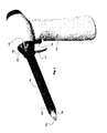
FIG. 1 is a perspective view of the integrated morsellator; -
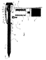
FIG. 2 is a side sectional view of the integrated morsellator; -
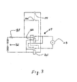
FIG. 3 is a schematic diagram of the control circuit of the morsellator. -
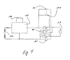
FIG. 4 is a schematic diagram of another embodiment of the control circuit. - Referring to the
Figures 1-4 for a clearer understanding of the invention, it may be seen that the preferred embodiment of the invention contemplates a fullydisposable morcellator 11.Morcellator 11 includes atubular cutting tube 101 which extends from a pistol grip typeplastic housing 124 and defines alumen 102 there through.Housing 124 contains analkaline battery package 112 powering an enclosedmotor 113. Themotor 113 drives a toothed wheel orgear 114 which engages asecond gear 103 formed on aradial extension 104 of ahub 106 as a part of the 90 degree gear 115 which rotates thecutting tube 101.Hub 106 includes an elongated tubular portion 107 within whichcutting tube 101 is received and secured andradial extension 104.Cutting tube 101 is made from thin wall stainless steel or other acceptable metallic tube and is ground at the distal end to be as sharp as possible.Hub 106 is preferably made from plastic, thus the two parts are mechanically joined together with any suitable means such as fasteners or an adhesive that prevents any longitudinal or annular displacement between the two parts. Plastic includes any rigid polymer that will hold the cutting tube in place despite longitudinal forces applied to it during the surgery. It will be understood that any other suitable means of joining the cutting tube to the hub may be employed however, the tube must not be displaced longitudinally in the hub during use.. The secured end ofhub 106 is also fitted with a sealing device such as aduckbill housing 125 which is rigidly secured tohousing 124. Theduckbill housing 125 avoids or minimizes gas leakage during the procedure. The duckbill house encompasses aduckbill seal 127 and a sealing disc 128. Theduckbill seal 127 stops gas leakage when no forceps or instrument are inserted through thelumen 102 of the morcellator and the disc 128 stops leakage when the forceps are inserted through thelumen 102. - Hub 106 is rotatably mounted within
housing 124 on abearing 131 supported ongussets 132 such that thehub 106 and thus thecutting tube 101 are restrained from axial movement. Aseal 133 prevents leakage about thehub 106 at bearing 131. The opposite end ofhub 106 is mounted for rotation on bearing 136 inflange 137 onduckbill housing 125 such thatlumen 102 is in communication with the interior ofduckbill housing 125. - The
morcellator 11 includes a built introcar 122 which means that the morcellator in companion with theobturator 123 can be introduced through an incision without the necessity of a separate trocar. Trocar 122 is rotatably mounted tohousing 124 such that by rotatingtrocar 122 it is movable axially alongcutting tube 101 to cover more or less of the sharp distal end of thecutting tube 101. Preferably,trocar 122 can be adjusted usingintegral knob 139 to at least three positions. In the SAFE position the trocar completely shields thecutting tube 101 and the morcellator is safe and ready to be introduced through the incision in the abdomen, Cut 1 exposes the cutting edge ofcutting tube 101, and Cut 2 retracts the trocar such that only an arc of the cutting edge is exposed. Preferentially,knob 139 is selectively turned to each position and is retentively held at that position by a detent and ball or other locking mechanism. In one embodiment, thetrocar 122 and knob cooperate with atrigger guard 141 which is attached tohousing 124 below atrigger switch 146 and extends outwardly to a free end 142 which engages slots inknob 139. To rotate thetrocar 122 the trigger guard end 142 is disengaged and then re-engaged in a selectedslot 143. The longitudinal movement of thetrocar 122 is created by the interaction of theknob 139 with a cam surface such as aprotrusion 155 formed onhousing 124 and engaged in aslot 156 inknob 139. Various other camming combinations are contemplated. - As will be seen in
Fig. 1 , the distal end 152 oftrocar 122 is beveled and angled such that one side of the end of the trocar forms an elipse with the result that one side of the trocar is shorter than the other. As a result, one side of cuttingtube 101 can be exposed without exposing the entire end of cuttingtube 101. This feature enables the longitudinal movement oftrocar 122 to selectively expose the cuttingtube 101. The partial setting, or Cut 2 setting, is to be used when the surgeon wants to use the morcellator to engage the uterus at a selective area on the cutting tube. At the partial setting the sharp end of the cutting tube is partly shown. The Cut 1, or full, setting fully exposes the cutting edge of the cutting tube and is used when the surgeon wants to core out strips of tissue - The
battery package 112 andmotor 113 are electrically connected through a printedcircuit board 117.Trigger 146 is mechanically coupled connected to twoswitches - Referring to
Fig 2 to 4 , thebattery package 112 is preferably a 9V single use battery package including six 1.5V 2500mAH batteries connected in series connected with a overload protecting fuse or diode 188 such as an S175. It will be appreciated that any suitable battery can be used. The battery package is wrapped in plastic (shrink tube) and fitted with 0.5mm2 leads. - The
relays trigger 146 is released andswitches - As seen in
Fig 4 the voltage across the motor can be increased to give two speed operation usingvoltage booster 175 which may be a PCB mounted circuit or a supplemental battery selectively connected in series. Aboost switch 176 can be separately actuated or can be incorporated as a second level of the depression oftrigger 146. - The apparatus as described and illustrated is intended for one use on one patient and is not intended to be sterilized or reused, thus, the cutting tube is not replaceable or interchangeable and the batteries are not replaceable or rechargeable. However, the design is sufficiently light weight and compact as to allow the surgeon to comfortably manipulate the instrument during the procedure without cumbersome cords or drive cables. It is to be understood that the form of the invention shown is a preferred embodiment thereof and that various changes and modifications may be made therein without departing from the scope of the invention as defined in the following claims.
Claims (6)
- A disposable laparoscopic morcellator for removing tissue from within a living organism through a small incision comprising in combination:an elongated cylinder (101) having a first end sharpened to form a cutting edge;a trocar (122) whereby the morcellator in companion with an obturator (123) can be introduced through an incision, the trocar mounted coaxially with said cylinder and movable longitudinally to selectively expose said cutting edge for selective engagement with tissue to be cut;a housing adapted to be held in one hand of a surgeon supporting said elongated cylinder for rotation about the longitudinal axis of said cylinder and supporting said trocar for selective linear movement along said cylinder, said housing providing access to the interior of said cylinder for removal of tissue there through; characterized bya motor (113) mounted in said housing for selectively rotating said cylinder; and,a battery (112) mounted within said housing and operably connected to supply power to said motor;wherein the apparatus is a fully integrated one piece device for surgical gynaecological and urological field, and intended for a single use;wherein the morcellator further comprises a switch mounted on said housing and electrically connected between said motor and said battery so as to connect opposing wiring in said motor to prevent rotation of said motor when said motor is not energized through said switch.
- An apparatus as described in claim 1 wherein said trocar (122) can be selectively fixed in at least one position exposing at least a portion of said cutting edge and in a position exposing none of said cutting edge ..
- Apparatus as described in claim 2 further comprising a cam surface formed on said housing proximal and cooperative with said trocar such that rotation of said trocar about said cylindrical tube cams said trocar between said positions.
- Apparatus as described in claim 3 further comprising a plurality of annufarly spaced recesses formed on said trocar proximal said housing and a locking member formed on said housing for selectively engaging one of said recesses to selectively fix said trocar in relation to said cam surface.
- Apparatus as described in claim 4 wherein said locking member is a guard for a human actuable switch for controlling said morcellator, wherein said guard is selectively movable into engagement with one of said plurality of recesses.
- Apparatus as described in claim 1, wherein said cylindrical tube is captured within a drive sleeve said drive sleeve mounted for rotation in a bearing surface in said housing and restrained from axial motion within said housing by internal gussets formed in said grip.
Applications Claiming Priority (2)
| Application Number | Priority Date | Filing Date | Title |
|---|---|---|---|
| US12/836,957 US9168057B2 (en) | 2010-07-15 | 2010-07-15 | Surgical apparatus |
| PCT/IB2011/001574 WO2012007812A1 (en) | 2010-07-15 | 2011-07-06 | Laparoscopic morcellator |
Publications (2)
| Publication Number | Publication Date |
|---|---|
| EP2593025A1 EP2593025A1 (en) | 2013-05-22 |
| EP2593025B1 true EP2593025B1 (en) | 2014-12-10 |
Family
ID=44534505
Family Applications (1)
| Application Number | Title | Priority Date | Filing Date |
|---|---|---|---|
| EP11749907.9A Active EP2593025B1 (en) | 2010-07-15 | 2011-07-06 | Laparoscopic morcellator |
Country Status (3)
| Country | Link |
|---|---|
| US (1) | US9168057B2 (en) |
| EP (1) | EP2593025B1 (en) |
| WO (1) | WO2012007812A1 (en) |
Families Citing this family (16)
| Publication number | Priority date | Publication date | Assignee | Title |
|---|---|---|---|---|
| DE102012221748A1 (en) * | 2012-11-28 | 2014-05-28 | Robert Bosch Gmbh | Hand tool |
| US9539018B2 (en) | 2013-07-11 | 2017-01-10 | Covidien Lp | Devices, systems, and methods for tissue morcellation |
| EP3766440A1 (en) | 2014-09-18 | 2021-01-20 | Mayo Foundation for Medical Education and Research | Soft tissue cutting device |
| CA2935398A1 (en) * | 2015-07-31 | 2017-01-31 | Rolls-Royce Corporation | Turbine airfoils with micro cooling features |
| RU2608623C1 (en) * | 2015-10-20 | 2017-01-23 | Общество с ограниченной ответственностью "Хирургические инновационные технологии" (ООО "Хирургические инновационные технологии") | Replaceable head piece to electrode-knife of placemaker for dissection of cicatricial tissues surrounding the extravascular fragment of placemaker electrode (versions) |
| US11071562B2 (en) * | 2016-02-25 | 2021-07-27 | Lalu Joseph | Reusable universal tissue morcellator system |
| US10987131B2 (en) | 2017-05-25 | 2021-04-27 | Coopersurgical, Inc. | Tissue containment systems and related methods |
| CN109419546A (en) * | 2017-08-31 | 2019-03-05 | 重庆西山科技股份有限公司 | Stapler power handle |
| CN109419545A (en) * | 2017-08-31 | 2019-03-05 | 重庆西山科技股份有限公司 | The dynamic structure of stapler power handle |
| US10864055B2 (en) | 2017-10-13 | 2020-12-15 | Sonex Health, Inc. | Tray for a soft tissue cutting device and methods of use |
| US10918409B2 (en) | 2017-12-05 | 2021-02-16 | Covidien Lp | Morcellator with auger tissue feeder |
| US10952787B2 (en) | 2017-12-07 | 2021-03-23 | Covidien Lp | Energy-based surgical device and system facilitating tissue removal |
| US11937845B2 (en) | 2019-01-11 | 2024-03-26 | Mayo Foundation For Medical Education And Research | Micro-invasive surgical device and methods of use |
| USD981563S1 (en) * | 2019-10-11 | 2023-03-21 | Aok Innovations, Llc | Chest tube insertion aid and handle assembly |
| TWM614039U (en) * | 2021-03-10 | 2021-07-01 | 康健生醫科技股份有限公司 | Rotary cutter with locking device |
| USD989961S1 (en) | 2021-04-30 | 2023-06-20 | Sonex Health, Inc. | Soft tissue cutting device |
Family Cites Families (19)
| Publication number | Priority date | Publication date | Assignee | Title |
|---|---|---|---|---|
| US4108182A (en) * | 1977-02-16 | 1978-08-22 | Concept Inc. | Reciprocation vitreous suction cutter head |
| US4796624A (en) * | 1986-11-19 | 1989-01-10 | Concept, Inc. | Lashliner |
| DE9114443U1 (en) | 1991-01-25 | 1992-01-23 | Wisap Gesellschaft Fuer Wissenschaftlichen Apparatebau Mbh, 8029 Sauerlach, De | |
| US5814044A (en) | 1995-02-10 | 1998-09-29 | Enable Medical Corporation | Apparatus and method for morselating and removing tissue from a patient |
| US5957888A (en) * | 1995-10-10 | 1999-09-28 | United States Surgical Corporation | Surgical cannula having a variable length |
| US6039748A (en) | 1997-08-05 | 2000-03-21 | Femrx, Inc. | Disposable laparoscopic morcellator |
| US5916198A (en) | 1997-08-05 | 1999-06-29 | Femrx, Inc. | Non-binding surgical valve |
| US6245084B1 (en) * | 1998-10-20 | 2001-06-12 | Promex, Inc. | System for controlling a motor driven surgical cutting instrument |
| US6277135B1 (en) * | 2000-03-17 | 2001-08-21 | Kuen-Chyr Wang | Driven rotary incision scalpel |
| US20040066008A1 (en) * | 2002-10-04 | 2004-04-08 | Smith Robert C. | Introducer seal assembly |
| AU2003231939A1 (en) * | 2002-05-31 | 2003-12-19 | Vidacare Corporation | Apparatus and method to access the bone marrow |
| US20040092992A1 (en) * | 2002-10-23 | 2004-05-13 | Kenneth Adams | Disposable battery powered rotary tissue cutting instruments and methods therefor |
| US8573462B2 (en) * | 2006-05-19 | 2013-11-05 | Ethicon Endo-Surgery, Inc. | Electrical surgical instrument with optimized power supply and drive |
| EP1912574A4 (en) * | 2005-08-10 | 2010-08-04 | Insight Instr Inc | Tool for extracting vitreous samples from an eye |
| US8216246B2 (en) * | 2006-08-09 | 2012-07-10 | Insight Instruments Inc. | Retractable tip for vitrectomy tool |
| US8100928B2 (en) * | 2006-08-10 | 2012-01-24 | Ethicon, Inc. | Morcellator with detachable handle |
| US20080039883A1 (en) * | 2006-08-10 | 2008-02-14 | Nohilly Martin J | Anti-coring device for a surgical morcellator |
| WO2008128186A1 (en) * | 2007-04-12 | 2008-10-23 | Applied Medical Resources Corporation | Method and apparatus for tissue morcellation |
| DE102007044956B4 (en) | 2007-09-19 | 2016-01-21 | Olympus Winter & Ibe Gmbh | Laparoscopic morcellator with tube and protective tube |
-
2010
- 2010-07-15 US US12/836,957 patent/US9168057B2/en active Active
-
2011
- 2011-07-06 EP EP11749907.9A patent/EP2593025B1/en active Active
- 2011-07-06 WO PCT/IB2011/001574 patent/WO2012007812A1/en active Application Filing
Also Published As
| Publication number | Publication date |
|---|---|
| EP2593025A1 (en) | 2013-05-22 |
| WO2012007812A1 (en) | 2012-01-19 |
| US20120016399A1 (en) | 2012-01-19 |
| US9168057B2 (en) | 2015-10-27 |
Similar Documents
| Publication | Publication Date | Title |
|---|---|---|
| EP2593025B1 (en) | Laparoscopic morcellator | |
| US8152820B2 (en) | Medical device and method for human tissue and foreign body extraction | |
| US10307204B2 (en) | Integrated bailout for motorized RF device | |
| US10143514B2 (en) | Electronic bailout for motorized RF device | |
| EP3530219B1 (en) | Ultrasonic surgical instrument with torque assist feature | |
| US5857982A (en) | Apparatus and method for removing tissue | |
| US8998939B2 (en) | Surgical instrument with modular end effector | |
| EP2635220B1 (en) | Surgical instrument with modular end effector | |
| US10085792B2 (en) | Surgical instrument with motorized attachment feature | |
| JP6840731B2 (en) | Ultrasonic surgical instrument with slidable flexion activation member | |
| US11871950B2 (en) | Tissue resecting device including a motor cooling assembly | |
| CN111714188A (en) | Tissue removal instrument incorporating rotational locking feature | |
| CN109862855A (en) | Equipment for organizing to remove | |
| US8840596B2 (en) | Removable suction assembly for medical handpieces | |
| US11452540B2 (en) | Wireless tissue dissector | |
| US11571254B2 (en) | Device for laparoscopic surgery | |
| EP3643262B1 (en) | Tissue resecting device including a blade lock and release mechanism | |
| US11129672B2 (en) | Tissue resecting device including an articulatable cutting member | |
| US11571232B2 (en) | Corkscrew tissue resecting device | |
| EP3888572A1 (en) | Tissue resecting device with deflecting tip |
Legal Events
| Date | Code | Title | Description |
|---|---|---|---|
| PUAI | Public reference made under article 153(3) epc to a published international application that has entered the european phase |
Free format text: ORIGINAL CODE: 0009012 |
|
| 17P | Request for examination filed |
Effective date: 20130215 |
|
| AK | Designated contracting states |
Kind code of ref document: A1 Designated state(s): AL AT BE BG CH CY CZ DE DK EE ES FI FR GB GR HR HU IE IS IT LI LT LU LV MC MK MT NL NO PL PT RO RS SE SI SK SM TR |
|
| 17Q | First examination report despatched |
Effective date: 20131104 |
|
| GRAP | Despatch of communication of intention to grant a patent |
Free format text: ORIGINAL CODE: EPIDOSNIGR1 |
|
| INTG | Intention to grant announced |
Effective date: 20140619 |
|
| GRAS | Grant fee paid |
Free format text: ORIGINAL CODE: EPIDOSNIGR3 |
|
| GRAA | (expected) grant |
Free format text: ORIGINAL CODE: 0009210 |
|
| RAP1 | Party data changed (applicant data changed or rights of an application transferred) |
Owner name: KEBOMED AG |
|
| RIN1 | Information on inventor provided before grant (corrected) |
Inventor name: POULSEN, HENRIK BISGAARD |
|
| AK | Designated contracting states |
Kind code of ref document: B1 Designated state(s): AL AT BE BG CH CY CZ DE DK EE ES FI FR GB GR HR HU IE IS IT LI LT LU LV MC MK MT NL NO PL PT RO RS SE SI SK SM TR |
|
| REG | Reference to a national code |
Ref country code: GB Ref legal event code: FG4D |
|
| REG | Reference to a national code |
Ref country code: CH Ref legal event code: EP |
|
| REG | Reference to a national code |
Ref country code: IE Ref legal event code: FG4D |
|
| REG | Reference to a national code |
Ref country code: AT Ref legal event code: REF Ref document number: 700257 Country of ref document: AT Kind code of ref document: T Effective date: 20150115 |
|
| REG | Reference to a national code |
Ref country code: DE Ref legal event code: R096 Ref document number: 602011012149 Country of ref document: DE Effective date: 20150122 |
|
| REG | Reference to a national code |
Ref country code: AT Ref legal event code: MK05 Ref document number: 700257 Country of ref document: AT Kind code of ref document: T Effective date: 20141210 Ref country code: NL Ref legal event code: VDEP Effective date: 20141210 |
|
| REG | Reference to a national code |
Ref country code: NL Ref legal event code: VDEP Effective date: 20141210 |
|
| PG25 | Lapsed in a contracting state [announced via postgrant information from national office to epo] |
Ref country code: ES Free format text: LAPSE BECAUSE OF FAILURE TO SUBMIT A TRANSLATION OF THE DESCRIPTION OR TO PAY THE FEE WITHIN THE PRESCRIBED TIME-LIMIT Effective date: 20141210 Ref country code: NO Free format text: LAPSE BECAUSE OF FAILURE TO SUBMIT A TRANSLATION OF THE DESCRIPTION OR TO PAY THE FEE WITHIN THE PRESCRIBED TIME-LIMIT Effective date: 20150310 Ref country code: FI Free format text: LAPSE BECAUSE OF FAILURE TO SUBMIT A TRANSLATION OF THE DESCRIPTION OR TO PAY THE FEE WITHIN THE PRESCRIBED TIME-LIMIT Effective date: 20141210 Ref country code: LT Free format text: LAPSE BECAUSE OF FAILURE TO SUBMIT A TRANSLATION OF THE DESCRIPTION OR TO PAY THE FEE WITHIN THE PRESCRIBED TIME-LIMIT Effective date: 20141210 |
|
| REG | Reference to a national code |
Ref country code: LT Ref legal event code: MG4D |
|
| PG25 | Lapsed in a contracting state [announced via postgrant information from national office to epo] |
Ref country code: LV Free format text: LAPSE BECAUSE OF FAILURE TO SUBMIT A TRANSLATION OF THE DESCRIPTION OR TO PAY THE FEE WITHIN THE PRESCRIBED TIME-LIMIT Effective date: 20141210 Ref country code: GR Free format text: LAPSE BECAUSE OF FAILURE TO SUBMIT A TRANSLATION OF THE DESCRIPTION OR TO PAY THE FEE WITHIN THE PRESCRIBED TIME-LIMIT Effective date: 20150311 Ref country code: AT Free format text: LAPSE BECAUSE OF FAILURE TO SUBMIT A TRANSLATION OF THE DESCRIPTION OR TO PAY THE FEE WITHIN THE PRESCRIBED TIME-LIMIT Effective date: 20141210 Ref country code: RS Free format text: LAPSE BECAUSE OF FAILURE TO SUBMIT A TRANSLATION OF THE DESCRIPTION OR TO PAY THE FEE WITHIN THE PRESCRIBED TIME-LIMIT Effective date: 20141210 Ref country code: SE Free format text: LAPSE BECAUSE OF FAILURE TO SUBMIT A TRANSLATION OF THE DESCRIPTION OR TO PAY THE FEE WITHIN THE PRESCRIBED TIME-LIMIT Effective date: 20141210 Ref country code: HR Free format text: LAPSE BECAUSE OF FAILURE TO SUBMIT A TRANSLATION OF THE DESCRIPTION OR TO PAY THE FEE WITHIN THE PRESCRIBED TIME-LIMIT Effective date: 20141210 |
|
| PG25 | Lapsed in a contracting state [announced via postgrant information from national office to epo] |
Ref country code: NL Free format text: LAPSE BECAUSE OF FAILURE TO SUBMIT A TRANSLATION OF THE DESCRIPTION OR TO PAY THE FEE WITHIN THE PRESCRIBED TIME-LIMIT Effective date: 20141210 |
|
| PG25 | Lapsed in a contracting state [announced via postgrant information from national office to epo] |
Ref country code: EE Free format text: LAPSE BECAUSE OF FAILURE TO SUBMIT A TRANSLATION OF THE DESCRIPTION OR TO PAY THE FEE WITHIN THE PRESCRIBED TIME-LIMIT Effective date: 20141210 Ref country code: PT Free format text: LAPSE BECAUSE OF FAILURE TO SUBMIT A TRANSLATION OF THE DESCRIPTION OR TO PAY THE FEE WITHIN THE PRESCRIBED TIME-LIMIT Effective date: 20150410 Ref country code: RO Free format text: LAPSE BECAUSE OF FAILURE TO SUBMIT A TRANSLATION OF THE DESCRIPTION OR TO PAY THE FEE WITHIN THE PRESCRIBED TIME-LIMIT Effective date: 20141210 Ref country code: CZ Free format text: LAPSE BECAUSE OF FAILURE TO SUBMIT A TRANSLATION OF THE DESCRIPTION OR TO PAY THE FEE WITHIN THE PRESCRIBED TIME-LIMIT Effective date: 20141210 Ref country code: SK Free format text: LAPSE BECAUSE OF FAILURE TO SUBMIT A TRANSLATION OF THE DESCRIPTION OR TO PAY THE FEE WITHIN THE PRESCRIBED TIME-LIMIT Effective date: 20141210 |
|
| PGFP | Annual fee paid to national office [announced via postgrant information from national office to epo] |
Ref country code: CH Payment date: 20150617 Year of fee payment: 5 |
|
| REG | Reference to a national code |
Ref country code: FR Ref legal event code: PLFP Year of fee payment: 5 |
|
| PG25 | Lapsed in a contracting state [announced via postgrant information from national office to epo] |
Ref country code: PL Free format text: LAPSE BECAUSE OF FAILURE TO SUBMIT A TRANSLATION OF THE DESCRIPTION OR TO PAY THE FEE WITHIN THE PRESCRIBED TIME-LIMIT Effective date: 20141210 Ref country code: IS Free format text: LAPSE BECAUSE OF FAILURE TO SUBMIT A TRANSLATION OF THE DESCRIPTION OR TO PAY THE FEE WITHIN THE PRESCRIBED TIME-LIMIT Effective date: 20150410 |
|
| REG | Reference to a national code |
Ref country code: DE Ref legal event code: R097 Ref document number: 602011012149 Country of ref document: DE |
|
| PLBE | No opposition filed within time limit |
Free format text: ORIGINAL CODE: 0009261 |
|
| STAA | Information on the status of an ep patent application or granted ep patent |
Free format text: STATUS: NO OPPOSITION FILED WITHIN TIME LIMIT |
|
| PG25 | Lapsed in a contracting state [announced via postgrant information from national office to epo] |
Ref country code: DK Free format text: LAPSE BECAUSE OF FAILURE TO SUBMIT A TRANSLATION OF THE DESCRIPTION OR TO PAY THE FEE WITHIN THE PRESCRIBED TIME-LIMIT Effective date: 20141210 |
|
| 26N | No opposition filed |
Effective date: 20150911 |
|
| PG25 | Lapsed in a contracting state [announced via postgrant information from national office to epo] |
Ref country code: IT Free format text: LAPSE BECAUSE OF FAILURE TO SUBMIT A TRANSLATION OF THE DESCRIPTION OR TO PAY THE FEE WITHIN THE PRESCRIBED TIME-LIMIT Effective date: 20141210 |
|
| PG25 | Lapsed in a contracting state [announced via postgrant information from national office to epo] |
Ref country code: SI Free format text: LAPSE BECAUSE OF FAILURE TO SUBMIT A TRANSLATION OF THE DESCRIPTION OR TO PAY THE FEE WITHIN THE PRESCRIBED TIME-LIMIT Effective date: 20141210 Ref country code: MC Free format text: LAPSE BECAUSE OF FAILURE TO SUBMIT A TRANSLATION OF THE DESCRIPTION OR TO PAY THE FEE WITHIN THE PRESCRIBED TIME-LIMIT Effective date: 20141210 |
|
| PG25 | Lapsed in a contracting state [announced via postgrant information from national office to epo] |
Ref country code: LU Free format text: LAPSE BECAUSE OF FAILURE TO SUBMIT A TRANSLATION OF THE DESCRIPTION OR TO PAY THE FEE WITHIN THE PRESCRIBED TIME-LIMIT Effective date: 20150706 |
|
| REG | Reference to a national code |
Ref country code: IE Ref legal event code: MM4A |
|
| PG25 | Lapsed in a contracting state [announced via postgrant information from national office to epo] |
Ref country code: BE Free format text: LAPSE BECAUSE OF FAILURE TO SUBMIT A TRANSLATION OF THE DESCRIPTION OR TO PAY THE FEE WITHIN THE PRESCRIBED TIME-LIMIT Effective date: 20141210 |
|
| REG | Reference to a national code |
Ref country code: FR Ref legal event code: PLFP Year of fee payment: 6 |
|
| PG25 | Lapsed in a contracting state [announced via postgrant information from national office to epo] |
Ref country code: IE Free format text: LAPSE BECAUSE OF NON-PAYMENT OF DUE FEES Effective date: 20150706 |
|
| REG | Reference to a national code |
Ref country code: CH Ref legal event code: PL |
|
| PG25 | Lapsed in a contracting state [announced via postgrant information from national office to epo] |
Ref country code: MT Free format text: LAPSE BECAUSE OF FAILURE TO SUBMIT A TRANSLATION OF THE DESCRIPTION OR TO PAY THE FEE WITHIN THE PRESCRIBED TIME-LIMIT Effective date: 20141210 |
|
| PG25 | Lapsed in a contracting state [announced via postgrant information from national office to epo] |
Ref country code: LI Free format text: LAPSE BECAUSE OF NON-PAYMENT OF DUE FEES Effective date: 20160731 Ref country code: CH Free format text: LAPSE BECAUSE OF NON-PAYMENT OF DUE FEES Effective date: 20160731 |
|
| PG25 | Lapsed in a contracting state [announced via postgrant information from national office to epo] |
Ref country code: BG Free format text: LAPSE BECAUSE OF FAILURE TO SUBMIT A TRANSLATION OF THE DESCRIPTION OR TO PAY THE FEE WITHIN THE PRESCRIBED TIME-LIMIT Effective date: 20141210 Ref country code: SM Free format text: LAPSE BECAUSE OF FAILURE TO SUBMIT A TRANSLATION OF THE DESCRIPTION OR TO PAY THE FEE WITHIN THE PRESCRIBED TIME-LIMIT Effective date: 20141210 Ref country code: HU Free format text: LAPSE BECAUSE OF FAILURE TO SUBMIT A TRANSLATION OF THE DESCRIPTION OR TO PAY THE FEE WITHIN THE PRESCRIBED TIME-LIMIT; INVALID AB INITIO Effective date: 20110706 |
|
| PG25 | Lapsed in a contracting state [announced via postgrant information from national office to epo] |
Ref country code: CY Free format text: LAPSE BECAUSE OF FAILURE TO SUBMIT A TRANSLATION OF THE DESCRIPTION OR TO PAY THE FEE WITHIN THE PRESCRIBED TIME-LIMIT Effective date: 20141210 |
|
| REG | Reference to a national code |
Ref country code: FR Ref legal event code: PLFP Year of fee payment: 7 |
|
| PG25 | Lapsed in a contracting state [announced via postgrant information from national office to epo] |
Ref country code: TR Free format text: LAPSE BECAUSE OF FAILURE TO SUBMIT A TRANSLATION OF THE DESCRIPTION OR TO PAY THE FEE WITHIN THE PRESCRIBED TIME-LIMIT Effective date: 20141210 |
|
| PG25 | Lapsed in a contracting state [announced via postgrant information from national office to epo] |
Ref country code: MK Free format text: LAPSE BECAUSE OF FAILURE TO SUBMIT A TRANSLATION OF THE DESCRIPTION OR TO PAY THE FEE WITHIN THE PRESCRIBED TIME-LIMIT Effective date: 20141210 |
|
| REG | Reference to a national code |
Ref country code: FR Ref legal event code: PLFP Year of fee payment: 8 |
|
| REG | Reference to a national code |
Ref country code: DE Ref legal event code: R081 Ref document number: 602011012149 Country of ref document: DE Owner name: LINA MEDICAL INTERNATIONAL OPERATIONS AG, CH Free format text: FORMER OWNER: KEBOMED AG, ROOT LAENGENBOLD, CH |
|
| PG25 | Lapsed in a contracting state [announced via postgrant information from national office to epo] |
Ref country code: AL Free format text: LAPSE BECAUSE OF FAILURE TO SUBMIT A TRANSLATION OF THE DESCRIPTION OR TO PAY THE FEE WITHIN THE PRESCRIBED TIME-LIMIT Effective date: 20141210 |
|
| PGFP | Annual fee paid to national office [announced via postgrant information from national office to epo] |
Ref country code: GB Payment date: 20230717 Year of fee payment: 13 |
|
| PGFP | Annual fee paid to national office [announced via postgrant information from national office to epo] |
Ref country code: FR Payment date: 20230724 Year of fee payment: 13 Ref country code: DE Payment date: 20230719 Year of fee payment: 13 |