EP2592300A1 - Vibration isolation system - Google Patents
Vibration isolation system Download PDFInfo
- Publication number
- EP2592300A1 EP2592300A1 EP11195436.8A EP11195436A EP2592300A1 EP 2592300 A1 EP2592300 A1 EP 2592300A1 EP 11195436 A EP11195436 A EP 11195436A EP 2592300 A1 EP2592300 A1 EP 2592300A1
- Authority
- EP
- European Patent Office
- Prior art keywords
- piston
- tuning
- magnet member
- vibration isolator
- fluid
- Prior art date
- Legal status (The legal status is an assumption and is not a legal conclusion. Google has not performed a legal analysis and makes no representation as to the accuracy of the status listed.)
- Granted
Links
Images




Classifications
-
- F—MECHANICAL ENGINEERING; LIGHTING; HEATING; WEAPONS; BLASTING
- F16—ENGINEERING ELEMENTS AND UNITS; GENERAL MEASURES FOR PRODUCING AND MAINTAINING EFFECTIVE FUNCTIONING OF MACHINES OR INSTALLATIONS; THERMAL INSULATION IN GENERAL
- F16F—SPRINGS; SHOCK-ABSORBERS; MEANS FOR DAMPING VIBRATION
- F16F13/00—Units comprising springs of the non-fluid type as well as vibration-dampers, shock-absorbers, or fluid springs
- F16F13/04—Units comprising springs of the non-fluid type as well as vibration-dampers, shock-absorbers, or fluid springs comprising both a plastics spring and a damper, e.g. a friction damper
- F16F13/06—Units comprising springs of the non-fluid type as well as vibration-dampers, shock-absorbers, or fluid springs comprising both a plastics spring and a damper, e.g. a friction damper the damper being a fluid damper, e.g. the plastics spring not forming a part of the wall of the fluid chamber of the damper
- F16F13/24—Units comprising springs of the non-fluid type as well as vibration-dampers, shock-absorbers, or fluid springs comprising both a plastics spring and a damper, e.g. a friction damper the damper being a fluid damper, e.g. the plastics spring not forming a part of the wall of the fluid chamber of the damper the central part of the unit being supported by one element and both extremities of the unit being supported by a single other element, i.e. double acting mounting
-
- B—PERFORMING OPERATIONS; TRANSPORTING
- B64—AIRCRAFT; AVIATION; COSMONAUTICS
- B64C—AEROPLANES; HELICOPTERS
- B64C27/00—Rotorcraft; Rotors peculiar thereto
- B64C27/001—Vibration damping devices
- B64C2027/002—Vibration damping devices mounted between the rotor drive and the fuselage
Definitions
- the present application relates in general to active vibration control. More specifically, the present application relates to a system for isolating mechanical vibrations in structures or bodies that are subject to harmonic or oscillating displacements or forces.
- the system of the present application is well suited for use in the field of aircraft, in particular, helicopters and other rotary wing aircraft.
- Typical vibration isolation and attenuation devices employ various combinations of the mechanical system elements (springs and mass) to adjust the frequency response characteristics of the overall system to achieve acceptable levels of vibration in the structures of interest in the system.
- vibration-isolation systems are utilized to isolate the fuselage or other portions of an aircraft from mechanical vibrations, such as harmonic vibrations, which are associated with the propulsion system, and which arise from the engine, transmission, and propellers or rotors of the aircraft.
- Vibration isolators are distinguishable from damping devices in the prior art that are erroneously referred to as "isolators.”
- a vibration isolator utilizes inertial forces (m ⁇ ) to cancel elastic forces ( kx ).
- a damping device is concerned with utilizing dissipative effects (c ⁇ ) to remove energy from a vibrating system.
- Halwes '607 discloses a vibration isolator, in which a dense, low-viscosity fluid is used as the "tuning" mass to counterbalance, or cancel, oscillating forces transmitted through the isolator. This isolator employs the principle that the acceleration of an oscillating mass is 180° out of phase with its displacement.
- Halwes '607 it was recognized that the inertial characteristics of a dense, low-viscosity fluid, combined with a hydraulic advantage resulting from a piston arrangement, could harness the out-of-phase acceleration to generate counter-balancing forces to attenuate or cancel vibration. Halwes '607 provided a much more compact, reliable, and efficient isolator than was provided in the prior art.
- the original dense, low-viscosity fluid contemplated by Halwes '607 was mercury, which is toxic and highly corrosive.
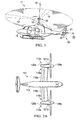
- Helicopter 11 has a fuselage 13 and a main rotor assembly 15, including main rotor blades 17 and a main rotor mast 18. Helicopter 11 has a tail rotor assembly 19, including tail rotor blades 21 and a tail rotor mast 20.
- Main rotor blades 17 generally rotate about a vertical axis 16 of main rotor mast 18.
- Tail rotor blades 21 generally rotate about a lateral axis 22 of tail rotor mast 20.
- Helicopter 11 also includes a vibration isolation system according to the present application for isolating fuselage 13 or other portions of helicopter 11 from mechanical vibrations, such as harmonic vibrations, which are associated with the propulsion system and which arise from the engine, transmission, and rotors of helicopter 11.
- mechanical vibrations such as harmonic vibrations
- the vibration isolation system of the present application may also be utilized on other types of rotary wing aircraft.
- a tilt rotor aircraft 111 according to the present application is illustrated.
- rotor assemblies 113a and 113b are carried by wings 115a and 115b, and are disposed at end portions 116a and 116b of wings 115a and 115b, respectively.
- Tilt rotor assemblies 113a and 113b include nacelles 120a and 120b, which carry the engines and transmissions of tilt rotor aircraft 111, as well as, rotor hubs 119a and 119b on forward ends 121a and 121b of tilt rotor assemblies 113a and 113b, respectively.
- Tilt rotor assemblies 113a and 113b move or rotate relative to wing members 115a and 115b between a helicopter mode in which tilt rotor assemblies 113a and 113b are tilted upward, such that tilt rotor aircraft 111 flies like a conventional helicopter; and an airplane mode in which tilt rotor assemblies 113a and 113b are tilted forward, such that tilt rotor aircraft 111 flies like a conventional propeller driven aircraft.
- tilt rotor aircraft 111 is shown in the airplane mode
- Figure 2B tilt rotor aircraft 111 is shown in the helicopter mode.
- wings 115a and 115b are coupled to a fuselage 114.
- Tilt rotor aircraft 111 also includes a vibration isolation system according to the present application for isolating fuselage 114 or other portions of tilt rotor aircraft 111 from mechanical vibrations, such as harmonic vibrations, which are associated with the propulsion system and which arise from the engines, transmissions, and rotors of tilt rotor aircraft 111.
- a vibration isolation system according to the present application for isolating fuselage 114 or other portions of tilt rotor aircraft 111 from mechanical vibrations, such as harmonic vibrations, which are associated with the propulsion system and which arise from the engines, transmissions, and rotors of tilt rotor aircraft 111.
- a quad tilt rotor aircraft 211 according to the present application is illustrated.
- rotor assemblies 213a, 213b, 213c, and 213d are carried by a forward wing 215a, 215c, and an aft wing 215b, 215d, respectively.
- Tilt rotor assemblies 213a, 213b, 213c, and 213d include nacelles 220a, 220b, 220c, and 220d, which carry the engines and transmissions of quad tilt rotor aircraft 211, as well as, rotor hubs 219a, 219b, 219c, and 219d on forward ends of tilt rotor assemblies 213a, 213b, 213c, and 213d, respectively.
- Tilt rotor assemblies 213a, 213b, 213c, and 213d move or rotate relative to wing members 215a, 215b, 215c, and 215d between a helicopter mode in which tilt rotor assemblies 213a, 213b, 213c, and 213d are tilted upward, such that quad tilt rotor aircraft 211 flies like a conventional helicopter; and an airplane mode in which tilt rotor assemblies 213a, 213b, 213c, and 213d are tilted forward, such that quad tilt rotor aircraft 211 flies like a conventional propeller driven aircraft.
- quad tilt rotor aircraft 111 is shown in the airplane mode.
- Tilt rotor aircraft 211 also includes a vibration isolation system according to the present application for isolating fuselage 214 or other portions of quad tilt rotor aircraft 211 from mechanical vibrations, such as harmonic vibrations, which are associated with the propulsion system and which arise from the engines, transmissions, and rotors of quad tilt rotor aircraft 211.
- vibration isolation system according to the present application for isolating fuselage 214 or other portions of quad tilt rotor aircraft 211 from mechanical vibrations, such as harmonic vibrations, which are associated with the propulsion system and which arise from the engines, transmissions, and rotors of quad tilt rotor aircraft 211.
- the present application may be used with any aircraft on which it would be desirable to have vibration isolation according to the present application, including unmanned aerial vehicles that are remotely piloted.
- Isolator 401 for use on an aircraft is illustrated.
- Isolator 401 includes a generally cylindrical housing 407.
- housing 407 is rigidly divided between an upper housing and a lower housing.
- a piston 411 of selected cross-sectional diameter is disposed within the interior of housing 407.
- Housing 407 is typically coupled to a fuselage 405 of an aircraft and piston 411 is typically coupled to the transmission and propulsion system of the aircraft (not shown) via a pylon assembly 403 at an attachment bracket 415.
- fuselage 405 serves as the body to be isolated from vibration
- pylon assembly 403 of the aircraft serves as the vibrating body.
- vibration isolator 401 is illustrated in a cross section view.
- An upper fluid chamber 413a is partially defined by the interior of an upper portion of housing 407.
- a lower fluid chamber 413b is partially defined by the interior of a lower portion of housing 407.
- Piston 411 is resiliently located against the upper and lower portions of housing 407 with elastomer members 409a and 409b, respectively.
- a tuning port or passage 419 extends centrally through piston 411 and permits a vibration-isolation fluid 417 to move between upper fluid chamber 413a and lower fluid chamber 413b, through tuning passage 419.
- the approximate length of tuning passage 419 is defined by T1 in Figure 4B .
- a conical flow diverter 421 is provided at each end of upper fluid chamber 413a and lower fluid chamber 413b and is aligned with and generally opposes the opening at each end of tuning passage 419.
- Each conical flow diverter 421 enhances fluid flow by decelerating the vibration-isolation fluid as it flows from each end of the fluid chamber into and out of tuning passage 419.
- a linear induction motor assembly 425 includes a magnet member 429 and inductance coils 427.
- Magnet member 429 is generally cylindrical with an interior surface forming tuning passage 419. Magnet member 429 is in contact at each end with an upper pumper piston 423a and a lower pumper piston 423b.
- Upper pumper piston 423a and lower pumper piston 423b are each cone shaped, the larger circular end being coupled to piston 411 with pumper elastomer members 431a and 431b, while the narrow end of upper pumper piston 423a and lower pumper piston 423b being in contact with magnet member 429.
- Vibration-isolation fluid 417 is preferably a high-density, low-viscosity fluid disposed within tuning passage 419 and fluid chambers 413a and 413b.
- elastomer members 409a and 409b function as a spring to permit piston 411 to move or oscillate relative to housing 407, while maintaining piston 411 in a central location in housing 407 when no load is applied.
- elastomer members 409a and 409b function at least as a spring to permit piston 411 to move or oscillate relative to housing 407.
- the introduction of a force into piston bracket 415 displaces piston 411 relative to housing 407 in a direction 437.
- piston 411 similarly oscillates relative to housing 407.
- Each oscillatory displacement of piston 411 relative to housing 407 similarly causes a displacement of upper pumper piston 423a and lower pumper piston 423b.
- a displacement of upper pumper piston 423a and lower pumper piston 423b in a first direction causes a displacement of tuning fluid through tuning passage 419 in the opposite direction of the displacement of piston 411.
- the displacement of piston 411 causes an oscillatory reaction force due to strain in elastomer members 409a and 409b.
- the volumes of vibration-isolation fluid 417 in fluid chambers 413a and 413b are alternately increased and decreased such that vibration-isolation fluid 417 is pumped back and forth through tuning passage 419.
- the inertial force created by acceleration of the mass of the vibration-isolation fluid 417 is out of phase of the force introduced to piston 411 via bracket 415.
- the force of the mass of the vibration-isolation fluid 417 cancels the force introduced to piston 411 via bracket 415.
- a small amount of undesirable damping can occur at the isolation frequency; thereby preventing complete force cancellation from occurring, as such, a small amount of vibratory force can sometimes be transferred from vibrating body 403 to isolated body 405.
- a passive isolation frequency of isolator 401 is in part, a function of the ratio of the effective piston area of upper pumper piston 423a and lower pumper piston 423b, to the diameter of tuning passage 419.
- the isolator 401 is sized so the isolation frequency cancels the predicted vibratory frequency of vibrating body 403.
- the vibratory frequency is typically the n/revolution frequency, where n is the number of rotor blades rotating around a mast axis of rotation at a certain rotational speed.
- some rotorcraft may be variable RPM rotorcraft, in that the rotorcraft can have the ability to operate in a range of rotor RPM's.
- other factors such as temperature, aging of elastomer members, tolerance variations, to name a few, make it desirable to actively change the isolation frequency of isolator 401.
- Isolator 401 is configured to actively change the isolation frequency with linear inductance motor assembly 425.
- Control system 435 is electrically coupled via electrical leads 433a and 433b to inductance coils 427 for selectively providing oscillatory forces to upper pumper piston 423a and lower pumper piston 423b, via magnet 429.
- linear inductance motor assembly 425 can actively adjust the isolation frequency of isolator 401 by modifying the acceleration of the vibration-isolation fluid 417, thereby modifying the inertial force of the vibration-isolation fluid 417 as it is accelerated back and forth through tuning passage 419.
- Control system 435 is configured to select the frequencies and the oscillatory forces imparted on upper pumper piston 423a and lower pumper piston 423b, via magnet 429. In this manner, the oscillatory vibrations from the vibrating body 403 are prevented from transferring to isolated body, even when the vibratory frequency of vibratory body 403 changes. Further, linear inductance motor assembly 425 can be operated to deepen the isolation frequency to negate any dampening losses.
- R represents the ratio of the effective cross sectional area of upper pumper piston 423a and lower pumper piston 423b, to the cross sectional area of tuning passage 419.
- Mass of tuning fluid 417 is represented by m t .
- the spring rate of elastomer members 409a and 409b is represented by K .
- the tunable vibration isolator of the present application is preferably used to isolate the vibration generated by the transmission and propulsion system of an aircraft, such as aircraft 11, 111, and 211, from the fuselage, such as fuselages 13, 114, and 214 (see Figures 1-3 ).
- aircraft such as aircraft 11, 111, and 211
- fuselage such as fuselages 13, 114, and 214
- FIG. 1 the tunable vibration isolator of the present application is described herein with respect to an aircraft application, it may be used in any application in which it is desirable to isolate the vibration between one body and another.
- the following discussion of the preferred embodiment of the present application will be with respect to an application of the tunable vibration isolator on a rotorcraft aircraft 11 (see Figure 1 ) to isolate the vibratory forces generated in a pylon from a fuselage.
- the fuselage is represented as the mass of the fuselage M fuselage , or box 405;
- the pylon is represented as the mass of the pylon M pylon , or box 403;
- a box 441 represents the mass of the tuning mass M t , which in the present embodiment can be vibration-isolation fluid disposed in the isolator.
- a vibratory force F ⁇ sin( ⁇ t) is generated by the propulsion system.
- a spring member represented by a spring 409a and 409b, is disposed between the fuselage M fuselage and the pylon M pylon .
- Spring 409a and 409b has a spring constant K.
- Tuning mass M t is operably associated with fuselage M fuselage and pylon M pylon .
- tuning mass M t functions as if cantilevered from a first fulcrum 443 attached to pylon member M pylon , and a second fulcrum 445 attached to the fuselage M fuselage .
- the distance a from first fulcrum 443 to second fulcrum 445 represents the cross-sectional area of the tuning passage
- the distance b from first fulcrum 443 to the tuning mass M t represents the effective cross-sectional area of a piston (see 423a and 423b in Figure 4B ), such that an area ratio, or hydraulic ratio, R is equal to the ratio of b to a.
- An active tuning element 425 is disposed between the pylon M pylon and the tuning mass M t . Active tuning element 425 functions to make fulcrum 443 vibrate. It should be understood that active tuning element 425 may represent a plurality of active tuning elements acting either together or independently. In the preferred embodiment, active tuning element is a linear inductance motor assembly.
- Active tuning element 425 can be represented by mechanical properties include a spring element 431a, 431b having a spring constant kp, a mass Mp, and a controllable force element 429.
- Controllable force element 429 may have any phase angle and be of any magnitude within the maximum capabilities of active tuning element 425.
- Active tuning element 425 also includes control circuitry for controlling the actuation of active tuning element 429. Active tuning element 425 allows for selective actuation of the tuning mass.
- a vibration isolator 501 is an alternative embodiment of vibration isolator 401. Vibration isolator 501 is substantially similar to vibration isolator 401.
- An upper fluid chamber 513a is partially defined by the interior of an upper portion of housing 507.
- a lower fluid chamber 513b is partially defined by the interior of a lower portion of housing 507.
- Piston 511 is resiliently located against housing 507 with elastomer members 509a and 509b.
- a tuning port or passage 519 extends centrally through piston 511 and permits a vibration-isolation fluid 517 to move between upper fluid chamber 513a and lower fluid chamber 513b, through tuning passage 519.
- the approximate length of tuning passage 519 is defined by T1 in Figure 5 .
- a linear induction motor assembly 525 includes a magnet member 529 and inductance coils 527.
- Magnet member 529 is generally cylindrical with an interior surface at least partially forming tuning passage 519.
- Magnet member 529 preferable has curved end portions that contribute to the pumping of fluid 517 between fluid chambers 513a and 513b.
- Magnet member 529 is slidingly coupled to piston 511 such that a magnetic force generated by inductance coil 527 causes magnet member 529 to slide or otherwise translate relative to piston 511.
- the end portions of magnet member 529 act like a piston when slidingly displaced relative to piston 511, so as to accelerate tuning fluid 517 through tuning passage 519, in the opposite direction of the displacement of magnet 529.
- Vibration-isolation fluid 517 is preferably a high-density, low-viscosity fluid disposed within tuning passage 519 and fluid chambers 513a and 513b.
- elastomer members 509a and 509b function as a spring to permit piston 511 to move or oscillate relative to housing 507, while maintaining piston 511 in a central location in housing 507 when no load is applied.
- elastomer members 509a and 509b function at least as a spring to permit piston 511 to move or oscillate relative to housing 507.
- the introduction of a force into piston bracket 415 (shown in Figure 4A ) displaces piston 511 relative to housing 507 in a direction 537. Because the force and displacement is oscillatory over time, piston 511 similarly oscillates relative to housing 507.
- a displacement of piston 511 in a first direction causes a displacement tuning fluid 517 through tuning passage 519 in the opposite direction of the displacement of piston 511.
- the displacement of piston 511 causes an oscillatory reaction force due to strain in elastomer members 509a and 509b.
- the volumes of vibration-isolation fluid 517 in fluid chambers 513a and 513b are alternately increased and decreased such that vibration-isolation fluid 517 is pumped back and forth through tuning passage 519.
- the inertial force created by acceleration of the mass of the vibration-isolation fluid 517 is out of phase of the force introduced to piston 511 via bracket 415 (shown in Figure 4A ).
- the force of the mass of the vibration-isolation fluid 517 cancels the force introduced to piston 511 via bracket 415 (shown in Figure 4A ).
- a small amount of damping can occur at the isolation frequency; thereby preventing complete force cancellation from occurring, as such, a small amount of vibratory force can sometimes be transferred from vibrating body 403 (shown in Figure 4A ) to isolated body 405 (shown in Figure 4A ).
- a passive isolation frequency of isolator 501 is in part, a function of the ratio of the effective piston area of piston 511.
- the end portions of magnet 529 also contribute to the effective piston area.
- the isolator 501 is sized so the isolation frequency cancels the predicted vibratory frequency of vibrating body 403.
- the vibratory frequency is typically the n/revolution frequency, where n is the number of rotor blades rotating around a mast axis of rotation at a certain speed.
- some rotorcraft may be variable RPM rotorcraft, in that the rotorcraft can have the ability to operate in a range of rotor RPM's.
- other factors such as temperature, aging of elastomer members, tolerance variations, to name a few, make it desirable to actively change the isolation frequency of isolator 501.
- Isolator 501 is configured to actively change the isolation frequency with linear inductance motor assembly 525.
- Control system 535 is electrically coupled via electrical leads 533a and 533b to inductance coils 527 for selectively providing oscillatory forces to tuning fluid 517, via magnet 529. More specifically, linear inductance motor assembly 525 can actively adjust the isolation frequency of isolator 501 by modifying the acceleration of the vibration-isolation fluid 517, thereby modifying the inertial force of the vibration-isolation fluid 517 as it is accelerated back and forth through tuning passage 519. Control system 535 is configured to select the frequencies and of the oscillatory forces imparted on tuning fluid 517, via magnet 529.
- linear inductance motor assembly 525 can be operated to deepen the isolation frequency to negate any dampening losses.
- an isolator 601 is a substantial similar alternative embodiment of isolator 501. Further, the discussion herein with regard to isolator 501 substantially applies to isolator 601. However, isolator 601 includes a linear inductance motor assembly 625 having a magnet 629 and inductance coils 627 that are integrated into the interior of the body of piston 511. Magnet 629 is selectively actuated by inductance coils 627. Magnet 629 is configured as a piston, and is located in an internal piston passage 643, such that actuation of magnet 629 pumps tuning fluid 517 between upper and lower fluid chambers 513a and 513b. Selective actuation of magnet 629 changes the isolation frequency of isolator 601.
- an isolator 701 is a substantial similar alternative embodiment of isolators 501 and 601. Further, the discussion herein with regard to isolators 501 and 601 substantially applies to isolator 701. However, isolator 701 includes a linear inductance motor assembly 725 having a magnet 729 and inductance coils 727 that are located in an external housing 745. Magnet 729 is selectively actuated by inductance coils 727. Magnet 729 is configured as a piston such that actuation of magnet 729 pumps tuning fluid 517 between upper and lower fluid chambers 513a and 513b through ports 747a and 747b, respectively.
- Magnet 729 can have piston end portions 749a and 749 that are of a material that is non-magnetic. Selective actuation of magnet 729 changes the isolation frequency of isolator 701, by changing the internal mass of tuning fluid 517 traveling through tuning passage 519.
- linear inductance motor assembly 725 can include a baffle 751 that houses magnet 729 and inductance coils 727.
- Baffle 751 is preferable of a metallic material, but may be any material capable of resisting fatigue.
- Baffle 751 is preferable coupled to each end of piston portion 749a and 749b.
- Baffle 751 is configured to protect magnet 729 and inductance coil 727 from tuning fluid 517.
Landscapes
- Engineering & Computer Science (AREA)
- General Engineering & Computer Science (AREA)
- Mechanical Engineering (AREA)
- Vibration Prevention Devices (AREA)
Abstract
Description
- The present application relates in general to active vibration control. More specifically, the present application relates to a system for isolating mechanical vibrations in structures or bodies that are subject to harmonic or oscillating displacements or forces. The system of the present application is well suited for use in the field of aircraft, in particular, helicopters and other rotary wing aircraft.
- For many years, effort has been directed toward the design of apparatus for isolating a vibrating body from transmitting its vibrations to another body. Such apparatuses are useful in a variety of technical fields in which it is desirable to isolate the vibration of an oscillating or vibrating device, such as an engine, from the remainder of the structure. Typical vibration isolation and attenuation devices ("isolators") employ various combinations of the mechanical system elements (springs and mass) to adjust the frequency response characteristics of the overall system to achieve acceptable levels of vibration in the structures of interest in the system. One field in which these isolators find a great deal of use is in aircraft, wherein vibration-isolation systems are utilized to isolate the fuselage or other portions of an aircraft from mechanical vibrations, such as harmonic vibrations, which are associated with the propulsion system, and which arise from the engine, transmission, and propellers or rotors of the aircraft.
- Vibration isolators are distinguishable from damping devices in the prior art that are erroneously referred to as "isolators." A simple force equation for vibration is set forth as follows:

- A vibration isolator utilizes inertial forces (mẍ) to cancel elastic forces (kx). On the other hand, a damping device is concerned with utilizing dissipative effects (cẋ) to remove energy from a vibrating system.
- A marked departure in the field of vibration isolation, particularly as applied to aircraft and helicopters is disclosed in commonly assigned
U.S. Pat. No. 4,236,607 , titled "Vibration Suppression System," issued 2 December 1980, to Halwes, et al. (Halwes '607). Halwes '607 is incorporated herein by reference. Halwes '607 discloses a vibration isolator, in which a dense, low-viscosity fluid is used as the "tuning" mass to counterbalance, or cancel, oscillating forces transmitted through the isolator. This isolator employs the principle that the acceleration of an oscillating mass is 180° out of phase with its displacement. - In Halwes '607, it was recognized that the inertial characteristics of a dense, low-viscosity fluid, combined with a hydraulic advantage resulting from a piston arrangement, could harness the out-of-phase acceleration to generate counter-balancing forces to attenuate or cancel vibration. Halwes '607 provided a much more compact, reliable, and efficient isolator than was provided in the prior art. The original dense, low-viscosity fluid contemplated by Halwes '607 was mercury, which is toxic and highly corrosive.
- Since Halwes' early invention, much of the effort in this area has been directed toward replacing mercury as a fluid or to varying the dynamic response of a single isolator to attenuate differing vibration modes. An example of the latter is found in commonly assigned
U.S. Pat. No. 5,439,082 , titled "Hydraulic Inertial Vibration Isolator," issued 8 August 1995, to McKeown, et al. (McKeown '082). McKeown '082 is incorporated herein by reference. - Several factors affect the performance and characteristics of the Halwes-type isolator, including the density and viscosity of the fluid employed, the relative dimensions of components of the isolator, and the like. One improvement in the design of such isolators is disclosed in commonly assigned
U.S. Patent No. 6,009,983 , titled "Method and Apparatus for Improved Isolation," issued 4 January 2000, to Stamps et al. (Stamps '983). In Stamps '983, a compound radius at the each end of the tuning passage was employed to provide a marked improvement in the performance of the isolator. Stamps '983 is incorporated herein by reference. - Another area of improvement in the design of the Halwes-type isolator has been in an effort directed toward a means for changing the isolator's frequency in order to increase the isolator's effectiveness during operation. One development in the design of such isolators is disclosed in commonly assigned
U.S. Patent No. 5,435,531 , titled "Vibration Isolation System," issued 25 July 1995, to Smith et al. (Smith '531). Smith '531 is incorporated herein by reference. In Smith '531, an axially extendable sleeve is used in the inner wall of the tuning passage in order to change the length of the tuning passage, thereby changing the isolation frequency. Another development in the design of tunable Halwes-type isolators was disclosed in commonly assignedU.S. Patent No. 5,704,596 , titled "Vibration Isolation System," issued 6 January 1998, to Smith et al. (Smith '596). Smith '596 is incorporated herein by reference. In Smith '596, a sleeve is used in the inner wall of the tuning passage in order to change the cross sectional area of the tuning passage itself, thereby changing the isolation frequency during operation. Both Smith '531 and Smith '596 were notable attempts to actively tune the isolator. - Another development in the area of vibration isolation is the tunable vibration isolator disclosed in
U.S. Pat. No. 6,695,106 , titled "Method and Apparatus for Improved Vibration Isolation," issued 24 February 2004, to Smith et al, which is hereby incorporated by reference. - Although the foregoing developments represent great strides in the area of vibration isolation, many shortcomings remain.
- The novel features believed characteristic of the system of the present application are set forth in the appended claims. However, the system itself, as well as, a preferred mode of use, and further objectives and advantages thereof, will best be understood by reference to the following detailed description when read in conjunction with the accompanying drawings, wherein:
-
Figure 1 is a perspective view of a helicopter according to the present application; -
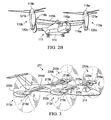
Figure 2A is a plan view of a tilt rotor aircraft according to the present application in an airplane mode; -
Figure 2B is a perspective view of a tilt rotor aircraft according to the present application in a helicopter mode; -
Figure 3 is a perspective view of a quad tilt rotor aircraft according to the present application in an airplane mode; -
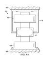
Figure 4A is a front view of a vibration isolator according to the present application; -
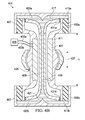
Figure 4B is a partial cross-sectional view of the vibration isolator ofFigure 4A ; -
Figure 4C is a mechanical equivalent model for the tunable vibration isolator according to the vibration isolation ofFigure 4A ; -
Figure 5 is a cross-sectional view of a vibration isolator according to an alternative embodiment of the present application; -
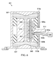
Figure 6 is a cross-sectional view of a vibration isolator according to an alternative embodiment of the present application; -
Figure 7 is a cross-sectional view of a vibration isolator according to an alternative embodiment of the present application; and -
Figure 8 is a perspective view of an embodiment of a linear inductance motor assembly from the vibration isolator ofFigure 7 , according to the present application. - While the system of the present application is susceptible to various modifications and alternative forms, specific embodiments thereof have been shown by way of example in the drawings and are herein described in detail. It should be understood, however, that the description herein of specific embodiments is not intended to limit the method to the particular forms disclosed, but on the contrary, the intention is to cover all modifications, equivalents, and alternatives falling within the spirit and scope of the application as defined by the appended claims.
- Referring to
Figure 1 in the drawings, ahelicopter 11 according to the present application is illustrated.Helicopter 11 has afuselage 13 and amain rotor assembly 15, includingmain rotor blades 17 and amain rotor mast 18.Helicopter 11 has atail rotor assembly 19, includingtail rotor blades 21 and atail rotor mast 20.Main rotor blades 17 generally rotate about a vertical axis 16 ofmain rotor mast 18.Tail rotor blades 21 generally rotate about alateral axis 22 oftail rotor mast 20.Helicopter 11 also includes a vibration isolation system according to the present application for isolatingfuselage 13 or other portions ofhelicopter 11 from mechanical vibrations, such as harmonic vibrations, which are associated with the propulsion system and which arise from the engine, transmission, and rotors ofhelicopter 11. - The vibration isolation system of the present application may also be utilized on other types of rotary wing aircraft. Referring now to
Figures 2A and2B in the drawings, atilt rotor aircraft 111 according to the present application is illustrated. As is conventional with tilt rotor aircraft,rotor assemblies wings end portions wings Tilt rotor assemblies nacelles tilt rotor aircraft 111, as well as,rotor hubs tilt rotor assemblies -
Tilt rotor assemblies wing members rotor assemblies tilt rotor aircraft 111 flies like a conventional helicopter; and an airplane mode in which tiltrotor assemblies tilt rotor aircraft 111 flies like a conventional propeller driven aircraft. InFigure 2A ,tilt rotor aircraft 111 is shown in the airplane mode; and inFigure 2B ,tilt rotor aircraft 111 is shown in the helicopter mode. As shown inFigures 2A and2B ,wings fuselage 114.Tilt rotor aircraft 111 also includes a vibration isolation system according to the present application for isolatingfuselage 114 or other portions oftilt rotor aircraft 111 from mechanical vibrations, such as harmonic vibrations, which are associated with the propulsion system and which arise from the engines, transmissions, and rotors oftilt rotor aircraft 111. - Referring now to
Figure 3 in the drawings, a quadtilt rotor aircraft 211 according to the present application is illustrated. As with thetilt rotor aircraft 111 ofFigures 2A and2B ,rotor assemblies forward wing aft wing Tilt rotor assemblies nacelles tilt rotor aircraft 211, as well as,rotor hubs tilt rotor assemblies -
Tilt rotor assemblies wing members rotor assemblies tilt rotor aircraft 211 flies like a conventional helicopter; and an airplane mode in which tiltrotor assemblies tilt rotor aircraft 211 flies like a conventional propeller driven aircraft. InFigure 3 , quadtilt rotor aircraft 111 is shown in the airplane mode. As shown inFigure 3 ,wings fuselage 214.Tilt rotor aircraft 211 also includes a vibration isolation system according to the present application for isolatingfuselage 214 or other portions of quadtilt rotor aircraft 211 from mechanical vibrations, such as harmonic vibrations, which are associated with the propulsion system and which arise from the engines, transmissions, and rotors of quadtilt rotor aircraft 211. It should be understood that the present application may be used with any aircraft on which it would be desirable to have vibration isolation according to the present application, including unmanned aerial vehicles that are remotely piloted. - Referring now to
Figure 4A in the drawings, avibration isolator 401 for use on an aircraft is illustrated.Isolator 401 includes a generallycylindrical housing 407. In the illustrated embodiment,housing 407 is rigidly divided between an upper housing and a lower housing. Apiston 411 of selected cross-sectional diameter is disposed within the interior ofhousing 407.Housing 407 is typically coupled to afuselage 405 of an aircraft andpiston 411 is typically coupled to the transmission and propulsion system of the aircraft (not shown) via apylon assembly 403 at anattachment bracket 415. In such an arrangement,fuselage 405 serves as the body to be isolated from vibration, andpylon assembly 403 of the aircraft serves as the vibrating body. - Referring now also to
Figure 4B ,vibration isolator 401 is illustrated in a cross section view. Anupper fluid chamber 413a is partially defined by the interior of an upper portion ofhousing 407. Alower fluid chamber 413b is partially defined by the interior of a lower portion ofhousing 407.Piston 411 is resiliently located against the upper and lower portions ofhousing 407 withelastomer members passage 419 extends centrally throughpiston 411 and permits a vibration-isolation fluid 417 to move between upperfluid chamber 413a andlower fluid chamber 413b, through tuningpassage 419. The approximate length of tuningpassage 419 is defined by T1 inFigure 4B . Aconical flow diverter 421 is provided at each end ofupper fluid chamber 413a andlower fluid chamber 413b and is aligned with and generally opposes the opening at each end of tuningpassage 419. Eachconical flow diverter 421 enhances fluid flow by decelerating the vibration-isolation fluid as it flows from each end of the fluid chamber into and out of tuningpassage 419. - A linear
induction motor assembly 425 includes amagnet member 429 andinductance coils 427.Magnet member 429 is generally cylindrical with an interior surface formingtuning passage 419.Magnet member 429 is in contact at each end with anupper pumper piston 423a and alower pumper piston 423b.Upper pumper piston 423a andlower pumper piston 423b are each cone shaped, the larger circular end being coupled topiston 411 withpumper elastomer members upper pumper piston 423a andlower pumper piston 423b being in contact withmagnet member 429. - Vibration-
isolation fluid 417, also referred to as tuning fluid, is preferably a high-density, low-viscosity fluid disposed within tuningpassage 419 andfluid chambers isolation fluid 417 influid chambers elastomer members piston 411 to move or oscillate relative tohousing 407, while maintainingpiston 411 in a central location inhousing 407 when no load is applied. - During operation of
vibration isolator 401,elastomer members piston 411 to move or oscillate relative tohousing 407. The introduction of a force intopiston bracket 415 displacespiston 411 relative tohousing 407 in adirection 437. Because the force and displacement is oscillatory over time,piston 411 similarly oscillates relative tohousing 407. Each oscillatory displacement ofpiston 411 relative tohousing 407 similarly causes a displacement ofupper pumper piston 423a andlower pumper piston 423b. A displacement ofupper pumper piston 423a andlower pumper piston 423b in a first direction causes a displacement of tuning fluid through tuningpassage 419 in the opposite direction of the displacement ofpiston 411. The displacement ofpiston 411 causes an oscillatory reaction force due to strain inelastomer members isolation fluid 417 influid chambers isolation fluid 417 is pumped back and forth throughtuning passage 419. The inertial force created by acceleration of the mass of the vibration-isolation fluid 417 is out of phase of the force introduced topiston 411 viabracket 415. At an isolation frequency, the force of the mass of the vibration-isolation fluid 417 cancels the force introduced topiston 411 viabracket 415. In some embodiments, a small amount of undesirable damping can occur at the isolation frequency; thereby preventing complete force cancellation from occurring, as such, a small amount of vibratory force can sometimes be transferred from vibratingbody 403 toisolated body 405. - A passive isolation frequency of
isolator 401 is in part, a function of the ratio of the effective piston area ofupper pumper piston 423a andlower pumper piston 423b, to the diameter of tuningpassage 419. As such, theisolator 401 is sized so the isolation frequency cancels the predicted vibratory frequency of vibratingbody 403. When the source of vibration in vibratingbody 403 is a rotor system of an aircraft, the vibratory frequency is typically the n/revolution frequency, where n is the number of rotor blades rotating around a mast axis of rotation at a certain rotational speed. However, some rotorcraft may be variable RPM rotorcraft, in that the rotorcraft can have the ability to operate in a range of rotor RPM's. Further, other factors, such as temperature, aging of elastomer members, tolerance variations, to name a few, make it desirable to actively change the isolation frequency ofisolator 401. -
Isolator 401 is configured to actively change the isolation frequency with linearinductance motor assembly 425.Control system 435 is electrically coupled viaelectrical leads inductance coils 427 for selectively providing oscillatory forces toupper pumper piston 423a andlower pumper piston 423b, viamagnet 429. More specifically, linearinductance motor assembly 425 can actively adjust the isolation frequency ofisolator 401 by modifying the acceleration of the vibration-isolation fluid 417, thereby modifying the inertial force of the vibration-isolation fluid 417 as it is accelerated back and forth throughtuning passage 419.Control system 435 is configured to select the frequencies and the oscillatory forces imparted onupper pumper piston 423a andlower pumper piston 423b, viamagnet 429. In this manner, the oscillatory vibrations from the vibratingbody 403 are prevented from transferring to isolated body, even when the vibratory frequency ofvibratory body 403 changes. Further, linearinductance motor assembly 425 can be operated to deepen the isolation frequency to negate any dampening losses. - The isolation frequency (fi ) of
vibration isolator 401 is can be represented by the following equation:
- In the above equation, R represents the ratio of the effective cross sectional area of
upper pumper piston 423a andlower pumper piston 423b, to the cross sectional area of tuningpassage 419. Mass of tuningfluid 417 is represented by mt . The spring rate ofelastomer members - Referring now to
Figure 4C in the drawings, a mechanicalequivalent model 439 for the tunable vibration isolator according to the present application is illustrated. The tunable vibration isolator of the present application is preferably used to isolate the vibration generated by the transmission and propulsion system of an aircraft, such asaircraft fuselages Figures 1-3 ). However, it should be understood that although the tunable vibration isolator of the present application is described herein with respect to an aircraft application, it may be used in any application in which it is desirable to isolate the vibration between one body and another. The following discussion of the preferred embodiment of the present application will be with respect to an application of the tunable vibration isolator on a rotorcraft aircraft 11 (seeFigure 1 ) to isolate the vibratory forces generated in a pylon from a fuselage. - In mechanical
equivalent model 439, the fuselage is represented as the mass of the fuselage Mfuselage, orbox 405; the pylon is represented as the mass of the pylon Mpylon, orbox 403; and abox 441 represents the mass of the tuning mass Mt, which in the present embodiment can be vibration-isolation fluid disposed in the isolator. A vibratory force F·sin(ωt) is generated by the propulsion system. - Force F·sin(ωt) causes an oscillatory displacement up of the pylon Mpylon; an oscillatory displacement ufuselage of the fuselage Mfuselage; and an oscillatory displacement utuning mass of the tuning mass Mt. A spring member, represented by a
spring - Tuning mass Mt is operably associated with fuselage Mfuselage and pylon Mpylon. In mechanical
equivalent model 439, tuning mass Mt functions as if cantilevered from afirst fulcrum 443 attached to pylon member Mpylon, and asecond fulcrum 445 attached to the fuselage Mfuselage. The distance a fromfirst fulcrum 443 tosecond fulcrum 445 represents the cross-sectional area of the tuning passage, and the distance b fromfirst fulcrum 443 to the tuning mass Mt represents the effective cross-sectional area of a piston (see 423a and 423b inFigure 4B ), such that an area ratio, or hydraulic ratio, R is equal to the ratio of b to a. - An
active tuning element 425 is disposed between the pylon Mpylon and the tuning mass Mt.Active tuning element 425 functions to makefulcrum 443 vibrate. It should be understood thatactive tuning element 425 may represent a plurality of active tuning elements acting either together or independently. In the preferred embodiment, active tuning element is a linear inductance motor assembly. -
Active tuning element 425 can be represented by mechanical properties include aspring element controllable force element 429.Controllable force element 429 may have any phase angle and be of any magnitude within the maximum capabilities ofactive tuning element 425.Active tuning element 425 also includes control circuitry for controlling the actuation ofactive tuning element 429.Active tuning element 425 allows for selective actuation of the tuning mass. Mechanicalequivalent model 439 leads to the following equation of motion for the system:
- Referring now also to
Figure 5 , avibration isolator 501 is an alternative embodiment ofvibration isolator 401.Vibration isolator 501 is substantially similar tovibration isolator 401. Anupper fluid chamber 513a is partially defined by the interior of an upper portion ofhousing 507. Alower fluid chamber 513b is partially defined by the interior of a lower portion ofhousing 507.Piston 511 is resiliently located againsthousing 507 withelastomer members passage 519 extends centrally throughpiston 511 and permits a vibration-isolation fluid 517 to move between upperfluid chamber 513a andlower fluid chamber 513b, through tuningpassage 519. The approximate length of tuningpassage 519 is defined by T1 inFigure 5 . A linearinduction motor assembly 525 includes amagnet member 529 andinductance coils 527.Magnet member 529 is generally cylindrical with an interior surface at least partially formingtuning passage 519.Magnet member 529 preferable has curved end portions that contribute to the pumping offluid 517 betweenfluid chambers Magnet member 529 is slidingly coupled topiston 511 such that a magnetic force generated byinductance coil 527 causesmagnet member 529 to slide or otherwise translate relative topiston 511. The end portions ofmagnet member 529 act like a piston when slidingly displaced relative topiston 511, so as to accelerate tuning fluid 517 through tuningpassage 519, in the opposite direction of the displacement ofmagnet 529. - Vibration-
isolation fluid 517, also referred to as tuning fluid, is preferably a high-density, low-viscosity fluid disposed within tuningpassage 519 andfluid chambers isolation fluid 517 influid chambers elastomer members piston 511 to move or oscillate relative tohousing 507, while maintainingpiston 511 in a central location inhousing 507 when no load is applied. - During operation of
vibration isolator 501,elastomer members piston 511 to move or oscillate relative tohousing 507. The introduction of a force into piston bracket 415 (shown inFigure 4A ) displacespiston 511 relative tohousing 507 in adirection 537. Because the force and displacement is oscillatory over time,piston 511 similarly oscillates relative tohousing 507. A displacement ofpiston 511 in a first direction causes adisplacement tuning fluid 517 through tuningpassage 519 in the opposite direction of the displacement ofpiston 511. The displacement ofpiston 511 causes an oscillatory reaction force due to strain inelastomer members isolation fluid 517 influid chambers isolation fluid 517 is pumped back and forth throughtuning passage 519. The inertial force created by acceleration of the mass of the vibration-isolation fluid 517 is out of phase of the force introduced topiston 511 via bracket 415 (shown inFigure 4A ). At an isolation frequency, the force of the mass of the vibration-isolation fluid 517 cancels the force introduced topiston 511 via bracket 415 (shown inFigure 4A ). In some embodiments, a small amount of damping can occur at the isolation frequency; thereby preventing complete force cancellation from occurring, as such, a small amount of vibratory force can sometimes be transferred from vibrating body 403 (shown inFigure 4A ) to isolated body 405 (shown inFigure 4A ). - A passive isolation frequency of
isolator 501 is in part, a function of the ratio of the effective piston area ofpiston 511. In the illustrated embodiment, the end portions ofmagnet 529 also contribute to the effective piston area. As such, theisolator 501 is sized so the isolation frequency cancels the predicted vibratory frequency of vibratingbody 403. When the source of vibration in vibratingbody 403 is a rotor system of an aircraft, the vibratory frequency is typically the n/revolution frequency, where n is the number of rotor blades rotating around a mast axis of rotation at a certain speed. However, some rotorcraft may be variable RPM rotorcraft, in that the rotorcraft can have the ability to operate in a range of rotor RPM's. Further, other factors, such as temperature, aging of elastomer members, tolerance variations, to name a few, make it desirable to actively change the isolation frequency ofisolator 501. -
Isolator 501 is configured to actively change the isolation frequency with linearinductance motor assembly 525.Control system 535 is electrically coupled viaelectrical leads inductance coils 527 for selectively providing oscillatory forces to tuningfluid 517, viamagnet 529. More specifically, linearinductance motor assembly 525 can actively adjust the isolation frequency ofisolator 501 by modifying the acceleration of the vibration-isolation fluid 517, thereby modifying the inertial force of the vibration-isolation fluid 517 as it is accelerated back and forth throughtuning passage 519.Control system 535 is configured to select the frequencies and of the oscillatory forces imparted on tuningfluid 517, viamagnet 529. In this manner, the oscillatory vibrations from the vibratingbody 403 are prevented from transferring to the isolated body, even when the vibratory frequency ofvibratory body 403 changes. Further, linearinductance motor assembly 525 can be operated to deepen the isolation frequency to negate any dampening losses. - Referring now also to
Figure 6 , anisolator 601 is a substantial similar alternative embodiment ofisolator 501. Further, the discussion herein with regard toisolator 501 substantially applies toisolator 601. However,isolator 601 includes a linearinductance motor assembly 625 having amagnet 629 andinductance coils 627 that are integrated into the interior of the body ofpiston 511.Magnet 629 is selectively actuated byinductance coils 627.Magnet 629 is configured as a piston, and is located in aninternal piston passage 643, such that actuation ofmagnet 629 pumps tuning fluid 517 between upper andlower fluid chambers magnet 629 changes the isolation frequency ofisolator 601. - Referring now also to
Figure 7 , anisolator 701 is a substantial similar alternative embodiment ofisolators isolators isolator 701. However,isolator 701 includes a linearinductance motor assembly 725 having amagnet 729 andinductance coils 727 that are located in anexternal housing 745.Magnet 729 is selectively actuated byinductance coils 727.Magnet 729 is configured as a piston such that actuation ofmagnet 729 pumps tuning fluid 517 between upper andlower fluid chambers ports Magnet 729 can havepiston end portions 749a and 749 that are of a material that is non-magnetic. Selective actuation ofmagnet 729 changes the isolation frequency ofisolator 701, by changing the internal mass of tuning fluid 517 traveling through tuningpassage 519. - Referring now also to
Figure 8 , a portion of an embodiment of linearinductance motor assembly 725, fromisolator 701, is illustrated in further detail. As shown inFigure 8 , linearinductance motor assembly 725 can include abaffle 751 that housesmagnet 729 andinductance coils 727.Baffle 751 is preferable of a metallic material, but may be any material capable of resisting fatigue.Baffle 751 is preferable coupled to each end ofpiston portion Baffle 751 is configured to protectmagnet 729 andinductance coil 727 from tuningfluid 517. - It is apparent that a system with significant advantages has been described and illustrated. Although the present application is shown in a limited number of forms, it is not limited to just these forms, but is amenable to various changes and modifications without departing from the spirit thereof.
Claims (18)
- A vibration isolator, comprising:a housing having an upper fluid chamber and a lower fluid chamber;a tuning passage;a tuning fluid disposed within the tuning passage, the upper fluid chamber, and the lower fluid chamber;a primary piston resiliently disposed within the housing;an upper pumper piston and a lower pumper piston, the upper pumper piston and the lower pumper piston being coupled to the primary piston;a linear inductance motor assembly comprising:a magnet member coupled between the upper pumper piston and the lower pumper piston;an inductance coil at least partially surrounding the magnet member; anda control system configured to selectively actuate the magnet member, wherein selective actuation of the magnet member selectively imparts a force upon the upper pumper piston and the lower pumper piston.
- A vibration isolator, comprising:a housing having an upper fluid chamber and a lower fluid chamber;a tuning passage;a tuning fluid disposed within the tuning passage, the upper fluid chamber, and the lower fluid chamber;a piston resiliently disposed within the housing;a linear inductance motor assembly comprising:a magnet member configured to translate relative to the piston;an inductance coil at least partially surrounding the magnet member; anda control system configured to selectively actuate the magnet member; wherein selective actuation of the magnet member selectively imparts a pumping force on the tuning fluid.
- A vibration isolator, comprising:a first housing having an upper fluid chamber and a lower fluid chamber;a tuning passage;a tuning fluid disposed within the tuning passage, the upper fluid chamber, and the lower fluid chamber;a piston resiliently disposed within the first housing;a second housing having a first port in fluid communication with the upper fluid chamber, and a second port in fluid communication with the lower fluid chamber;a linear inductance motor assembly located in the second housing, the linear inductance motor assembly comprising:a magnet member configured to translate relative to the second housing;an inductance coil at least partially surrounding the magnet member; anda control system configured to selectively actuate the magnet member; wherein selective actuation of the magnet member selectively imparts a pumping force on the tuning fluid.
- The vibration isolator according to claim 1, wherein the upper pumper piston and the lower pumper piston are each coupled to the primary piston with at least one elastomer member.
- The vibration isolator according to claim 1 or claim 4, wherein the upper pumper piston and the lower pumper piston are each conical shaped.
- The vibration isolator according to claim 1 or any preceding claim, wherein the inductance coil is configured to translate the magnet relative to the inductance coil.
- The vibration isolator according to claim 1 or any of claims 4 to 6, wherein the linear inductance motor assembly is configured to selectively contribute to the amount of volume of the tuning fluid pumped through the tuning passage during an actuation of the primary piston.
- The vibration isolator according to claim 1 or any of claims 4 to 7, wherein the inductance coil is partially embedded in the primary piston.
- The vibration isolator according to claim 1 or any of claims 4 to 8, wherein a length of the tuning passage is defined by the magnet.
- The vibration isolator according to claim 2, or any preceding claim, wherein the magnet member has end portions that form a piston, such that a displacement of the magnet member relative to the piston acts to accelerate the tuning fluid in the opposite direction of the displacement of the magnet member.
- The vibration isolator according to claim 2 or any preceding claim, wherein the magnet member is configured to slidingly translate relative to the piston.
- The vibration isolator according to claim 2 or any preceding claim, wherein the linear inductance motor assembly is configured to selectively contribute to the amount of volume of the tuning fluid pumped through the tuning passage during an actuation of the piston.
- The vibration isolator according to claim 2, or claim 3 or any peceding claim dependent directly or indirectly from claim 2 or claim 3, wherein the inductance coil is at least partially embedded in the piston.
- The vibration isolator according to claim 2 or any preceding claim, wherein the tuning passage is at least partially defined by the magnet.
- The vibration isolator according to claim 2, or claim 3 or any preceding claim dependent directly or indirectly from claim 2 or claim 3,, wherein the magnet member is located in an internal piston passage, the internal piston passage being a port located through the piston, internal piston passage being separate from the tuning passage, and optionally or preferably wherein the inductance coil at least partially surrounds the internal piston passage.
- The vibration isolator according to claim 3 or any preceding claim, wherein the magnet member is coupled to a piston portion, such that a displacement of the magnet member relative to the piston acts to translate the piston portion so as accelerate the tuning fluid through the tuning passage.
- The vibration isolator according to claim 3 or any preceding claim, wherein the magnet member is configured to slidingly translate relative to the inductance coil.
- The vibration isolator according to claim 3 or any preceding claim, wherein the magnet member and the inductance coil are located in a baffle.
Applications Claiming Priority (1)
| Application Number | Priority Date | Filing Date | Title |
|---|---|---|---|
| US13/294,230 US8882091B2 (en) | 2011-11-11 | 2011-11-11 | Vibration isolation system |
Publications (2)
| Publication Number | Publication Date |
|---|---|
| EP2592300A1 true EP2592300A1 (en) | 2013-05-15 |
| EP2592300B1 EP2592300B1 (en) | 2014-02-12 |
Family
ID=45400988
Family Applications (1)
| Application Number | Title | Priority Date | Filing Date |
|---|---|---|---|
| EP20110195436 Active EP2592300B1 (en) | 2011-11-11 | 2011-12-22 | Vibration isolation system |
Country Status (4)
| Country | Link |
|---|---|
| US (1) | US8882091B2 (en) |
| EP (1) | EP2592300B1 (en) |
| CN (1) | CN103104651B (en) |
| CA (1) | CA2789472C (en) |
Families Citing this family (17)
| Publication number | Priority date | Publication date | Assignee | Title |
|---|---|---|---|---|
| US8731743B2 (en) * | 2012-04-11 | 2014-05-20 | Textron Innovations Inc. | Self tuning vibration isolation system |
| CN102734379B (en) * | 2012-06-09 | 2013-12-11 | 哈尔滨工业大学 | Active vibration isolating device based on composite support of electromagnetism and static-pressure air floatation |
| US9303709B2 (en) | 2014-08-11 | 2016-04-05 | Ggodrich Corporation | Shock damper |
| US10012217B2 (en) * | 2015-05-20 | 2018-07-03 | Bell Helicopter Textron Inc. | Controlled pump augmentation for active vibration isolation |
| WO2017147781A1 (en) * | 2016-03-01 | 2017-09-08 | 深圳市大疆创新科技有限公司 | Storage medium, unmanned aircraft, and shaking detection and tracking control method and system |
| CN107148383B (en) * | 2016-05-31 | 2019-03-08 | 深圳市大疆创新科技有限公司 | Unmanned aerial vehicle rack and unmanned aerial vehicle |
| CN106377903B (en) * | 2016-10-12 | 2018-12-21 | 徐州惠博机电科技有限公司 | A kind of brain sensing unmanned aerial vehicle |
| CN106364671B (en) * | 2016-10-12 | 2019-01-25 | 江苏锦程航空科技有限公司 | an unmanned micro air vehicle |
| US10301010B2 (en) | 2016-10-20 | 2019-05-28 | Bell Helicopter Textron Inc. | Oscillating pump systems for use on aircraft |
| US20180265186A1 (en) | 2017-03-15 | 2018-09-20 | Bell Helicopter Textron Inc. | Vibration Isolation Systems for Advancing Blade Concept Rotorcraft |
| US11932380B2 (en) | 2017-03-15 | 2024-03-19 | Textron Innovations Inc. | Vibration isolation systems for compound helicopters |
| CN107839871B (en) * | 2017-11-30 | 2023-11-17 | 歌尔股份有限公司 | Propeller connection structure and unmanned vehicles |
| DE102018208186B4 (en) * | 2018-05-24 | 2021-07-22 | Contitech Vibration Control Gmbh | Linear actuator, preferably for an active hydraulic motor mount |
| EP3750801B1 (en) * | 2019-06-13 | 2021-08-04 | LEONARDO S.p.A. | Rotor for a hover-capable aircraft |
| US11440648B2 (en) | 2020-04-22 | 2022-09-13 | Textron Innovations Inc. | Compact vibration isolation systems for aircraft |
| CN112093063B (en) * | 2020-09-18 | 2024-05-28 | 星展测控科技股份有限公司 | Helicopter external equipment mounting rack |
| CN120159888B (en) * | 2025-04-21 | 2025-11-21 | 西北工业大学 | An adjustable frequency liquid-elastic vibration isolator and its frequency adjustment method |
Citations (7)
| Publication number | Priority date | Publication date | Assignee | Title |
|---|---|---|---|---|
| US4236607A (en) | 1979-02-26 | 1980-12-02 | Textron, Inc. | Vibration suppression system |
| US5435531A (en) | 1993-08-18 | 1995-07-25 | Bell Helicopter Textron Inc. | Vibration isolation system |
| US5439082A (en) | 1994-04-01 | 1995-08-08 | Bell Helicopter Textron Inc. | Hydraulic inertial vibration isolator |
| US5704596A (en) | 1993-08-18 | 1998-01-06 | Bell Helicopter | Vibration isolation system |
| US6009983A (en) | 1997-05-30 | 2000-01-04 | Bell Helicopter Textron, Inc. | Method and apparatus for improved vibration isolation |
| US6695106B2 (en) | 2000-09-26 | 2004-02-24 | Bell Helicopter Textron, Inc. | Method and apparatus for improved vibration isolation |
| US20060151272A1 (en) * | 2002-09-24 | 2006-07-13 | Smith Michael R | Piezoelectric liquid inertia vibration eliminator |
Family Cites Families (49)
| Publication number | Priority date | Publication date | Assignee | Title |
|---|---|---|---|---|
| US2819131A (en) | 1955-05-09 | 1958-01-07 | Francis M Lankford | Slush pump pistons |
| US2964272A (en) | 1955-07-01 | 1960-12-13 | Rca Corp | Vibration control apparatus |
| US3088062A (en) | 1956-02-10 | 1963-04-30 | Albert A Hudimac | Electromechanical vibratory force suppressor and indicator |
| US4452437A (en) | 1981-04-20 | 1984-06-05 | Kaspar Lochner | Hydraulic-operating shock and vibration absorber and damper |
| JPH0646058B2 (en) | 1982-04-19 | 1994-06-15 | チャプリン パテンツ ホ−ルディング カンパニ− インコ−ポレ−テッド | Device for damping vibration transmission from a vibration source to a support structure |
| US4629039A (en) | 1985-01-17 | 1986-12-16 | Nippondenso Co., Ltd | Vehicle braking control apparatus |
| JPS61171686A (en) | 1985-01-24 | 1986-08-02 | Mitsubishi Heavy Ind Ltd | Vibration damping type ship superstructure |
| JPS61224878A (en) | 1985-03-29 | 1986-10-06 | Canon Inc | vibration wave motor |
| US4725019A (en) | 1986-08-11 | 1988-02-16 | The Boeing Company | Aircraft engine mount with vertical vibration isolation |
| WO1988005506A1 (en) | 1987-01-16 | 1988-07-28 | Topexpress Limited | Active control of vibration |
| GB8710998D0 (en) | 1987-05-08 | 1987-06-10 | Btr Plc | Vehicle engine suspension systems |
| GB8816188D0 (en) | 1988-07-07 | 1988-11-16 | Marconi Gec Ltd | Mounting for machinery |
| US5067684A (en) | 1988-12-22 | 1991-11-26 | Moog Inc. | Vibration-isolating machine mount |
| DE3908577A1 (en) | 1989-03-16 | 1990-09-20 | Laukien Guenther | METHOD AND DEVICE FOR REDUCING THE SOUND EMISSION OF SUBMERSIBLES SUBMERSIBLE |
| US5423523A (en) | 1990-04-09 | 1995-06-13 | Noise Cancellation Technologies, Inc. | Integrated hydraulic mount for active vibration control system |
| DE4116270C2 (en) | 1990-05-18 | 2002-01-17 | Toyo Tire & Rubber Co | attenuator |
| CA2072326A1 (en) | 1991-08-08 | 1993-02-09 | Charles D. Iacovangelo | Method for selective cvd diamond deposition |
| US5265552A (en) | 1991-09-20 | 1993-11-30 | Taylor Devices, Inc. | Shock and vibration isolator for member mounted on submerged body |
| US5174552A (en) | 1991-10-15 | 1992-12-29 | Lord Corporation | Fluid mount with active vibration control |
| JP2546465B2 (en) | 1992-01-28 | 1996-10-23 | 鹿島建設株式会社 | Vibration control device for structures |
| FR2689951B1 (en) | 1992-04-10 | 1995-08-18 | Bertin & Cie | RIGID MECHANICAL CONNECTION DEVICE WITH FREQUENCY CUT. |
| CA2094208A1 (en) | 1992-04-28 | 1993-10-29 | Richard D. Hein | Prepackaged fluid-damping article for elastomeric mounts and methods of formation and installation |
| FR2703121B1 (en) | 1993-03-25 | 1995-06-23 | Bertin & Cie | Anti-vibration device for supporting a vibrating mass. |
| DE4340034C1 (en) | 1993-11-24 | 1995-02-02 | Freudenberg Carl Fa | Mounting arrangement |
| DE4407962C1 (en) | 1994-03-10 | 1995-06-01 | Continental Ag | Setting or drive element using electro- or magneto-strictive actuator |
| DE69514246T2 (en) | 1994-10-12 | 2000-05-31 | Lord Corp., Cary | ACTIVE SYSTEMS AND DEVICES INCLUDING ACTIVE VIBRATION DAMPERS |
| JP3545415B2 (en) | 1994-12-01 | 2004-07-21 | ベル ヘリコプター テクストロン インコーポレイティド | Vibration isolator |
| CA2485830C (en) | 1994-12-01 | 2007-02-06 | Bell Helicopter Textron Inc. | Vibration isolation system |
| US5458222A (en) | 1994-12-05 | 1995-10-17 | General Electric Company | Active vibration control of structures undergoing bending vibrations |
| FR2731405B1 (en) | 1995-03-10 | 1997-05-09 | Eurocopter France | SYSTEM FOR MINIMIZING DYNAMIC EXCITATION OF A HELICOPTER |
| DE19532039A1 (en) | 1995-08-31 | 1997-03-06 | Porsche Ag | Device for damping body vibrations |
| GB2311502B (en) | 1996-03-08 | 2000-06-14 | Marconi Gec Ltd | Mounting of machinery within a vessel |
| US5788372A (en) | 1996-05-10 | 1998-08-04 | Lord Corporation | Method and apparatus for reducing transient motion between an aircraft power member and structure during takeoff, landing and maneuvers |
| US5803213A (en) | 1997-02-03 | 1998-09-08 | Honeywell Inc. | Heavy load vibration isolation apparatus |
| US6129306A (en) | 1997-03-05 | 2000-10-10 | Pham; Roger N. C. | Easily-convertible high-performance roadable aircraft |
| US5957440A (en) | 1997-04-08 | 1999-09-28 | Lord Corporation | Active fluid mounting |
| US5947457A (en) | 1997-04-08 | 1999-09-07 | Lord Corporation | Fluid-filled active vibration absorber |
| US6032936A (en) | 1997-08-04 | 2000-03-07 | Lord Corporation | Fluid mount including a partitionless compensator |
| US6293532B2 (en) | 1997-08-04 | 2001-09-25 | Lord Corporation | Fluid and elastomer apparatus |
| US6394432B1 (en) | 1998-06-10 | 2002-05-28 | Lord Corporation | Vibration and/or shock absorbing devices and compensator elements utilized therein |
| DE19832697C2 (en) | 1998-07-21 | 2000-11-16 | Eurocopter Deutschland | Device and method for reducing vibrations along a vibration propagation, in particular in a helicopter |
| US6123312A (en) | 1998-11-16 | 2000-09-26 | Dai; Yuzhong | Proactive shock absorption and vibration isolation |
| GB2358900A (en) | 2000-02-01 | 2001-08-08 | Draftex Ind Ltd | Vibration damping |
| GB0004649D0 (en) | 2000-02-29 | 2000-04-19 | Gkn Westland Helicopters Ltd | Vibration damping apparatus |
| US6389941B1 (en) | 2000-04-14 | 2002-05-21 | Marquip, Llc | Rotary knife with electromagnetic active vibration control |
| GB2361757B (en) | 2000-04-28 | 2003-12-03 | Bae Sys Electronics Ltd | Improvements in or relating to the damping of vibration |
| DE60134767D1 (en) | 2000-09-26 | 2008-08-21 | Bell Helicopter Textron Inc | UNGSISOLIERUNG |
| US6340153B1 (en) | 2000-11-02 | 2002-01-22 | General Dynamics Advanced Technology Systems, Inc. | Shock and acoustic mount |
| CA2489103C (en) | 2002-06-07 | 2009-03-31 | Boart Longyear Limited | Vibration isolator |
-
2011
- 2011-11-11 US US13/294,230 patent/US8882091B2/en active Active
- 2011-12-22 EP EP20110195436 patent/EP2592300B1/en active Active
-
2012
- 2012-09-07 CA CA2789472A patent/CA2789472C/en active Active
- 2012-10-12 CN CN201210385846.2A patent/CN103104651B/en not_active Expired - Fee Related
Patent Citations (7)
| Publication number | Priority date | Publication date | Assignee | Title |
|---|---|---|---|---|
| US4236607A (en) | 1979-02-26 | 1980-12-02 | Textron, Inc. | Vibration suppression system |
| US5435531A (en) | 1993-08-18 | 1995-07-25 | Bell Helicopter Textron Inc. | Vibration isolation system |
| US5704596A (en) | 1993-08-18 | 1998-01-06 | Bell Helicopter | Vibration isolation system |
| US5439082A (en) | 1994-04-01 | 1995-08-08 | Bell Helicopter Textron Inc. | Hydraulic inertial vibration isolator |
| US6009983A (en) | 1997-05-30 | 2000-01-04 | Bell Helicopter Textron, Inc. | Method and apparatus for improved vibration isolation |
| US6695106B2 (en) | 2000-09-26 | 2004-02-24 | Bell Helicopter Textron, Inc. | Method and apparatus for improved vibration isolation |
| US20060151272A1 (en) * | 2002-09-24 | 2006-07-13 | Smith Michael R | Piezoelectric liquid inertia vibration eliminator |
Also Published As
| Publication number | Publication date |
|---|---|
| CA2789472A1 (en) | 2013-05-11 |
| CA2789472C (en) | 2015-03-24 |
| US8882091B2 (en) | 2014-11-11 |
| CN103104651B (en) | 2014-12-03 |
| US20130119591A1 (en) | 2013-05-16 |
| CN103104651A (en) | 2013-05-15 |
| EP2592300B1 (en) | 2014-02-12 |
Similar Documents
| Publication | Publication Date | Title |
|---|---|---|
| EP2592300B1 (en) | Vibration isolation system | |
| EP2615027B1 (en) | A mechanically optimized liquid inertia vibration eliminator and aircraft pylon system | |
| EP2406518B1 (en) | Method and apparatus for improved vibration isolation | |
| US9446841B2 (en) | Method and apparatus for improved vibration isolation | |
| EP2182239A2 (en) | Piezoelectric liquid inertia vibration eliminator | |
| WO2002027210A1 (en) | Method and apparatus for improved vibration isolation | |
| US8602400B2 (en) | Method and apparatus for improved vibration isolation | |
| CA2665700C (en) | Vibration-attenuating hard-mounted pylon | |
| US9249856B1 (en) | Liquid inertia vibration mount | |
| EP2610172B1 (en) | System and method of tuning a liquid inertia vibration eliminator | |
| EP1334289B1 (en) | Method and apparatus for improved vibration isolation | |
| US20240025538A1 (en) | Live system with splash guard |
Legal Events
| Date | Code | Title | Description |
|---|---|---|---|
| PUAI | Public reference made under article 153(3) epc to a published international application that has entered the european phase |
Free format text: ORIGINAL CODE: 0009012 |
|
| 17P | Request for examination filed |
Effective date: 20111222 |
|
| AK | Designated contracting states |
Kind code of ref document: A1 Designated state(s): AL AT BE BG CH CY CZ DE DK EE ES FI FR GB GR HR HU IE IS IT LI LT LU LV MC MK MT NL NO PL PT RO RS SE SI SK SM TR |
|
| AX | Request for extension of the european patent |
Extension state: BA ME |
|
| GRAP | Despatch of communication of intention to grant a patent |
Free format text: ORIGINAL CODE: EPIDOSNIGR1 |
|
| INTG | Intention to grant announced |
Effective date: 20131018 |
|
| GRAS | Grant fee paid |
Free format text: ORIGINAL CODE: EPIDOSNIGR3 |
|
| GRAA | (expected) grant |
Free format text: ORIGINAL CODE: 0009210 |
|
| AK | Designated contracting states |
Kind code of ref document: B1 Designated state(s): AL AT BE BG CH CY CZ DE DK EE ES FI FR GB GR HR HU IE IS IT LI LT LU LV MC MK MT NL NO PL PT RO RS SE SI SK SM TR |
|
| REG | Reference to a national code |
Ref country code: GB Ref legal event code: FG4D |
|
| REG | Reference to a national code |
Ref country code: CH Ref legal event code: EP |
|
| REG | Reference to a national code |
Ref country code: AT Ref legal event code: REF Ref document number: 652289 Country of ref document: AT Kind code of ref document: T Effective date: 20140215 |
|
| REG | Reference to a national code |
Ref country code: IE Ref legal event code: FG4D |
|
| REG | Reference to a national code |
Ref country code: DE Ref legal event code: R096 Ref document number: 602011004929 Country of ref document: DE Effective date: 20140327 |
|
| REG | Reference to a national code |
Ref country code: NL Ref legal event code: VDEP Effective date: 20140212 |
|
| REG | Reference to a national code |
Ref country code: AT Ref legal event code: MK05 Ref document number: 652289 Country of ref document: AT Kind code of ref document: T Effective date: 20140212 |
|
| REG | Reference to a national code |
Ref country code: LT Ref legal event code: MG4D |
|
| PG25 | Lapsed in a contracting state [announced via postgrant information from national office to epo] |
Ref country code: LT Free format text: LAPSE BECAUSE OF FAILURE TO SUBMIT A TRANSLATION OF THE DESCRIPTION OR TO PAY THE FEE WITHIN THE PRESCRIBED TIME-LIMIT Effective date: 20140212 Ref country code: IS Free format text: LAPSE BECAUSE OF FAILURE TO SUBMIT A TRANSLATION OF THE DESCRIPTION OR TO PAY THE FEE WITHIN THE PRESCRIBED TIME-LIMIT Effective date: 20140612 Ref country code: NO Free format text: LAPSE BECAUSE OF FAILURE TO SUBMIT A TRANSLATION OF THE DESCRIPTION OR TO PAY THE FEE WITHIN THE PRESCRIBED TIME-LIMIT Effective date: 20140512 |
|
| PG25 | Lapsed in a contracting state [announced via postgrant information from national office to epo] |
Ref country code: FI Free format text: LAPSE BECAUSE OF FAILURE TO SUBMIT A TRANSLATION OF THE DESCRIPTION OR TO PAY THE FEE WITHIN THE PRESCRIBED TIME-LIMIT Effective date: 20140212 Ref country code: PT Free format text: LAPSE BECAUSE OF FAILURE TO SUBMIT A TRANSLATION OF THE DESCRIPTION OR TO PAY THE FEE WITHIN THE PRESCRIBED TIME-LIMIT Effective date: 20140612 Ref country code: CY Free format text: LAPSE BECAUSE OF FAILURE TO SUBMIT A TRANSLATION OF THE DESCRIPTION OR TO PAY THE FEE WITHIN THE PRESCRIBED TIME-LIMIT Effective date: 20140212 Ref country code: ES Free format text: LAPSE BECAUSE OF FAILURE TO SUBMIT A TRANSLATION OF THE DESCRIPTION OR TO PAY THE FEE WITHIN THE PRESCRIBED TIME-LIMIT Effective date: 20140212 Ref country code: SE Free format text: LAPSE BECAUSE OF FAILURE TO SUBMIT A TRANSLATION OF THE DESCRIPTION OR TO PAY THE FEE WITHIN THE PRESCRIBED TIME-LIMIT Effective date: 20140212 Ref country code: NL Free format text: LAPSE BECAUSE OF FAILURE TO SUBMIT A TRANSLATION OF THE DESCRIPTION OR TO PAY THE FEE WITHIN THE PRESCRIBED TIME-LIMIT Effective date: 20140212 Ref country code: AT Free format text: LAPSE BECAUSE OF FAILURE TO SUBMIT A TRANSLATION OF THE DESCRIPTION OR TO PAY THE FEE WITHIN THE PRESCRIBED TIME-LIMIT Effective date: 20140212 |
|
| PG25 | Lapsed in a contracting state [announced via postgrant information from national office to epo] |
Ref country code: RS Free format text: LAPSE BECAUSE OF FAILURE TO SUBMIT A TRANSLATION OF THE DESCRIPTION OR TO PAY THE FEE WITHIN THE PRESCRIBED TIME-LIMIT Effective date: 20140212 Ref country code: BE Free format text: LAPSE BECAUSE OF FAILURE TO SUBMIT A TRANSLATION OF THE DESCRIPTION OR TO PAY THE FEE WITHIN THE PRESCRIBED TIME-LIMIT Effective date: 20140212 Ref country code: LV Free format text: LAPSE BECAUSE OF FAILURE TO SUBMIT A TRANSLATION OF THE DESCRIPTION OR TO PAY THE FEE WITHIN THE PRESCRIBED TIME-LIMIT Effective date: 20140212 Ref country code: HR Free format text: LAPSE BECAUSE OF FAILURE TO SUBMIT A TRANSLATION OF THE DESCRIPTION OR TO PAY THE FEE WITHIN THE PRESCRIBED TIME-LIMIT Effective date: 20140212 |
|
| PG25 | Lapsed in a contracting state [announced via postgrant information from national office to epo] |
Ref country code: EE Free format text: LAPSE BECAUSE OF FAILURE TO SUBMIT A TRANSLATION OF THE DESCRIPTION OR TO PAY THE FEE WITHIN THE PRESCRIBED TIME-LIMIT Effective date: 20140212 Ref country code: DK Free format text: LAPSE BECAUSE OF FAILURE TO SUBMIT A TRANSLATION OF THE DESCRIPTION OR TO PAY THE FEE WITHIN THE PRESCRIBED TIME-LIMIT Effective date: 20140212 Ref country code: CZ Free format text: LAPSE BECAUSE OF FAILURE TO SUBMIT A TRANSLATION OF THE DESCRIPTION OR TO PAY THE FEE WITHIN THE PRESCRIBED TIME-LIMIT Effective date: 20140212 Ref country code: RO Free format text: LAPSE BECAUSE OF FAILURE TO SUBMIT A TRANSLATION OF THE DESCRIPTION OR TO PAY THE FEE WITHIN THE PRESCRIBED TIME-LIMIT Effective date: 20140212 |
|
| REG | Reference to a national code |
Ref country code: DE Ref legal event code: R097 Ref document number: 602011004929 Country of ref document: DE |
|
| PG25 | Lapsed in a contracting state [announced via postgrant information from national office to epo] |
Ref country code: SK Free format text: LAPSE BECAUSE OF FAILURE TO SUBMIT A TRANSLATION OF THE DESCRIPTION OR TO PAY THE FEE WITHIN THE PRESCRIBED TIME-LIMIT Effective date: 20140212 Ref country code: PL Free format text: LAPSE BECAUSE OF FAILURE TO SUBMIT A TRANSLATION OF THE DESCRIPTION OR TO PAY THE FEE WITHIN THE PRESCRIBED TIME-LIMIT Effective date: 20140212 |
|
| PLBE | No opposition filed within time limit |
Free format text: ORIGINAL CODE: 0009261 |
|
| STAA | Information on the status of an ep patent application or granted ep patent |
Free format text: STATUS: NO OPPOSITION FILED WITHIN TIME LIMIT |
|
| 26N | No opposition filed |
Effective date: 20141113 |
|
| REG | Reference to a national code |
Ref country code: DE Ref legal event code: R097 Ref document number: 602011004929 Country of ref document: DE Effective date: 20141113 |
|
| PG25 | Lapsed in a contracting state [announced via postgrant information from national office to epo] |
Ref country code: SI Free format text: LAPSE BECAUSE OF FAILURE TO SUBMIT A TRANSLATION OF THE DESCRIPTION OR TO PAY THE FEE WITHIN THE PRESCRIBED TIME-LIMIT Effective date: 20140212 |
|
| PG25 | Lapsed in a contracting state [announced via postgrant information from national office to epo] |
Ref country code: LU Free format text: LAPSE BECAUSE OF FAILURE TO SUBMIT A TRANSLATION OF THE DESCRIPTION OR TO PAY THE FEE WITHIN THE PRESCRIBED TIME-LIMIT Effective date: 20141222 |
|
| REG | Reference to a national code |
Ref country code: CH Ref legal event code: PL |
|
| REG | Reference to a national code |
Ref country code: IE Ref legal event code: MM4A |
|
| PG25 | Lapsed in a contracting state [announced via postgrant information from national office to epo] |
Ref country code: IE Free format text: LAPSE BECAUSE OF NON-PAYMENT OF DUE FEES Effective date: 20141222 Ref country code: LI Free format text: LAPSE BECAUSE OF NON-PAYMENT OF DUE FEES Effective date: 20141231 Ref country code: CH Free format text: LAPSE BECAUSE OF NON-PAYMENT OF DUE FEES Effective date: 20141231 |
|
| REG | Reference to a national code |
Ref country code: FR Ref legal event code: PLFP Year of fee payment: 5 |
|
| PG25 | Lapsed in a contracting state [announced via postgrant information from national office to epo] |
Ref country code: SM Free format text: LAPSE BECAUSE OF FAILURE TO SUBMIT A TRANSLATION OF THE DESCRIPTION OR TO PAY THE FEE WITHIN THE PRESCRIBED TIME-LIMIT Effective date: 20140212 |
|
| PG25 | Lapsed in a contracting state [announced via postgrant information from national office to epo] |
Ref country code: MC Free format text: LAPSE BECAUSE OF FAILURE TO SUBMIT A TRANSLATION OF THE DESCRIPTION OR TO PAY THE FEE WITHIN THE PRESCRIBED TIME-LIMIT Effective date: 20140212 |
|
| PG25 | Lapsed in a contracting state [announced via postgrant information from national office to epo] |
Ref country code: BG Free format text: LAPSE BECAUSE OF FAILURE TO SUBMIT A TRANSLATION OF THE DESCRIPTION OR TO PAY THE FEE WITHIN THE PRESCRIBED TIME-LIMIT Effective date: 20140212 Ref country code: GR Free format text: LAPSE BECAUSE OF FAILURE TO SUBMIT A TRANSLATION OF THE DESCRIPTION OR TO PAY THE FEE WITHIN THE PRESCRIBED TIME-LIMIT Effective date: 20140513 |
|
| PG25 | Lapsed in a contracting state [announced via postgrant information from national office to epo] |
Ref country code: TR Free format text: LAPSE BECAUSE OF FAILURE TO SUBMIT A TRANSLATION OF THE DESCRIPTION OR TO PAY THE FEE WITHIN THE PRESCRIBED TIME-LIMIT Effective date: 20140212 Ref country code: MT Free format text: LAPSE BECAUSE OF FAILURE TO SUBMIT A TRANSLATION OF THE DESCRIPTION OR TO PAY THE FEE WITHIN THE PRESCRIBED TIME-LIMIT Effective date: 20140212 Ref country code: HU Free format text: LAPSE BECAUSE OF FAILURE TO SUBMIT A TRANSLATION OF THE DESCRIPTION OR TO PAY THE FEE WITHIN THE PRESCRIBED TIME-LIMIT; INVALID AB INITIO Effective date: 20111222 |
|
| REG | Reference to a national code |
Ref country code: FR Ref legal event code: PLFP Year of fee payment: 6 |
|
| PG25 | Lapsed in a contracting state [announced via postgrant information from national office to epo] |
Ref country code: IT Free format text: LAPSE BECAUSE OF NON-PAYMENT OF DUE FEES Effective date: 20151222 |
|
| PG25 | Lapsed in a contracting state [announced via postgrant information from national office to epo] |
Ref country code: IT Free format text: LAPSE BECAUSE OF NON-PAYMENT OF DUE FEES Effective date: 20151222 |
|
| PGRI | Patent reinstated in contracting state [announced from national office to epo] |
Ref country code: IT Effective date: 20170710 |
|
| REG | Reference to a national code |
Ref country code: FR Ref legal event code: PLFP Year of fee payment: 7 |
|
| PG25 | Lapsed in a contracting state [announced via postgrant information from national office to epo] |
Ref country code: MK Free format text: LAPSE BECAUSE OF FAILURE TO SUBMIT A TRANSLATION OF THE DESCRIPTION OR TO PAY THE FEE WITHIN THE PRESCRIBED TIME-LIMIT Effective date: 20140212 |
|
| PG25 | Lapsed in a contracting state [announced via postgrant information from national office to epo] |
Ref country code: AL Free format text: LAPSE BECAUSE OF FAILURE TO SUBMIT A TRANSLATION OF THE DESCRIPTION OR TO PAY THE FEE WITHIN THE PRESCRIBED TIME-LIMIT Effective date: 20140212 |
|
| P01 | Opt-out of the competence of the unified patent court (upc) registered |
Effective date: 20230602 |
|
| PGFP | Annual fee paid to national office [announced via postgrant information from national office to epo] |
Ref country code: GB Payment date: 20251229 Year of fee payment: 15 |
|
| PGFP | Annual fee paid to national office [announced via postgrant information from national office to epo] |
Ref country code: IT Payment date: 20251219 Year of fee payment: 15 |
|
| PGFP | Annual fee paid to national office [announced via postgrant information from national office to epo] |
Ref country code: FR Payment date: 20251226 Year of fee payment: 15 |
|
| PGFP | Annual fee paid to national office [announced via postgrant information from national office to epo] |
Ref country code: DE Payment date: 20251229 Year of fee payment: 15 |