EP2592221A2 - Gravel pack crossover tool with low drag profile - Google Patents
Gravel pack crossover tool with low drag profile Download PDFInfo
- Publication number
- EP2592221A2 EP2592221A2 EP12192034.2A EP12192034A EP2592221A2 EP 2592221 A2 EP2592221 A2 EP 2592221A2 EP 12192034 A EP12192034 A EP 12192034A EP 2592221 A2 EP2592221 A2 EP 2592221A2
- Authority
- EP
- European Patent Office
- Prior art keywords
- crossover tool
- assembly
- disposed
- passage
- tool
- Prior art date
- Legal status (The legal status is an assumption and is not a legal conclusion. Google has not performed a legal analysis and makes no representation as to the accuracy of the status listed.)
- Granted
Links
- 239000012530 fluid Substances 0.000 claims abstract description 40
- 238000007789 sealing Methods 0.000 claims abstract description 26
- 238000004891 communication Methods 0.000 claims description 16
- 230000003213 activating effect Effects 0.000 claims description 2
- 239000004576 sand Substances 0.000 abstract description 11
- 239000002002 slurry Substances 0.000 description 16
- 238000012856 packing Methods 0.000 description 7
- 230000015572 biosynthetic process Effects 0.000 description 6
- 238000004519 manufacturing process Methods 0.000 description 6
- 238000005086 pumping Methods 0.000 description 6
- 239000000463 material Substances 0.000 description 3
- 230000004913 activation Effects 0.000 description 2
- 230000008859 change Effects 0.000 description 2
- 239000000356 contaminant Substances 0.000 description 2
- 239000002184 metal Substances 0.000 description 2
- 238000000034 method Methods 0.000 description 2
- 230000004075 alteration Effects 0.000 description 1
- 238000013459 approach Methods 0.000 description 1
- 230000004888 barrier function Effects 0.000 description 1
- 230000008901 benefit Effects 0.000 description 1
- 230000005540 biological transmission Effects 0.000 description 1
- 230000000694 effects Effects 0.000 description 1
- 238000001914 filtration Methods 0.000 description 1
- 238000002347 injection Methods 0.000 description 1
- 239000007924 injection Substances 0.000 description 1
- 238000003780 insertion Methods 0.000 description 1
- 230000037431 insertion Effects 0.000 description 1
- 239000007788 liquid Substances 0.000 description 1
- 238000012986 modification Methods 0.000 description 1
- 230000004048 modification Effects 0.000 description 1
- 238000010008 shearing Methods 0.000 description 1
- 239000007787 solid Substances 0.000 description 1
- 239000011800 void material Substances 0.000 description 1
Images




Classifications
-
- E—FIXED CONSTRUCTIONS
- E21—EARTH OR ROCK DRILLING; MINING
- E21B—EARTH OR ROCK DRILLING; OBTAINING OIL, GAS, WATER, SOLUBLE OR MELTABLE MATERIALS OR A SLURRY OF MINERALS FROM WELLS
- E21B43/00—Methods or apparatus for obtaining oil, gas, water, soluble or meltable materials or a slurry of minerals from wells
- E21B43/02—Subsoil filtering
- E21B43/04—Gravelling of wells
- E21B43/045—Crossover tools
Definitions
- Operators may perform a gravel or frac pack operation in a well to reduce the inflow of unwanted contaminants.
- a gravel pack operation operators deploy a gravel pack assembly down a wellbore and pump a slurry of liquid and gravel (e.g., sand) down a workstring and redirect the slurry to the annulus.
- the gravel pack assembly has a packer to seal the wellbore, a crossover tool connected below the packer to redirect the slurry, and a gravel-pack extension with a screen to filter returns.
- the crossover tool acts as a conduit for the gravel, allowing it to fill in the annulus below the packer and around the screen. As the gravel fills the annulus, it becomes tightly packed and acts as an additional filtering layer along with the well screen to prevent the collapse of the wellbore.
- the gravel around the screen filters the produced fluid produced from the formation and prevents the contaminants from entering the stream of production fluids produced to the surface.
- a gravel pack assembly 100 extends downhole in a borehole 10, which can be an open or cased hole.
- the gravel pack assembly 100 has an uphole packer 110, an extension 120, a well screen 130, and a lower packer 135.
- a crossover tool 140 disposes through the packer 110 and into the extension 120 to perform gravel or frac pack operations as detailed below.
- the crossover tool 140 can be placed in a circulating position ( Fig. 1B ), a squeeze position ( Fig. 1C ), or a reverse position ( Fig. 1D ) depending on the upward and downward movement of the work string.
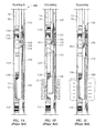
- Figures 2A-2C show the crossover tool 140 according to the prior art disposed in portion of the gravel pack assembly 100
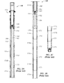
- Figures 3A-3C show the crossover tool 140 according to the prior art in detail.
- the gravel pack assembly 100 has the packer 110 and the extension 120. Well screens and other components are not shown in these Figures.
- This crossover tool 140 is similar to the "Model 4P Crossover Tool” available from Weatherford.
- a setting tool 142 (only a portion of which is shown) on the crossover tool 140 is used to set the packer 110 in the borehole.
- Upper and lowers housings 150 and 170 on the tool 140 have multiple subassemblies 151/171 with bonded seals 153/173 disposed thereabout for engaging in the gravel pack assembly 100.
- the crossover tool 140 has four upper subassemblies 151 a-d coupled to one another and uses four external seal rings 153.
- the tool 140 has a ported subassembly 155 having the crossover ports 156 and the return bypass 158. Additionally, the crossover tool 140 can have eleven lower subassemblies 171 a-k coupled to one another below the ported subassembly 155 and can use twelve external seal rings 173.
- the crossover tool 140 can become stuck in the gravel pack assembly 100, and efforts to retrieve the stuck tool 140 can lead to mechanical failures.
- operators have attempted to reduce any void spaces where gravel can settle around the crossover tool inside the gravel pack extension.
- the crossover tool can use a check valve in an evacuation port, such as disclosed in U.S. Pat. No. 7,032,666 . After pumping the sand downhole and before trying to move the crossover tool, the check valve allows operators to pump fluid down the casing to evacuate any residual sand from where it is likely to settle.
- the standard crossover tool such tool 140 shown in Figures 2A-2C and 3A-3C ,has numerous outward facing seal rings 153/173 mounted on the crossover tool 140. These rings 153/173 move through the stationary polished sealing surfaces 126 ( Fig. 2B )of theextension'sbore122 inside the gravel pack assembly 100.
- the seal rings153/173 move through the stationary polished sealing surfaces 126 ( Fig. 2B )of theextension'sbore122 inside the gravel pack assembly 100.
- the subject matter of the present disclosure is directed to overcoming, or at least reducing the effects of, one or more of the problems set forth above.
- a borehole gravel pack assembly has a longitudinal body that disposes in a borehole.
- the body has a packer that engages in the borehole to isolate a portion of the annulus.
- the body also has an extension that extends downhole from the packer.
- a well screen and other component connect to the extension and complete the gravel pack assembly.
- an inner passage passes from end to end through the packer and extension, and a flow port defined in the extension communicates the inner passage outside the body to the isolated annulus of the borehole.
- This flow port allows fluid (e.g. , slurry, gravel, frac fluids, etc.) to communicate between the extension and the borehole annulus during gravel pack and frac pack operations.
- a crossover tool is manipulated in the packer and extension to direct slurry and fluids during the gravel pack and frac pack operations.
- the crossover tool has an open distal end that allows fluid returns to pass up the tool to a workstring or the borehole above the packer depending on the position of the tool.
- the crossover tool also has a cross port that can communicate with the extension's flow port.
- the tool has a bypass port at its uphole end that can communicate with the borehole above the packer depending on the tool's position.
- the crossover tool For sealing inside the assembly, the crossover tool has a uniform and smooth exterior surface on both sides of the cross port, and the assembly has one or more packoff seals or bushings disposed in the inner passage of the extension downhole of the flow ports.
- the smooth exterior surface seals against these one or more packoff seals or bushings when disposed relative thereto.
- This form of sealing prevents passage of sand and fluids between the tool and the assembly's inner passage.
- the crossover tool is less likely to become stuck in the inner passage of the assembly when manipulated during operations.
- the packoff seals or bushings can be disposed downhole of the assembly's flow ports. Additionally, one or more packoff seals or bushings can be similarly disposed in the inner passage uphole of the flow ports. These packoff seals or bushings can be disposed in the bore of the packer, in a portion of the extension, or in a juncture connecting the components together. In any event, the seals or bushings define an internal diameter less than the diameter of the inner passage so the seals or bushings can engage the external surface of the crossover tool.
- these seals or bushings are fixed in the inner passage and can be bushing rings disposed in internal grooves in the passage.
- the seals or bushings can be activated between activated and inactivated conditions.
- a sliding sleeve can move the flexible fingers having distal ends, or some other form of movement of the fingers can be used. When moved, the fingers' distal ends can contract together to form an inner diameter as needed during operations to create the sealing interface with the tool's smooth external surface.
- a borehole gravel pack assembly comprising:
- a portion of the inner passage of the body may comprise a reduced diameter, the packoff seal disposed at the reduced diameter.
- the packoff seal may comprise a pair of bushings disposed inside the reduced diameter.
- the bushings may dispose in internal grooves defined about the reduced diameter.
- the packoff seal may be movable between an inactivated condition and an activated condition in the inner passage, the packoff seal in the activated condition engaging the smooth exterior surface of the crossover tool when disposed relative thereto.
- the body may comprise a sleeve movably disposed in the inner passage, the sleeve moving the packoff seal between the inactivated and activated conditions.
- the crossover tool may comprise a shifter disposed thereon, the shifter selectively moving the sleeve in the inner passage when shifted relative thereto.
- the packoff seal may comprise a plurality of flexible fingers movable with the sleeve, distal ends of the flexible fingers contracting together when in the activated condition and forming a reduced diameter for sealing against the smooth exterior surface of the crossover tool.
- the assembly may further comprise another packoff seal disposed in the inner passage of the body between the first port and the proximal end, wherein the smooth exterior surface of the crossover tool seals against the other packoff seal when disposed relative thereto.
- the body may comprise means disposed outside the body for engaging in the borehole.
- the open distal end of the crossover tool may comprise a one-way valve permitting fluid communicating into the crossover tool.
- the body may comprise a well screen disposed on the distal end and communicating the borehole with the inner passage of the body.
- the crossover tool disposed in the body is a crossover tool disposed in the body:
- the crossover tool may comprise:
- the crossover tool may comprise means disposed between the first passage and the cross port for selectively preventing fluid communication from the first passage out the cross port.
- the outer housing may comprise an intermediate portion defining a bypass passage communicating with the first and second ends, the intermediate portion defining the cross port communicating the first open end outside a side of the intermediate portion.
- the outer housing may comprise:
- the first and second tubulars may each have a portion of the smooth exterior surface of the crossover tool.
- a borehole gravel pack assembly comprising:
- the means for sealing may comprise means for activating the sealing against the smooth exterior surface.
- the means for sealing may comprise:
- a gravel pack assembly 200 in Figures 4A-C uses a different sealing arrangement than the multiple subassemblies and outward facing seals of the prior art.
- a packer 210 and extension 220 of the assembly 200 have inner seals or bushings to engage a smooth external surface of a crossover tool 240.
- the packer210 disposes in a borehole (not shown) and has features to engage the borehole wall, which can be cased or uncased.
- the packer 210 has a packing element 216 and slips 218 that can be activated to engage the borehole.
- the gravel pack extension220 extends from the packer 210, and the crossover tool 240 can position in various operating positions in the packer 210 and extension 220. Together, these components of the assembly 200 can be used for fracing, gravel packing, and frac/packing. Accordingly, the packer 210 and extension 220 can be used with well screens and other components for production in the borehole.
- the packer 210 has a mandrel 212 with an innerbore214extending from an uphole end to a downhole end. To engage the surrounding borehole, the packer 210 has the packing element 216 and the slips 218 disposed on the outside of the mandrel 212, and conventional activation can be used to activate the packing element 216 and slips 218.
- the gravel pack extension 220 extends from the packer 210, and an inner bore 222 of the extension 220 communicates with the packer's bore 214.
- the extension 220 can have an extended upper portion that accommodates upper and lower circulating positions and can have a lower portion that extends therefrom. This lower portion can be a standard tubular or the like.
- the extension 220 connects to other components, such as a well screen, downhole packer, and other elements as detailed previously.
- the extension 220 defines flow ports 224 that communicate the inner bore 222 outside the extension 220 to the surrounding annulus. In between the extension's flow ports 224 and the lower end 223, the extension 220 has a juncture 226 ( Fig. 4B ) with packoff seals or bushings 228a-b disposed in the extension's inner bore 222.
- the seals or bushings 228a-b can be composed of a resilient metal and other materials and may comprise a unitary ring, a split C-ring, a segmented ring, a plain bearing, a sleeve, a clenched bushing, or the like. (In the present disclosure, seal or bushing may be used interchangeably.)
- the inner diameter of the juncture 226 can be smaller than the extension's bore 222, and the pack-off bushings 228a-b can have a smaller diameter than the juncture's bore. In this way, the packoff bushings 228a-b can engage the crossover tool 140 when disposed therein as described in more detail below.
- the crossover tool 240 disposes in the inner bores 214/222 of the mandrel 212 and extension 220 as shown in Figures 4A-4C . (Isolated details of the crossover tool 240 are shown in the views of Figure 5A-5C .)Overall, the crossover tool240hasa longitudinal tubular body 242 with a smooth exterior surface 241 that runs uniformly along its length.
- An upper end of the tubular body 242 has an external seal 243 and a latch mandrel 244 for selective sealing as described herein.
- the external seal 243 engages in the packer's bore 214 when the crossover tool 240 is positioned in a squeeze condition in the assembly 200 ( e.g. , similar to Fig. 1C ) so the return ports 254 do not communicate with the borehole uphole of the packer 210.
- a setting tool 244 attaches to the latch mandrel 244 and is used for setting the packer 210 during operations.
- the lower end of the crossover tool 240 has a check-valve 246 ( i.e., ball and seat arrangement) to accept flow into and prevent flow out the lower end.
- the body 242 is made of several components to facilitate assembly.
- these components include an upper outer housing 250, an intermediate housing 255, and a lower outer housing 270 that connect to one another from the latch mandrel244 to the lower check valve 246.
- an inner housing 260 Disposed inside the upper housing 250, an inner housing 260 extends from the latch mandrel244 to the intermediate housing 255 and has a ball seat 265 that can be selectively sealed as described herein.
- Each of these housings 250/255/260/270 is tubular.
- a cross port 256 in the intermediate housing 255 communicates the inner bore 262 of the upper inner housing 260 outside the crossover tool 240, while a bypass 258 in the intermediate housing 255 communicates the annular space between the outer and inner housings 250/260 with the inner bore 272 of the lower housing 270.
- the ball seat 265 disposed in between the inner housing 260 and the cross-ports 256 can be selectively activated during operations. For example, a ball can be dropped on the ball seat 265 to close off fluid communication. When sufficient pressure is applied for the purpose of setting the packer 210, the ball and the ball seat 265 move in the intermediate housing 255 below the cross ports 256. This allows the inner housing 260 to communicate outside the crossover tool 240 during operations as described herein.
- This crossover tool 240 can be used for conventional operations, especially when conducting a frac-pack operation followed by an annular gravel pack operation.
- the crossover tool 240 situates in a squeeze position in the packer 210 and extension 220 as noted previously ( See e.g., Fig. 1C ).
- the crossover tool 240 is moved into a circulating position ( See e.g., Fig. 1B ) so operators can perform the annular gravel pack operation subsequent to the frac operation.
- tool movement can be generally upward after pumping slurry/proppant, which reduces the chance of sticking.
- the ball seat 265 in the crossover tool 240 Details of the ball seat 265 in the crossover tool 240 are briefly mentioned for completeness. In the run-in position, the ball seat 265 would be open without a ball seated. For the purpose of being able to apply pressure to the setting tool 244 to set the packer 210, the ball seat 265 would be closed with a dropped ball and moved below the cross ports 256. Accordingly, flow can be diverted to the cross ports 256 as described herein. Meanwhile, the lower check valve 246 allows returns to enter the crossover tool 140 from a connected wash pipe (not shown). Squeezing and reversing out positions use the same configuration, although the crossover tool 240 is moved in the assembly 200.
- a standard crossover tool e.g ., 140 of Figs. 2A-2C
- These seal rings (153/173) tend to displace gravel, but compress on the tool (140) enough so the crossover tool (140) can be moved in the wellbore.
- the conventional tool (140) can be prone to sticking in some circumstances.
- the crossover tool240of the present disclosure has the longitudinal body 242 with its exterior surface 241, which can be polished smooth using known techniques.
- the tubular housings250/255/270 with exterior surfaces 251/257/271 create a uniform, smooth exterior surface 241 along the tool's length, even though the tool 240 is made up of the several external housings 250/255/270 coupled together for assembly purposes.
- the exterior surface 241 can engage the packoff bushings 228a-b to seal off communication of fluid and sand in the space between the crossover tool 240 and the body's extension 220 downhole of the gravel pack ports 224.
- the crossover tool 240 is moved, for example, the stationary packoff bushings228a-b in the extension 220 do not move sand, and the bushings' seal material does not compress and bind the crossover tool240.
- the crossover tool 240 can move through an existing column of gravel because the crossover tool 240 essentially has a constant outer diameter along its tubular body 242 without enlarged diameters for seal rings or the like.
- portions inside the packer 210 and/or the extension 220 can also have packoff bushings to engage the external surface 251 uphole of the cross-ports 256 on the tool 240.
- a packoff seal or bushing 215 can be disposed inside the bore 214 of the packer 210 to engage the tool's upper external surface 251 and seal off communication of fluid and sand in the space between the crossover tool 240 and the packer 210 uphole of the cross ports 256.
- One or more than one such seal or bushing 215 can be used and can be similar to the other seals or bushings 228a-b described herein.
- an internal diameter at a juncture 217 ( See Figs. 4A-4B ) of the packer 210 and the extension 220 can have one or more seals or bushings (not shown) similar to those described herein.
- this junction 217 with the internal diameter can be any suitable length to accommodate the bushings and can be similar to the juncture 226 on the extension 220 described previously.
- the crossover tool's polished surface 241 and the assembly's stationary packoff seals or bushings (215, 228a-b, etc.) can reduce the chances of sticking the crossover tool 240 after pumping proppant/slurry. These features can also reduce drag and seal damage when changing tool positions after pumping the proppant/slurry. If operators want to perform an annular gravel pack operation after a frac operation, the tool 240 can be readily moved to a circulating position because change in position only requires upward movement. In the end, the expanding pack- off bushings on the tool 240 allow conventional seal units to be used on the production seal assembly ( i.e. , 190; Fig. 1E ) to seal in the assembly 200.
- the smooth surface 241 to the body 242 gives the crossover tool 240 a low drag profile
- the smooth surface 241 can be susceptible to damage so it is preferably handled accordingly.
- the internal packoff seals or bushings i.e. , 215, 228a-b, etc.
- the internal packoff seals or bushings preferably do not reduce the internal diameter 212 below the packer 210 to such an extent that could obstruct the passage of other tools.
- the extension 220 can have a closing sleeve (not shown) that opens and closes repeatedly with the insertion and withdrawal of the crossover tool 240. After gravel packing, for example, the extension's closing sleeve can be closed to isolate the flow ports 224 and prevent the flow between the extension 220 and the annulus.
- the crossover tool 240 can have a shifter (not shown) disposed thereon-not unlike the shifter shown below with reference to Figure 6B .
- the extension 200 can also have a debris barrier (not shown) spaced to fit in this closing sleeve.
- packoff seal arrangements mounted in the assembly 200 can be operated with movement of the crossover tool 240.
- the dimensions of seals or bushings inside the assembly 200 can expand and contract with the movement of the crossover tool 240 so that the resulting seals can be selectively actuated.
- the bushings 228a-b composed of a resilient metal and other materials can comprise a unitary ring, a split C-ring, or a segmented ring and can change diameter when moved relative to an outer groove in the assembly 200. This arrangement may prevent damage to the bushings 228a-b when other tools are passed through the assembly 200.
- FIG. 6A-6C Another actuatable seal arrangement for the gravel pack assembly 200 is shown in Figures 6A-6C .
- the seal arrangement shown in Figures 6A and 6C uses distal ends 312 on fingers 310, which can be actuated during operations to engage the polished surface 241 of the crossover tool 240.
- a sleeve 300 is disposed in the assembly's juncture 226.
- the sleeve 300 can be similar to the type of closing sleeve used in the extension (220) to selectively open and close fluid communication through the flow ports 224.
- the sleeve 300 has upper and lower catches 302 and 304 and has expandable locks 306 with catches 308.
- the sleeve 300 is intended to selectively lock between two positions using the expanding teeth 304 in surrounding grooves of the mandrel's housing 226.
- Other types of locking features known in the art could also be used.
- Various seals and the like are not shown on the sleeve 300, but these features would be present as needed.
- a number of flexible fingers 310 extend in the bore 227 of the joint 226.
- the distal ends 312 of the fingers 310 flex outward and can fit in an internal groove 314 of the joint 226. This essentially allows passage of tools through the joint 226.
- a shifter 320as shown in Figure 6B disposed on the crossover tool 240 is passed through the bore 227 of the joint 226 when the fingers 310 are expanded out as in Figure 6A .
- the shifter 320 preferably passes through the fingers 310 without damaging them. Therefore, the shifting tool 310 may require an extended ramp to move its components away from the finger's distal ends 312 when passed thereby.
- Operation of the fingers 310 on the sleeve 300 can be similar to a "hydro-set "or "hydro-trip" sub assembly typically used in a downhole tool to form a seat for a dropped ball.
- pressure acting against a seated ball and shearing a shear pin connection does not move the sleeve 300 and fingers 310 of the current arrangement.
- the distal ends 312 on the fingers 310 in the present arrangement come together to form the reduced inner sealing diameter that engages a polished surface 241 on the crossover tool 240.
- the smooth external surface 241 of the crossover tool 240 reaches the activated distal ends 312defining the reduced diameter, and the distal ends 312seal on the polished surface 241 or at least restrict the movement of fluid and solids between the distal ends 312 and the surface 241.
- the fingers 310 can be deactivated so that the distal ends 312 expand away from one another into the surrounding groove 314.
- the upper end of the shifter 320 can engage the fingers 310 and move the sleeve 300 uphole so that the fingers' distal ends 312move back to the corresponding groove314 similar to Figure 6A .
- the distal ends 312 expand outward and no longer contact the crossover tool 240 or other possible tools that may be passed through the juncture 226.
- the shifter's catch 322 must be able to disengage therefrom. Lacking a fixed shoulder on which the shifter's ramp can engage and release the shifter's catch 322 from the sleeve's catch 302, any of a number of other techniques known in the art can be used as will be appreciated one skilled in the art.
- the shifter 300 may have an activatable catch 322 on the shifter 320.
- activation of the fingers 310 can be reversed so that pulling up on the shifter 320 moves the sleeve 300 uphole and pushes the finger's distal ends out of a groove 312. Then, pushing down on the shifter 320 moves the sleeve 300 downhole and pushes the finger's distal ends back into the groove 312.
- the activatable seal arrangement from the fingers 310 can allow a production seal assembly ( See e.g., 190; Fig. 1E ) to use conventional seals when engaging the gravel pack assembly 200.
- a production seal assembly See e.g., 190; Fig. 1E
- any other seal arrangement present on the assembly 200 can also be activatable.
- any seals 215 inside the packer's bore 214 or on an internal diameter at the juncture 217 of the extension 220 and the packer 210 can have one or more similarly activatable seal arrangement.
Landscapes
- Life Sciences & Earth Sciences (AREA)
- Engineering & Computer Science (AREA)
- Geology (AREA)
- Mining & Mineral Resources (AREA)
- Physics & Mathematics (AREA)
- Environmental & Geological Engineering (AREA)
- Fluid Mechanics (AREA)
- General Life Sciences & Earth Sciences (AREA)
- Geochemistry & Mineralogy (AREA)
- Earth Drilling (AREA)
- Consolidation Of Soil By Introduction Of Solidifying Substances Into Soil (AREA)
Abstract
Description
- Operators may perform a gravel or frac pack operation in a well to reduce the inflow of unwanted contaminants. In a gravel pack operation, operators deploy a gravel pack assembly down a wellbore and pump a slurry of liquid and gravel (e.g., sand) down a workstring and redirect the slurry to the annulus. Typically, the gravel pack assembly has a packer to seal the wellbore, a crossover tool connected below the packer to redirect the slurry, and a gravel-pack extension with a screen to filter returns.
- When gravel is pumped downhole, the crossover tool acts as a conduit for the gravel, allowing it to fill in the annulus below the packer and around the screen. As the gravel fills the annulus, it becomes tightly packed and acts as an additional filtering layer along with the well screen to prevent the collapse of the wellbore. When the wellbore is then produced, the gravel around the screen filters the produced fluid produced from the formation and prevents the contaminants from entering the stream of production fluids produced to the surface.
- As shown in
Figures1A-1E , for example, agravel pack assembly 100 extends downhole in aborehole 10, which can be an open or cased hole. Thegravel pack assembly 100 has anuphole packer 110, anextension 120, awell screen 130, and alower packer 135. Acrossover tool 140 disposes through thepacker 110 and into theextension 120 to perform gravel or frac pack operations as detailed below. - After running-in as shown in
Figure 1A , thecrossover tool 140 can be placed in a circulating position (Fig. 1B ), a squeeze position (Fig. 1C ), or a reverse position (Fig. 1D ) depending on the upward and downward movement of the work string. - To circulate through the
assembly 100 as inFigure 1B , for example, operators move thecrossover tool 140 to the circulating position and drop a ball to close and move aninner check valve 165. This allows fluid pumped down theinner workstring 14 to pass out the crossover tool'sports 156 and the extension'sports 124 into the annulus. Returning through thewell screen 130, the circulated fluid can enter the tool'swash pipe 180 and return up thecrossover tool 140 to thereturn ports 154 above thepacker 110. - To frac the formation, for example, operators move the
crossover tool 140 to the squeeze position shown inFigure 1C so thecrossover ports 156 align with theflow ports 124 of the gravel-pack extension 120. During the frac, a slurry of proppant and carrying fluid is pumped into the annulus between the wellscreen 130 and theborehole 10 so the proppant can treat the formation around theborehole 10 by entering throughperforations 12. (An open hole arrangement would not haveperforations 12 and the like.) In this squeeze position, operators pump fluids straight into the formation without transmission of fluid or pressure to the casing annulus above thepacker 110. In this way, fluid can be injected down theworkstring 14 and into the annulus around thescreen 130 without exposing the upper casing to injection pressures and fluid. - To gravel pack, operators fill the annulus between the well
screen 130 and theborehole 10 with gravel by pumping a slurry of fluid and gravel (i.e., graded sand) into theborehole 10 to pack the annulus. For example, moving thecrossover tool 140 to the circulating position shown inFigure 1B exposes theports workstring 14 can circulate in the annulus and around the wellscreen 130. Held by the wellscreen 130, the gravel then packs in the annulus, while return fluids flow through thewell screen 130 and up thewash pipe 180. Eventually, the fluid passes through thereturn bypass 158 of thecrossover tool 140 and outreturn ports 154 into the annulus above thepacker 110. Thus, the circulating position directs the slurry to pack the annulus as discussed previously. - To achieve a reverse position as shown in
Figure 1D , operators raise thecrossover tool 140 further until itscrossover ports 156 dispose uphole of thepacker 110. This isolates the formation so operators can reverse out or circulate fluid above thepacker 110. During recirculation, excess sand slurry can be circulated to the surface after gravel packing has been completed. Finally, as shown inFigure 1E , theassembly 100 can be set up for production by installing aproduction seal assembly 190 in thepacker 110 andextension 120. -
Figures 2A-2C show thecrossover tool 140 according to the prior art disposed in portion of thegravel pack assembly 100, whileFigures 3A-3C show thecrossover tool 140 according to the prior art in detail. As noted previously, thegravel pack assembly 100 has thepacker 110 and theextension 120. Well screens and other components are not shown in these Figures. - This
crossover tool 140 is similar to the "Model 4P Crossover Tool" available from Weatherford. A setting tool 142 (only a portion of which is shown) on thecrossover tool 140 is used to set thepacker 110 in the borehole. Upper and lowershousings tool 140 have multiple subassemblies 151/171 withbonded seals 153/173 disposed thereabout for engaging in thegravel pack assembly 100. In particular, thecrossover tool 140 has four upper subassemblies 151 a-d coupled to one another and uses fourexternal seal rings 153. Thetool 140 has aported subassembly 155 having thecrossover ports 156 and thereturn bypass 158. Additionally, thecrossover tool 140 can have eleven lower subassemblies 171 a-k coupled to one another below theported subassembly 155 and can use twelveexternal seal rings 173. - After the gravel pack operation as in
Figure 1C ,thecrossover tool 140 can become stuck in thegravel pack assembly 100, and efforts to retrieve thestuck tool 140 can lead to mechanical failures. To prevent the tendency of sticking of a crossover tool, operators have attempted to reduce any void spaces where gravel can settle around the crossover tool inside the gravel pack extension. Alternatively, the crossover tool can use a check valve in an evacuation port, such as disclosed inU.S. Pat. No. 7,032,666 . After pumping the sand downhole and before trying to move the crossover tool, the check valve allows operators to pump fluid down the casing to evacuate any residual sand from where it is likely to settle. - Even with these efforts to prevent sticking, the standard crossover tool still has drawbacks. In particular, the standard crossover tool,
such tool 140 shown inFigures 2A-2C and3A-3C ,has numerous outward facingseal rings 153/173 mounted on thecrossover tool 140. Theserings 153/173 move through the stationary polished sealing surfaces 126 (Fig. 2B )of theextension'sbore122 inside thegravel pack assembly 100. When gravel surrounds thecrossover tool 140, moving it through or into the seal bore 122requires the sand to displace or requires the seal rings153/173 to compress enough for thecrossover tool 140 to move. Both of these situations are less than ideal and can result in sticking of thetool 140 in theassembly 140. - The subject matter of the present disclosure is directed to overcoming, or at least reducing the effects of, one or more of the problems set forth above.
- A borehole gravel pack assembly has a longitudinal body that disposes in a borehole. The body has a packer that engages in the borehole to isolate a portion of the annulus. The body also has an extension that extends downhole from the packer. A well screen and other component connect to the extension and complete the gravel pack assembly.
- On the body, an inner passage passes from end to end through the packer and extension, and a flow port defined in the extension communicates the inner passage outside the body to the isolated annulus of the borehole. This flow port allows fluid (e.g., slurry, gravel, frac fluids, etc.) to communicate between the extension and the borehole annulus during gravel pack and frac pack operations.
- A crossover tool is manipulated in the packer and extension to direct slurry and fluids during the gravel pack and frac pack operations. In particular, the crossover tool has an open distal end that allows fluid returns to pass up the tool to a workstring or the borehole above the packer depending on the position of the tool. The crossover tool also has a cross port that can communicate with the extension's flow port. Finally, the tool has a bypass port at its uphole end that can communicate with the borehole above the packer depending on the tool's position.
- For sealing inside the assembly, the crossover tool has a uniform and smooth exterior surface on both sides of the cross port, and the assembly has one or more packoff seals or bushings disposed in the inner passage of the extension downhole of the flow ports. When the tool disposes in the packer and extension, the smooth exterior surface seals against these one or more packoff seals or bushings when disposed relative thereto. This form of sealing prevents passage of sand and fluids between the tool and the assembly's inner passage. Moreover, by having a smooth external surface along its length, the crossover tool is less likely to become stuck in the inner passage of the assembly when manipulated during operations.
- As noted above, the packoff seals or bushings can be disposed downhole of the assembly's flow ports. Additionally, one or more packoff seals or bushings can be similarly disposed in the inner passage uphole of the flow ports. These packoff seals or bushings can be disposed in the bore of the packer, in a portion of the extension, or in a juncture connecting the components together. In any event, the seals or bushings define an internal diameter less than the diameter of the inner passage so the seals or bushings can engage the external surface of the crossover tool.
- In one arrangement, these seals or bushings are fixed in the inner passage and can be bushing rings disposed in internal grooves in the passage. In an alternative arrangement, the seals or bushings can be activated between activated and inactivated conditions. For example, a sliding sleeve can move the flexible fingers having distal ends, or some other form of movement of the fingers can be used. When moved, the fingers' distal ends can contract together to form an inner diameter as needed during operations to create the sealing interface with the tool's smooth external surface.
- According to one aspect of the present invention there is provided a borehole gravel pack assembly, comprising:
- a body disposing in the borehole, the body having an inner passage from a proximal end to a distal end and defining a flow port communicating the inner passage outside the body;
- a packoff seal disposed in the inner passage of the body between the first port and the distal end; and
- a crossover tool disposing in the inner passage of the body, the crossover tool having first and second open ends, a cross port, and a return port, the crossover tool having a smooth exterior surface on both sides of the cross port, the smooth exterior surface sealing against the packoff seal when disposed relative thereto.
- A portion of the inner passage of the body may comprise a reduced diameter, the packoff seal disposed at the reduced diameter.
- The packoff seal may comprise a pair of bushings disposed inside the reduced diameter.
- The bushings may dispose in internal grooves defined about the reduced diameter.
- The packoff seal may be movable between an inactivated condition and an activated condition in the inner passage, the packoff seal in the activated condition engaging the smooth exterior surface of the crossover tool when disposed relative thereto.
- The body may comprise a sleeve movably disposed in the inner passage, the sleeve moving the packoff seal between the inactivated and activated conditions.
- The crossover tool may comprise a shifter disposed thereon, the shifter selectively moving the sleeve in the inner passage when shifted relative thereto.
- The packoff seal may comprise a plurality of flexible fingers movable with the sleeve, distal ends of the flexible fingers contracting together when in the activated condition and forming a reduced diameter for sealing against the smooth exterior surface of the crossover tool.
- The assembly may further comprise another packoff seal disposed in the inner passage of the body between the first port and the proximal end, wherein the smooth exterior surface of the crossover tool seals against the other packoff seal when disposed relative thereto.
- The body may comprise means disposed outside the body for engaging in the borehole.
- The open distal end of the crossover tool may comprise a one-way valve permitting fluid communicating into the crossover tool.
- The body may comprise a well screen disposed on the distal end and communicating the borehole with the inner passage of the body.
- The crossover tool disposed in the body:
- in a first position, may dispose the cross port in fluid communication with the flow port of the body and dispose the return port in fluid communication with the borehole uphole of the body,
- in a second position, may dispose the cross port in fluid communication with the flow port of the body and seal the return port from fluid communication with the borehole uphole of the body, and
- in a third position, may dispose the cross port in fluid communication with the borehole uphole of the body.
- The crossover tool may comprise:
- an inner housing defining a first passage communicating with the first open end; and
- an outer housing defining a second passage communicating with the first and second open ends and disposed about the inner housing, the return port defined in the outer housing and communicating the second passage outside the outer housing, the cross port defined in the outer housing and communicating the first passage outside the outer housing.
- The crossover tool may comprise means disposed between the first passage and the cross port for selectively preventing fluid communication from the first passage out the cross port.
- The outer housing may comprise an intermediate portion defining a bypass passage communicating with the first and second ends, the intermediate portion defining the cross port communicating the first open end outside a side of the intermediate portion.
- The outer housing may comprise:
- a first tubular connected to one end of the intermediate portion; and
- a second tubular connected to another end of the intermediate portion.
- The first and second tubulars may each have a portion of the smooth exterior surface of the crossover tool.
- According to another aspect of the invention there is provided a borehole gravel pack assembly, comprising:
- a body disposing in the borehole and having first and second ends, the body having an inner passage from the first end to the second end and defining a flow port communicating the inner passage outside the body;
- a crossover tool disposing in the inner passage of the body, the crossover tool having first and second open ends, a cross port, and a return port, the crossover tool having a smooth exterior surface on both sides of the cross port; and
- means disposed in the inner passage of the body for sealing against the smooth exterior surface of the crossover tool when disposed relative thereto.
- The means for sealing may comprise means for activating the sealing against the smooth exterior surface.
- The means for sealing may comprise:
- first means for sealing a first portion of the smooth exterior surface downhole of the cross port; and
- second means for sealing a second portion of the smooth exterior surface uphole of the cross port.
- The foregoing summary is not intended to summarize each potential embodiment or every aspect of the present disclosure.
-
-
Figs. 1A-1E shows a gravel pack assembly according to the prior art during different operation conditions. -
Figs. 2A-2C show a crossover tool according to the prior art disposed in portion of a gravel pack assembly. -
Figs. 3A-3C show the crossover tool according to the prior art in more detail. -
Figs.4A-4C show a crossover tool of the present disclosure disposed in portion of a gravel pack assembly. -
Figs. 5A-5C showthe crossover tool of the present disclosure in more detail. -
Figs. 6A-6C show an alternative packoff seal arrangement for the gravel pack assembly that can be activated during operations. - To deal with problems of a crossover tool sticking in a gravel pack assembly, a
gravel pack assembly 200 inFigures 4A-C uses a different sealing arrangement than the multiple subassemblies and outward facing seals of the prior art. As will be detailed below, apacker 210 andextension 220 of theassembly 200 have inner seals or bushings to engage a smooth external surface of acrossover tool 240. - The packer210disposes in a borehole (not shown) and has features to engage the borehole wall, which can be cased or uncased. Typically, the
packer 210 has apacking element 216 and slips 218 that can be activated to engage the borehole. The gravel pack extension220 extends from thepacker 210, and thecrossover tool 240 can position in various operating positions in thepacker 210 andextension 220. Together, these components of theassembly 200 can be used for fracing, gravel packing, and frac/packing. Accordingly, thepacker 210 andextension 220 can be used with well screens and other components for production in the borehole. - When the
packer 210,extension 220, well screen and the like are deployed down the borehole, operators set thepacker 210 and begin pumping slurry (proppant and/or gravel) after thecrossover tool 240 is disposed for circulating in thepacker 210 andextension 220. Thecrossover tool 240 diverts the pumped slurry to the borehole annulus, and the slurry treats the formation or fills the annulus around the extension's screen (not shown) depending on the type of operation. Many of the details of thegravel pack assembly 200 includingpacker 210,extension 220, andcrossover tool 240 and how theassembly 200 operates are similar to those described previously. - Looking in more detail, the
packer 210 has amandrel 212 with an innerbore214extending from an uphole end to a downhole end. To engage the surrounding borehole, thepacker 210 has thepacking element 216 and theslips 218 disposed on the outside of themandrel 212, and conventional activation can be used to activate thepacking element 216 and slips 218. - The
gravel pack extension 220 extends from thepacker 210, and aninner bore 222 of theextension 220 communicates with the packer'sbore 214. In general, theextension 220 can have an extended upper portion that accommodates upper and lower circulating positions and can have a lower portion that extends therefrom. This lower portion can be a standard tubular or the like. At itsdistal end 223, theextension 220 connects to other components, such as a well screen, downhole packer, and other elements as detailed previously. - The
extension 220 definesflow ports 224 that communicate theinner bore 222 outside theextension 220 to the surrounding annulus. In between the extension'sflow ports 224 and thelower end 223, theextension 220 has a juncture 226 (Fig. 4B ) with packoff seals orbushings 228a-b disposed in the extension'sinner bore 222. In general, the seals orbushings 228a-b can be composed of a resilient metal and other materials and may comprise a unitary ring, a split C-ring, a segmented ring, a plain bearing, a sleeve, a clenched bushing, or the like. (In the present disclosure, seal or bushing may be used interchangeably.) - As shown, the inner diameter of the
juncture 226 can be smaller than the extension'sbore 222, and the pack-off bushings 228a-b can have a smaller diameter than the juncture's bore. In this way, the packoff bushings 228a-b can engage thecrossover tool 140 when disposed therein as described in more detail below. - Looking now at the
crossover tool 240 in more detail, thecrossover tool 240 disposes in theinner bores 214/222 of themandrel 212 andextension 220 as shown inFigures 4A-4C . (Isolated details of thecrossover tool 240 are shown in the views ofFigure 5A-5C .)Overall, the crossover tool240hasa longitudinaltubular body 242 with a smoothexterior surface 241 that runs uniformly along its length. - An upper end of the
tubular body 242 has anexternal seal 243 and alatch mandrel 244 for selective sealing as described herein. Theexternal seal 243 engages in the packer'sbore 214 when thecrossover tool 240 is positioned in a squeeze condition in the assembly 200 (e.g., similar toFig. 1C ) so thereturn ports 254 do not communicate with the borehole uphole of thepacker 210. Asetting tool 244 attaches to thelatch mandrel 244 and is used for setting thepacker 210 during operations. The lower end of thecrossover tool 240 has a check-valve 246 (i.e., ball and seat arrangement) to accept flow into and prevent flow out the lower end. - The
body 242 is made of several components to facilitate assembly. For the exterior of thetool 240, these components include an upperouter housing 250, anintermediate housing 255, and a lowerouter housing 270 that connect to one another from the latch mandrel244 to thelower check valve 246. Disposed inside theupper housing 250, aninner housing 260 extends from the latch mandrel244 to theintermediate housing 255 and has aball seat 265 that can be selectively sealed as described herein. Each of thesehousings 250/255/260/270 is tubular. - A
cross port 256 in theintermediate housing 255 communicates theinner bore 262 of the upperinner housing 260 outside thecrossover tool 240, while abypass 258 in theintermediate housing 255 communicates the annular space between the outer andinner housings 250/260 with theinner bore 272 of thelower housing 270. - The
ball seat 265 disposed in between theinner housing 260 and thecross-ports 256 can be selectively activated during operations. For example, a ball can be dropped on theball seat 265 to close off fluid communication. When sufficient pressure is applied for the purpose of setting thepacker 210, the ball and theball seat 265 move in theintermediate housing 255 below thecross ports 256. This allows theinner housing 260 to communicate outside thecrossover tool 240 during operations as described herein. - This
crossover tool 240 can be used for conventional operations, especially when conducting a frac-pack operation followed by an annular gravel pack operation. In the frac stage, thecrossover tool 240 situates in a squeeze position in thepacker 210 andextension 220 as noted previously (See e.g.,Fig. 1C ). Afterwards, thecrossover tool 240 is moved into a circulating position (See e.g.,Fig. 1B ) so operators can perform the annular gravel pack operation subsequent to the frac operation. In these operations, tool movement can be generally upward after pumping slurry/proppant, which reduces the chance of sticking. - Details of the
ball seat 265 in thecrossover tool 240 are briefly mentioned for completeness. In the run-in position, theball seat 265 would be open without a ball seated. For the purpose of being able to apply pressure to thesetting tool 244 to set thepacker 210, theball seat 265 would be closed with a dropped ball and moved below thecross ports 256. Accordingly, flow can be diverted to thecross ports 256 as described herein. Meanwhile, thelower check valve 246 allows returns to enter thecrossover tool 140 from a connected wash pipe (not shown). Squeezing and reversing out positions use the same configuration, although thecrossover tool 240 is moved in theassembly 200. Having an understanding of thepacker 210, theextension 220, and thecrossover tool 240, discussion now turns to features of theassembly 200 that overcome problems with potential sticking of thetool 240 in thepacker 210 andextension 220. As noted in the background of the present disclosure, a standard crossover tool (e.g., 140 ofFigs. 2A-2C ) has outward-facing seal rings (153/173) that are moved through the stationary polished sealing surfaces (126)of the bore (122) inside the gravel pack assembly (100). These seal rings (153/173) tend to displace gravel, but compress on the tool (140) enough so the crossover tool (140) can be moved in the wellbore. Yet, the conventional tool (140) can be prone to sticking in some circumstances. - In contrast to this conventional approach and to mitigate issues with sticking, the crossover tool240of the present disclosure has the
longitudinal body 242 with itsexterior surface 241, which can be polished smooth using known techniques. In other words, the tubular housings250/255/270 withexterior surfaces 251/257/271 create a uniform, smoothexterior surface 241 along the tool's length, even though thetool 240 is made up of the severalexternal housings 250/255/270 coupled together for assembly purposes. - The
exterior surface 241 can engage the packoff bushings 228a-b to seal off communication of fluid and sand in the space between thecrossover tool 240 and the body'sextension 220 downhole of thegravel pack ports 224. When thecrossover tool 240 is moved, for example, the stationary packoff bushings228a-b in theextension 220 do not move sand, and the bushings' seal material does not compress and bind the crossover tool240. Moreover, thecrossover tool 240 can move through an existing column of gravel because thecrossover tool 240 essentially has a constant outer diameter along itstubular body 242 without enlarged diameters for seal rings or the like. - Because the
upper housing 250 also has its smoothexternal surface 251 that makes up the body's overall smoothexternal surface 241, portions inside thepacker 210 and/or theextension 220 can also have packoff bushings to engage theexternal surface 251 uphole of the cross-ports 256 on thetool 240. As shown inFigure 4A , for example, a packoff seal orbushing 215 can be disposed inside thebore 214 of thepacker 210 to engage the tool's upperexternal surface 251 and seal off communication of fluid and sand in the space between thecrossover tool 240 and thepacker 210 uphole of thecross ports 256. One or more than one such seal orbushing 215 can be used and can be similar to the other seals orbushings 228a-b described herein. - As an alternative or in addition to such a seal or
bushing 215 in thepacker 210, an internal diameter at a juncture 217 (SeeFigs. 4A-4B ) of thepacker 210 and theextension 220 can have one or more seals or bushings (not shown) similar to those described herein. In fact, thisjunction 217 with the internal diameter can be any suitable length to accommodate the bushings and can be similar to thejuncture 226 on theextension 220 described previously. - The crossover tool's
polished surface 241 and the assembly's stationary packoff seals or bushings (215, 228a-b, etc.) can reduce the chances of sticking thecrossover tool 240 after pumping proppant/slurry. These features can also reduce drag and seal damage when changing tool positions after pumping the proppant/slurry. If operators want to perform an annular gravel pack operation after a frac operation, thetool 240 can be readily moved to a circulating position because change in position only requires upward movement. In the end, the expanding pack- off bushings on thetool 240 allow conventional seal units to be used on the production seal assembly (i.e., 190;Fig. 1E ) to seal in theassembly 200. - Although the
smooth surface 241 to thebody 242 gives the crossover tool 240 a low drag profile, thesmooth surface 241 can be susceptible to damage so it is preferably handled accordingly. Moreover, the internal packoff seals or bushings (i.e., 215, 228a-b, etc.) preferably do not reduce theinternal diameter 212 below thepacker 210 to such an extent that could obstruct the passage of other tools. - If desired, the
extension 220 can have a closing sleeve (not shown) that opens and closes repeatedly with the insertion and withdrawal of thecrossover tool 240. After gravel packing, for example, the extension's closing sleeve can be closed to isolate theflow ports 224 and prevent the flow between theextension 220 and the annulus. Thus, thecrossover tool 240 can have a shifter (not shown) disposed thereon-not unlike the shifter shown below with reference toFigure 6B . Additionally, theextension 200 can also have a debris barrier (not shown) spaced to fit in this closing sleeve. - In a further feature, packoff seal arrangements mounted in the
assembly 200 can be operated with movement of thecrossover tool 240. For example, the dimensions of seals or bushings inside theassembly 200 can expand and contract with the movement of thecrossover tool 240 so that the resulting seals can be selectively actuated. For example, thebushings 228a-b composed of a resilient metal and other materials can comprise a unitary ring, a split C-ring, or a segmented ring and can change diameter when moved relative to an outer groove in theassembly 200. This arrangement may prevent damage to thebushings 228a-b when other tools are passed through theassembly 200. - Another actuatable seal arrangement for the
gravel pack assembly 200 is shown inFigures 6A-6C . In contrast to having fixed or movable bushings as described previously, the seal arrangement shown inFigures 6A and 6C uses distal ends 312 onfingers 310, which can be actuated during operations to engage thepolished surface 241 of thecrossover tool 240. - As shown in
Figure 6A , asleeve 300 is disposed in the assembly'sjuncture 226. In general, thesleeve 300 can be similar to the type of closing sleeve used in the extension (220) to selectively open and close fluid communication through theflow ports 224. Thus, thesleeve 300 has upper andlower catches expandable locks 306 withcatches 308. When shifted, thesleeve 300 is intended to selectively lock between two positions using the expandingteeth 304 in surrounding grooves of the mandrel'shousing 226. Other types of locking features known in the art could also be used. Various seals and the like are not shown on thesleeve 300, but these features would be present as needed. - Attached to the
sleeve 300, a number offlexible fingers 310 extend in thebore 227 of the joint 226. When inactivated as shown inFigure 6A , the distal ends 312 of thefingers 310 flex outward and can fit in aninternal groove 314 of the joint 226. This essentially allows passage of tools through the joint 226. - To activate this seal arrangement, a shifter 320as shown in
Figure 6B disposed on thecrossover tool 240 is passed through thebore 227 of the joint 226 when thefingers 310 are expanded out as inFigure 6A . As theshifter 320 passes into thesleeve 300, theshifter 320 preferably passes through thefingers 310 without damaging them. Therefore, the shiftingtool 310 may require an extended ramp to move its components away from the finger's distal ends 312 when passed thereby. - Eventually, one of the shifter's
catches 322 engages the shiftingsleeve 300 on itslower catch 304. At this point, thesleeve 300 then shifts with the downhole movement of the shifter 320.Thefingers 310 moves with thesleeve 300, and the fingers' distal ends 312 leave the surroundinggroove 314. As this occurs, the distal ends 312 flex together and form a reduced inner sealing diameter similar to the reduced diameter of the previously described seals or bushings. - Operation of the
fingers 310 on thesleeve 300 can be similar to a "hydro-set "or "hydro-trip" sub assembly typically used in a downhole tool to form a seat for a dropped ball. In stark contrast to such a sub assembly, pressure acting against a seated ball and shearing a shear pin connection does not move thesleeve 300 andfingers 310 of the current arrangement. Additionally, the distal ends 312 on thefingers 310 in the present arrangement come together to form the reduced inner sealing diameter that engages apolished surface 241 on thecrossover tool 240. As shown inFigure 6C , for example, the smoothexternal surface 241 of thecrossover tool 240 reaches the activated distal ends 312defining the reduced diameter, and the distal ends 312seal on thepolished surface 241 or at least restrict the movement of fluid and solids between the distal ends 312 and thesurface 241. - When the
crossover tool 240 is withdrawn, thefingers 310 can be deactivated so that the distal ends 312 expand away from one another into the surroundinggroove 314. For example, as the shifter 320on thecrossover tool 240 travels uphole into thesleeve 300, the upper end of the shifter 320can engage thefingers 310 and move thesleeve 300 uphole so that the fingers' distal ends 312move back to the corresponding groove314 similar toFigure 6A . In this position, the distal ends 312 expand outward and no longer contact thecrossover tool 240 or other possible tools that may be passed through thejuncture 226. - As will be evident, if an
upper catch 302 is used to move thesleeve 300, the shifter'scatch 322 must be able to disengage therefrom. Lacking a fixed shoulder on which the shifter's ramp can engage and release the shifter'scatch 322 from the sleeve'scatch 302, any of a number of other techniques known in the art can be used as will be appreciated one skilled in the art. As one example, theshifter 300 may have anactivatable catch 322 on theshifter 320. - As will be appreciated, activation of the
fingers 310 can be reversed so that pulling up on theshifter 320 moves thesleeve 300 uphole and pushes the finger's distal ends out of agroove 312. Then, pushing down on theshifter 320 moves thesleeve 300 downhole and pushes the finger's distal ends back into thegroove 312. - The activatable seal arrangement from the fingers 310can allow a production seal assembly (See e.g., 190;
Fig. 1E ) to use conventional seals when engaging the gravel pack assembly 200.Moreover, any other seal arrangement present on theassembly 200 can also be activatable. For example, anyseals 215 inside the packer'sbore 214 or on an internal diameter at thejuncture 217 of theextension 220 and thepacker 210 can have one or more similarly activatable seal arrangement. - The foregoing description of preferred and other embodiments is not intended to limit or restrict the scope or applicability of the inventive concepts conceived of by the Applicants. It will be appreciated with the benefit of the present disclosure that features described above in accordance with any embodiment or aspect of the disclosed subject matter can be utilized, either alone or in combination, with any other described feature, in any other embodiment or aspect of the disclosed subject matter.
- In exchange for disclosing the inventive concepts contained herein, the Applicants desire all patent rights afforded by the appended claims. Therefore, it is intended that the appended claims include all modifications and alterations to the full extent that they come within the scope of the following claims or the equivalents thereof.
Claims (15)
- A borehole gravel pack assembly (200), comprising:a body (210, 212, 220) disposing in the borehole and having first and second ends, the body (210, 212, 220) having an inner passage (214, 222) from the first end to the second end and defining a flow port (224) communicating the inner passage (214, 222) outside the body (210, 212, 220);a crossover tool (240) disposing in the inner passage (214, 222) of the body (210, 212, 220), the crossover tool (240)having first and second open ends, a cross port (256), and a return port (254), the crossover tool (240)having a smooth exterior surface (241) on both sides of the cross port (256); andmeans(215, 228a-b, 312) disposed in the inner passage (214, 222) of the body (210, 212, 220) for sealing against the smooth exterior surface (241) of the crossover tool (240)when disposed relative thereto.
- The assembly of claim 1, wherein the means for sealing comprises means (312) for activating the sealing against the smooth exterior surface (241).
- The assembly of claim 1 or 2, wherein the means for sealing comprises:first means (228a-b) for sealing a first portion of the smooth exterior surface (241) downhole of the cross port (256); andsecond means (215) for sealing a second portion of the smooth exterior surface (241) uphole of the cross port (256).
- The assembly of claim 1, 2 or 3, wherein the means for sealing comprises:a packoff seal (228a-b) disposed in the inner passage (214, 222) of the body (210, 212, 220) between the flowport (224) and the second end; and whereby the smooth exterior surface (241)of the crossover tool (240) seals against the packoff seal (228a-b) when disposed relative thereto.
- The assembly of claim 4, wherein a portion of the inner passage (214, 222) of the body (210, 212, 220) comprises a reduced diameter, the packoff seal(228a-b) disposed at the reduced diameter; and optionally wherein the packoff seal (228a-b) comprises a pair of bushings(228a-b) disposed inside the reduced diameter; and further optionally wherein the bushings(228a-b) dispose in internal grooves defined about the reduced diameter.
- The assembly of claim 4 or 5, wherein the packoff seal (312) is movable between an inactivated condition and an activated condition in the inner passage (214, 222), the packoff seal (312) in the activated condition engaging the smooth exterior surface (241) of the crossover tool (240) when disposed relative thereto.
- The assembly of claim 6, wherein the body (210, 212, 220) comprises a sleeve (300) movably disposed in the inner passage (214, 222), the sleeve (300) moving the packoff seal (312)between the inactivated and activated conditions.
- The assembly of claim 7,
wherein the crossover tool (240)comprises a shifter (320) disposed thereon, the shifter (320) selectively moving the sleeve (300) in the inner passage (214, 222) when shifted relative thereto; and/or
wherein the packoff seal (312) comprises a plurality of flexible fingers (310) movable with the sleeve (300), distal ends (312) of the flexible fingers (310) contracting together when in the activated condition and forming a reduced diameter for sealing against the smooth exterior surface (241) of the crossover tool (240). - The assembly of any of claims 4 to 8, further comprising another packoff seal (215) disposed in the inner passage (214, 222) of the body (210, 212, 220) between the flowport (224)and the first end, wherein the smooth exterior surface (241) of the crossover tool (240)seals against the other packoff seal (215) when disposed relative thereto.
- The assembly of any one of the preceding claims, wherein the body (210, 212, 220) comprises means (216, 218) disposed outside the body (210, 212, 220)for engaging in the borehole.
- The assembly of any one of the preceding claims, wherein the open distal end of the crossover tool(240)comprises a one-way valve (246) permitting fluid communicating into the crossover tool (240).
- The assembly of any one of the preceding claims, wherein the body (210, 212, 220) comprises a well screen (130) disposed on the distal end and communicating the borehole with the inner passage (214, 222) of the body (210, 212, 220).
- The assembly of any one of the preceding claims, wherein the crossover tool (240)disposed in the body (210, 212, 220):in a first position, disposes the cross port (256) in fluid communication with the flow port (224) of the body (210, 212, 220) and disposes the return port (254) in fluid communication with the borehole uphole of the body (210, 212, 220),in a second position, disposes the cross port (256) in fluid communication with the flow port (224) of the body (210, 212, 220) and seals the return port (254)from fluid communication with the borehole uphole of the body (210, 212, 220), andin a third position, disposes the cross port (256) in fluid communication with the borehole uphole of the body (210, 212, 220).
- The assembly of any one of the preceding claims, wherein the crossover tool (240)comprises:an inner housing (260) defining a first passage (262) communicating with the first open end; andan outer housing (250, 255, 270) defining a second passage (252, 272) communicating with the first and second open ends and disposed about the inner housing (260), the return port (254) defined in the outer housing ((250, 255, 270) and communicating the second passage (252) outside the outer housing (250, 255, 270), the cross port (256) defined in the outer housing (250, 255, 270) and communicating the first passage (262) outside the outer housing (250, 255, 270).
- The assembly of claim 14,
wherein the crossover tool (240)comprises means(265) disposed between the first passage (262) and the cross port (256)for selectively preventing fluid communication from the first passage (262) out the cross port (256); and/or wherein the outer housing(250, 255, 270) comprises an intermediate portion (255) defining a bypass passage (258) communicating with the first and second ends, the intermediate portion (255) defining the cross port (256)communicating the first open end outside a side of the intermediate portion (255), and optionally wherein the outer housing (250, 255, 270) comprises a first tubular (250) connected to one end of the intermediate portion (255) and a second tubular (270) connected to another end of the intermediate portion (255); and further optionally wherein the first and second tubulars (250 and 270) each have a portion (251, 271) of the smooth exterior surface (241) of the crossover tool (240).
Applications Claiming Priority (1)
| Application Number | Priority Date | Filing Date | Title |
|---|---|---|---|
| US13/294,487 US9523264B2 (en) | 2011-11-11 | 2011-11-11 | Gravel pack crossover tool with low drag force |
Publications (3)
| Publication Number | Publication Date |
|---|---|
| EP2592221A2 true EP2592221A2 (en) | 2013-05-15 |
| EP2592221A3 EP2592221A3 (en) | 2015-08-26 |
| EP2592221B1 EP2592221B1 (en) | 2018-08-15 |
Family
ID=47226010
Family Applications (1)
| Application Number | Title | Priority Date | Filing Date |
|---|---|---|---|
| EP12192034.2A Not-in-force EP2592221B1 (en) | 2011-11-11 | 2012-11-09 | Gravel pack crossover tool with low drag profile |
Country Status (5)
| Country | Link |
|---|---|
| US (1) | US9523264B2 (en) |
| EP (1) | EP2592221B1 (en) |
| AU (1) | AU2012244166B2 (en) |
| CA (1) | CA2794296C (en) |
| DK (1) | DK2592221T3 (en) |
Families Citing this family (3)
| Publication number | Priority date | Publication date | Assignee | Title |
|---|---|---|---|---|
| US9441454B2 (en) | 2012-10-26 | 2016-09-13 | Weatherford Technology Holdings, Llc | Gravel pack apparatus having actuated valves |
| BR112017009426A2 (en) * | 2014-12-31 | 2017-12-19 | Halliburton Energy Services Inc | well completion system and method, and gravel filling system. |
| US11825472B2 (en) | 2020-12-09 | 2023-11-21 | Samsung Electronics Co., Ltd. | ACK-NACK PUCCH dropping schemes for TDD cell |
Citations (1)
| Publication number | Priority date | Publication date | Assignee | Title |
|---|---|---|---|---|
| US7032666B2 (en) | 2002-08-01 | 2006-04-25 | Baker Hughes Incorporated | Gravel pack crossover tool with check valve in the evacuation port |
Family Cites Families (23)
| Publication number | Priority date | Publication date | Assignee | Title |
|---|---|---|---|---|
| US4044832A (en) | 1976-08-27 | 1977-08-30 | Baker International Corporation | Concentric gravel pack with crossover tool and method of gravel packing |
| US4106565A (en) | 1977-04-15 | 1978-08-15 | Texas Iron Works, Inc. | Seal nipple packer |
| US4296807A (en) | 1979-12-27 | 1981-10-27 | Halliburton Company | Crossover tool |
| US4428428A (en) * | 1981-12-22 | 1984-01-31 | Dresser Industries, Inc. | Tool and method for gravel packing a well |
| US4858690A (en) | 1988-07-27 | 1989-08-22 | Completion Services, Inc. | Upward movement only actuated gravel pack system |
| US5174379A (en) | 1991-02-11 | 1992-12-29 | Otis Engineering Corporation | Gravel packing and perforating a well in a single trip |
| US5348092A (en) | 1993-03-26 | 1994-09-20 | Atlantic Richfield Company | Gravel pack assembly with tubing seal |
| US5597040A (en) | 1994-08-17 | 1997-01-28 | Western Company Of North America | Combination gravel packing/frac apparatus for use in a subterranean well bore |
| US5924487A (en) | 1997-01-31 | 1999-07-20 | Halliburton Energy Services, Inc. | Proppant slurry screen apparatus and methods of using same |
| US5921318A (en) | 1997-04-21 | 1999-07-13 | Halliburton Energy Services, Inc. | Method and apparatus for treating multiple production zones |
| US6382319B1 (en) | 1998-07-22 | 2002-05-07 | Baker Hughes, Inc. | Method and apparatus for open hole gravel packing |
| US6789623B2 (en) | 1998-07-22 | 2004-09-14 | Baker Hughes Incorporated | Method and apparatus for open hole gravel packing |
| US6364017B1 (en) | 1999-02-23 | 2002-04-02 | Bj Services Company | Single trip perforate and gravel pack system |
| US6523615B2 (en) | 2000-03-31 | 2003-02-25 | John Gandy Corporation | Electropolishing method for oil field tubular goods and drill pipe |
| US6491097B1 (en) * | 2000-12-14 | 2002-12-10 | Halliburton Energy Services, Inc. | Abrasive slurry delivery apparatus and methods of using same |
| US6702020B2 (en) | 2002-04-11 | 2004-03-09 | Baker Hughes Incorporated | Crossover Tool |
| US7128151B2 (en) | 2003-11-17 | 2006-10-31 | Baker Hughes Incorporated | Gravel pack crossover tool with single position multi-function capability |
| US7337840B2 (en) | 2004-10-08 | 2008-03-04 | Halliburton Energy Services, Inc. | One trip liner conveyed gravel packing and cementing system |
| US7997344B2 (en) | 2007-09-11 | 2011-08-16 | Baker Hughes Incorporated | Multi-function indicating tool |
| US20090145603A1 (en) | 2007-12-05 | 2009-06-11 | Baker Hughes Incorporated | Remote-controlled gravel pack crossover tool utilizing wired drillpipe communication and telemetry |
| US7878242B2 (en) * | 2008-06-04 | 2011-02-01 | Weatherford/Lamb, Inc. | Interface for deploying wireline tools with non-electric string |
| US8230924B2 (en) | 2009-09-03 | 2012-07-31 | Baker Hughes Incorporated | Fracturing and gravel packing tool with upper annulus isolation in a reverse position without closing a wash pipe valve |
| US20110132613A1 (en) | 2009-12-09 | 2011-06-09 | Baker Hughes Incorporated | Multiple Port Crossover Tool with Port Selection Feature |
-
2011
- 2011-11-11 US US13/294,487 patent/US9523264B2/en not_active Expired - Fee Related
-
2012
- 2012-10-24 AU AU2012244166A patent/AU2012244166B2/en not_active Ceased
- 2012-11-06 CA CA2794296A patent/CA2794296C/en not_active Expired - Fee Related
- 2012-11-09 DK DK12192034.2T patent/DK2592221T3/en active
- 2012-11-09 EP EP12192034.2A patent/EP2592221B1/en not_active Not-in-force
Patent Citations (1)
| Publication number | Priority date | Publication date | Assignee | Title |
|---|---|---|---|---|
| US7032666B2 (en) | 2002-08-01 | 2006-04-25 | Baker Hughes Incorporated | Gravel pack crossover tool with check valve in the evacuation port |
Also Published As
| Publication number | Publication date |
|---|---|
| EP2592221B1 (en) | 2018-08-15 |
| DK2592221T3 (en) | 2018-12-03 |
| AU2012244166B2 (en) | 2014-11-20 |
| US20130118726A1 (en) | 2013-05-16 |
| US9523264B2 (en) | 2016-12-20 |
| CA2794296C (en) | 2017-10-24 |
| AU2012244166A1 (en) | 2013-05-30 |
| CA2794296A1 (en) | 2013-05-11 |
| EP2592221A3 (en) | 2015-08-26 |
Similar Documents
| Publication | Publication Date | Title |
|---|---|---|
| US6474419B2 (en) | Packer with equalizing valve and method of use | |
| US6722440B2 (en) | Multi-zone completion strings and methods for multi-zone completions | |
| AU2014415558B2 (en) | Gravel pack service tool with enhanced pressure maintenance | |
| US20150047837A1 (en) | Multi-Zone Single Trip Well Completion System | |
| WO2016036926A1 (en) | Shortened tubing baffle with large sealable bore | |
| US10138708B2 (en) | Remotely operated production valve | |
| WO2013172854A1 (en) | Washpipe isolation valve and associated systems and methods | |
| WO2017139064A1 (en) | Frac plug and methods of use | |
| WO2014210390A2 (en) | Well bore tool with ball seat assembly | |
| NO20150030A1 (en) | A reclosable sleeve assembly and methods for isolating hydrocarbon production. | |
| US10844695B2 (en) | Treatment tool for use in a subterranean well | |
| AU2012244166B2 (en) | Gravel pack crossover tool with low drag profile | |
| AU2004309321B2 (en) | A workstring and a method for gravel packing | |
| US20030221839A1 (en) | Double-pin radial flow valve | |
| AU2014376323B2 (en) | Dual isolation well assembly | |
| GB2547331A (en) | Valve assembly, system and method | |
| NO348373B1 (en) | Valve operable in response to engagement of different engagement members and associated methods | |
| AU2017200623B2 (en) | Positioning tool with extendable landing dogs | |
| WO2020252021A1 (en) | Cementing and sand control system and methodology | |
| GB2547110A (en) | Treatment Tool and method |
Legal Events
| Date | Code | Title | Description |
|---|---|---|---|
| PUAI | Public reference made under article 153(3) epc to a published international application that has entered the european phase |
Free format text: ORIGINAL CODE: 0009012 |
|
| 17P | Request for examination filed |
Effective date: 20121109 |
|
| AK | Designated contracting states |
Kind code of ref document: A2 Designated state(s): AL AT BE BG CH CY CZ DE DK EE ES FI FR GB GR HR HU IE IS IT LI LT LU LV MC MK MT NL NO PL PT RO RS SE SI SK SM TR |
|
| AX | Request for extension of the european patent |
Extension state: BA ME |
|
| RAP1 | Party data changed (applicant data changed or rights of an application transferred) |
Owner name: WEATHERFORD/LAMB, INC. |
|
| RAP1 | Party data changed (applicant data changed or rights of an application transferred) |
Owner name: WEATHERFORD TECHNOLOGY HOLDINGS, LLC |
|
| PUAL | Search report despatched |
Free format text: ORIGINAL CODE: 0009013 |
|
| AK | Designated contracting states |
Kind code of ref document: A3 Designated state(s): AL AT BE BG CH CY CZ DE DK EE ES FI FR GB GR HR HU IE IS IT LI LT LU LV MC MK MT NL NO PL PT RO RS SE SI SK SM TR |
|
| AX | Request for extension of the european patent |
Extension state: BA ME |
|
| RIC1 | Information provided on ipc code assigned before grant |
Ipc: E21B 43/04 20060101AFI20150717BHEP |
|
| STAA | Information on the status of an ep patent application or granted ep patent |
Free format text: STATUS: EXAMINATION IS IN PROGRESS |
|
| 17Q | First examination report despatched |
Effective date: 20170703 |
|
| GRAP | Despatch of communication of intention to grant a patent |
Free format text: ORIGINAL CODE: EPIDOSNIGR1 |
|
| STAA | Information on the status of an ep patent application or granted ep patent |
Free format text: STATUS: GRANT OF PATENT IS INTENDED |
|
| INTG | Intention to grant announced |
Effective date: 20180320 |
|
| GRAS | Grant fee paid |
Free format text: ORIGINAL CODE: EPIDOSNIGR3 |
|
| GRAA | (expected) grant |
Free format text: ORIGINAL CODE: 0009210 |
|
| STAA | Information on the status of an ep patent application or granted ep patent |
Free format text: STATUS: THE PATENT HAS BEEN GRANTED |
|
| AK | Designated contracting states |
Kind code of ref document: B1 Designated state(s): AL AT BE BG CH CY CZ DE DK EE ES FI FR GB GR HR HU IE IS IT LI LT LU LV MC MK MT NL NO PL PT RO RS SE SI SK SM TR |
|
| REG | Reference to a national code |
Ref country code: CH Ref legal event code: EP Ref country code: GB Ref legal event code: FG4D Ref country code: AT Ref legal event code: REF Ref document number: 1029991 Country of ref document: AT Kind code of ref document: T Effective date: 20180815 |
|
| REG | Reference to a national code |
Ref country code: IE Ref legal event code: FG4D |
|
| REG | Reference to a national code |
Ref country code: DE Ref legal event code: R096 Ref document number: 602012049744 Country of ref document: DE |
|
| REG | Reference to a national code |
Ref country code: DK Ref legal event code: T3 Effective date: 20181126 |
|
| REG | Reference to a national code |
Ref country code: NL Ref legal event code: MP Effective date: 20180815 |
|
| REG | Reference to a national code |
Ref country code: LT Ref legal event code: MG4D |
|
| REG | Reference to a national code |
Ref country code: AT Ref legal event code: MK05 Ref document number: 1029991 Country of ref document: AT Kind code of ref document: T Effective date: 20180815 |
|
| REG | Reference to a national code |
Ref country code: NO Ref legal event code: T2 Effective date: 20180815 |
|
| PG25 | Lapsed in a contracting state [announced via postgrant information from national office to epo] |
Ref country code: LT Free format text: LAPSE BECAUSE OF FAILURE TO SUBMIT A TRANSLATION OF THE DESCRIPTION OR TO PAY THE FEE WITHIN THE PRESCRIBED TIME-LIMIT Effective date: 20180815 Ref country code: SE Free format text: LAPSE BECAUSE OF FAILURE TO SUBMIT A TRANSLATION OF THE DESCRIPTION OR TO PAY THE FEE WITHIN THE PRESCRIBED TIME-LIMIT Effective date: 20180815 Ref country code: AT Free format text: LAPSE BECAUSE OF FAILURE TO SUBMIT A TRANSLATION OF THE DESCRIPTION OR TO PAY THE FEE WITHIN THE PRESCRIBED TIME-LIMIT Effective date: 20180815 Ref country code: RS Free format text: LAPSE BECAUSE OF FAILURE TO SUBMIT A TRANSLATION OF THE DESCRIPTION OR TO PAY THE FEE WITHIN THE PRESCRIBED TIME-LIMIT Effective date: 20180815 Ref country code: IS Free format text: LAPSE BECAUSE OF FAILURE TO SUBMIT A TRANSLATION OF THE DESCRIPTION OR TO PAY THE FEE WITHIN THE PRESCRIBED TIME-LIMIT Effective date: 20181215 Ref country code: FI Free format text: LAPSE BECAUSE OF FAILURE TO SUBMIT A TRANSLATION OF THE DESCRIPTION OR TO PAY THE FEE WITHIN THE PRESCRIBED TIME-LIMIT Effective date: 20180815 Ref country code: GR Free format text: LAPSE BECAUSE OF FAILURE TO SUBMIT A TRANSLATION OF THE DESCRIPTION OR TO PAY THE FEE WITHIN THE PRESCRIBED TIME-LIMIT Effective date: 20181116 Ref country code: BG Free format text: LAPSE BECAUSE OF FAILURE TO SUBMIT A TRANSLATION OF THE DESCRIPTION OR TO PAY THE FEE WITHIN THE PRESCRIBED TIME-LIMIT Effective date: 20181115 Ref country code: NL Free format text: LAPSE BECAUSE OF FAILURE TO SUBMIT A TRANSLATION OF THE DESCRIPTION OR TO PAY THE FEE WITHIN THE PRESCRIBED TIME-LIMIT Effective date: 20180815 |
|
| PG25 | Lapsed in a contracting state [announced via postgrant information from national office to epo] |
Ref country code: HR Free format text: LAPSE BECAUSE OF FAILURE TO SUBMIT A TRANSLATION OF THE DESCRIPTION OR TO PAY THE FEE WITHIN THE PRESCRIBED TIME-LIMIT Effective date: 20180815 Ref country code: LV Free format text: LAPSE BECAUSE OF FAILURE TO SUBMIT A TRANSLATION OF THE DESCRIPTION OR TO PAY THE FEE WITHIN THE PRESCRIBED TIME-LIMIT Effective date: 20180815 Ref country code: AL Free format text: LAPSE BECAUSE OF FAILURE TO SUBMIT A TRANSLATION OF THE DESCRIPTION OR TO PAY THE FEE WITHIN THE PRESCRIBED TIME-LIMIT Effective date: 20180815 |
|
| PG25 | Lapsed in a contracting state [announced via postgrant information from national office to epo] |
Ref country code: CZ Free format text: LAPSE BECAUSE OF FAILURE TO SUBMIT A TRANSLATION OF THE DESCRIPTION OR TO PAY THE FEE WITHIN THE PRESCRIBED TIME-LIMIT Effective date: 20180815 Ref country code: RO Free format text: LAPSE BECAUSE OF FAILURE TO SUBMIT A TRANSLATION OF THE DESCRIPTION OR TO PAY THE FEE WITHIN THE PRESCRIBED TIME-LIMIT Effective date: 20180815 Ref country code: ES Free format text: LAPSE BECAUSE OF FAILURE TO SUBMIT A TRANSLATION OF THE DESCRIPTION OR TO PAY THE FEE WITHIN THE PRESCRIBED TIME-LIMIT Effective date: 20180815 Ref country code: PL Free format text: LAPSE BECAUSE OF FAILURE TO SUBMIT A TRANSLATION OF THE DESCRIPTION OR TO PAY THE FEE WITHIN THE PRESCRIBED TIME-LIMIT Effective date: 20180815 Ref country code: EE Free format text: LAPSE BECAUSE OF FAILURE TO SUBMIT A TRANSLATION OF THE DESCRIPTION OR TO PAY THE FEE WITHIN THE PRESCRIBED TIME-LIMIT Effective date: 20180815 Ref country code: IT Free format text: LAPSE BECAUSE OF FAILURE TO SUBMIT A TRANSLATION OF THE DESCRIPTION OR TO PAY THE FEE WITHIN THE PRESCRIBED TIME-LIMIT Effective date: 20180815 |
|
| REG | Reference to a national code |
Ref country code: DE Ref legal event code: R097 Ref document number: 602012049744 Country of ref document: DE |
|
| PG25 | Lapsed in a contracting state [announced via postgrant information from national office to epo] |
Ref country code: SM Free format text: LAPSE BECAUSE OF FAILURE TO SUBMIT A TRANSLATION OF THE DESCRIPTION OR TO PAY THE FEE WITHIN THE PRESCRIBED TIME-LIMIT Effective date: 20180815 Ref country code: SK Free format text: LAPSE BECAUSE OF FAILURE TO SUBMIT A TRANSLATION OF THE DESCRIPTION OR TO PAY THE FEE WITHIN THE PRESCRIBED TIME-LIMIT Effective date: 20180815 |
|
| REG | Reference to a national code |
Ref country code: DE Ref legal event code: R119 Ref document number: 602012049744 Country of ref document: DE |
|
| PLBE | No opposition filed within time limit |
Free format text: ORIGINAL CODE: 0009261 |
|
| STAA | Information on the status of an ep patent application or granted ep patent |
Free format text: STATUS: NO OPPOSITION FILED WITHIN TIME LIMIT |
|
| REG | Reference to a national code |
Ref country code: CH Ref legal event code: PL |
|
| 26N | No opposition filed |
Effective date: 20190516 |
|
| PG25 | Lapsed in a contracting state [announced via postgrant information from national office to epo] |
Ref country code: LU Free format text: LAPSE BECAUSE OF NON-PAYMENT OF DUE FEES Effective date: 20181109 Ref country code: MC Free format text: LAPSE BECAUSE OF FAILURE TO SUBMIT A TRANSLATION OF THE DESCRIPTION OR TO PAY THE FEE WITHIN THE PRESCRIBED TIME-LIMIT Effective date: 20180815 |
|
| REG | Reference to a national code |
Ref country code: BE Ref legal event code: MM Effective date: 20181130 |
|
| REG | Reference to a national code |
Ref country code: IE Ref legal event code: MM4A |
|
| PG25 | Lapsed in a contracting state [announced via postgrant information from national office to epo] |
Ref country code: CH Free format text: LAPSE BECAUSE OF NON-PAYMENT OF DUE FEES Effective date: 20181130 Ref country code: LI Free format text: LAPSE BECAUSE OF NON-PAYMENT OF DUE FEES Effective date: 20181130 Ref country code: SI Free format text: LAPSE BECAUSE OF FAILURE TO SUBMIT A TRANSLATION OF THE DESCRIPTION OR TO PAY THE FEE WITHIN THE PRESCRIBED TIME-LIMIT Effective date: 20180815 |
|
| PG25 | Lapsed in a contracting state [announced via postgrant information from national office to epo] |
Ref country code: FR Free format text: LAPSE BECAUSE OF NON-PAYMENT OF DUE FEES Effective date: 20181130 Ref country code: IE Free format text: LAPSE BECAUSE OF NON-PAYMENT OF DUE FEES Effective date: 20181109 Ref country code: DE Free format text: LAPSE BECAUSE OF NON-PAYMENT OF DUE FEES Effective date: 20190601 |
|
| PG25 | Lapsed in a contracting state [announced via postgrant information from national office to epo] |
Ref country code: BE Free format text: LAPSE BECAUSE OF NON-PAYMENT OF DUE FEES Effective date: 20181130 |
|
| PG25 | Lapsed in a contracting state [announced via postgrant information from national office to epo] |
Ref country code: MT Free format text: LAPSE BECAUSE OF NON-PAYMENT OF DUE FEES Effective date: 20181109 |
|
| PGFP | Annual fee paid to national office [announced via postgrant information from national office to epo] |
Ref country code: NO Payment date: 20191115 Year of fee payment: 8 |
|
| PGFP | Annual fee paid to national office [announced via postgrant information from national office to epo] |
Ref country code: DK Payment date: 20191112 Year of fee payment: 8 |
|
| PG25 | Lapsed in a contracting state [announced via postgrant information from national office to epo] |
Ref country code: TR Free format text: LAPSE BECAUSE OF FAILURE TO SUBMIT A TRANSLATION OF THE DESCRIPTION OR TO PAY THE FEE WITHIN THE PRESCRIBED TIME-LIMIT Effective date: 20180815 |
|
| PGFP | Annual fee paid to national office [announced via postgrant information from national office to epo] |
Ref country code: GB Payment date: 20191001 Year of fee payment: 8 |
|
| PG25 | Lapsed in a contracting state [announced via postgrant information from national office to epo] |
Ref country code: PT Free format text: LAPSE BECAUSE OF FAILURE TO SUBMIT A TRANSLATION OF THE DESCRIPTION OR TO PAY THE FEE WITHIN THE PRESCRIBED TIME-LIMIT Effective date: 20180815 |
|
| PG25 | Lapsed in a contracting state [announced via postgrant information from national office to epo] |
Ref country code: HU Free format text: LAPSE BECAUSE OF FAILURE TO SUBMIT A TRANSLATION OF THE DESCRIPTION OR TO PAY THE FEE WITHIN THE PRESCRIBED TIME-LIMIT; INVALID AB INITIO Effective date: 20121109 Ref country code: MK Free format text: LAPSE BECAUSE OF NON-PAYMENT OF DUE FEES Effective date: 20180815 Ref country code: CY Free format text: LAPSE BECAUSE OF FAILURE TO SUBMIT A TRANSLATION OF THE DESCRIPTION OR TO PAY THE FEE WITHIN THE PRESCRIBED TIME-LIMIT Effective date: 20180815 |
|
| REG | Reference to a national code |
Ref country code: GB Ref legal event code: 732E Free format text: REGISTERED BETWEEN 20200813 AND 20200819 |
|
| REG | Reference to a national code |
Ref country code: GB Ref legal event code: 732E Free format text: REGISTERED BETWEEN 20201126 AND 20201202 |
|
| REG | Reference to a national code |
Ref country code: NO Ref legal event code: MMEP Ref country code: DK Ref legal event code: EBP Effective date: 20201130 |
|
| GBPC | Gb: european patent ceased through non-payment of renewal fee |
Effective date: 20201109 |
|
| PG25 | Lapsed in a contracting state [announced via postgrant information from national office to epo] |
Ref country code: NO Free format text: LAPSE BECAUSE OF NON-PAYMENT OF DUE FEES Effective date: 20201130 |
|
| PG25 | Lapsed in a contracting state [announced via postgrant information from national office to epo] |
Ref country code: GB Free format text: LAPSE BECAUSE OF NON-PAYMENT OF DUE FEES Effective date: 20201109 Ref country code: DK Free format text: LAPSE BECAUSE OF NON-PAYMENT OF DUE FEES Effective date: 20201130 |