EP2591990B1 - Track system with overlapping wheel tandem frames - Google Patents
Track system with overlapping wheel tandem frames Download PDFInfo
- Publication number
- EP2591990B1 EP2591990B1 EP12192506.9A EP12192506A EP2591990B1 EP 2591990 B1 EP2591990 B1 EP 2591990B1 EP 12192506 A EP12192506 A EP 12192506A EP 2591990 B1 EP2591990 B1 EP 2591990B1
- Authority
- EP
- European Patent Office
- Prior art keywords
- tandem
- rotation axis
- frame
- track system
- wheel
- Prior art date
- Legal status (The legal status is an assumption and is not a legal conclusion. Google has not performed a legal analysis and makes no representation as to the accuracy of the status listed.)
- Active
Links
Images



Classifications
-
- B—PERFORMING OPERATIONS; TRANSPORTING
- B62—LAND VEHICLES FOR TRAVELLING OTHERWISE THAN ON RAILS
- B62D—MOTOR VEHICLES; TRAILERS
- B62D55/00—Endless track vehicles
- B62D55/08—Endless track units; Parts thereof
- B62D55/14—Arrangement, location, or adaptation of rollers
-
- B—PERFORMING OPERATIONS; TRANSPORTING
- B62—LAND VEHICLES FOR TRAVELLING OTHERWISE THAN ON RAILS
- B62D—MOTOR VEHICLES; TRAILERS
- B62D55/00—Endless track vehicles
- B62D55/04—Endless track vehicles with tracks and alternative ground wheels, e.g. changeable from endless track vehicle into wheeled vehicle and vice versa
-
- B—PERFORMING OPERATIONS; TRANSPORTING
- B62—LAND VEHICLES FOR TRAVELLING OTHERWISE THAN ON RAILS
- B62D—MOTOR VEHICLES; TRAILERS
- B62D55/00—Endless track vehicles
- B62D55/06—Endless track vehicles with tracks without ground wheels
- B62D55/065—Multi-track vehicles, i.e. more than two tracks
-
- B—PERFORMING OPERATIONS; TRANSPORTING
- B62—LAND VEHICLES FOR TRAVELLING OTHERWISE THAN ON RAILS
- B62D—MOTOR VEHICLES; TRAILERS
- B62D55/00—Endless track vehicles
- B62D55/08—Endless track units; Parts thereof
- B62D55/084—Endless-track units or carriages mounted separably, adjustably or extensibly on vehicles, e.g. portable track units
Definitions
- the present invention generally relates to track systems and traction assemblies used as wheel replacement for typically wheeled vehicles. More particularly, the present invention relates to track systems and traction assemblies for use on heavy vehicles such as, but not limited to, farming and agricultural vehicles (e.g. tractors, harvesters, etc.) and construction and industrial vehicles (e.g. excavators, combines, forestry equipments, etc.).
- heavy vehicles such as, but not limited to, farming and agricultural vehicles (e.g. tractors, harvesters, etc.) and construction and industrial vehicles (e.g. excavators, combines, forestry equipments, etc.).
- the resultant force from the traction band tension and the traction band friction can induce a torque around the tandem frame pivot, resulting in the rotation of the tandem frame thereabout.
- This rotation then generally causes the wheels located at one end of the tandem frame to move upwardly while causing the wheels located at the other end of the tandem frame to move downwardly, resulting in an increased load on the wheels which are urged downwardly.
- the rotation of the tandem frame can also cause the trailing portion of the track system to rise. This uneven load distribution can reduce the efficiency of the track system and even lead to premature failure thereof.
- a track system in accordance with the principles of the present invention as defined by independent claim 1 generally mitigates at least some of the shortcomings of prior track systems by having the idler wheels and the road wheels mounted on overlapping tandem frames.
- a track system in accordance with the principles of the present invention generally comprises a drive wheel configured to be mounted to an axle of a vehicle, a support frame (or support frame assembly) configured to be mounted to the vehicle, front and rear idler wheels, typically respectively mounted at the front and at the rear of the track system, road wheels, typically mounted longitudinally between the idler wheels, and an endless traction band disposed about the drive wheel, the idler wheels and the road wheels.
- the idler wheels and the road wheels are pivotally mounted to tandem frames which are pivotally mounted to the support frame at longitudinally spaced apart pivoting points.
- the tandem frames allow the idler wheels and the road wheels to move or pivot with respect to the pivoting points, thereby allowing the traction band, and more particularly the lower run thereof, to generally follow the irregularities of the terrain over which the track system is operated.
- tandem frames are overlapping, i.e. the tandem frames extend into one another. Due to the overlapping configuration of the tandem frames, the movements of the idler wheels and/or of the road wheels with respect to the pivoting points are limited.
- the diameter of the idler wheels is larger than the diameter of the road wheels.
- the longitudinal distance between the rotation axis of the idler wheels and the rotation axis of the pivoting point of the tandem frame is typically smaller than the longitudinal distance between the rotation axis of the road wheels and the rotation axis of the pivoting point of the tandem frame.
- the longitudinal distances between the rotation axes of the road wheels and the rotation axis of the pivoting point of the tandem frame is typically substantially equal.
- At least some of the road wheels are pivotally mounted to at least one tandem sub-frame, the at least one tandem sub-frame being pivotally mounted to one of the tandem frames.
- a track system in accordance with the principles of the present invention generally improves the load distributions between the idler wheels and the road wheels, and/or generally decreases the tendency of the pivoting point located behind the rotation axis of the drive wheel to move upwardly when the vehicle moves forwardly, and vice-versa, and/or generally reduces the lag time when the vehicle moving in a forward direction switches to move in a rearward direction, and vice-versa.
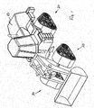
- FIG. 1 four track systems 20 made in accordance to the principles of the present invention are shown mounted to a vehicle 10.
- the vehicle 10 is a front-loader typically used in construction.
- the track systems 20 are used to replace the wheels which are typically used on such vehicle 10.
- Fig. 1 all four track systems 20 are identical though the left and right track systems 20 are mirror image of each other. Still, the front and rear track systems 20 could be different depending, among other things, on the configuration of the vehicle 10. For instance, some farming vehicles (e.g. tractors) sometimes use smaller front track systems and larger rear track systems.
- tractors e.g. tractors
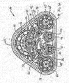
- FIG. 2 and 3A one of the four track systems 20 is shown in greater details.
- the track system 20 comprises a drive wheel 22 configured to be mounted to the axle (not shown) of the vehicle 10.
- the drive wheel 22 defines a rotation axis 23 about which it rotates.
- the drive wheel 22 comprises, along its periphery 24, a plurality of evenly disposed sprocket teeth 26 configured to engage drive lugs (not shown) located on the inner surface 30 of the traction band 28.
- the drive wheel 22 is a sprocket wheel.
- the track system 20 also comprises a frame assembly 34 pivotally mounted to the drive wheel 22. Understandably, though the frame assembly 34 can pivot with respect to the drive wheel 22, the frame assembly 34 does not rotate with the drive wheel 22 as the frame assembly 34 is not drivingly engaged to the drive wheel 22. Though in the present embodiment, the frame assembly 34 is pivotally mounted to the drive wheel 22, in other embodiments, such as the one shown in Fig. 7 , the frame assembly 34 could be configured to be mounted directly to the vehicle 10, typically to its frame. In such embodiments, the frame assembly 34 would typically comprise an attachment frame or assembly 90 configured to secure the frame assembly 34 to the vehicle 10.
- the frame assembly 34 pivotally supports two tandem frames 36 and 38.
- the front tandem frame 36 is pivotally mounted to the frame assembly 34 at front pivoting point 40 while the rear tandem frame 38 is pivotally mounted at rear pivoting point 42.
- the front pivoting point 40 defines a rotation axis 41 while the rear pivoting point 42 defines a rotation axis 43.
- the rotation axis 41 is located longitudinally in front of the drive wheel rotation axis 23 while the rotation axis 43 is located longitudinally behind the drive wheel rotation axis 23.
- the longitudinal distance between the rotation axis 41 and the drive wheel rotation axis 23 is substantially equal to the longitudinal distance between the rotation axis 43 and the drive wheel rotation axis 23. In other embodiments, these two distances could be different.
- the front tandem frame 36 pivotally supports front idler wheels 44 and rear road wheels 46.
- the rear tandem frame 38 pivotally supports rear idler wheels 48 and front road wheels 50.
- the track system 20 also comprises the traction band 28, already introduced above, which is disposed about the drive wheel 22, the idler wheels 44 and 48 and the road wheels 46 and 50.
- the traction band 28 is typically made from reinforced elastomeric material and comprises an inner wheel-engaging surface 30 and an outer ground-engaging surface 32.
- the inner surface 30 of the traction band 28 typically comprises one or more rows of longitudinally aligned drive lugs and/or one or more rows of longitudinally aligned guide lugs (collectively referred to as "inner lugs").
- the drive lugs are configured to be drivingly engaged by the sprocket teeth 26 of the drive wheel 22.
- the inner surface 30 of the traction band 28 could only comprises guide lugs, and thus be devoid of drive lugs, such as to be frictionally engaged by the drive wheel 22 instead of being positively engaged thereby.
- the outer surface 32 of the traction band 28 typically comprises traction lugs configured to engage the terrain over which the track system 20 is operated.
- the front pivoting point 40 allows the front tandem frame 36 to pivot thereabout, allowing the front idler wheels 44 and the rear road wheels 46 to move substantially vertically in opposite directions (e.g. upwardly and downwardly).
- the rear pivoting point 42 allows the rear tandem frame 38 to pivot thereabout, allowing the rear idler wheels 48 and the front road wheels 50 to move substantially vertically in opposite directions (e.g. upwardly and downwardly).
- the ability of the idler wheels 44 and 48 and of the road wheels 46 and 50 to move substantially vertically as the tandem frames 36 and 38 pivot allows the lower run of the traction band 28, i.e. the portion of the traction band 28 which generally engages the ground, to substantially follow the irregularities of the terrain over which the track system 20 is operated.
- the diameter of the idler wheels 44 and 48 is larger than the diameter of the road wheels 46 and 50. Having larger idler wheels 44 and 48 generally allows the track system 20 to more easily overcome obstacles and also to overcome larger obstacles. Larger idler wheels also generally reduce rolling resistance as it is easier to bend an elastomeric traction band around larger idler wheels than around smaller idler wheels.
- the longitudinal distance between the rotation axis 45 of the front idler wheels 44 and the rotation axis 41 of the front pivoting point 40 is smaller than the longitudinal distance between the rotation axis 47 of the rear road wheels 46 and the rotation axis 41 of the front pivoting point 40.
- the longitudinal distance between the rotation axis 49 of the rear idler wheels 48 and the rotation axis 43 of the rear pivoting point 42 is smaller than the longitudinal distance between the rotation axis 51 of the front road wheels 50 and the rotation axis 43 of the rear pivoting point 42.
- the diameter of the idler wheels 44 and 48 is larger than the diameter of the road wheels 46 and 50.
- the present combination of the different longitudinal distances between the rotation axes and of the different wheel diameters generally allows a more balance load distribution between the larger idler wheels 44 and 48 and the smaller road wheels 46 and 50.
- the smaller road wheels 46 and 50 have a load bearing capacity which is generally inferior to the load bearing capacity of the larger diameter idler wheels 44 and 48.
- the load bearing capacity of a wheel will be generally proportional to its diameter. Hence, a wheel with a diameter twice as large as the diameter of another wheel would be able to support approximately twice the load.
- the ratio of the longitudinal distance between the rotation axis of the road wheels and the rotation axis of the tandem frame, to the longitudinal distance between the rotation axis of the idler wheels and the rotation axis of the tandem frame should be approximately equal to the ratio of the diameter of the idler wheels to the diameter of the road wheels.
- wheel width could affect the relation between the longitudinal distances and the wheel diameters.
- wheel diameters could affect the relation between the longitudinal distances and the wheel diameters.
- the longitudinal distance between the rotation axis 51 of the front road wheels 50 and the rotation axis 43 of the rear pivoting point 42 is larger than the longitudinal distance between the rotation axis 49 of the rear idler wheels 48 and the rotation axis 43 of the rear pivoting point 42, the downward motion of the front road wheels 50 will be countered, thereby limiting the upward motion of the rear idler wheels 48 and thus limiting the overall pivotal movement of the rear tandem frame 38.
- the longer longitudinal distance between the rotation axis 51 of the front road wheels 50 and the rotation axis 43 of the rear pivoting point 42 creates a longer lever arm which can more easily counter the downward motion.
- limiting the rotation of the rear tandem frame 38 with respect to the pivoting point 42 is beneficial as it generally reduces lag time during direction switching and as it generally provides a more stable operation of the track system 20, and thus a more stable operation of the vehicle 10. Understandably, when the vehicle 10 is operated in reverse, the same principles apply to the front tandem frame 36 and its associated front idler wheels 44 and rear road wheels 46.
- the rotation axis 51 of the front road wheels 50 is located longitudinally in front of the rotation axis 23 of the drive wheel 22.
- the rotation axis 47 of the rear road wheels 46 is located longitudinally behind the rotation axis 23 of the drive wheel 22.
- the center of gravity of the traction system 20 is substantially vertically aligned with the rotation axis 23 of the drive wheel 22. Understandably, the relative position of the rotation axes of the idler wheels, of the road wheels and of the pivoting points with respect to the rotation axis 23 of the drive wheel 22 can further improve the load distribution and the load transfer between the idler wheels and road wheels during operation of the track system 20.
- the frame assembly 34 comprises frame members 52, 54 and 56 between which are mounted blockers or limiters 53 and 55. While the frame member 52 is located on the outer or outboard side of the drive wheel 22, the frame members 54 and 56, are located on the inner or inboard side of the drive wheel 22. Understandably, the frame assembly 34 normally behaves as a unitary structure. For their part, the limiters 53 and 55 limit the amplitude of the pivotal movements of the tandem frames 36 and 38 with respect to the frame assembly 34.
- FIG. 5 and 6 another embodiment of a track system 120 made in accordance with the principles of the present invention is shown.
- the track system 120 is broadly similar to track system 20 and therefore generally comprises a drive wheel 122, a frame assembly 134 pivotally mounted to the drive wheel 122, a front tandem frame 136 pivotally mounted to the frame assembly 134, a rear tandem frame 138 pivotally mounted to the frame assembly 134.
- the rear tandem frame 138 differs from the rear tandem frame 38 in that it further pivotally supports a tandem sub-frame 160 where the rear tandem frame 138 pivotally supports the front road wheels 150.
- tandem sub-frame 160 pivotally supports two sets of front road wheels 150, front road wheels 150A and front road wheels 150B. In other embodiments, there could be more than two sets of front road wheels 150.
- the additional set or sets of road wheels can be used to support larger loads (e.g. heavier vehicles) and/or to provide a smoother ride.
- the additional set or sets of road wheels can also be beneficial when a longer track system is needed (e.g. for improved stability).
- the rear road wheels 146 could also be replaced by two or more sets of road wheels 146A and 146B mounted to a rear tandem sub-frame (not shown).
- FIG. 8 and 9 another embodiment of a track system 220 made in accordance with the principles of the present invention is shown.
- the track system 220 differs from track systems 20 and 120 in that the front and rear tandem frames 236 and 238 are not directly overlapping. However, track system 220 comprises at least one additional intermediate tandem frame 270, pivotally mounted to the support frame assembly 234 at 272, which overlaps both the front and rear tandem frames 236 and 238.
- intermediate tandem frame 270 may be beneficial when, for example, longer track systems are required.
- the front and rear tandem frames may not directly overlap.
- adjacent tandem frames should generally be overlapping.
- the intermediate tandem frame 270 further supports a tandem sub-frame 280, similar to the tandem sub-frame 160 of the embodiment of Figs. 5 and 6 .
- the tandem sub-frame 280 pivotally supports two sets of road wheels 282, road wheels 282A and 282B.
- the front, rear and intermediate tandem frames 236, 238 and 270 could all pivotally support tandem sub-frames if appropriate.
- front and rear qualifiers used hereinabove are relative to the typically normal direction of movement of the track systems 20, 120 and 220 and have been use for ease of reference.
- front and rear qualifiers should not be construed limitatively.
Landscapes
- Engineering & Computer Science (AREA)
- Chemical & Material Sciences (AREA)
- Combustion & Propulsion (AREA)
- Transportation (AREA)
- Mechanical Engineering (AREA)
- Arrangement And Driving Of Transmission Devices (AREA)
- Platform Screen Doors And Railroad Systems (AREA)
- Tires In General (AREA)
Description
- The present patent application claims the benefits of priority of
U.S. Provisional Patent Application No. 61/559,290 - The present invention generally relates to track systems and traction assemblies used as wheel replacement for typically wheeled vehicles. More particularly, the present invention relates to track systems and traction assemblies for use on heavy vehicles such as, but not limited to, farming and agricultural vehicles (e.g. tractors, harvesters, etc.) and construction and industrial vehicles (e.g. excavators, combines, forestry equipments, etc.).
- Several normally wheeled vehicles and particularly heavy wheeled vehicles (e.g. farming tractors, front loaders, harvesters, etc.) often have their wheels replaced by track systems which use an endless traction band instead of a tire for propulsion. Vehicles equipped with track systems typically have improved floatation and traction, particularly when they are operated over soft terrains.
- However, during operation, some components of the track systems, and more particularly the idler wheels and road wheels, can experience uneven load distribution. This is particularly true when the idler wheels and the road wheels are mounted in tandem on tandem frames.
- Indeed, in such track systems, the resultant force from the traction band tension and the traction band friction can induce a torque around the tandem frame pivot, resulting in the rotation of the tandem frame thereabout. This rotation then generally causes the wheels located at one end of the tandem frame to move upwardly while causing the wheels located at the other end of the tandem frame to move downwardly, resulting in an increased load on the wheels which are urged downwardly. The rotation of the tandem frame can also cause the trailing portion of the track system to rise. This uneven load distribution can reduce the efficiency of the track system and even lead to premature failure thereof.
- Furthermore, when the vehicle equipped with such track systems needs to frequently switch from moving in a forward direction to moving in a rearward direction, and vice-versa, there is often an unpleasant lag time before the track systems properly respond to the change in moving direction. This lag time is at least partially caused by the time it takes for the tandem frames to pivot back to their normal position and then to their new pivoted position. This lag time causes, among other things, unwanted delays in the operation of the vehicle.
-
U.S. Patent No. 5,842,757 , describing the preamble of claim 1, discloses such a typical track system comprising tandem frames for supporting the idler wheels and road wheels. - Hence, there is a need for an improved track system which mitigates at least some shortcomings of prior art track systems.
- A track system in accordance with the principles of the present invention as defined by independent claim 1 generally mitigates at least some of the shortcomings of prior track systems by having the idler wheels and the road wheels mounted on overlapping tandem frames.
- Hence, a track system in accordance with the principles of the present invention generally comprises a drive wheel configured to be mounted to an axle of a vehicle, a support frame (or support frame assembly) configured to be mounted to the vehicle, front and rear idler wheels, typically respectively mounted at the front and at the rear of the track system, road wheels, typically mounted longitudinally between the idler wheels, and an endless traction band disposed about the drive wheel, the idler wheels and the road wheels.
- The idler wheels and the road wheels are pivotally mounted to tandem frames which are pivotally mounted to the support frame at longitudinally spaced apart pivoting points. The tandem frames allow the idler wheels and the road wheels to move or pivot with respect to the pivoting points, thereby allowing the traction band, and more particularly the lower run thereof, to generally follow the irregularities of the terrain over which the track system is operated.
- In accordance with the principles of the present invention, adjacent tandem frames are overlapping, i.e. the tandem frames extend into one another. Due to the overlapping configuration of the tandem frames, the movements of the idler wheels and/or of the road wheels with respect to the pivoting points are limited.
- In typical though non-limitative embodiments of a track system in accordance with the principles of the present invention, the diameter of the idler wheels is larger than the diameter of the road wheels. In such embodiments, when a tandem frame support both idler wheels and road wheels, the longitudinal distance between the rotation axis of the idler wheels and the rotation axis of the pivoting point of the tandem frame is typically smaller than the longitudinal distance between the rotation axis of the road wheels and the rotation axis of the pivoting point of the tandem frame. When a tandem frame supports only road wheels, the longitudinal distances between the rotation axes of the road wheels and the rotation axis of the pivoting point of the tandem frame is typically substantially equal.
- In typical though non-limitative embodiments of a track system in accordance with the principles of the present invention, the rotation axes of the pivoting points of the tandem frames which respectively support the front and rear idler wheels are respectively located longitudinally in front of and behind the rotation axis of the drive wheel.
- In some non-limitative embodiments of a track system in accordance with the principles of the present invention, at least some of the road wheels are pivotally mounted to at least one tandem sub-frame, the at least one tandem sub-frame being pivotally mounted to one of the tandem frames.
- A track system in accordance with the principles of the present invention generally improves the load distributions between the idler wheels and the road wheels, and/or generally decreases the tendency of the pivoting point located behind the rotation axis of the drive wheel to move upwardly when the vehicle moves forwardly, and vice-versa, and/or generally reduces the lag time when the vehicle moving in a forward direction switches to move in a rearward direction, and vice-versa.
- Other and further aspects and advantages of the present invention will be obvious upon an understanding of the illustrative embodiments about to be described or will be indicated in the appended claims, and various advantages not referred to herein will occur to one skilled in the art upon employment of the invention in practice. The features of the present invention which are believed to be novel are set forth with particularity in the appended claims.
- The above and other aspects, features and advantages of the invention will become more readily apparent from the following description, reference being made to the accompanying drawings in which:
-
Figure 1 is a perspective view of a vehicle having mounted thereto four track systems in accordance with the principles to the present invention. -
Figure 2 is a perspective view of one of the track system ofFig. 1 . -
Figure 3A is a side view of the track system ofFig. 2 . -
Figure 3B is a side view of the track system ofFig. 2 . -
Figure 4 is an exploded perspective view of the track system ofFig. 2 , without the endless traction band. -
Figure 5 is a perspective view of another embodiment of a track system in accordance with the principles to the present invention, without the endless traction band. -
Figure 6 is a side view of the track system ofFig. 5 . -
Figure 7 is a perspective view of a variant of the track system ofFig. 2 , viewed from the inboard side. -
Figure 8 is a perspective view of another embodiment of a track system in accordance with the principles to the present invention, without the endless traction band. -
Figure 9 is a side view of the track system ofFig. 8 . - A novel track system with overlapping wheel tandem frames will be described hereinafter. Although the invention is described in terms of specific illustrative embodiments, it is to be understood that the embodiments described herein are by way of example only and that the scope of the invention is not intended to be limited thereby.
- Referring first to
Fig. 1 , fourtrack systems 20 made in accordance to the principles of the present invention are shown mounted to a vehicle 10. InFig. 1 , the vehicle 10 is a front-loader typically used in construction. Notably, inFig. 1 , thetrack systems 20 are used to replace the wheels which are typically used on such vehicle 10. - In
Fig. 1 , all fourtrack systems 20 are identical though the left andright track systems 20 are mirror image of each other. Still, the front andrear track systems 20 could be different depending, among other things, on the configuration of the vehicle 10. For instance, some farming vehicles (e.g. tractors) sometimes use smaller front track systems and larger rear track systems. - Referring now to
Figs. 2 and3A , one of the fourtrack systems 20 is shown in greater details. - In the present embodiment, the
track system 20 comprises adrive wheel 22 configured to be mounted to the axle (not shown) of the vehicle 10. Thedrive wheel 22 defines arotation axis 23 about which it rotates. Thedrive wheel 22 comprises, along itsperiphery 24, a plurality of evenly disposedsprocket teeth 26 configured to engage drive lugs (not shown) located on theinner surface 30 of thetraction band 28. In the present embodiment, thedrive wheel 22 is a sprocket wheel. - The
track system 20 also comprises aframe assembly 34 pivotally mounted to thedrive wheel 22. Understandably, though theframe assembly 34 can pivot with respect to thedrive wheel 22, theframe assembly 34 does not rotate with thedrive wheel 22 as theframe assembly 34 is not drivingly engaged to thedrive wheel 22. Though in the present embodiment, theframe assembly 34 is pivotally mounted to thedrive wheel 22, in other embodiments, such as the one shown inFig. 7 , theframe assembly 34 could be configured to be mounted directly to the vehicle 10, typically to its frame. In such embodiments, theframe assembly 34 would typically comprise an attachment frame orassembly 90 configured to secure theframe assembly 34 to the vehicle 10. - In the present embodiment, the
frame assembly 34 pivotally supports twotandem frames front tandem frame 36 is pivotally mounted to theframe assembly 34 at front pivoting point 40 while therear tandem frame 38 is pivotally mounted atrear pivoting point 42. - The front pivoting point 40 defines a
rotation axis 41 while therear pivoting point 42 defines arotation axis 43. As best shown inFig. 3A , in the present embodiment, therotation axis 41 is located longitudinally in front of the drivewheel rotation axis 23 while therotation axis 43 is located longitudinally behind the drivewheel rotation axis 23. - In the present embodiment, the longitudinal distance between the
rotation axis 41 and the drivewheel rotation axis 23 is substantially equal to the longitudinal distance between therotation axis 43 and the drivewheel rotation axis 23. In other embodiments, these two distances could be different. - Referring back to
Figs. 2 and3A , in the present embodiment, thefront tandem frame 36 pivotally supports frontidler wheels 44 andrear road wheels 46. In a substantially symmetrical fashion, therear tandem frame 38 pivotally supports rearidler wheels 48 andfront road wheels 50. - The
track system 20 also comprises thetraction band 28, already introduced above, which is disposed about thedrive wheel 22, theidler wheels road wheels traction band 28 is typically made from reinforced elastomeric material and comprises an inner wheel-engagingsurface 30 and an outer ground-engagingsurface 32. - Though not shown in the figures, the
inner surface 30 of thetraction band 28 typically comprises one or more rows of longitudinally aligned drive lugs and/or one or more rows of longitudinally aligned guide lugs (collectively referred to as "inner lugs"). The drive lugs are configured to be drivingly engaged by thesprocket teeth 26 of thedrive wheel 22. - In other embodiments, the
inner surface 30 of thetraction band 28 could only comprises guide lugs, and thus be devoid of drive lugs, such as to be frictionally engaged by thedrive wheel 22 instead of being positively engaged thereby. - Though not shown in the figures, the
outer surface 32 of thetraction band 28 typically comprises traction lugs configured to engage the terrain over which thetrack system 20 is operated. - Referring now more particularly to
Fig. 3A , the front pivoting point 40 allows thefront tandem frame 36 to pivot thereabout, allowing the frontidler wheels 44 and therear road wheels 46 to move substantially vertically in opposite directions (e.g. upwardly and downwardly). Similarly, therear pivoting point 42 allows therear tandem frame 38 to pivot thereabout, allowing therear idler wheels 48 and thefront road wheels 50 to move substantially vertically in opposite directions (e.g. upwardly and downwardly). The ability of theidler wheels road wheels traction band 28, i.e. the portion of thetraction band 28 which generally engages the ground, to substantially follow the irregularities of the terrain over which thetrack system 20 is operated. - Still referring to
Fig. 3A , in the present embodiment, the diameter of theidler wheels road wheels idler wheels track system 20 to more easily overcome obstacles and also to overcome larger obstacles. Larger idler wheels also generally reduce rolling resistance as it is easier to bend an elastomeric traction band around larger idler wheels than around smaller idler wheels. - In addition, in the present embodiment, the longitudinal distance between the
rotation axis 45 of the frontidler wheels 44 and therotation axis 41 of the front pivoting point 40 is smaller than the longitudinal distance between therotation axis 47 of therear road wheels 46 and therotation axis 41 of the front pivoting point 40. Similarly, the longitudinal distance between the rotation axis 49 of therear idler wheels 48 and therotation axis 43 of therear pivoting point 42 is smaller than the longitudinal distance between the rotation axis 51 of thefront road wheels 50 and therotation axis 43 of therear pivoting point 42. - As already mentioned above, the diameter of the
idler wheels road wheels larger idler wheels smaller road wheels smaller road wheels idler wheels road wheels inner surface 30 of theelastomeric traction band 28, it is preferable to more evenly balance the load transmitted to and/or supported by theidler wheels road wheels track system 20. - Typically, the load bearing capacity of a wheel will be generally proportional to its diameter. Hence, a wheel with a diameter twice as large as the diameter of another wheel would be able to support approximately twice the load.
- Thus, to generally evenly balance the load distribution between the
idler wheels road wheels - Understandably, other parameters (e.g. wheel width) could affect the relation between the longitudinal distances and the wheel diameters. In addition, one could choose particular distances and/or wheel diameters such as to change the load distribution.
- Referring now to
Fig. 3B , when thetrack system 20 is operated such as to move in a forward direction, indicated by arrow F, thedrive wheel 22 will rotate in a counterclockwise direction as indicated by arrow S. The rotation of thedrive wheel 22 will pull on the portion of thetraction band 28 located behind thedrive wheel 22. This pulling, indicated by arrow T, will impart an upward motion to therear idler wheels 48 as indicated by arrow RI. Because of the pivotal connection of therear tandem frame 38 to theframe assembly 34, the upward motion of therear idler wheels 48 will cause an opposite downward motion of thefront road wheels 50 as indicated by arrow FR. - However, as the longitudinal distance between the rotation axis 51 of the
front road wheels 50 and therotation axis 43 of therear pivoting point 42 is larger than the longitudinal distance between the rotation axis 49 of therear idler wheels 48 and therotation axis 43 of therear pivoting point 42, the downward motion of thefront road wheels 50 will be countered, thereby limiting the upward motion of therear idler wheels 48 and thus limiting the overall pivotal movement of therear tandem frame 38. Indeed, the longer longitudinal distance between the rotation axis 51 of thefront road wheels 50 and therotation axis 43 of therear pivoting point 42 creates a longer lever arm which can more easily counter the downward motion. - Furthermore, if the
track system 20 then switches to be operated such as to move in a rearward direction, thedrive wheel 22 will then rotate in a clockwise direction and the situation ofFig. 3B will be essentially reversed. However, as the pivotal motion of therear tandem frame 38 was previously limited, the time required to pivot therear tandem frame 38 back to its normal position will be reduced, thereby reducing the lag time when thetrack system 20 switches from moving in a forward direction to moving in a rearward direction, and vice-versa. - Understandably, frequent direction switching of the
track system 20 can occur when thetrack system 20 is mounted to a vehicle, such as the front-loader shown inFig. 1 , which frequently switches direction during, for example, the handling of material. - Hence, limiting the rotation of the
rear tandem frame 38 with respect to thepivoting point 42 is beneficial as it generally reduces lag time during direction switching and as it generally provides a more stable operation of thetrack system 20, and thus a more stable operation of the vehicle 10. Understandably, when the vehicle 10 is operated in reverse, the same principles apply to thefront tandem frame 36 and its associated frontidler wheels 44 andrear road wheels 46. - In the present embodiment, the rotation axis 51 of the
front road wheels 50 is located longitudinally in front of therotation axis 23 of thedrive wheel 22. Symmetrically, therotation axis 47 of therear road wheels 46 is located longitudinally behind therotation axis 23 of thedrive wheel 22. In addition, in the present embodiment, the center of gravity of thetraction system 20 is substantially vertically aligned with therotation axis 23 of thedrive wheel 22. Understandably, the relative position of the rotation axes of the idler wheels, of the road wheels and of the pivoting points with respect to therotation axis 23 of thedrive wheel 22 can further improve the load distribution and the load transfer between the idler wheels and road wheels during operation of thetrack system 20. - Referring now to
Fig. 4 , an exploded view of thetrack system 20, without thetraction band 28 is shown. Notably, in the present embodiment, theframe assembly 34 comprisesframe members frame member 52 is located on the outer or outboard side of thedrive wheel 22, theframe members drive wheel 22. Understandably, theframe assembly 34 normally behaves as a unitary structure. For their part, the limiters 53 and 55 limit the amplitude of the pivotal movements of the tandem frames 36 and 38 with respect to theframe assembly 34. - Referring now to
Figs. 5 and6 , another embodiment of atrack system 120 made in accordance with the principles of the present invention is shown. - The
track system 120 is broadly similar to tracksystem 20 and therefore generally comprises adrive wheel 122, aframe assembly 134 pivotally mounted to thedrive wheel 122, afront tandem frame 136 pivotally mounted to theframe assembly 134, a rear tandem frame 138 pivotally mounted to theframe assembly 134. - However, though the
front tandem frame 136 is similar to thefront tandem frame 36 in that it supports the frontidler wheels 144 and therear road wheels 146, the rear tandem frame 138 differs from therear tandem frame 38 in that it further pivotally supports atandem sub-frame 160 where the rear tandem frame 138 pivotally supports the front road wheels 150. - As best shown in
Fig. 6 , thetandem sub-frame 160 pivotally supports two sets of front road wheels 150,front road wheels 150A and front road wheels 150B. In other embodiments, there could be more than two sets of front road wheels 150. - The additional set or sets of road wheels can be used to support larger loads (e.g. heavier vehicles) and/or to provide a smoother ride. The additional set or sets of road wheels can also be beneficial when a longer track system is needed (e.g. for improved stability).
- Understandably, depending on the exact configuration of the
track system 120, therear road wheels 146 could also be replaced by two or more sets of road wheels 146A and 146B mounted to a rear tandem sub-frame (not shown). - Referring to
Figs. 8 and9 , another embodiment of atrack system 220 made in accordance with the principles of the present invention is shown. - The
track system 220 differs fromtrack systems track system 220 comprises at least one additionalintermediate tandem frame 270, pivotally mounted to thesupport frame assembly 234 at 272, which overlaps both the front and rear tandem frames 236 and 238. - Having one or more overlapping intermediate tandem frames, such as
intermediate tandem frame 270, may be beneficial when, for example, longer track systems are required. - Understandably, as shown in
track system 220, when more than two tandem frames are present, the front and rear tandem frames may not directly overlap. However, in accordance with the principles of the present invention and as shown intrack system 220, when more than two tandem frames are present, adjacent tandem frames should generally be overlapping. - Still referring to
Figs. 8 and9 , in this embodiment, theintermediate tandem frame 270 further supports atandem sub-frame 280, similar to thetandem sub-frame 160 of the embodiment ofFigs. 5 and6 . Thetandem sub-frame 280 pivotally supports two sets of road wheels 282,road wheels - Understandably, depending on the exact configuration of the
track system 220, the front, rear and intermediate tandem frames 236, 238 and 270 could all pivotally support tandem sub-frames if appropriate. - Understandably, the front and rear qualifiers used hereinabove are relative to the typically normal direction of movement of the
track systems - While illustrative and presently preferred embodiments of the invention have been described in detail hereinabove, it is to be understood that the inventive concepts may be otherwise variously embodied and employed and that the appended claims are intended to be construed to include such variations except insofar as limited by the prior art.
Claims (17)
- A track system (20, 120, 220) for a vehicle (10), the track system (20, 120, 220) comprising:a) a drive wheel (22, 122) configured to be mounted to the vehicle (10), the drive wheel (22, 122) having a drive wheel rotation axis (23);b) a support frame (34, 134, 234);c) a plurality of tandem frames (36, 38, 136, 138, 236, 238, 270) pivotally mounted to the support frame (34, 134, 234), each of the tandem frames (36, 38, 136, 138, 236, 238, 270) having a tandem frame rotation axis (41, 43), the tandem frames (36, 38, 136, 138, 236, 238, 270) comprising at least a first tandem frame (36, 136, 236) pivotally supporting at least one first idler wheel (44, 144) and at least one first road wheel (46, 146), and a second tandem frame (38, 138, 238) pivotally supporting at least one second idler wheel (48, 148) and at least one second road wheel (50, 150);d) a traction band (28) disposed about the drive wheel (22, 122), the at least one first idler wheel (44, 144), the at least one second idler wheel (48, 148), the at least one first road wheel (46, 146), and the at least one second road wheel (50, 150);
characterized in that adjacent tandem frames (36, 38, 136, 138, 236, 238, 270) are overlapping whereby the at least one first road wheel (46, 146) is located longitudinally between the wheels pivotally supported by the tandem frame (38, 138, 238, 270) adjacent to the first tandem frame (36, 136, 236), and whereby said at least one second road wheel (50, 150) is located longitudinally between the wheels pivotally supported by the tandem frame (36, 136, 236, 270) adjacent to the second tandem frame (38, 138, 238). - A track system as claimed in claim 1, wherein the tandem frame rotation axes (41, 43) are longitudinally spaced apart.
- A track system as claimed in claim 2, wherein the drive wheel rotation axis (23) is located longitudinally between the first tandem frame rotation axis (41) and the second tandem frame rotation axis (43).
- A track system as claimed in claim 1, wherein the at least one first idler wheel (44, 144) has a first idler wheel rotation axis (45), and wherein the at least one first road wheel (46, 146) has a first road wheel rotation axis (47).
- A track system as claimed in claim 4, wherein a longitudinal distance between the first idler wheel rotation axis (45) and the first tandem frame rotation axis (41) is smaller than a longitudinal distance between the first tandem frame rotation axis (41) and the first road wheel rotation axis (47).
- A track system as claimed in claim 5, wherein the at least one first idler wheel (44, 144) has a first idler wheel diameter, and wherein the at least one first road wheel (46, 146) has a first road wheel diameter, the first idler wheel diameter being larger than the first road wheel diameter.
- A track system as claimed in any of claims 1 to 6, wherein the at least one second idler wheel (48, 148) has a second idler wheel rotation axis (49), and wherein the at least one second road wheel (50, 150) has a second road wheel rotation axis (51).
- A track system as claimed in claim 7, wherein a longitudinal distance between the second idler wheel rotation axis (49) and the second tandem frame rotation axis (43) is smaller than a longitudinal distance between the second tandem frame rotation axis (43) and the second road wheel rotation axis (51).
- A track system as claimed in claim 8, wherein the at least one second idler wheel (48) has a second idler wheel diameter, and wherein the at least one second road wheel (50) has a second road wheel diameter, the second idler wheel diameter being larger than the second road wheel diameter.
- A track system as claimed in any of claims 1 to 9, wherein the tandem frames (36, 38, 136, 138, 236, 238, 270) comprise at least a third tandem frame (270) pivotally supporting at least one third road wheel and at least one fourth road wheel.
- A track system as claimed in claim 10, wherein the third tandem frame rotation axis is located longitudinally between the first tandem frame rotation axis (41) and the second tandem frame rotation axis (43).
- A track system as claimed in any of claims 1 to 11, wherein the at least one first idler wheel (44, 144) comprises a plurality of first idler wheels (44, 144), wherein the at least one first road wheel (46, 146) comprises a plurality of first road wheels (46, 146), wherein the at least one second idler wheel (48, 148) comprises a plurality of second idler wheels (48, 148), and wherein the at least one second road wheel (50, 150) comprises a plurality of second road wheels (50, 150).
- A track system as claimed in any of claims 1 to 12, wherein at least one of the tandem frames (36, 38, 136, 138, 236, 238, 270) comprises at least one tandem sub-frame (160, 280) pivotally mounted to the at least one of the tandem frames (36, 38, 136, 138, 236, 238, 270), the at least one tandem sub-frame (160, 280) pivotally supporting at least two road wheels (150, 282).
- A track system as claimed in any of claims 1to 13, wherein the support frame (34, 134, 234) is pivotally mounted to the drive wheel (22, 122).
- A track system as claimed in any of claims 1to 13, wherein the support frame (34, 134, 234) is configured to be mounted to the vehicle (10).
- A track system as claimed in any of claims 1 to 15, wherein the first tandem frame (36, 136) is the front tandem frame (36, 136), wherein the second tandem frame (38, 138) is the rear tandem frame (38, 138), wherein the at least one first idler wheel (44, 144) is the at least one front idler wheel (44, 144), and wherein the at least one second idler wheel (48, 148) is the at least one rear idler wheel (48, 148).
- A vehicle (10) having mounted thereto at least one track system (20, 120, 220) as
claimed in any of claims 1 to 18.
Applications Claiming Priority (1)
| Application Number | Priority Date | Filing Date | Title |
|---|---|---|---|
| US201161559290P | 2011-11-14 | 2011-11-14 |
Publications (3)
| Publication Number | Publication Date |
|---|---|
| EP2591990A2 EP2591990A2 (en) | 2013-05-15 |
| EP2591990A3 EP2591990A3 (en) | 2013-09-25 |
| EP2591990B1 true EP2591990B1 (en) | 2014-08-13 |
Family
ID=47227584
Family Applications (1)
| Application Number | Title | Priority Date | Filing Date |
|---|---|---|---|
| EP12192506.9A Active EP2591990B1 (en) | 2011-11-14 | 2012-11-14 | Track system with overlapping wheel tandem frames |
Country Status (3)
| Country | Link |
|---|---|
| US (1) | US9308951B2 (en) |
| EP (1) | EP2591990B1 (en) |
| CA (1) | CA2796144C (en) |
Families Citing this family (16)
| Publication number | Priority date | Publication date | Assignee | Title |
|---|---|---|---|---|
| US10640160B2 (en) | 2014-09-29 | 2020-05-05 | Soucy International Inc. | Progressive damping system for a track system |
| US10668962B2 (en) | 2014-09-29 | 2020-06-02 | Soucy International Inc. | Track system |
| US10526027B2 (en) | 2014-09-29 | 2020-01-07 | Soucy International Inc. | Damping system for an endless track system |
| US10633044B2 (en) | 2014-09-29 | 2020-04-28 | Soucy International Inc. | Dynamic tensioner locking device for a track system and method thereof |
| CA2962801C (en) | 2014-09-29 | 2021-08-24 | Soucy International Inc. | Track system having low vibrations |
| US10065690B2 (en) * | 2015-04-03 | 2018-09-04 | Harris Corporation | Conformal suspension for unmanned ground vehicle |
| CA2983921C (en) | 2015-04-29 | 2023-09-26 | Clark Equipment Company | Apparatus for mounting a track frame to a frame of a power machine |
| CN105059408B (en) * | 2015-08-03 | 2017-12-26 | 中国矿业大学 | The crawler-type mobile platform of passive adaptation landform and there is its robot |
| DE202015007844U1 (en) * | 2015-11-12 | 2016-11-15 | Street-Rubbers GmbH & Co. KG | Working machine, in particular wheeled excavator |
| FR3043997B1 (en) * | 2015-11-24 | 2018-07-27 | Manitou Bf | HANDLING VEHICLE |
| US11208162B2 (en) * | 2016-06-22 | 2021-12-28 | Soucy International Inc. | Track system |
| US10399618B2 (en) * | 2017-01-25 | 2019-09-03 | Altoz, Inc. | Track assembly for a vehicle |
| EP3606807B1 (en) * | 2017-04-07 | 2022-02-16 | Soucy International Inc. | Track system |
| US10933929B1 (en) | 2017-11-20 | 2021-03-02 | Soucy International Inc. | Track system for a vehicle |
| US11618515B2 (en) * | 2019-04-09 | 2023-04-04 | Cnh Industrial America Llc | Suspension system for a track-driven work vehicle with tandem rear idler/roller |
| US20220055699A1 (en) * | 2020-08-18 | 2022-02-24 | Camso Inc. | Monitoring of track system for traction of a vehicle |
Family Cites Families (11)
| Publication number | Priority date | Publication date | Assignee | Title |
|---|---|---|---|---|
| US3170532A (en) * | 1963-07-08 | 1965-02-23 | Garrett Corp | Effective weight-increasing device for track-laying vehicles |
| US3841424A (en) * | 1971-12-27 | 1974-10-15 | Caterpillar Tractor Co | Triangular track resilient bogie suspension |
| US3826325A (en) * | 1972-08-22 | 1974-07-30 | Caterpillar Tractor Co | Track suspension assembly |
| US4537267A (en) * | 1983-12-20 | 1985-08-27 | Caterpillar Tractor Co. | Belt tensioning mechanism |
| DE4335657A1 (en) * | 1993-10-14 | 1995-04-20 | Claas Ohg | Caterpillar drive |
| US5373909A (en) * | 1993-10-26 | 1994-12-20 | Byron Enterprises, Inc. | Tracked vehicles and power drive apparatus for motivating tracked vehicles |
| US5494125A (en) * | 1994-08-19 | 1996-02-27 | Caterpillar Paving Products Inc. | Track supporting roller apparatus |
| US5842757A (en) * | 1997-01-31 | 1998-12-01 | Agtracks, Inc. | Track system for vehicles |
| CA2209022C (en) * | 1997-07-18 | 1999-02-09 | Guy Gignac | Hydrostatic transmission caterpillar tread |
| US6249994B1 (en) * | 1999-12-16 | 2001-06-26 | Caterpillar Inc. | Apparatus and method for operating track tensioning assembly of a hydraulic excavator |
| US8083242B2 (en) * | 2007-02-15 | 2011-12-27 | Glen Brazier | Multi-pivot vehicle suspension |
-
2012
- 2012-11-13 US US13/675,039 patent/US9308951B2/en active Active
- 2012-11-13 CA CA2796144A patent/CA2796144C/en active Active
- 2012-11-14 EP EP12192506.9A patent/EP2591990B1/en active Active
Also Published As
| Publication number | Publication date |
|---|---|
| EP2591990A2 (en) | 2013-05-15 |
| CA2796144C (en) | 2019-04-30 |
| CA2796144A1 (en) | 2013-05-14 |
| US9308951B2 (en) | 2016-04-12 |
| US20130119753A1 (en) | 2013-05-16 |
| EP2591990A3 (en) | 2013-09-25 |
Similar Documents
| Publication | Publication Date | Title |
|---|---|---|
| CA2796144C (en) | Track system with overlapping wheel tandem frames | |
| EP3371038B1 (en) | Tracked vehicle with articulating frame | |
| US8632138B2 (en) | Traction assembly | |
| EP2081814B1 (en) | Conformable track assembly for a robotic crawler | |
| AU2013251212B2 (en) | Track suspension | |
| EP3259176B1 (en) | Track-module apparatus with load-independent load distribution | |
| US9033430B2 (en) | Track assembly for an all-terrain vehicle (ATV) or other tracked vehicle | |
| US9051009B2 (en) | Steerable track system | |
| US20120242142A1 (en) | Track Assembly for Traction of a Vehicle | |
| EP3165432B1 (en) | Track system slack adjuster for tracked vehicle | |
| CA2655592A1 (en) | Endless belt drive for vehicle | |
| CA2878283A1 (en) | Suspension and lock-out systems for a tracked vehicle | |
| CA2757049A1 (en) | Traction system for a vehicle | |
| US20150183464A1 (en) | Torsional Suspensioned, Steerable, Oscillating and Propelling Axle Assembly | |
| US20200148290A1 (en) | Endless Track System Suspension | |
| CA3100402C (en) | Tandem walking beam suspension system for a track-mounted vehicle | |
| US20250360977A1 (en) | Support structure for connecting at least one support wheel assembly to a frame of a track system and track system having the same | |
| US20200339200A1 (en) | Guard assembly and vehicle having same | |
| US20230331320A1 (en) | Pivoting assembly and track system comprising same | |
| US20250340257A1 (en) | Track system and wheel assemblies for track systems | |
| US11618515B2 (en) | Suspension system for a track-driven work vehicle with tandem rear idler/roller | |
| CA2495642A1 (en) | Traction assembly for a vehicle |
Legal Events
| Date | Code | Title | Description |
|---|---|---|---|
| PUAI | Public reference made under article 153(3) epc to a published international application that has entered the european phase |
Free format text: ORIGINAL CODE: 0009012 |
|
| AK | Designated contracting states |
Kind code of ref document: A2 Designated state(s): AL AT BE BG CH CY CZ DE DK EE ES FI FR GB GR HR HU IE IS IT LI LT LU LV MC MK MT NL NO PL PT RO RS SE SI SK SM TR |
|
| AX | Request for extension of the european patent |
Extension state: BA ME |
|
| PUAL | Search report despatched |
Free format text: ORIGINAL CODE: 0009013 |
|
| AK | Designated contracting states |
Kind code of ref document: A3 Designated state(s): AL AT BE BG CH CY CZ DE DK EE ES FI FR GB GR HR HU IE IS IT LI LT LU LV MC MK MT NL NO PL PT RO RS SE SI SK SM TR |
|
| AX | Request for extension of the european patent |
Extension state: BA ME |
|
| RIC1 | Information provided on ipc code assigned before grant |
Ipc: B62D 55/04 20060101AFI20130822BHEP Ipc: B62D 55/065 20060101ALI20130822BHEP Ipc: B62D 55/14 20060101ALI20130822BHEP Ipc: B62D 55/084 20060101ALI20130822BHEP |
|
| 17P | Request for examination filed |
Effective date: 20140307 |
|
| RBV | Designated contracting states (corrected) |
Designated state(s): AL AT BE BG CH CY CZ DE DK EE ES FI FR GB GR HR HU IE IS IT LI LT LU LV MC MK MT NL NO PL PT RO RS SE SI SK SM TR |
|
| GRAP | Despatch of communication of intention to grant a patent |
Free format text: ORIGINAL CODE: EPIDOSNIGR1 |
|
| INTG | Intention to grant announced |
Effective date: 20140506 |
|
| GRAS | Grant fee paid |
Free format text: ORIGINAL CODE: EPIDOSNIGR3 |
|
| GRAA | (expected) grant |
Free format text: ORIGINAL CODE: 0009210 |
|
| AK | Designated contracting states |
Kind code of ref document: B1 Designated state(s): AL AT BE BG CH CY CZ DE DK EE ES FI FR GB GR HR HU IE IS IT LI LT LU LV MC MK MT NL NO PL PT RO RS SE SI SK SM TR |
|
| REG | Reference to a national code |
Ref country code: GB Ref legal event code: FG4D |
|
| REG | Reference to a national code |
Ref country code: CH Ref legal event code: EP Ref country code: AT Ref legal event code: REF Ref document number: 682028 Country of ref document: AT Kind code of ref document: T Effective date: 20140815 |
|
| REG | Reference to a national code |
Ref country code: IE Ref legal event code: FG4D |
|
| REG | Reference to a national code |
Ref country code: DE Ref legal event code: R096 Ref document number: 602012002736 Country of ref document: DE Effective date: 20140925 |
|
| REG | Reference to a national code |
Ref country code: NL Ref legal event code: T3 |
|
| REG | Reference to a national code |
Ref country code: AT Ref legal event code: MK05 Ref document number: 682028 Country of ref document: AT Kind code of ref document: T Effective date: 20140813 |
|
| REG | Reference to a national code |
Ref country code: LT Ref legal event code: MG4D |
|
| PG25 | Lapsed in a contracting state [announced via postgrant information from national office to epo] |
Ref country code: BG Free format text: LAPSE BECAUSE OF FAILURE TO SUBMIT A TRANSLATION OF THE DESCRIPTION OR TO PAY THE FEE WITHIN THE PRESCRIBED TIME-LIMIT Effective date: 20141113 Ref country code: FI Free format text: LAPSE BECAUSE OF FAILURE TO SUBMIT A TRANSLATION OF THE DESCRIPTION OR TO PAY THE FEE WITHIN THE PRESCRIBED TIME-LIMIT Effective date: 20140813 Ref country code: SE Free format text: LAPSE BECAUSE OF FAILURE TO SUBMIT A TRANSLATION OF THE DESCRIPTION OR TO PAY THE FEE WITHIN THE PRESCRIBED TIME-LIMIT Effective date: 20140813 Ref country code: LT Free format text: LAPSE BECAUSE OF FAILURE TO SUBMIT A TRANSLATION OF THE DESCRIPTION OR TO PAY THE FEE WITHIN THE PRESCRIBED TIME-LIMIT Effective date: 20140813 Ref country code: ES Free format text: LAPSE BECAUSE OF FAILURE TO SUBMIT A TRANSLATION OF THE DESCRIPTION OR TO PAY THE FEE WITHIN THE PRESCRIBED TIME-LIMIT Effective date: 20140813 Ref country code: PT Free format text: LAPSE BECAUSE OF FAILURE TO SUBMIT A TRANSLATION OF THE DESCRIPTION OR TO PAY THE FEE WITHIN THE PRESCRIBED TIME-LIMIT Effective date: 20141215 Ref country code: NO Free format text: LAPSE BECAUSE OF FAILURE TO SUBMIT A TRANSLATION OF THE DESCRIPTION OR TO PAY THE FEE WITHIN THE PRESCRIBED TIME-LIMIT Effective date: 20141113 Ref country code: GR Free format text: LAPSE BECAUSE OF FAILURE TO SUBMIT A TRANSLATION OF THE DESCRIPTION OR TO PAY THE FEE WITHIN THE PRESCRIBED TIME-LIMIT Effective date: 20141114 |
|
| PG25 | Lapsed in a contracting state [announced via postgrant information from national office to epo] |
Ref country code: HR Free format text: LAPSE BECAUSE OF FAILURE TO SUBMIT A TRANSLATION OF THE DESCRIPTION OR TO PAY THE FEE WITHIN THE PRESCRIBED TIME-LIMIT Effective date: 20140813 Ref country code: CY Free format text: LAPSE BECAUSE OF FAILURE TO SUBMIT A TRANSLATION OF THE DESCRIPTION OR TO PAY THE FEE WITHIN THE PRESCRIBED TIME-LIMIT Effective date: 20140813 Ref country code: RS Free format text: LAPSE BECAUSE OF FAILURE TO SUBMIT A TRANSLATION OF THE DESCRIPTION OR TO PAY THE FEE WITHIN THE PRESCRIBED TIME-LIMIT Effective date: 20140813 Ref country code: AT Free format text: LAPSE BECAUSE OF FAILURE TO SUBMIT A TRANSLATION OF THE DESCRIPTION OR TO PAY THE FEE WITHIN THE PRESCRIBED TIME-LIMIT Effective date: 20140813 Ref country code: IS Free format text: LAPSE BECAUSE OF FAILURE TO SUBMIT A TRANSLATION OF THE DESCRIPTION OR TO PAY THE FEE WITHIN THE PRESCRIBED TIME-LIMIT Effective date: 20141213 Ref country code: LV Free format text: LAPSE BECAUSE OF FAILURE TO SUBMIT A TRANSLATION OF THE DESCRIPTION OR TO PAY THE FEE WITHIN THE PRESCRIBED TIME-LIMIT Effective date: 20140813 |
|
| PG25 | Lapsed in a contracting state [announced via postgrant information from national office to epo] |
Ref country code: SK Free format text: LAPSE BECAUSE OF FAILURE TO SUBMIT A TRANSLATION OF THE DESCRIPTION OR TO PAY THE FEE WITHIN THE PRESCRIBED TIME-LIMIT Effective date: 20140813 Ref country code: EE Free format text: LAPSE BECAUSE OF FAILURE TO SUBMIT A TRANSLATION OF THE DESCRIPTION OR TO PAY THE FEE WITHIN THE PRESCRIBED TIME-LIMIT Effective date: 20140813 Ref country code: DK Free format text: LAPSE BECAUSE OF FAILURE TO SUBMIT A TRANSLATION OF THE DESCRIPTION OR TO PAY THE FEE WITHIN THE PRESCRIBED TIME-LIMIT Effective date: 20140813 Ref country code: CZ Free format text: LAPSE BECAUSE OF FAILURE TO SUBMIT A TRANSLATION OF THE DESCRIPTION OR TO PAY THE FEE WITHIN THE PRESCRIBED TIME-LIMIT Effective date: 20140813 Ref country code: RO Free format text: LAPSE BECAUSE OF FAILURE TO SUBMIT A TRANSLATION OF THE DESCRIPTION OR TO PAY THE FEE WITHIN THE PRESCRIBED TIME-LIMIT Effective date: 20140813 |
|
| REG | Reference to a national code |
Ref country code: DE Ref legal event code: R097 Ref document number: 602012002736 Country of ref document: DE |
|
| PG25 | Lapsed in a contracting state [announced via postgrant information from national office to epo] |
Ref country code: PL Free format text: LAPSE BECAUSE OF FAILURE TO SUBMIT A TRANSLATION OF THE DESCRIPTION OR TO PAY THE FEE WITHIN THE PRESCRIBED TIME-LIMIT Effective date: 20140813 |
|
| PLBE | No opposition filed within time limit |
Free format text: ORIGINAL CODE: 0009261 |
|
| STAA | Information on the status of an ep patent application or granted ep patent |
Free format text: STATUS: NO OPPOSITION FILED WITHIN TIME LIMIT |
|
| PG25 | Lapsed in a contracting state [announced via postgrant information from national office to epo] |
Ref country code: BE Free format text: LAPSE BECAUSE OF NON-PAYMENT OF DUE FEES Effective date: 20141130 Ref country code: LU Free format text: LAPSE BECAUSE OF FAILURE TO SUBMIT A TRANSLATION OF THE DESCRIPTION OR TO PAY THE FEE WITHIN THE PRESCRIBED TIME-LIMIT Effective date: 20141114 Ref country code: MC Free format text: LAPSE BECAUSE OF FAILURE TO SUBMIT A TRANSLATION OF THE DESCRIPTION OR TO PAY THE FEE WITHIN THE PRESCRIBED TIME-LIMIT Effective date: 20140813 |
|
| 26N | No opposition filed |
Effective date: 20150515 |
|
| REG | Reference to a national code |
Ref country code: IE Ref legal event code: MM4A |
|
| PG25 | Lapsed in a contracting state [announced via postgrant information from national office to epo] |
Ref country code: IE Free format text: LAPSE BECAUSE OF NON-PAYMENT OF DUE FEES Effective date: 20141114 |
|
| REG | Reference to a national code |
Ref country code: FR Ref legal event code: PLFP Year of fee payment: 4 |
|
| PG25 | Lapsed in a contracting state [announced via postgrant information from national office to epo] |
Ref country code: SI Free format text: LAPSE BECAUSE OF FAILURE TO SUBMIT A TRANSLATION OF THE DESCRIPTION OR TO PAY THE FEE WITHIN THE PRESCRIBED TIME-LIMIT Effective date: 20140813 |
|
| REG | Reference to a national code |
Ref country code: CH Ref legal event code: PL |
|
| PG25 | Lapsed in a contracting state [announced via postgrant information from national office to epo] |
Ref country code: HU Free format text: LAPSE BECAUSE OF FAILURE TO SUBMIT A TRANSLATION OF THE DESCRIPTION OR TO PAY THE FEE WITHIN THE PRESCRIBED TIME-LIMIT; INVALID AB INITIO Effective date: 20121114 Ref country code: BE Free format text: LAPSE BECAUSE OF FAILURE TO SUBMIT A TRANSLATION OF THE DESCRIPTION OR TO PAY THE FEE WITHIN THE PRESCRIBED TIME-LIMIT Effective date: 20140813 Ref country code: CH Free format text: LAPSE BECAUSE OF NON-PAYMENT OF DUE FEES Effective date: 20151130 Ref country code: TR Free format text: LAPSE BECAUSE OF FAILURE TO SUBMIT A TRANSLATION OF THE DESCRIPTION OR TO PAY THE FEE WITHIN THE PRESCRIBED TIME-LIMIT Effective date: 20140813 Ref country code: MT Free format text: LAPSE BECAUSE OF FAILURE TO SUBMIT A TRANSLATION OF THE DESCRIPTION OR TO PAY THE FEE WITHIN THE PRESCRIBED TIME-LIMIT Effective date: 20140813 Ref country code: LI Free format text: LAPSE BECAUSE OF NON-PAYMENT OF DUE FEES Effective date: 20151130 |
|
| REG | Reference to a national code |
Ref country code: FR Ref legal event code: PLFP Year of fee payment: 5 |
|
| PG25 | Lapsed in a contracting state [announced via postgrant information from national office to epo] |
Ref country code: SM Free format text: LAPSE BECAUSE OF FAILURE TO SUBMIT A TRANSLATION OF THE DESCRIPTION OR TO PAY THE FEE WITHIN THE PRESCRIBED TIME-LIMIT Effective date: 20140813 |
|
| REG | Reference to a national code |
Ref country code: FR Ref legal event code: PLFP Year of fee payment: 6 |
|
| PG25 | Lapsed in a contracting state [announced via postgrant information from national office to epo] |
Ref country code: MK Free format text: LAPSE BECAUSE OF FAILURE TO SUBMIT A TRANSLATION OF THE DESCRIPTION OR TO PAY THE FEE WITHIN THE PRESCRIBED TIME-LIMIT Effective date: 20140813 |
|
| PG25 | Lapsed in a contracting state [announced via postgrant information from national office to epo] |
Ref country code: AL Free format text: LAPSE BECAUSE OF FAILURE TO SUBMIT A TRANSLATION OF THE DESCRIPTION OR TO PAY THE FEE WITHIN THE PRESCRIBED TIME-LIMIT Effective date: 20140813 |
|
| P01 | Opt-out of the competence of the unified patent court (upc) registered |
Effective date: 20230513 |
|
| PGFP | Annual fee paid to national office [announced via postgrant information from national office to epo] |
Ref country code: NL Payment date: 20250912 Year of fee payment: 14 |
|
| PGFP | Annual fee paid to national office [announced via postgrant information from national office to epo] |
Ref country code: GB Payment date: 20250925 Year of fee payment: 14 |
|
| PGFP | Annual fee paid to national office [announced via postgrant information from national office to epo] |
Ref country code: FR Payment date: 20250908 Year of fee payment: 14 |
|
| PGFP | Annual fee paid to national office [announced via postgrant information from national office to epo] |
Ref country code: DE Payment date: 20250916 Year of fee payment: 14 |
|
| PGFP | Annual fee paid to national office [announced via postgrant information from national office to epo] |
Ref country code: IT Payment date: 20251022 Year of fee payment: 14 |