EP2591865A1 - Mandrel mill and method for manufacturing seamless pipe - Google Patents
Mandrel mill and method for manufacturing seamless pipe Download PDFInfo
- Publication number
- EP2591865A1 EP2591865A1 EP11803621.9A EP11803621A EP2591865A1 EP 2591865 A1 EP2591865 A1 EP 2591865A1 EP 11803621 A EP11803621 A EP 11803621A EP 2591865 A1 EP2591865 A1 EP 2591865A1
- Authority
- EP
- European Patent Office
- Prior art keywords
- roll
- groove
- grooved
- mandrel mill
- pipe
- Prior art date
- Legal status (The legal status is an assumption and is not a legal conclusion. Google has not performed a legal analysis and makes no representation as to the accuracy of the status listed.)
- Granted
Links
Images



Classifications
-
- B—PERFORMING OPERATIONS; TRANSPORTING
- B21—MECHANICAL METAL-WORKING WITHOUT ESSENTIALLY REMOVING MATERIAL; PUNCHING METAL
- B21B—ROLLING OF METAL
- B21B27/00—Rolls, roll alloys or roll fabrication; Lubricating, cooling or heating rolls while in use
- B21B27/02—Shape or construction of rolls
-
- B—PERFORMING OPERATIONS; TRANSPORTING
- B21—MECHANICAL METAL-WORKING WITHOUT ESSENTIALLY REMOVING MATERIAL; PUNCHING METAL
- B21B—ROLLING OF METAL
- B21B17/00—Tube-rolling by rollers of which the axes are arranged essentially perpendicular to the axis of the work, e.g. "axial" tube-rolling
- B21B17/02—Tube-rolling by rollers of which the axes are arranged essentially perpendicular to the axis of the work, e.g. "axial" tube-rolling with mandrel, i.e. the mandrel rod contacts the rolled tube over the rod length
- B21B17/04—Tube-rolling by rollers of which the axes are arranged essentially perpendicular to the axis of the work, e.g. "axial" tube-rolling with mandrel, i.e. the mandrel rod contacts the rolled tube over the rod length in a continuous process
-
- B—PERFORMING OPERATIONS; TRANSPORTING
- B21—MECHANICAL METAL-WORKING WITHOUT ESSENTIALLY REMOVING MATERIAL; PUNCHING METAL
- B21B—ROLLING OF METAL
- B21B17/00—Tube-rolling by rollers of which the axes are arranged essentially perpendicular to the axis of the work, e.g. "axial" tube-rolling
- B21B17/02—Tube-rolling by rollers of which the axes are arranged essentially perpendicular to the axis of the work, e.g. "axial" tube-rolling with mandrel, i.e. the mandrel rod contacts the rolled tube over the rod length
-
- B—PERFORMING OPERATIONS; TRANSPORTING
- B21—MECHANICAL METAL-WORKING WITHOUT ESSENTIALLY REMOVING MATERIAL; PUNCHING METAL
- B21B—ROLLING OF METAL
- B21B27/00—Rolls, roll alloys or roll fabrication; Lubricating, cooling or heating rolls while in use
- B21B27/02—Shape or construction of rolls
- B21B27/024—Rolls for bars, rods, rounds, tubes, wire or the like
Definitions
- the present invention relates to a mandrel mill including a plurality of roll stands, in each of which three grooved rolls are disposed, and a method for manufacturing a seamless pipe or tube by using the mandrel mill.
- the present invention relates to a mandrel mill which is capable of adequately suppressing a phenomenon in which when a blank pipe or tube is subjected to drawing and rolling, a circumference of the blank pipe is excessively reduced and thereby an inner surface of the blank pipe squeezes a mandrel bar, thus making the mandrel bar unable to be pulled out from a pipe after drawing and rolling, and a method for manufacturing a seamless pipe by using the mandrel mill.
- pipe or tube is referred to as "pipe” when deemed appropriate.
- a round billet or square billet is heated in a heating furnace and thereafter pierced and rolled by a piercing mill to manufacture a hollow blank pipe.
- a mandrel bar is inserted into the inner face of the hollow blank pipe to be subjected to drawing and rolling by a mandrel mill including a plurality of roll stands. Thereafter, the pipe after drawing and rolling is rolled into a predetermined outer diameter by means of a reducing mill, thus providing a product.
- a 2-roll type mandrel mill including a plurality of roll stands, in which two opposing grooved rolls are disposed in each roll stand, and the pressing directions of the grooved rolls are alternately shifted by 90° between adjacent roll stands.
- this 2-roll type mandrel mill there is a risk that scoring may occur between a grooved roll and a blank pipe in the vicinity of a flange of the grooved roll caused by an excessive difference in circumferential speed between the groove bottom and the flange of the grooved roll, and a flaw (fin flaw) may occur in the blank pipe caused by excessive finning of the blank pipe material at a flange of the grooved roll.
- the grooved roll is generally designed such that the radius of curvature is larger at both ends of the groove profile (the groove shape obtained by sectioning the grooved roll with a plane that passes through the rotation center of the grooved roll).
- the region of the blank pipe corresponding to the vicinity of the flange of the grooved roll is only subject to a tension in the longitudinal direction without being restricted either by the grooved roll or the mandrel bar, it is difficult to control the deformation (bulging) in the pipe circumferential direction. For this reason, a problem exists in that a pinhole defect etc. is likely to occur in a pipe made of a material having a low hot deformability such as a stainless steel.
- a 3-roll type mandrel mill has become introduced in which three grooved rolls are disposed in each roll stand.
- a typical 3-roll type mandrel mill includes a plurality of roll stands, in which three grooved rolls are disposed in each roll stand such that the angle formed by pressing directions is 120°, and the pressing directions of the grooved rolls are alternately shifted by 60° between adjacent roll stands.
- the central angle defining a circular arc constituting a groove bottom profile (the profile in the vicinity of the grove bottom of a groove profile) of each grooved roll is set at 60° or more.
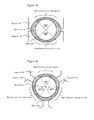
- wall thickness reduction will be performed on a region of a blank pipe defined by a central angle of 90° per each grooved roll disposed in each roll stand (see Figure 1A ).
- the region where wall thickness reduction is not performed by each grooved roll is the region of the blank pipe defined by a central angle of 45° respectively corresponding to a region closer to opposite flanges of each grooved roll, and the range where wall thickness reduction is not performed is larger compared to the case of a typical 3-roll type mandrel mill.
- Patent Literature 1 proposes a 3-roll type mandrel mill (claims of Patent Literature 1 etc.) in which the pressing directions of the grooved rolls are shifted by 40° for each roll stand among three roll stands which precede the final roll stand, and each grooved roll disposed in the above described three roll stands is formed so as to come into contact with a region of the blank pipe defined by a central angle of 40° (wall thickness reduction of the concerned region is performed).
- the grooved roll disposed in the first and second roll stands is reported to be one which is used in a typical 3-roll type mandrel mill as shown in Figure 3 of Patent Literature 1 etc.
- each grooved roll disposed in the first and second roll stands is configured to have a groove profile formed therein such that the grooved roll comes into contact with a region of the blank pipe defined by a central angle of 60° (wall thickness reduction is performed on the concerned region) (the central angle defining a circular arc constituting the groove bottom profile is set at 60°).
- the mandrel mill described in Patent Literature 1 is configured such that the pressing directions of the grooved rolls are shifted by 40° for each roll stand among a third to a fifth roll stands, and each grooved roll disposed in the third to fifth roll stands has a groove profile formed therein such that the grooved roll comes into contact with a region of the blank pipe defined by a central angle of 40° (wall thickness reduction is performed on the concerned region) (the central angle defining the circular arc constituting the groove bottom profile is set at 40°).
- the region where wall thickness reduction is not performed by each grooved roll disposed in the third to fifth roll stands is a region of the blank pipe defined by a central angle of 40° respectively corresponding to the region closer to opposite flanges of each grooved roll, and the range where wall thickness reduction is not performed is larger compared with the case of a typical 3-roll type mandrel mill. Therefore, in the mandrel mill described in Patent Literature 1, the amount of outward bulge of the blank pipe material during drawing and rolling will become larger in the third to fifth roll stands compared to the case of a typical 3-roll type mandrel mill.
- the present invention has been made to solve such problems of prior art, and has its object to provide a mandrel mill including a plurality of roll stands in which three grooved rolls are disposed in each roll stand, and which can adequately suppress a phenomenon in which the mandrel bar becomes unable to be pulled out from a pipe after drawing and rolling, without resulting in increase in facility cost and deterioration of maintainability, and a method for manufacturing a seamless pipe by using the mandrel mill.
- the grooved roll disposed in the first and second roll stands is a grooved roll which is used in a typical 3-roll type mandrel mill (a grooved roll in which the groove profile is formed such that the grooved roll comes into contact with a region of the blank pipe defined by a central angle of 60°), the amount of outward bulge of the blank pipe material during drawing and rolling in the first and second roll stands is small, thereby resulting in a smaller circumference of the blank pipe.
- the blank pipe material is a high alloyed steel such as a stainless steel
- the high alloyed steel has a high thermal shrinkage ratio, the shrinkage of the circumference of the blank pipe will remarkably increase.
- the present inventors found that to adequately suppress the phenomenon in which the mandrel bar becomes unable to be pulled out from a pipe after drawing and rolling, it is essential to form the grooved roll such that the amount of outward bulge of the blank pipe material increases during drawing and rolling at least in the first and second roll stands.
- the present invention has been achieved based on the above findings of the present inventors. That is, the present invention provides a mandrel mill comprising a plurality of roll stands in which three grooved rolls are disposed in each roll stand such that an angle formed by pressing directions is 120° and the pressing directions of grooved rolls are alternately shifted by 60° between adjacent roll stands, wherein a central angle defining a circular arc that constitutes a groove bottom profile in a groove profile of the grooved rolls disposed at least in the first and second roll stands is set at less than 60°, and a distance between a point on the groove profile excepting the groove bottom profile and a center of the circular arc is longer than a radius of the circular arc.
- the central angle defining a circular arc constituting a groove bottom profile (a profile of the vicinity of the groove bottom in a groove profile) of the grooved rolls disposed at least in the first and second roll stands is set at less than 60°. Further, the distance between a point on the groove profile excepting the groove bottom profile and the center of the circular arc is longer than the radius of the circular arc.
- the amount of outward bulge of the blank pipe or tube material during drawing and rolling at least in the first and second stand rolls is large, and even if the blank pipe or tube material is a high alloyed steel such as a stainless steel, it is possible to increase the circumference of the pipe after drawing and rolling. Therefore, it is possible to adequately suppress the phenomenon in which the mandrel bar becomes unable to be pulled out from a pipe or tube after drawing and rolling. Further, since in the mandrel mill relating to the present invention, the pressing directions of the grooved rolls are alternately shifted by 60° in all the roll stands as with a typical 3-roll type mandrel mill, the arrangement of the rotary drive shaft etc.
- the number of roll stands may be the same as that of a typical 3-roll type mandrel mill. Therefore, increase in facility cost and deterioration of maintainability will not result.
- the mandrel mill relating to the present invention it is possible to adequately suppress the phenomenon in which the mandrel bar becomes unable to be pulled out from a pipe or tube after drawing and rolling, without resulting in increase in facility cost and deterioration of maintainability.
- the central angle defining the circular arc constituting the groove bottom profile of the grooved rolls disposed at least in the first and second roll stands is set at not less than 30°. If the central angle is set at less than 30°, the region where wall thickness reduction is not performed in one roll stand will exceed 3/4 of the entire circumference of the blank pipe or tube, and even with the first and second roll stands combined, the region where wall thickness reduction is not performed will exceed 1/2 of the entire circumference of the blank pipe or tube. For this reason, the amount of reduction in wall thickness in the roll stands after the third roll stand becomes larger than that in the first and second roll stands resulting in a risk that the number of the roll stands after the third roll stand has to be increased.
- first roll stand in the present invention refers to a roll stand which is disposed at a first position counted from the entrance side of the mandrel mill.
- second roll stand in the present invention refers to a roll stand which is disposed at a second position counted from the entrance side of the mandrel mill.
- the wall thickness of a region of the blank pipe or tube (hereafter appropriately referred to as "intermediate portion" since it is a region which is rolled at an intermediate region between the groove bottom and the flange of the grooved roll) which is rolled by the region of each grooved roll located from the groove bottom to an angle of near 30° around the groove center tends to be larger than the wall thickness of other regions.
- the wall thickness reduction may be mainly performed on the above described intermediate portion from the viewpoint of preventing wall thickness eccentricity.
- the distance between a point on the groove profile of the grooved roll and the groove center is approximately constant over a range from the groove bottom to a region located at an angle of near 30° around the groove center. For this reason, in a wide range in a circumferential direction of the blank pipe or tube including not only the above described intermediate portion but also a region opposed to the groove bottom of the grooved roll, wall thickness reduction is performed on the blank pipe or tube between the grooved roll and the mandrel bar.
- the major bulging direction of the blank pipe or tube material during drawing and rolling in the final roll stand will be the longitudinal direction of the blank pipe or tube, and the amount of bulge in the circumferential direction of the blank pipe or tube is small so that the circumference of a pipe or tube after drawing and rolling becomes small.
- the phenomenon in which the mandrel bar becomes unable to be pulled out from a pipe or tube after drawing and rolling cannot adequately be suppressed.
- the inventors have conducted a diligent study in view of that forming a profile of the grooved roll such that the blank pipe or tube material mainly bulges in the circumferential direction of the blank pipe or tube during drawing and rolling in the final roll stand allows the circumference of the pipe or tube after drawing and rolling to be increased, thereby making it possible to further adequately suppress the phenomenon in which the mandrel bar becomes unable to be pulled out from a pipe or tube after drawing and rolling, and that wall thickness reduction may be mainly performed on the above described intermediate portion in the final roll stand, and eventually came to think of a preferred configuration of the mandrel mill relating to the present invention.
- a distance between a point of the groove profile of each grooved roll disposed in a final roll stand among roll stands for performing wall thickness reduction on a blank pipe or tube, and a groove center is not constant, and becomes a minimum at a point on the groove profile located at any angle in a range of not less than 27° and not more than 33° around the groove center from the groove bottom.
- the distance between a point on the groove profile and the groove center is not constant, but becomes a minimum at a point on the groove profile located at an angle of near 30° (not less than 27° and not more than 33°) around the groove center from the groove bottom, wall thickness reduction will be performed on the blank pipe or tube between the grooved roll and the mandrel bar only in the periphery of the intermediate portion described above.
- the final roll stand among the roll stands for performing wall thickness reduction on a blank pipe or tube refers to a roll stand which is disposed closest to the exit side of the mandrel mill among the roll stands for performing wall thickness reduction on a blank pipe or tube.
- the present invention also provides a mandrel mill including a plurality of roll stands in which three grooved rolls are disposed in each roll stand such that the angle formed by pressing directions is 120° and the pressing directions of grooved rolls are alternately shifted by 60° between adjacent roll stands, wherein a distance between a point of the groove profile of each grooved roll disposed in a final roll stand among roll stands for performing wall thickness reduction on a blank pipe or tube, and a groove center is not constant, and becomes a minimum at a point on the groove profile located at any angle in a range of not less than 27° and not more than 33° around the groove center from the groove bottom.
- the distance between a point on the groove profile and the groove center is not constant, but becomes a minimum at a point on the groove profile located at an angle of near 30° (not less than 27° and not more than 33°) around the groove center from the groove bottom, wall thickness reduction will be performed on the blank pipe or tube between the grooved roll and the mandrel bar only in the periphery of the intermediate portion described above.
- the pressing directions of the grooved rolls are alternately shifted by 60° in all the roll stands as with a typical 3-roll type mandrel mill, the arrangement of the rotary drive shaft etc. of the grooved roll will not become complicated unlike the mandrel mill described in Patent Literature 1. Furthermore, the number of roll stands may be the same as that of a typical 3-roll type mandrel mill. Therefore, increase in facility cost and deterioration of maintainability will not result.
- the mandrel mill relating to the present invention it is possible to adequately suppress the phenomenon in which the mandrel bar becomes unable to be pulled out from a pipe or tube after drawing and rolling, without resulting in increase in facility cost and deterioration of maintainability.
- the present invention further provides a method for manufacturing a seamless pipe or tube, comprising a step of drawing and rolling a blank pipe or tube by means of the above described mandrel mill.
- the mandrel mill relating to the present invention it is possible to adequately suppress the phenomenon in which the mandrel bar becomes unable to be pulled out from a pipe or tube after drawing and rolling, without resulting in increase in facility cost and deterioration of maintainability.
- a mandrel mill relating to the present embodiment includes a plurality of (five in the present embodiment) roll stands in which three grooved rolls are disposed in each roll stand such that an angle formed by the pressing directions is 120°, and the pressing directions of the grooved rolls are alternately shifted by 60° between adjacent roll stands.
- Figures 2A, 2B and 2C are longitudinal cross-sectional views schematically showing the configuration of a grooved roll disposed in a first and second roll stands of a mandrel mill relating to the present embodiment.
- Figure 2A shows a schematic configuration of three grooved rolls disposed in the first roll stand.
- Figure 2B shows a schematic configuration of three grooved rolls disposed in the second roll stand.
- Figure 2C shows a schematic configuration of each grooved roll disposed in the first and second roll stands.
- reference character O indicates a groove center (a pass line center of the blank pipe)
- reference character C1 indicates the center of a circular arc having a radius of R1.
- the distance (offset) between the groove center O and the center C1 of a circular arc is adjusted when blank pipes having different outer diameters and wall thicknesses are subjected to drawing and rolling with the same grooved roll, and is determined to be an appropriate value according to the outer diameter and wall thickness of the blank pipe to be subjected to drawing and rolling.
- the mandrel mill relating to the present embodiment is configured such that the central angle ⁇ defining a circular arc (radius R1) constituting a groove bottom profile of a grooved roll R disposed at least in the first and second roll stands is set at less than 60°, and the distance between a point on the groove profile P excepting the groove bottom profile and the center C1 of the circular arc is longer than the radius R1 of the circular arc.
- the amount of outward bulge of a blank pipe material during drawing and rolling is larger at least in the first and second roll stands compared to a conventional typical 3-roll type mandrel mill, and it is possible to increase the circumference of the pipe after drawing and rolling even if the blank pipe material is a high alloyed steel such as a stainless steel.
- the central angle ⁇ defining the circular arc constituting the groove bottom profile of each grooved roll R disposed at least in the first and second roll stands is preferably set at not less than 30°.
- the region where wall thickness reduction is not performed in one roll stand will exceed 3/4 of the entire circumference of the blank pipe, and even with the first and second roll stands combined, the region where wall thickness reduction is not performed will exceed 1/2 of the entire circumference of the blank pipe. For this reason, the amount of reduction in wall thickness in the roll stands after the third roll stand becomes larger than that in the first and second roll stands resulting in a risk that the number of the roll stands after the third roll stand has to be increased.
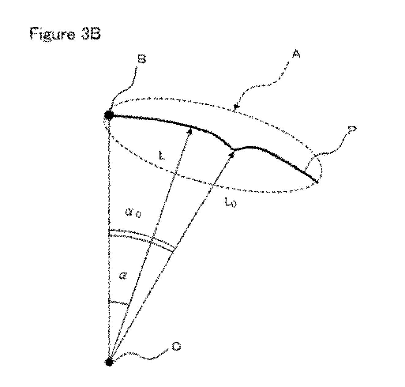
- Figures 3A, 3B and 3C are longitudinal cross-sectional views schematically showing a preferable configuration of a grooved roll disposed in a final roll stand (a fifth roll stand in the present embodiment) among the roll stands for performing wall thickness reduction on a blank pipe in the mandrel mill relating to the present embodiment.
- Figure 3A shows a schematic configuration of each grooved roll disposed in the fifth roll stand.
- Figure 3B shows in exaggeration a portion indicated by an arrow symbol A of the groove profile shown in Figure 3A.
- Figure 3C schematically shows the distance between the groove profile and the groove center of each grooved roll disposed in the fifth roll stand.
- reference character L indicates the distance between a point on the groove profile P, which is located at an angle ⁇ around the groove center O from the groove bottom B, and the groove center O.
- Figures 4A, 4B and 4C are explanatory diagrams for illustrating the effect of a grooved roll disposed in the final roll stand shown in Figures 3A, 3B and 3C .
- Figure 4A is a cross-sectional view schematically showing a situation where a blank pipe S is subjected to drawing and rolling by a grooved roll R and a mandrel bar M.
- Figure 4B is a view schematically showing a wall thickness reduction region A in a conventional final roll stand. The figure on the upper side of Figure 4B shows a view seen from the pressing direction of the grooved roll R, and the figure on the lower side shows a view seen from the roll direction.
- Figure 4C is a view schematically showing a wall thickness reduction region A in a final roll stand in which the grooved roll shown in Figures 3A, 3B and 3C is disposed.
- the figure on the upper side of Figure 4C shows a view seen from the pressing direction of the grooved roll R, and the figure on the lower side shows a view seen from the roll direction.
- reference character X indicates the circumferential direction of the blank pipe S
- reference character Y indicates the pressing direction by the grooved roll R
- reference character Z indicates the roll direction.
- hollow arrow symbols indicate the flow of the blank pipe material
- solid black arrow symbols indicate wall thickness reduction locations.
- a blank pipe S in Figures 4B and 4C indicates the blank pipe at the entrance side of the final roll stand.
- the distance between a point on the groove profile P of the grooved roll R and the groove center O is approximately constant over a range from the groove bottom B to a region located at an angle of near 30° around the groove center O.
- the major bulging direction of the blank pipe material during drawing and rolling in the final roll stand will be the longitudinal direction (Z direction) of the blank pipe S, and the amount of bulging in the circumferential direction (X direction) of the blank pipe S is small so that the circumference of the pipe after drawing and rolling will have become small.
- Z direction the longitudinal direction
- X direction the circumferential direction
- the distance L between a point on the groove profile P and the groove center O is not constant, and becomes a minimum value L 0 at a point on the groove profile P located at an angle ⁇ 0 of near 30° (not less than 27° and not more than 33°) around the groove center O from the groove bottom B.
- wall thickness reduction will be performed on the blank pipe S between the grooved roll R and the mandrel bar M only in the periphery A of the intermediate portion described above.
- the major direction in which the blank pipe material bulges during drawing and rolling in the final roll stand will be the circumferential direction (X direction) of the blank pipe S, the circumference of the pipe after drawing and rolling becomes larger compared to a case where drawing and rolling is performed in a conventional final roll stand ( Figure 4B ).
- X direction the circumferential direction of the blank pipe S
- Figure 4B the circumference of the pipe after drawing and rolling becomes larger compared to a case where drawing and rolling is performed in a conventional final roll stand
- a mandrel mill relating to the present embodiment includes, as with the first embodiment, a plurality of (five in the present embodiment) roll stands in which three grooved rolls are disposed in each roll stand such that an angle formed by the pressing directions is 120°, and the pressing directions of the grooved rolls are alternately shifted by 60° between adjacent roll stands.
- the central angle ⁇ defining a circular arc (radius R1) constituting the groove bottom profile of the grooved roll R disposed at least in the first and second roll stands be set at less than 60°.
- the distance L between a point on the groove profile P and the groove center O is not constant, and becomes a minimum value L 0 at a point on the groove profile P located at an angle ⁇ 0 of near 30° (not less than 27° and not more than 33°) around the groove center O from the groove bottom B.
- wall thickness reduction will be performed on the blank pipe S between the grooved roll R and the mandrel bar M only in the periphery A of the intermediate portion described above (a region of the blank pipe S which is rolled at a region of grooved roll R located from the groove bottom B to an angle of near 30° around the groove center O).
- FEM finite element method
- FEM finite element method
- FEM finite element method
- FEM finite element method
- Figure 5 shows evaluation results of Examples 1-1 to 1-3, and Comparative Example 1.
- an angle range shown by an arrow line shows a range where the pipe and the mandrel bar are in contact with each other.
- the result indicated that the ratio of contact between the pipe and the mandrel bar was reduced and the inner circumference of the pipe increased for any of Examples 1-1 to 1-3 compared to Comparative Example 1.
- Example 1-3 resulted in showing the largest inner circumference of the pipe. From these results, it is expected that according to the mandrel mill relating to the present invention, it is possible to adequately suppress the phenomenon in which the mandrel bar becomes unable to be pulled out from a pipe after drawing and rolling.
- FEM finite element method
- the cross-sectional shape of a pipe at the exit side of a mandrel mill was evaluated by carrying out analysis using a finite element method (FEM) at the same conditions as those of Example 2-1 excepting that the distance L between a point on the groove profile P and the groove center O of the grooved roll R disposed in the fifth roll stand is not constant, and becomes a minimum at a point on the groove profile P located at an angle of 30° around the groove center O from the groove bottom B.
- FEM finite element method
- FEM finite element method
- Figure 6 shows evaluation results of Examples 2-1 and 2-2, and Comparative Example 2.
- an angle range shown by an arrow line shows a range where the pipe and the mandrel bar are in contact with each other.
- the results indicated that the ratio of contact between the pipe and the mandrel bar decreased and the inner circumference of the pipe increased for any of Examples 2-1 and 2-2 compared to Comparative Example 2.
- Example 2-2 resulted in showing the largest inner circumference of the pipe. From these results, it is expected that according to the mandrel mill relating to the present invention, it is possible to adequately suppress the phenomenon in which the mandrel bar becomes unable to be pulled out from a pipe after drawing and rolling.
- FEM finite element method
- the cross-sectional shape of a pipe at the exit side of the mandrel mill was evaluated by carrying out analysis using a finite element method (FEM) at the same conditions as those of Example 3 excepting that the distance L between a point on the groove profile P and the groove center O of the grooved roll R disposed in the fifth roll stand is approximately constant over a range from the grove bottom B to a point on the groove profile P located at an angle of 30° around the groove center O from the groove bottom B.
- FEM finite element method
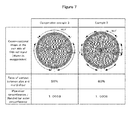
- Figure 7 shows evaluation results of Examples 3 and Comparative Example 3.
- an angle range shown by an arrow line shows a range where the pipe and the mandrel bar are in contact with each other.
- the results indicated that the ratio of contact between the pipe and the mandrel bar decreased, and the inner circumference of the pipe increased for Example 3 compared to Comparative Example 3. From these results, it is expected that according to the mandrel mill relating to the present invention, it is possible to adequately suppress the phenomenon in which the mandrel bar becomes unable to be pulled out from a pipe after drawing and rolling.
- FEM finite element method
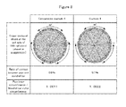
- Figure 8 shows evaluation results of Example 4 and Comparative Example 4.
- an angle range shown by an arrow line shows a range where the pipe and the mandrel bar are in contact with each other.
- the results indicated that the ratio of contact between the pipe and the mandrel bar decreased, and the inner circumference of the pipe increased for Example 4 compared to Comparative Example 4. From these results, it is expected that according to the mandrel mill relating to the present invention, it is possible to adequately suppress the phenomenon in which the mandrel bar becomes unable to be pulled out from a pipe after drawing and rolling.
Landscapes
- Engineering & Computer Science (AREA)
- Mechanical Engineering (AREA)
- Physics & Mathematics (AREA)
- Geometry (AREA)
- Reduction Rolling/Reduction Stand/Operation Of Reduction Machine (AREA)
Abstract

Description
- The present invention relates to a mandrel mill including a plurality of roll stands, in each of which three grooved rolls are disposed, and a method for manufacturing a seamless pipe or tube by using the mandrel mill. In particular, the present invention relates to a mandrel mill which is capable of adequately suppressing a phenomenon in which when a blank pipe or tube is subjected to drawing and rolling, a circumference of the blank pipe is excessively reduced and thereby an inner surface of the blank pipe squeezes a mandrel bar, thus making the mandrel bar unable to be pulled out from a pipe after drawing and rolling, and a method for manufacturing a seamless pipe by using the mandrel mill. Hereinafter, "pipe or tube" is referred to as "pipe" when deemed appropriate.
- In the manufacturing of a seamless pipe by the Mannesmann-mandrel mill process, first, a round billet or square billet is heated in a heating furnace and thereafter pierced and rolled by a piercing mill to manufacture a hollow blank pipe. Next, a mandrel bar is inserted into the inner face of the hollow blank pipe to be subjected to drawing and rolling by a mandrel mill including a plurality of roll stands. Thereafter, the pipe after drawing and rolling is rolled into a predetermined outer diameter by means of a reducing mill, thus providing a product.
- As the mandrel mill described above, conventionally, widely used is a 2-roll type mandrel mill including a plurality of roll stands, in which two opposing grooved rolls are disposed in each roll stand, and the pressing directions of the grooved rolls are alternately shifted by 90° between adjacent roll stands.
In this 2-roll type mandrel mill, there is a risk that scoring may occur between a grooved roll and a blank pipe in the vicinity of a flange of the grooved roll caused by an excessive difference in circumferential speed between the groove bottom and the flange of the grooved roll, and a flaw (fin flaw) may occur in the blank pipe caused by excessive finning of the blank pipe material at a flange of the grooved roll. In view of preventing such scoring and fin flaws, in the 2-roll type mandrel mill, the grooved roll is generally designed such that the radius of curvature is larger at both ends of the groove profile (the groove shape obtained by sectioning the grooved roll with a plane that passes through the rotation center of the grooved roll). In this case, since the region of the blank pipe corresponding to the vicinity of the flange of the grooved roll is only subject to a tension in the longitudinal direction without being restricted either by the grooved roll or the mandrel bar, it is difficult to control the deformation (bulging) in the pipe circumferential direction. For this reason, a problem exists in that a pinhole defect etc. is likely to occur in a pipe made of a material having a low hot deformability such as a stainless steel. - To solve the above described problems of a 2-roll type mandrel mill, recently, a 3-roll type mandrel mill has become introduced in which three grooved rolls are disposed in each roll stand.
A typical 3-roll type mandrel mill includes a plurality of roll stands, in which three grooved rolls are disposed in each roll stand such that the angle formed by pressing directions is 120°, and the pressing directions of the grooved rolls are alternately shifted by 60° between adjacent roll stands. - In a typical 3-roll type mandrel mill, as described above, the pressing directions of the grooved rolls are alternately shifted by 60° between adjacent roll stands. Therefore, when wall thickness reduction is performed on the entire circumference of a blank pipe by a pair of adjacent roll stands, it is necessary to perform wall thickness reduction on a region of the blank pipe defined by a central angle of 60° per each grooved roll disposed in each roll stand (see
Figure 1B ). In other words, the region where wall thickness reduction is not performed by each grooved roll is only the regions of the blank pipe defined by a central angle of 30° respectively corresponding to a region closer to opposite flanges of each grooved roll. Moreover, to perform wall thickness reduction on a region of the blank pipe defined by a central angle of 60°, the central angle defining a circular arc constituting a groove bottom profile (the profile in the vicinity of the grove bottom of a groove profile) of each grooved roll is set at 60° or more.
In contrast, in a 2-roll type mandrel mill, wall thickness reduction will be performed on a region of a blank pipe defined by a central angle of 90° per each grooved roll disposed in each roll stand (seeFigure 1A ). In other words, the region where wall thickness reduction is not performed by each grooved roll is the region of the blank pipe defined by a central angle of 45° respectively corresponding to a region closer to opposite flanges of each grooved roll, and the range where wall thickness reduction is not performed is larger compared to the case of a typical 3-roll type mandrel mill.
Therefore, in the case of a typical 3-roll type mandrel mill, since the amount of outward bulge of the blank pipe material during drawing and rolling is smaller compared to the case of a 2-roll type mandrel mill, there is a risk that the circumference of the blank pipe is reduced due to drawing and rolling, and thereby the inner surface of the blank pipe squeezes the mandrel bar so that the mandrel bar becomes unable to be pulled out from a pipe after drawing and rolling. - To solve the problems of a typical 3-roll type mandrel mill as described above,
Patent Literature 1 proposes a 3-roll type mandrel mill (claims ofPatent Literature 1 etc.) in which the pressing directions of the grooved rolls are shifted by 40° for each roll stand among three roll stands which precede the final roll stand, and each grooved roll disposed in the above described three roll stands is formed so as to come into contact with a region of the blank pipe defined by a central angle of 40° (wall thickness reduction of the concerned region is performed).
To be specific, in the mandrel mill described inPatent Literature 1, the grooved roll disposed in the first and second roll stands is reported to be one which is used in a typical 3-roll type mandrel mill as shown inFigure 3 ofPatent Literature 1 etc. That is, the pressing directions of the grooved rolls are shifted by 60° between the first and second roll stands, and each grooved roll disposed in the first and second roll stands is configured to have a groove profile formed therein such that the grooved roll comes into contact with a region of the blank pipe defined by a central angle of 60° (wall thickness reduction is performed on the concerned region) (the central angle defining a circular arc constituting the groove bottom profile is set at 60°).
Further, the mandrel mill described inPatent Literature 1 is configured such that the pressing directions of the grooved rolls are shifted by 40° for each roll stand among a third to a fifth roll stands, and each grooved roll disposed in the third to fifth roll stands has a groove profile formed therein such that the grooved roll comes into contact with a region of the blank pipe defined by a central angle of 40° (wall thickness reduction is performed on the concerned region) (the central angle defining the circular arc constituting the groove bottom profile is set at 40°).
In other words, in the mandrel mill described inPatent Literature 1, the region where wall thickness reduction is not performed by each grooved roll disposed in the third to fifth roll stands is a region of the blank pipe defined by a central angle of 40° respectively corresponding to the region closer to opposite flanges of each grooved roll, and the range where wall thickness reduction is not performed is larger compared with the case of a typical 3-roll type mandrel mill. Therefore, in the mandrel mill described inPatent Literature 1, the amount of outward bulge of the blank pipe material during drawing and rolling will become larger in the third to fifth roll stands compared to the case of a typical 3-roll type mandrel mill. - [Patent Literature 1]
JP7-47410A - However, from the investigation conducted by the present inventors, it is found that in the mandrel mill described in
Patent Literature 1, particularly when the blank pipe material is a high alloyed steel such as a stainless steel, the phenomenon in which the mandrel bar becomes unable to be pulled out from a pipe after drawing and rolling cannot be adequately suppressed.
Moreover, in the mandrel mill described inPatent Literature 1, while the pressing directions of grooved rolls are shifted by 60° between the first and second roll stands, the pressing directions of the grooved rolls are shifted by 40° for each roll stand among the third to fifth roll stands. As a result of this, in the mandrel mill described inPatent Literature 1, in contrast to a typical 3-roll type mandrel mill in which the pressing directions of grooved rolls are alternately shifted by 60° in a range from the first roll stand to the final roll stand, the arrangement of the rotary drive shaft etc. of the grooved roll will become complicated thereby resulting in increase in facility cost and deterioration of maintainability.
Further, while in a typical 3-roll type mandrel mill, wall thickness reduction is performed on the entire circumference of the blank pipe in adjacent two roll stands, the wall thickness reduction is performed on the entire circumference of the blank pipe in three roll stands (a third to a fifth roll stands) in the mandrel mill described inPatent Literature 1. For this reason, in the mandrel mill described inPatent Literature 1, the number of roll stands increases compared to a typical 3-roll type mandrel mill, thereby resulting in increase in facility cost and deterioration of maintainability. - The present invention has been made to solve such problems of prior art, and has its object to provide a mandrel mill including a plurality of roll stands in which three grooved rolls are disposed in each roll stand, and which can adequately suppress a phenomenon in which the mandrel bar becomes unable to be pulled out from a pipe after drawing and rolling, without resulting in increase in facility cost and deterioration of maintainability, and a method for manufacturing a seamless pipe by using the mandrel mill.
- In order to solve the above described problems, the present inventors have conducted a diligent study eventually obtaining the following findings.
Since, in the mandrel mill described inPatent Literature 1, the grooved roll disposed in the first and second roll stands is a grooved roll which is used in a typical 3-roll type mandrel mill (a grooved roll in which the groove profile is formed such that the grooved roll comes into contact with a region of the blank pipe defined by a central angle of 60°), the amount of outward bulge of the blank pipe material during drawing and rolling in the first and second roll stands is small, thereby resulting in a smaller circumference of the blank pipe. In particular, when the blank pipe material is a high alloyed steel such as a stainless steel, since in addition to that the amount of outward bulge of the blank pipe material will be further reduced, the high alloyed steel has a high thermal shrinkage ratio, the shrinkage of the circumference of the blank pipe will remarkably increase. Accordingly, it is found that once the circumference of the blank pipe has become excessively small due to the drawing and rolling in the first and second roll stands, even if the blank pipe is subjected to drawing and rolling by a grooved roll which is formed such that the amount of outward bulge of the blank pipe material increases during drawing and rolling in the third to fifth roll stands (a grooved roll in which groove profile is formed such that the grooved roll comes into contact with a region of the blank pipe defined by a central angle of 40°), the circumference of the pipe after the drawing and rolling will not increase, and the phenomenon in which the mandrel bar becomes unable to be pulled out from a pipe after drawing and rolling cannot be adequately suppressed. In other words, the present inventors found that to adequately suppress the phenomenon in which the mandrel bar becomes unable to be pulled out from a pipe after drawing and rolling, it is essential to form the grooved roll such that the amount of outward bulge of the blank pipe material increases during drawing and rolling at least in the first and second roll stands. - The present invention has been achieved based on the above findings of the present inventors. That is, the present invention provides a mandrel mill comprising a plurality of roll stands in which three grooved rolls are disposed in each roll stand such that an angle formed by pressing directions is 120° and the pressing directions of grooved rolls are alternately shifted by 60° between adjacent roll stands, wherein a central angle defining a circular arc that constitutes a groove bottom profile in a groove profile of the grooved rolls disposed at least in the first and second roll stands is set at less than 60°, and a distance between a point on the groove profile excepting the groove bottom profile and a center of the circular arc is longer than a radius of the circular arc.
- In the mandrel mill relating to the present invention, the central angle defining a circular arc constituting a groove bottom profile (a profile of the vicinity of the groove bottom in a groove profile) of the grooved rolls disposed at least in the first and second roll stands is set at less than 60°. Further, the distance between a point on the groove profile excepting the groove bottom profile and the center of the circular arc is longer than the radius of the circular arc. Therefore, compared to a conventional typical 3-roll type mandrel mill, the amount of outward bulge of the blank pipe or tube material during drawing and rolling at least in the first and second stand rolls is large, and even if the blank pipe or tube material is a high alloyed steel such as a stainless steel, it is possible to increase the circumference of the pipe after drawing and rolling. Therefore, it is possible to adequately suppress the phenomenon in which the mandrel bar becomes unable to be pulled out from a pipe or tube after drawing and rolling.
Further, since in the mandrel mill relating to the present invention, the pressing directions of the grooved rolls are alternately shifted by 60° in all the roll stands as with a typical 3-roll type mandrel mill, the arrangement of the rotary drive shaft etc. of the grooved roll will not become complicated unlike the mandrel mill described inPatent Literature 1. Furthermore, the number of roll stands may be the same as that of a typical 3-roll type mandrel mill. Therefore, increase in facility cost and deterioration of maintainability will not result.
As so far described, according to the mandrel mill relating to the present invention, it is possible to adequately suppress the phenomenon in which the mandrel bar becomes unable to be pulled out from a pipe or tube after drawing and rolling, without resulting in increase in facility cost and deterioration of maintainability.
Moreover, configuring not only the grooved rolls disposed in the first and second roll stands, but also the grooved rolls disposed in the roll stands after the third roll stand such that the central angle defining a circular arc constituting the groove bottom profile is set at less than 60°, and the distance between a point on the groove profile excepting the groove bottom profile and the center of the circular arc is larger than the radius of the circular arc, will make it possible to more adequately suppress the phenomenon in which the mandrel bar becomes unable to be pulled out from a pipe or tube after drawing and rolling. - Here, it is preferable that the central angle defining the circular arc constituting the groove bottom profile of the grooved rolls disposed at least in the first and second roll stands is set at not less than 30°. If the central angle is set at less than 30°, the region where wall thickness reduction is not performed in one roll stand will exceed 3/4 of the entire circumference of the blank pipe or tube, and even with the first and second roll stands combined, the region where wall thickness reduction is not performed will exceed 1/2 of the entire circumference of the blank pipe or tube. For this reason, the amount of reduction in wall thickness in the roll stands after the third roll stand becomes larger than that in the first and second roll stands resulting in a risk that the number of the roll stands after the third roll stand has to be increased.
- Further, the "first roll stand" in the present invention refers to a roll stand which is disposed at a first position counted from the entrance side of the mandrel mill. Similarly, the "second roll stand" in the present invention refers to a roll stand which is disposed at a second position counted from the entrance side of the mandrel mill.
- Here, it is known that when three grooved rolls are disposed in each roll stand such that the angle formed by pressing directions is 120°, and the pressing directions of the grooved rolls are alternately shifted by 60° between adjacent roll stands, the wall thickness of a region of the blank pipe or tube (hereafter appropriately referred to as "intermediate portion" since it is a region which is rolled at an intermediate region between the groove bottom and the flange of the grooved roll) which is rolled by the region of each grooved roll located from the groove bottom to an angle of near 30° around the groove center tends to be larger than the wall thickness of other regions.
Therefore, in the final roll stand among the roll stands for performing wall thickness reduction on a blank pipe or tube, the wall thickness reduction may be mainly performed on the above described intermediate portion from the viewpoint of preventing wall thickness eccentricity.
However, in the final roll stand of a conventional typical 3-roll type mandrel mill, it is general that the distance between a point on the groove profile of the grooved roll and the groove center is approximately constant over a range from the groove bottom to a region located at an angle of near 30° around the groove center. For this reason, in a wide range in a circumferential direction of the blank pipe or tube including not only the above described intermediate portion but also a region opposed to the groove bottom of the grooved roll, wall thickness reduction is performed on the blank pipe or tube between the grooved roll and the mandrel bar. Therefore, the major bulging direction of the blank pipe or tube material during drawing and rolling in the final roll stand will be the longitudinal direction of the blank pipe or tube, and the amount of bulge in the circumferential direction of the blank pipe or tube is small so that the circumference of a pipe or tube after drawing and rolling becomes small. As a result of this, there is a risk that the phenomenon in which the mandrel bar becomes unable to be pulled out from a pipe or tube after drawing and rolling cannot adequately be suppressed. - The inventors have conducted a diligent study in view of that forming a profile of the grooved roll such that the blank pipe or tube material mainly bulges in the circumferential direction of the blank pipe or tube during drawing and rolling in the final roll stand allows the circumference of the pipe or tube after drawing and rolling to be increased, thereby making it possible to further adequately suppress the phenomenon in which the mandrel bar becomes unable to be pulled out from a pipe or tube after drawing and rolling, and that wall thickness reduction may be mainly performed on the above described intermediate portion in the final roll stand, and eventually came to think of a preferred configuration of the mandrel mill relating to the present invention.
That is, preferably, a distance between a point of the groove profile of each grooved roll disposed in a final roll stand among roll stands for performing wall thickness reduction on a blank pipe or tube, and a groove center is not constant, and becomes a minimum at a point on the groove profile located at any angle in a range of not less than 27° and not more than 33° around the groove center from the groove bottom. - According to such a preferable configuration, since in the final roll stand, the distance between a point on the groove profile and the groove center is not constant, but becomes a minimum at a point on the groove profile located at an angle of near 30° (not less than 27° and not more than 33°) around the groove center from the groove bottom, wall thickness reduction will be performed on the blank pipe or tube between the grooved roll and the mandrel bar only in the periphery of the intermediate portion described above. For this reason, since the major direction in which the blank pipe or tube material bulges during drawing and rolling in the final roll stand will be the circumferential direction of the blank pipe or tube, the circumference of the pipe or tube after drawing and rolling increases compared with the case where drawing and rolling is performed in a final roll stand in which a grooved roll having a groove profile as in prior art is disposed. As a result of this, it is made possible to further adequately suppress the phenomenon in which the mandrel bar becomes unable to be pulled out from a pipe or tube after drawing and rolling.
- It is noted that "the final roll stand among the roll stands for performing wall thickness reduction on a blank pipe or tube" in the present invention refers to a roll stand which is disposed closest to the exit side of the mandrel mill among the roll stands for performing wall thickness reduction on a blank pipe or tube.
- In order to solve the above described problems, the present invention also provides a mandrel mill including a plurality of roll stands in which three grooved rolls are disposed in each roll stand such that the angle formed by pressing directions is 120° and the pressing directions of grooved rolls are alternately shifted by 60° between adjacent roll stands, wherein a distance between a point of the groove profile of each grooved roll disposed in a final roll stand among roll stands for performing wall thickness reduction on a blank pipe or tube, and a groove center is not constant, and becomes a minimum at a point on the groove profile located at any angle in a range of not less than 27° and not more than 33° around the groove center from the groove bottom.
- According to the present invention, since in the final roll stand, the distance between a point on the groove profile and the groove center is not constant, but becomes a minimum at a point on the groove profile located at an angle of near 30° (not less than 27° and not more than 33°) around the groove center from the groove bottom, wall thickness reduction will be performed on the blank pipe or tube between the grooved roll and the mandrel bar only in the periphery of the intermediate portion described above. For this reason, since the major direction in which the blank pipe or tube material bulges during drawing and rolling in the final roll stand will be the circumferential direction of the blank pipe or tube, the circumference of the pipe or tube after drawing and rolling increases compared with the case where drawing and rolling is performed in a final roll stand in which a grooved roll having a groove profile as in prior art is disposed. As a result of this, it is made possible to further adequately suppress the phenomenon in which the mandrel bar becomes unable to be pulled out from a pipe or tube after drawing and rolling.
Further, since in the mandrel mill relating to the present invention, the pressing directions of the grooved rolls are alternately shifted by 60° in all the roll stands as with a typical 3-roll type mandrel mill, the arrangement of the rotary drive shaft etc. of the grooved roll will not become complicated unlike the mandrel mill described inPatent Literature 1. Furthermore, the number of roll stands may be the same as that of a typical 3-roll type mandrel mill. Therefore, increase in facility cost and deterioration of maintainability will not result.
As so far described, according to the mandrel mill relating to the present invention, it is possible to adequately suppress the phenomenon in which the mandrel bar becomes unable to be pulled out from a pipe or tube after drawing and rolling, without resulting in increase in facility cost and deterioration of maintainability. - In order to solve the above described problems, the present invention further provides a method for manufacturing a seamless pipe or tube, comprising a step of drawing and rolling a blank pipe or tube by means of the above described mandrel mill.
- According to the mandrel mill relating to the present invention, it is possible to adequately suppress the phenomenon in which the mandrel bar becomes unable to be pulled out from a pipe or tube after drawing and rolling, without resulting in increase in facility cost and deterioration of maintainability.
-
-
Figures 1A and 1B are longitudinal cross-sectional views illustrating the difference between a 2-roll type mandrel mill and a 3-roll type mandrel mill. -
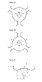
Figures 2A, 2B and 2C are longitudinal cross-sectional views schematically showing the configuration of a grooved roll disposed in a first and second roll stands of a mandrel mill relating to one embodiment of the present invention. -
Figures 3A, 3B and 3C are longitudinal cross-sectional views schematically showing a preferable configuration of a grooved roll disposed in a final roll stand among the roll stands for performing wall thickness reduction on a blank pipe in the mandrel mill relating to one embodiment of the present invention. -
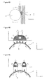
Figures 4A, 4B and 4C are explanatory diagrams for illustrating the effect of a grooved roll disposed in the final roll stand shown inFigures 3A, 3B and 3C . -
Figure 5 shows evaluation results of Examples 1-1 to 1-3, and Comparative Example 1. -
Figure 6 shows evaluation results of Examples 2-1 and 2-2, and Comparative Example 2. -
Figure 7 shows evaluation results of Examples 3 and Comparative Example 3. -
Figure 8 shows evaluation results of Example 4 and Comparative Example 4. - Hereafter, embodiments of the present invention will be described appropriately referring to the appended drawings.
- A mandrel mill relating to the present embodiment includes a plurality of (five in the present embodiment) roll stands in which three grooved rolls are disposed in each roll stand such that an angle formed by the pressing directions is 120°, and the pressing directions of the grooved rolls are alternately shifted by 60° between adjacent roll stands.
-
Figures 2A, 2B and 2C are longitudinal cross-sectional views schematically showing the configuration of a grooved roll disposed in a first and second roll stands of a mandrel mill relating to the present embodiment.Figure 2A shows a schematic configuration of three grooved rolls disposed in the first roll stand.Figure 2B shows a schematic configuration of three grooved rolls disposed in the second roll stand.Figure 2C shows a schematic configuration of each grooved roll disposed in the first and second roll stands. InFigures 2A, 2B and 2C , reference character O indicates a groove center (a pass line center of the blank pipe), and reference character C1 indicates the center of a circular arc having a radius of R1. The distance (offset) between the groove center O and the center C1 of a circular arc is adjusted when blank pipes having different outer diameters and wall thicknesses are subjected to drawing and rolling with the same grooved roll, and is determined to be an appropriate value according to the outer diameter and wall thickness of the blank pipe to be subjected to drawing and rolling.
As shown inFigures 2A, 2B and 2C , the mandrel mill relating to the present embodiment is configured such that the central angle θ defining a circular arc (radius R1) constituting a groove bottom profile of a grooved roll R disposed at least in the first and second roll stands is set at less than 60°, and the distance between a point on the groove profile P excepting the groove bottom profile and the center C1 of the circular arc is longer than the radius R1 of the circular arc. Owing to such a configuration, in the mandrel mill relating to the present embodiment, the amount of outward bulge of a blank pipe material during drawing and rolling is larger at least in the first and second roll stands compared to a conventional typical 3-roll type mandrel mill, and it is possible to increase the circumference of the pipe after drawing and rolling even if the blank pipe material is a high alloyed steel such as a stainless steel. Thus, it is possible to adequately suppress the phenomenon in which the mandrel bar becomes unable to be pulled out from a pipe after drawing and rolling.
It is to be noted that the central angle θ defining the circular arc constituting the groove bottom profile of each grooved roll R disposed at least in the first and second roll stands is preferably set at not less than 30°. If the central angle θ is set at less than 30°, the region where wall thickness reduction is not performed in one roll stand will exceed 3/4 of the entire circumference of the blank pipe, and even with the first and second roll stands combined, the region where wall thickness reduction is not performed will exceed 1/2 of the entire circumference of the blank pipe. For this reason, the amount of reduction in wall thickness in the roll stands after the third roll stand becomes larger than that in the first and second roll stands resulting in a risk that the number of the roll stands after the third roll stand has to be increased. -
Figures 3A, 3B and 3C are longitudinal cross-sectional views schematically showing a preferable configuration of a grooved roll disposed in a final roll stand (a fifth roll stand in the present embodiment) among the roll stands for performing wall thickness reduction on a blank pipe in the mandrel mill relating to the present embodiment.Figure 3A shows a schematic configuration of each grooved roll disposed in the fifth roll stand.Figure 3B shows in exaggeration a portion indicated by an arrow symbol A of the groove profile shown inFigure 3A. Figure 3C schematically shows the distance between the groove profile and the groove center of each grooved roll disposed in the fifth roll stand. InFigures 3A, 3B and 3C , reference character L indicates the distance between a point on the groove profile P, which is located at an angle α around the groove center O from the groove bottom B, and the groove center O.
As shown inFigures 3A, 3B and 3C , in a preferable configuration of the mandrel mill relating to the present embodiment, the distance L between a point on the groove profile P and the groove center O of the grooved roll R disposed in the final roll stand (the fifth roll stand) is not constant, and becomes a minimum value L0 at a point on the groove profile P located at an angle α0(27° ≤ α0 ≤ 33°) around the groove center O from the groove bottom B. That is, at α = α0, the distance L between a point on the groove profile P and the groove center O is given as L = L0. -
Figures 4A, 4B and 4C are explanatory diagrams for illustrating the effect of a grooved roll disposed in the final roll stand shown inFigures 3A, 3B and 3C .Figure 4A is a cross-sectional view schematically showing a situation where a blank pipe S is subjected to drawing and rolling by a grooved roll R and a mandrel bar M.Figure 4B is a view schematically showing a wall thickness reduction region A in a conventional final roll stand. The figure on the upper side ofFigure 4B shows a view seen from the pressing direction of the grooved roll R, and the figure on the lower side shows a view seen from the roll direction.Figure 4C is a view schematically showing a wall thickness reduction region A in a final roll stand in which the grooved roll shown inFigures 3A, 3B and 3C is disposed. The figure on the upper side ofFigure 4C shows a view seen from the pressing direction of the grooved roll R, and the figure on the lower side shows a view seen from the roll direction. InFigures 4A, 4B and 4C , reference character X indicates the circumferential direction of the blank pipe S, reference character Y indicates the pressing direction by the grooved roll R, and reference character Z indicates the roll direction. Moreover, inFigures 4A, 4B and 4C , hollow arrow symbols indicate the flow of the blank pipe material, and solid black arrow symbols indicate wall thickness reduction locations. Further, a blank pipe S inFigures 4B and 4C indicates the blank pipe at the entrance side of the final roll stand.
In a conventional final roll stand, it is general that the distance between a point on the groove profile P of the grooved roll R and the groove center O is approximately constant over a range from the groove bottom B to a region located at an angle of near 30° around the groove center O. For this reason, as shown inFigure 4B , in a wide range A in the circumferential direction of the blank pipe S including not only an intermediate portion (a region of the blank pipe S which is rolled at a region of each grooved roll R located from the groove bottom B to an angle of near 30° around the groove center O), but also a region opposed to the groove bottom B of the grooved roll R, wall thickness reduction will be performed on the blank pipe S between the grooved roll R and the mandrel bar M. Thus, the major bulging direction of the blank pipe material during drawing and rolling in the final roll stand will be the longitudinal direction (Z direction) of the blank pipe S, and the amount of bulging in the circumferential direction (X direction) of the blank pipe S is small so that the circumference of the pipe after drawing and rolling will have become small. As a result of this, there is a risk that it is not possible to adequately suppress the phenomenon in which the mandrel bar M becomes unable to be pulled out from a pipe after drawing and rolling.
On the other hand, in the final roll stand in which the grooved roll R shown inFigures 3A, 3B and 3C is disposed, the distance L between a point on the groove profile P and the groove center O is not constant, and becomes a minimum value L0 at a point on the groove profile P located at an angle α0of near 30° (not less than 27° and not more than 33°) around the groove center O from the groove bottom B. As a result of this, as shown inFigure 4C , wall thickness reduction will be performed on the blank pipe S between the grooved roll R and the mandrel bar M only in the periphery A of the intermediate portion described above. For this reason, the major direction in which the blank pipe material bulges during drawing and rolling in the final roll stand will be the circumferential direction (X direction) of the blank pipe S, the circumference of the pipe after drawing and rolling becomes larger compared to a case where drawing and rolling is performed in a conventional final roll stand (Figure 4B ). As a result of this, it is possible to further adequately suppress the phenomenon in which the mandrel bar M becomes unable to be pulled out from a pipe after drawing and rolling. - A mandrel mill relating to the present embodiment includes, as with the first embodiment, a plurality of (five in the present embodiment) roll stands in which three grooved rolls are disposed in each roll stand such that an angle formed by the pressing directions is 120°, and the pressing directions of the grooved rolls are alternately shifted by 60° between adjacent roll stands.
Moreover, as with a preferable configuration of the mandrel mill relating to the first embodiment as described with reference toFigures 3A, 3B and 3C , in the mandrel mill relating to the present embodiment as well, the distance L between a point on the groove profile P and the groove center O of the grooved roll R disposed in the final roll stand (the fifth roll stand) is not constant, and becomes a minimum value L0 at a point on the groove profile P located at an angle α0(27° ≤ α0 ≤ 33°) around the groove center O from the groove bottom B. That is, at α = α0, the distance L between the groove profile P and the groove center O is given as L = L0.
However, as to the mandrel mill relating to the present embodiment, in contrast to the mandrel mill relating to the first embodiment, there is no restriction that the central angle θ defining a circular arc (radius R1) constituting the groove bottom profile of the grooved roll R disposed at least in the first and second roll stands be set at less than 60°. - As described above, in the final roll stand of the mandrel mill relating to the present embodiment, the distance L between a point on the groove profile P and the groove center O is not constant, and becomes a minimum value L0 at a point on the groove profile P located at an angle α0of near 30° (not less than 27° and not more than 33°) around the groove center O from the groove bottom B. For this reason, as to the mandrel mill relating to the present embodiment as well, as with the preferable configuration of the mandrel mill relating to the first embodiment described above with reference to
Figures 4A, 4B and 4C , as shown inFigure 4C , wall thickness reduction will be performed on the blank pipe S between the grooved roll R and the mandrel bar M only in the periphery A of the intermediate portion described above (a region of the blank pipe S which is rolled at a region of grooved roll R located from the groove bottom B to an angle of near 30° around the groove center O). For this reason, since the major direction in which the blank pipe material bulges during drawing and rolling in the final roll stand will be the circumferential direction (X direction) of the blank pipe S, the circumference of the pipe after drawing and rolling becomes larger compared with the case where drawing and rolling is performed in a final roll stand in which drawing and rolling is performed by a conventional final roll stand (Figure 4B ). As a result of this, it is made possible to adequately suppress the phenomenon in which the mandrel bar M becomes unable to be pulled out from a pipe after drawing and rolling. - Hereafter, examples and comparative examples of the present invention will be described.
- In a mandrel mill including five roll stands, the cross-sectional shape of a pipe at the exit side of the mandrel mill was evaluated by carrying out analysis using a finite element method (FEM) at conditions that the central angle θ defining a circular arc constituting the groove bottom profile of a grooved roll R is θ = 40° for all of the first to fifth roll stands (the distance between a point on the groove profile excepting the groove bottom profile and the center of the circular arc is longer than the radius of the circular arc), the blank pipe material is stainless steel (SUS304), and the pipe at the exit side of the mandrel mill has an outer diameter of 218 mm and a wall thickness of 5.5 mm.
- The cross-sectional shape of a pipe at the exit side of a mandrel mill was evaluated by carrying out analysis using a finite element method (FEM) at the same conditions as those of Example 1-1 excepting that the central angle θ defining the circular arc constituting the groove bottom profile of each grooved roll R disposed in the first to third roll stands is θ = 40° (the distance between a point on the groove profile excepting the groove bottom profile and the center of the circular arc is longer than the radius of the circular arc), and the central angle θ defining the circular arc constituting the groove bottom profile of each grooved roll R disposed in the fourth to fifth roll stands is θ = 60° (the distance between a point on the groove profile excepting the groove bottom profile and the center of the circular arc is longer than the radius of the circular arc).
- The cross-sectional shape of a pipe at the exit side of a mandrel mill was evaluated by carrying out analysis using a finite element method (FEM) at the same conditions as those of Example 1-1 excepting that the central angle θ defining the circular arc constituting the groove bottom profile of each grooved roll R disposed in the first to fourth roll stands is θ = 40° (the distance between a point on the groove profile excepting the groove bottom profile and the center of the circular arc is longer than the radius of the circular arc), and the distance L between a point on the groove profile P and the groove center O of the grooved roll R disposed in the fifth roll stand is not constant, and becomes a minimum at a point on the groove profile P located at an angle of 30° around the groove center O from the groove bottom B.
- The cross-sectional shape of a pipe at the exit side of a mandrel mill was evaluated by carrying out analysis using a finite element method (FEM) at the same conditions as those of Example 1-1 excepting that the central angle θ defining the circular arc constituting the groove bottom profile of each grooved roll R disposed in the first to fifth roll stands is θ = 60° (the distance between a point on the groove profile excepting the groove bottom profile and the center of the circular arc is longer than the radius of the circular arc).
-
Figure 5 shows evaluation results of Examples 1-1 to 1-3, and Comparative Example 1. InFigure 5 , an angle range shown by an arrow line shows a range where the pipe and the mandrel bar are in contact with each other. As shown inFigure 5 , the result indicated that the ratio of contact between the pipe and the mandrel bar was reduced and the inner circumference of the pipe increased for any of Examples 1-1 to 1-3 compared to Comparative Example 1. In particular, Example 1-3 resulted in showing the largest inner circumference of the pipe. From these results, it is expected that according to the mandrel mill relating to the present invention, it is possible to adequately suppress the phenomenon in which the mandrel bar becomes unable to be pulled out from a pipe after drawing and rolling. - In a mandrel mill including five roll stands, the cross-sectional shape of a pipe at the exit side of a mandrel mill was evaluated by carrying out analysis using a finite element method (FEM) at conditions that the central angle θ defining the circular arc constituting the groove bottom profile of each grooved roll R disposed in the first and second roll stands is θ = 40° (the distance between a point on the groove profile excepting the groove bottom profile and the center of the circular arc is longer than the radius of the circular arc), and the central angle θ defining the circular arc constituting the groove bottom profile of each grooved roll R disposed in the third to fifth roll stands is θ = 60° (the distance between a point on the groove profile excepting the groove bottom profile and the center of the circular arc is longer than the radius of the circular arc), the blank pipe material is stain less steel (SUS304), and the pipe at the exit side of the mandrel mill has an outer diameter of 218 mm and a wall thickness of 4.7 mm.
- The cross-sectional shape of a pipe at the exit side of a mandrel mill was evaluated by carrying out analysis using a finite element method (FEM) at the same conditions as those of Example 2-1 excepting that the distance L between a point on the groove profile P and the groove center O of the grooved roll R disposed in the fifth roll stand is not constant, and becomes a minimum at a point on the groove profile P located at an angle of 30° around the groove center O from the groove bottom B.
- The cross-sectional shape of a pipe at the exit side of a mandrel mill was evaluated by carrying out analysis using a finite element method (FEM) at the same conditions as those of Example 2-1 excepting that the central angle θ defining the circular arc constituting the groove bottom profile of each grooved roll R disposed in the first to fifth roll stands is θ = 60° (the distance between a point on the groove profile excepting the groove bottom profile and the center of the circular arc is longer than the radius of the circular arc).
-
Figure 6 shows evaluation results of Examples 2-1 and 2-2, and Comparative Example 2. InFigure 6 , an angle range shown by an arrow line shows a range where the pipe and the mandrel bar are in contact with each other. As shown inFigure 6 , the results indicated that the ratio of contact between the pipe and the mandrel bar decreased and the inner circumference of the pipe increased for any of Examples 2-1 and 2-2 compared to Comparative Example 2. In particular, Example 2-2 resulted in showing the largest inner circumference of the pipe. From these results, it is expected that according to the mandrel mill relating to the present invention, it is possible to adequately suppress the phenomenon in which the mandrel bar becomes unable to be pulled out from a pipe after drawing and rolling. - In a mandrel mill including five roll stands, the cross-sectional shape of a pipe at the entrance side of the mandrel mill was evaluated by carrying out analysis using a finite element method (FEM) at conditions that the central angle θ defining the circular arc constituting the groove bottom profile of each grooved roll R disposed in the first to fourth roll stands is θ = 60° (the distance between a point on the groove profile excepting the groove bottom profile and the center of the circular arc is longer than the radius of the circular arc), the distance L between a point on the groove profile P and the groove center O of the grooved roll R disposed in the fifth roll stand becomes a minimum at a point on the groove profile P located at an angle of 30° around the groove center O from the groove bottom B, the blank pipe material is a stain less steel (SUS304), and the pipe at the exit side of the mandrel mill has an outer diameter of 218 mm and a wall thickness of 4.7 mm.
- The cross-sectional shape of a pipe at the exit side of the mandrel mill was evaluated by carrying out analysis using a finite element method (FEM) at the same conditions as those of Example 3 excepting that the distance L between a point on the groove profile P and the groove center O of the grooved roll R disposed in the fifth roll stand is approximately constant over a range from the grove bottom B to a point on the groove profile P located at an angle of 30° around the groove center O from the groove bottom B.
-
Figure 7 shows evaluation results of Examples 3 and Comparative Example 3. InFigure 7 , an angle range shown by an arrow line shows a range where the pipe and the mandrel bar are in contact with each other. As shown inFigure 7 , the results indicated that the ratio of contact between the pipe and the mandrel bar decreased, and the inner circumference of the pipe increased for Example 3 compared to Comparative Example 3. From these results, it is expected that according to the mandrel mill relating to the present invention, it is possible to adequately suppress the phenomenon in which the mandrel bar becomes unable to be pulled out from a pipe after drawing and rolling. - The cross-sectional shape of a pipe at the exit side of the mandrel mill was evaluated by carrying out analysis using a finite element method (FEM) at the same conditions as those of Example 1-2 excepting that the central angle θ defining the circular arc constituting the groove bottom profile of the grooved roll R disposed in the first roll stand is θ = 44° (the distance between a point on the groove profile excepting the groove bottom profile and the center of the circular arc is longer than the radius of the circular arc), the central angle θ defining the circular arc constituting the groove bottom profile of the grooved roll R disposed in the second roll stand is θ = 47° (the distance between a point on the groove profile excepting the groove bottom profile and the center of the circular arc is longer than the radius of the circular arc), and the central angle θ defining the circular arc constituting the groove bottom profile of the grooved roll R disposed in the third roll stand is θ = 50° (the distance between a point on the groove profile excepting the groove bottom profile and the center of the circular arc is longer than the radius of the circular arc).
- The cross-sectional shape of a pipe at the exit side of the mandrel mill was evaluated by carrying out analysis using a finite element method (FEM) at the same conditions as those of Example 4 excepting that the central angle θ defining the circular arc constituting the groove bottom profile of each grooved roll R disposed in the first to fifth roll stands is θ = 60° (the distance between a point on the groove profile excepting the groove bottom profile and the center of the circular arc is longer than the radius of the circular arc).
-
Figure 8 shows evaluation results of Example 4 and Comparative Example 4. InFigure 8 , an angle range shown by an arrow line shows a range where the pipe and the mandrel bar are in contact with each other. As shown inFigure 8 , the results indicated that the ratio of contact between the pipe and the mandrel bar decreased, and the inner circumference of the pipe increased for Example 4 compared to Comparative Example 4. From these results, it is expected that according to the mandrel mill relating to the present invention, it is possible to adequately suppress the phenomenon in which the mandrel bar becomes unable to be pulled out from a pipe after drawing and rolling. -
R Grooved roll B Groove bottom P Groove profile O Groove center C1 Center of circular arc θ Central angle of circular arc
Claims (4)
- A mandrel mill comprising a plurality of roll stands in which three grooved rolls are disposed in each roll stand such that an angle formed by pressing directions is 120° and the pressing directions of grooved rolls are alternately shifted by 60° between adjacent roll stands, wherein
a central angle defining a circular arc that constitutes a groove bottom profile in a groove profile of the grooved rolls disposed at least in the first and second roll stands is set at less than 60°, and a distance between a point on the groove profile excepting the groove bottom profile and a center of the circular arc is longer than a radius of the circular arc. - The mandrel mill according to claim 1, wherein
a distance between a point of the groove profile of each grooved roll disposed in a final roll stand among roll stands for performing wall thickness reduction on a blank pipe or tube, and a groove center is not constant, and becomes a minimum at a point on the groove profile located at any angle in a range of not less than 27° and not more than 33° around the groove center from the groove bottom. - A mandrel mill including a plurality of roll stands in which three grooved rolls are disposed in each roll stand such that the angle formed by pressing directions is 120° and the pressing directions of grooved rolls are alternately shifted by 60° between adjacent roll stands, wherein
a distance between a point of the groove profile of each grooved roll disposed in a final roll stand among roll stands for performing wall thickness reduction on a blank pipe or tube, and a groove center is not constant, and becomes a minimum at a point on the groove profile located at any angle in a range of not less than 27° and not more than 33° around the groove center from the groove bottom. - A method for manufacturing a seamless pipe or tube, comprising a step of drawing and rolling a blank pipe or tube by means of a mandrel mill according to any of claims 1 to 3.
Applications Claiming Priority (2)
| Application Number | Priority Date | Filing Date | Title |
|---|---|---|---|
| JP2010154494 | 2010-07-07 | ||
| PCT/JP2011/065465 WO2012005287A1 (en) | 2010-07-07 | 2011-07-06 | Mandrel mill and method for manufacturing seamless pipe |
Publications (3)
| Publication Number | Publication Date |
|---|---|
| EP2591865A1 true EP2591865A1 (en) | 2013-05-15 |
| EP2591865A4 EP2591865A4 (en) | 2014-12-03 |
| EP2591865B1 EP2591865B1 (en) | 2016-04-27 |
Family
ID=45441264
Family Applications (1)
| Application Number | Title | Priority Date | Filing Date |
|---|---|---|---|
| EP11803621.9A Active EP2591865B1 (en) | 2010-07-07 | 2011-07-06 | Mandrel mill and method for manufacturing seamless pipe |
Country Status (8)
| Country | Link |
|---|---|
| US (1) | US9302302B2 (en) |
| EP (1) | EP2591865B1 (en) |
| JP (1) | JP4883431B1 (en) |
| KR (1) | KR101434810B1 (en) |
| CN (1) | CN103097045B (en) |
| BR (1) | BR112013000327B8 (en) |
| MX (1) | MX336959B (en) |
| WO (1) | WO2012005287A1 (en) |
Families Citing this family (3)
| Publication number | Priority date | Publication date | Assignee | Title |
|---|---|---|---|---|
| ITMI20111754A1 (en) * | 2011-09-29 | 2013-03-30 | Danieli Off Mecc | LAMINATION CAGE FOR CALIBRATOR OR REDUCER FOR MULTIPLE PRESSURE POINTS |
| DE102014110980B4 (en) | 2014-08-01 | 2017-10-26 | Vallourec Deutschland Gmbh | Method for producing hot-rolled seamless tubes with thickened ends |
| CN106862273A (en) * | 2017-04-10 | 2017-06-20 | 广东科莱博科技有限公司 | A kind of milling method of cold rolled tube |
Family Cites Families (9)
| Publication number | Priority date | Publication date | Assignee | Title |
|---|---|---|---|---|
| US5218851A (en) * | 1991-06-21 | 1993-06-15 | Kawasaki Steel Corporation | Mandrel mill capable of preventing stripping miss |
| JPH0747410A (en) | 1993-08-09 | 1995-02-21 | Ishikawajima Harima Heavy Ind Co Ltd | Pipe continuous drawing and rolling equipment |
| JP2806264B2 (en) * | 1994-03-29 | 1998-09-30 | 住友金属工業株式会社 | Rolling equipment row of 3 roll mandrel mill |
| JP2973851B2 (en) * | 1995-01-09 | 1999-11-08 | 住友金属工業株式会社 | Tube continuous rolling method and three-roll mandrel mill |
| DE10201717C1 (en) * | 2002-01-18 | 2003-04-10 | Sms Meer Gmbh | Pipe rolling stand in which at least two rollers work together, takes the measured pipe wall thickness at different peripheral positions to control the roller rotary speeds independently |
| DE602004029995D1 (en) | 2003-03-26 | 2010-12-23 | Sumitomo Metal Ind | METHOD FOR PRODUCING A SEAMLESS TUBE |
| CN100534653C (en) * | 2004-01-21 | 2009-09-02 | 住友金属工业株式会社 | Tube reducing apparatus and roll for tube reducing apparatus |
| JP4441912B2 (en) * | 2005-03-28 | 2010-03-31 | 住友金属工業株式会社 | Mandrel mill rolling method |
| JP2008119706A (en) * | 2006-11-09 | 2008-05-29 | Sumitomo Metal Ind Ltd | Mandrel mill, method of operation thereof, and method of manufacturing seamless pipe |
-
2011
- 2011-07-06 EP EP11803621.9A patent/EP2591865B1/en active Active
- 2011-07-06 BR BR112013000327A patent/BR112013000327B8/en active IP Right Grant
- 2011-07-06 MX MX2013000266A patent/MX336959B/en active IP Right Grant
- 2011-07-06 CN CN201180043050.2A patent/CN103097045B/en active Active
- 2011-07-06 KR KR1020137002816A patent/KR101434810B1/en active Active
- 2011-07-06 WO PCT/JP2011/065465 patent/WO2012005287A1/en not_active Ceased
- 2011-07-06 US US13/808,431 patent/US9302302B2/en active Active
- 2011-07-06 JP JP2011528704A patent/JP4883431B1/en active Active
Also Published As
| Publication number | Publication date |
|---|---|
| WO2012005287A1 (en) | 2012-01-12 |
| MX336959B (en) | 2016-02-05 |
| BR112013000327A2 (en) | 2016-05-31 |
| KR101434810B1 (en) | 2014-08-27 |
| CN103097045A (en) | 2013-05-08 |
| US20130205860A1 (en) | 2013-08-15 |
| BR112013000327B1 (en) | 2021-02-17 |
| KR20130048238A (en) | 2013-05-09 |
| CN103097045B (en) | 2015-01-28 |
| MX2013000266A (en) | 2013-10-28 |
| JP4883431B1 (en) | 2012-02-22 |
| US9302302B2 (en) | 2016-04-05 |
| JPWO2012005287A1 (en) | 2013-09-05 |
| EP2591865A4 (en) | 2014-12-03 |
| BR112013000327B8 (en) | 2021-03-02 |
| EP2591865B1 (en) | 2016-04-27 |
Similar Documents
| Publication | Publication Date | Title |
|---|---|---|
| EP2085158A1 (en) | Mandrel mill, its operating method, and seamless pipe manufacturing method | |
| EP2591865B1 (en) | Mandrel mill and method for manufacturing seamless pipe | |
| JP4103082B2 (en) | Manufacturing method for seamless pipes using a three-roll mandrel mill | |
| JP4647501B2 (en) | Pipe drawing apparatus and roll for drawing apparatus | |
| US8122749B2 (en) | Mandrel mill and process for manufacturing a seamless pipe | |
| JPH0785801B2 (en) | Manufacturing method of thin wire | |
| JP4284657B2 (en) | Perforated rolling roll group, mandrel mill rolling method using the perforated rolling roll group, and mandrel mill | |
| CA2076402C (en) | Mandrel mill for seamless steel tubes | |
| JP3353880B2 (en) | Manufacturing method of seamless square steel pipe | |
| EP1889669A1 (en) | Drawing rolling method by mandrel mill | |
| JP5849895B2 (en) | Drawing rolling device and roll for drawing rolling device | |
| JP3004875B2 (en) | Elongator rolling method | |
| JP3129064B2 (en) | Manufacturing method of seamless steel pipe | |
| JP2002035810A (en) | Rolling method of seamless steel pipe | |
| JP2004330297A (en) | Steel pipe straightening method to obtain steel pipe with excellent roundness | |
| JP3716763B2 (en) | Mandrel mill rolling method for seamless steel pipe | |
| JPH11104711A (en) | Manufacturing method of seamless square steel pipe | |
| JP2002263711A (en) | Rolling method of steel pipe by mandrel mill | |
| JP2007090429A (en) | Hot rolling method of bar material | |
| JPH08187502A (en) | Tube continuous rolling method and 3-roll mandrel mill | |
| BR112022012254B1 (en) | METHOD FOR PRODUCING SEAMLESS METAL PIPE | |
| JP2019005788A (en) | Seamless steel pipe rolling method | |
| JPWO2011148613A1 (en) | Seamless pipe diameter rolling method | |
| JPH06277721A (en) | How to twist a circular tube | |
| JP2001009506A (en) | Mandrel mill rolling method for seamless steel pipe production |
Legal Events
| Date | Code | Title | Description |
|---|---|---|---|
| PUAI | Public reference made under article 153(3) epc to a published international application that has entered the european phase |
Free format text: ORIGINAL CODE: 0009012 |
|
| 17P | Request for examination filed |
Effective date: 20130207 |
|
| AK | Designated contracting states |
Kind code of ref document: A1 Designated state(s): AL AT BE BG CH CY CZ DE DK EE ES FI FR GB GR HR HU IE IS IT LI LT LU LV MC MK MT NL NO PL PT RO RS SE SI SK SM TR |
|
| DAX | Request for extension of the european patent (deleted) | ||
| A4 | Supplementary search report drawn up and despatched |
Effective date: 20141104 |
|
| RIC1 | Information provided on ipc code assigned before grant |
Ipc: B21B 17/02 20060101AFI20141029BHEP Ipc: B21B 27/02 20060101ALI20141029BHEP |
|
| GRAP | Despatch of communication of intention to grant a patent |
Free format text: ORIGINAL CODE: EPIDOSNIGR1 |
|
| INTG | Intention to grant announced |
Effective date: 20151111 |
|
| GRAS | Grant fee paid |
Free format text: ORIGINAL CODE: EPIDOSNIGR3 |
|
| GRAA | (expected) grant |
Free format text: ORIGINAL CODE: 0009210 |
|
| AK | Designated contracting states |
Kind code of ref document: B1 Designated state(s): AL AT BE BG CH CY CZ DE DK EE ES FI FR GB GR HR HU IE IS IT LI LT LU LV MC MK MT NL NO PL PT RO RS SE SI SK SM TR |
|
| REG | Reference to a national code |
Ref country code: GB Ref legal event code: FG4D |
|
| REG | Reference to a national code |
Ref country code: CH Ref legal event code: EP |
|
| REG | Reference to a national code |
Ref country code: AT Ref legal event code: REF Ref document number: 794144 Country of ref document: AT Kind code of ref document: T Effective date: 20160515 |
|
| REG | Reference to a national code |
Ref country code: IE Ref legal event code: FG4D |
|
| REG | Reference to a national code |
Ref country code: DE Ref legal event code: R096 Ref document number: 602011025998 Country of ref document: DE |
|
| REG | Reference to a national code |
Ref country code: FR Ref legal event code: PLFP Year of fee payment: 6 |
|
| REG | Reference to a national code |
Ref country code: LT Ref legal event code: MG4D |
|
| REG | Reference to a national code |
Ref country code: NL Ref legal event code: MP Effective date: 20160427 |
|
| REG | Reference to a national code |
Ref country code: AT Ref legal event code: MK05 Ref document number: 794144 Country of ref document: AT Kind code of ref document: T Effective date: 20160427 |
|
| PG25 | Lapsed in a contracting state [announced via postgrant information from national office to epo] |
Ref country code: NL Free format text: LAPSE BECAUSE OF FAILURE TO SUBMIT A TRANSLATION OF THE DESCRIPTION OR TO PAY THE FEE WITHIN THE PRESCRIBED TIME-LIMIT Effective date: 20160427 |
|
| PG25 | Lapsed in a contracting state [announced via postgrant information from national office to epo] |
Ref country code: PL Free format text: LAPSE BECAUSE OF FAILURE TO SUBMIT A TRANSLATION OF THE DESCRIPTION OR TO PAY THE FEE WITHIN THE PRESCRIBED TIME-LIMIT Effective date: 20160427 Ref country code: FI Free format text: LAPSE BECAUSE OF FAILURE TO SUBMIT A TRANSLATION OF THE DESCRIPTION OR TO PAY THE FEE WITHIN THE PRESCRIBED TIME-LIMIT Effective date: 20160427 Ref country code: NO Free format text: LAPSE BECAUSE OF FAILURE TO SUBMIT A TRANSLATION OF THE DESCRIPTION OR TO PAY THE FEE WITHIN THE PRESCRIBED TIME-LIMIT Effective date: 20160727 Ref country code: LT Free format text: LAPSE BECAUSE OF FAILURE TO SUBMIT A TRANSLATION OF THE DESCRIPTION OR TO PAY THE FEE WITHIN THE PRESCRIBED TIME-LIMIT Effective date: 20160427 |
|
| PG25 | Lapsed in a contracting state [announced via postgrant information from national office to epo] |
Ref country code: PT Free format text: LAPSE BECAUSE OF FAILURE TO SUBMIT A TRANSLATION OF THE DESCRIPTION OR TO PAY THE FEE WITHIN THE PRESCRIBED TIME-LIMIT Effective date: 20160829 Ref country code: ES Free format text: LAPSE BECAUSE OF FAILURE TO SUBMIT A TRANSLATION OF THE DESCRIPTION OR TO PAY THE FEE WITHIN THE PRESCRIBED TIME-LIMIT Effective date: 20160427 Ref country code: RS Free format text: LAPSE BECAUSE OF FAILURE TO SUBMIT A TRANSLATION OF THE DESCRIPTION OR TO PAY THE FEE WITHIN THE PRESCRIBED TIME-LIMIT Effective date: 20160427 Ref country code: AT Free format text: LAPSE BECAUSE OF FAILURE TO SUBMIT A TRANSLATION OF THE DESCRIPTION OR TO PAY THE FEE WITHIN THE PRESCRIBED TIME-LIMIT Effective date: 20160427 Ref country code: GR Free format text: LAPSE BECAUSE OF FAILURE TO SUBMIT A TRANSLATION OF THE DESCRIPTION OR TO PAY THE FEE WITHIN THE PRESCRIBED TIME-LIMIT Effective date: 20160728 Ref country code: LV Free format text: LAPSE BECAUSE OF FAILURE TO SUBMIT A TRANSLATION OF THE DESCRIPTION OR TO PAY THE FEE WITHIN THE PRESCRIBED TIME-LIMIT Effective date: 20160427 Ref country code: HR Free format text: LAPSE BECAUSE OF FAILURE TO SUBMIT A TRANSLATION OF THE DESCRIPTION OR TO PAY THE FEE WITHIN THE PRESCRIBED TIME-LIMIT Effective date: 20160427 Ref country code: SE Free format text: LAPSE BECAUSE OF FAILURE TO SUBMIT A TRANSLATION OF THE DESCRIPTION OR TO PAY THE FEE WITHIN THE PRESCRIBED TIME-LIMIT Effective date: 20160427 |
|
| PG25 | Lapsed in a contracting state [announced via postgrant information from national office to epo] |
Ref country code: BE Free format text: LAPSE BECAUSE OF FAILURE TO SUBMIT A TRANSLATION OF THE DESCRIPTION OR TO PAY THE FEE WITHIN THE PRESCRIBED TIME-LIMIT Effective date: 20160427 |
|
| REG | Reference to a national code |
Ref country code: DE Ref legal event code: R097 Ref document number: 602011025998 Country of ref document: DE |
|
| PG25 | Lapsed in a contracting state [announced via postgrant information from national office to epo] |
Ref country code: DK Free format text: LAPSE BECAUSE OF FAILURE TO SUBMIT A TRANSLATION OF THE DESCRIPTION OR TO PAY THE FEE WITHIN THE PRESCRIBED TIME-LIMIT Effective date: 20160427 Ref country code: SK Free format text: LAPSE BECAUSE OF FAILURE TO SUBMIT A TRANSLATION OF THE DESCRIPTION OR TO PAY THE FEE WITHIN THE PRESCRIBED TIME-LIMIT Effective date: 20160427 Ref country code: CZ Free format text: LAPSE BECAUSE OF FAILURE TO SUBMIT A TRANSLATION OF THE DESCRIPTION OR TO PAY THE FEE WITHIN THE PRESCRIBED TIME-LIMIT Effective date: 20160427 Ref country code: RO Free format text: LAPSE BECAUSE OF FAILURE TO SUBMIT A TRANSLATION OF THE DESCRIPTION OR TO PAY THE FEE WITHIN THE PRESCRIBED TIME-LIMIT Effective date: 20160427 Ref country code: EE Free format text: LAPSE BECAUSE OF FAILURE TO SUBMIT A TRANSLATION OF THE DESCRIPTION OR TO PAY THE FEE WITHIN THE PRESCRIBED TIME-LIMIT Effective date: 20160427 |
|
| PG25 | Lapsed in a contracting state [announced via postgrant information from national office to epo] |
Ref country code: SM Free format text: LAPSE BECAUSE OF FAILURE TO SUBMIT A TRANSLATION OF THE DESCRIPTION OR TO PAY THE FEE WITHIN THE PRESCRIBED TIME-LIMIT Effective date: 20160427 |
|
| REG | Reference to a national code |
Ref country code: CH Ref legal event code: PL |
|
| PLBE | No opposition filed within time limit |
Free format text: ORIGINAL CODE: 0009261 |
|
| STAA | Information on the status of an ep patent application or granted ep patent |
Free format text: STATUS: NO OPPOSITION FILED WITHIN TIME LIMIT |
|
| GBPC | Gb: european patent ceased through non-payment of renewal fee |
Effective date: 20160727 |
|
| PG25 | Lapsed in a contracting state [announced via postgrant information from national office to epo] |
Ref country code: MC Free format text: LAPSE BECAUSE OF FAILURE TO SUBMIT A TRANSLATION OF THE DESCRIPTION OR TO PAY THE FEE WITHIN THE PRESCRIBED TIME-LIMIT Effective date: 20160427 |
|
| 26N | No opposition filed |
Effective date: 20170130 |
|
| PG25 | Lapsed in a contracting state [announced via postgrant information from national office to epo] |
Ref country code: CH Free format text: LAPSE BECAUSE OF NON-PAYMENT OF DUE FEES Effective date: 20160731 Ref country code: LI Free format text: LAPSE BECAUSE OF NON-PAYMENT OF DUE FEES Effective date: 20160731 |
|
| REG | Reference to a national code |
Ref country code: IE Ref legal event code: MM4A |
|
| PG25 | Lapsed in a contracting state [announced via postgrant information from national office to epo] |
Ref country code: GB Free format text: LAPSE BECAUSE OF NON-PAYMENT OF DUE FEES Effective date: 20160727 Ref country code: SI Free format text: LAPSE BECAUSE OF FAILURE TO SUBMIT A TRANSLATION OF THE DESCRIPTION OR TO PAY THE FEE WITHIN THE PRESCRIBED TIME-LIMIT Effective date: 20160427 |
|
| REG | Reference to a national code |
Ref country code: FR Ref legal event code: PLFP Year of fee payment: 7 |
|
| PG25 | Lapsed in a contracting state [announced via postgrant information from national office to epo] |
Ref country code: IE Free format text: LAPSE BECAUSE OF NON-PAYMENT OF DUE FEES Effective date: 20160706 |
|
| PG25 | Lapsed in a contracting state [announced via postgrant information from national office to epo] |
Ref country code: LU Free format text: LAPSE BECAUSE OF NON-PAYMENT OF DUE FEES Effective date: 20160706 |
|
| PG25 | Lapsed in a contracting state [announced via postgrant information from national office to epo] |
Ref country code: CY Free format text: LAPSE BECAUSE OF FAILURE TO SUBMIT A TRANSLATION OF THE DESCRIPTION OR TO PAY THE FEE WITHIN THE PRESCRIBED TIME-LIMIT Effective date: 20160427 Ref country code: HU Free format text: LAPSE BECAUSE OF FAILURE TO SUBMIT A TRANSLATION OF THE DESCRIPTION OR TO PAY THE FEE WITHIN THE PRESCRIBED TIME-LIMIT; INVALID AB INITIO Effective date: 20110706 |
|
| REG | Reference to a national code |
Ref country code: FR Ref legal event code: PLFP Year of fee payment: 8 |
|
| PG25 | Lapsed in a contracting state [announced via postgrant information from national office to epo] |
Ref country code: TR Free format text: LAPSE BECAUSE OF FAILURE TO SUBMIT A TRANSLATION OF THE DESCRIPTION OR TO PAY THE FEE WITHIN THE PRESCRIBED TIME-LIMIT Effective date: 20160427 Ref country code: MT Free format text: LAPSE BECAUSE OF NON-PAYMENT OF DUE FEES Effective date: 20160731 Ref country code: IS Free format text: LAPSE BECAUSE OF FAILURE TO SUBMIT A TRANSLATION OF THE DESCRIPTION OR TO PAY THE FEE WITHIN THE PRESCRIBED TIME-LIMIT Effective date: 20160427 Ref country code: MK Free format text: LAPSE BECAUSE OF FAILURE TO SUBMIT A TRANSLATION OF THE DESCRIPTION OR TO PAY THE FEE WITHIN THE PRESCRIBED TIME-LIMIT Effective date: 20160427 |
|
| PG25 | Lapsed in a contracting state [announced via postgrant information from national office to epo] |
Ref country code: BG Free format text: LAPSE BECAUSE OF FAILURE TO SUBMIT A TRANSLATION OF THE DESCRIPTION OR TO PAY THE FEE WITHIN THE PRESCRIBED TIME-LIMIT Effective date: 20160427 |
|
| PG25 | Lapsed in a contracting state [announced via postgrant information from national office to epo] |
Ref country code: AL Free format text: LAPSE BECAUSE OF FAILURE TO SUBMIT A TRANSLATION OF THE DESCRIPTION OR TO PAY THE FEE WITHIN THE PRESCRIBED TIME-LIMIT Effective date: 20160427 |
|
| REG | Reference to a national code |
Ref country code: DE Ref legal event code: R082 Ref document number: 602011025998 Country of ref document: DE Representative=s name: ZIMMERMANN & PARTNER PATENTANWAELTE MBB, DE Ref country code: DE Ref legal event code: R081 Ref document number: 602011025998 Country of ref document: DE Owner name: NIPPON STEEL CORPORATION, JP Free format text: FORMER OWNER: NIPPON STEEL & SUMITOMO METAL CORP., TOKYO, JP |
|
| PGFP | Annual fee paid to national office [announced via postgrant information from national office to epo] |
Ref country code: FR Payment date: 20250610 Year of fee payment: 15 |
|
| PGFP | Annual fee paid to national office [announced via postgrant information from national office to epo] |
Ref country code: DE Payment date: 20250528 Year of fee payment: 15 |
|
| PGFP | Annual fee paid to national office [announced via postgrant information from national office to epo] |
Ref country code: IT Payment date: 20250623 Year of fee payment: 15 |