EP2591810A1 - Wind power negative ion generator - Google Patents
Wind power negative ion generator Download PDFInfo
- Publication number
- EP2591810A1 EP2591810A1 EP12000377.7A EP12000377A EP2591810A1 EP 2591810 A1 EP2591810 A1 EP 2591810A1 EP 12000377 A EP12000377 A EP 12000377A EP 2591810 A1 EP2591810 A1 EP 2591810A1
- Authority
- EP
- European Patent Office
- Prior art keywords
- negative ion
- ion generator
- wind power
- wind
- generation device
- Prior art date
- Legal status (The legal status is an assumption and is not a legal conclusion. Google has not performed a legal analysis and makes no representation as to the accuracy of the status listed.)
- Withdrawn
Links
- 238000010248 power generation Methods 0.000 claims abstract description 25
- 229910021384 soft carbon Inorganic materials 0.000 claims description 6
- 239000000853 adhesive Substances 0.000 claims description 3
- 230000001070 adhesive effect Effects 0.000 claims description 3
- 150000002500 ions Chemical class 0.000 abstract description 54
- 230000005611 electricity Effects 0.000 abstract description 6
- 210000000078 claw Anatomy 0.000 description 3
- XLYOFNOQVPJJNP-UHFFFAOYSA-N water Substances O XLYOFNOQVPJJNP-UHFFFAOYSA-N 0.000 description 3
- 229920000049 Carbon (fiber) Polymers 0.000 description 2
- 239000004917 carbon fiber Substances 0.000 description 2
- 239000000428 dust Substances 0.000 description 2
- 230000000694 effects Effects 0.000 description 2
- 230000003068 static effect Effects 0.000 description 2
- 230000009286 beneficial effect Effects 0.000 description 1
- 235000019504 cigarettes Nutrition 0.000 description 1
- 238000009792 diffusion process Methods 0.000 description 1
- 230000004992 fission Effects 0.000 description 1
- 238000009920 food preservation Methods 0.000 description 1
- VNWKTOKETHGBQD-UHFFFAOYSA-N methane Chemical compound C VNWKTOKETHGBQD-UHFFFAOYSA-N 0.000 description 1
- 230000004048 modification Effects 0.000 description 1
- 238000012986 modification Methods 0.000 description 1
- 239000000779 smoke Substances 0.000 description 1
- 230000000087 stabilizing effect Effects 0.000 description 1
Images

Classifications
-
- A—HUMAN NECESSITIES
- A61—MEDICAL OR VETERINARY SCIENCE; HYGIENE
- A61L—METHODS OR APPARATUS FOR STERILISING MATERIALS OR OBJECTS IN GENERAL; DISINFECTION, STERILISATION OR DEODORISATION OF AIR; CHEMICAL ASPECTS OF BANDAGES, DRESSINGS, ABSORBENT PADS OR SURGICAL ARTICLES; MATERIALS FOR BANDAGES, DRESSINGS, ABSORBENT PADS OR SURGICAL ARTICLES
- A61L9/00—Disinfection, sterilisation or deodorisation of air
- A61L9/16—Disinfection, sterilisation or deodorisation of air using physical phenomena
- A61L9/22—Ionisation
-
- B—PERFORMING OPERATIONS; TRANSPORTING
- B60—VEHICLES IN GENERAL
- B60H—ARRANGEMENTS OF HEATING, COOLING, VENTILATING OR OTHER AIR-TREATING DEVICES SPECIALLY ADAPTED FOR PASSENGER OR GOODS SPACES OF VEHICLES
- B60H3/00—Other air-treating devices
- B60H3/0071—Electrically conditioning the air, e.g. by ionizing
-
- H—ELECTRICITY
- H01—ELECTRIC ELEMENTS
- H01T—SPARK GAPS; OVERVOLTAGE ARRESTERS USING SPARK GAPS; SPARKING PLUGS; CORONA DEVICES; GENERATING IONS TO BE INTRODUCED INTO NON-ENCLOSED GASES
- H01T23/00—Apparatus for generating ions to be introduced into non-enclosed gases, e.g. into the atmosphere
-
- A—HUMAN NECESSITIES
- A61—MEDICAL OR VETERINARY SCIENCE; HYGIENE
- A61L—METHODS OR APPARATUS FOR STERILISING MATERIALS OR OBJECTS IN GENERAL; DISINFECTION, STERILISATION OR DEODORISATION OF AIR; CHEMICAL ASPECTS OF BANDAGES, DRESSINGS, ABSORBENT PADS OR SURGICAL ARTICLES; MATERIALS FOR BANDAGES, DRESSINGS, ABSORBENT PADS OR SURGICAL ARTICLES
- A61L2209/00—Aspects relating to disinfection, sterilisation or deodorisation of air
- A61L2209/10—Apparatus features
- A61L2209/11—Apparatus for controlling air treatment
-
- A—HUMAN NECESSITIES
- A61—MEDICAL OR VETERINARY SCIENCE; HYGIENE
- A61L—METHODS OR APPARATUS FOR STERILISING MATERIALS OR OBJECTS IN GENERAL; DISINFECTION, STERILISATION OR DEODORISATION OF AIR; CHEMICAL ASPECTS OF BANDAGES, DRESSINGS, ABSORBENT PADS OR SURGICAL ARTICLES; MATERIALS FOR BANDAGES, DRESSINGS, ABSORBENT PADS OR SURGICAL ARTICLES
- A61L2209/00—Aspects relating to disinfection, sterilisation or deodorisation of air
- A61L2209/10—Apparatus features
- A61L2209/13—Dispensing or storing means for active compounds
- A61L2209/134—Distributing means, e.g. baffles, valves, manifolds, nozzles
-
- A—HUMAN NECESSITIES
- A61—MEDICAL OR VETERINARY SCIENCE; HYGIENE
- A61L—METHODS OR APPARATUS FOR STERILISING MATERIALS OR OBJECTS IN GENERAL; DISINFECTION, STERILISATION OR DEODORISATION OF AIR; CHEMICAL ASPECTS OF BANDAGES, DRESSINGS, ABSORBENT PADS OR SURGICAL ARTICLES; MATERIALS FOR BANDAGES, DRESSINGS, ABSORBENT PADS OR SURGICAL ARTICLES
- A61L2209/00—Aspects relating to disinfection, sterilisation or deodorisation of air
- A61L2209/10—Apparatus features
- A61L2209/15—Supporting means, e.g. stands, hooks, holes for hanging
-
- F—MECHANICAL ENGINEERING; LIGHTING; HEATING; WEAPONS; BLASTING
- F24—HEATING; RANGES; VENTILATING
- F24F—AIR-CONDITIONING; AIR-HUMIDIFICATION; VENTILATION; USE OF AIR CURRENTS FOR SCREENING
- F24F8/00—Treatment, e.g. purification, of air supplied to human living or working spaces otherwise than by heating, cooling, humidifying or drying
- F24F8/10—Treatment, e.g. purification, of air supplied to human living or working spaces otherwise than by heating, cooling, humidifying or drying by separation, e.g. by filtering
- F24F8/192—Treatment, e.g. purification, of air supplied to human living or working spaces otherwise than by heating, cooling, humidifying or drying by separation, e.g. by filtering by electrical means, e.g. by applying electrostatic fields or high voltages
-
- F—MECHANICAL ENGINEERING; LIGHTING; HEATING; WEAPONS; BLASTING
- F24—HEATING; RANGES; VENTILATING
- F24F—AIR-CONDITIONING; AIR-HUMIDIFICATION; VENTILATION; USE OF AIR CURRENTS FOR SCREENING
- F24F8/00—Treatment, e.g. purification, of air supplied to human living or working spaces otherwise than by heating, cooling, humidifying or drying
- F24F8/30—Treatment, e.g. purification, of air supplied to human living or working spaces otherwise than by heating, cooling, humidifying or drying by ionisation
-
- Y—GENERAL TAGGING OF NEW TECHNOLOGICAL DEVELOPMENTS; GENERAL TAGGING OF CROSS-SECTIONAL TECHNOLOGIES SPANNING OVER SEVERAL SECTIONS OF THE IPC; TECHNICAL SUBJECTS COVERED BY FORMER USPC CROSS-REFERENCE ART COLLECTIONS [XRACs] AND DIGESTS
- Y02—TECHNOLOGIES OR APPLICATIONS FOR MITIGATION OR ADAPTATION AGAINST CLIMATE CHANGE
- Y02A—TECHNOLOGIES FOR ADAPTATION TO CLIMATE CHANGE
- Y02A50/00—TECHNOLOGIES FOR ADAPTATION TO CLIMATE CHANGE in human health protection, e.g. against extreme weather
- Y02A50/20—Air quality improvement or preservation, e.g. vehicle emission control or emission reduction by using catalytic converters
Definitions
- the present invention relates to a wind power negative ion generator, and more particularly to a negative ion generator can be moved and widely used at different places and locations, not limited to a fixed power source socket.
- the negative ions When water changes its surface in the air, for example a water drop becomes more small water drops by fission, the surrounding air will get negative charge to generate negative ions which can make people comfortable.
- the negative ions will combine with the dust in the air to drop by static electricity so as to purify the air.
- the negative ions are beneficial to human health.
- the working principle of a conventional negative ion generator is that 3-7KV DC voltage is applied to a metallic needle or carbon fibers (negative ion emitting end), so that the surrounding air of the emitting end is ionized to negative ions.
- the dust and smoke in the air are combined with the negative ions to drop by static electricity so as to purify the air.
- the negative ion generator with carbon fiber negative ion emitting end comprises a power line to connect with an external power source.
- the exposed emitting end is the end of a high tension line.
- the high tension line is wrapped by an insulating sleeve, with the terminal to connect with a partial exposed soft carbon brush emitter. After the power line is connected with the external power source, the terminal of the high tension line with the soft carbon brush emitter generates negative ions to purify the surrounding air.
- the conventional negative ion generator is widely used to various vehicles or indoor and food preservation places.
- the main shortcoming of the conventional negative ion generator is to find the corresponding voltage and the suitable power socket (such as, a household socket, a vehicular cigarette lighter or an indoor socket).
- the conventional negative ion generator cannot be moved, so its use is limited.
- the primary object of the present invention is to provide a wind power negative ion generator.
- the negative ion generator can be widely used, not limited to a fixed power source socket.
- the wind power negative ion generator of the present invention comprises a negative ion generator main body and a wind power generation device coupled to the negative ion generator main body.
- the wind power generation device has a power cord connected to a power line of the negative ion generator to supply electricity.
- the wind power generation device comprises fan blades to communicate with outside and form a wind receiving side.
- the wind power generation device further has an opposing wind sending side relative to the wind receiving side.
- the negative ion generator main body further comprises a positioning device.
- the positioning device is one of a clip member, a Velcro, a fastening strip and a twin adhesive.
- the negative ion emitting end is a soft carbon brush or a metallic needle.
- the negative ion generator main body further comprises a voltage regulation device to cooperate with the rotational speed of the fan blades of the wind power generation device.
- the wind power generation device further comprises a wind speed throttle to cooperate with different rotational speeds of the fan blades of the wind power generation device.
- the fan blades of the wind power generation device are mounted in a wind guiding room.
- the negative ion emitting end faces the wind sending side to generate a convection effect when in use for dissipating negative ions evenly and enlarging the range of the negative ions.
- the present invention comprises a negative ion generator main body 10 to accommodate the negative ion generator.
- the generative ion generator has a flexible high tension line 11 with a soft carbon brush negative ion emitting end 13.
- the high tension line 11 and the negative ion emitting end 13 are exposed out of the negative ion generator main body 10.
- the soft carbon brush negative ion emitting end 13 is just as an example and not limited, which can be other type of negative ion emitting end, such as a metallic needle.
- a wind power generation device 20 is coupled to the negative ion generator main body 10.
- the power cord of the wind power generation device 20 is connected to the negative ion generator.
- the exposed power cord supplies power to the negative ion generator.
- the wind power generation device 20 comprises fan blades 28 which communicate with outside and are turned by the wind power of an external wind source including other power device or fan device to generate the required electricity.
- the fan blades 28 of the wind power generation device 20 are disposed at one side as indicated by the arrow to form a wind receiving side 22 (facing the wind outlet of the wind power source, other power device or fan device).
- the opposing side as indicated by another arrow is a wind sending side 24.
- the fan blades 28 of the wind power generation device 20 are mounted in a wind guiding room 26 to guide the wind power from the wind receiving side 22 to the wind sending side 24.
- the negative ion emitting end 13 preferably faces the wind sending side 24 as indicated by the arrow to enhance the diffusion of the negative ions of the device.
- the aforesaid embodiment of the present invention further comprises a positioning device 30 to position the negative ion generator main body 10 at a desired article or a place.
- the positioning device 30 is a clip member coupled to the negative ion generator main body 10, such that the entire device can be positioned at the wind outlet of an indoor or vehicular electric fan or air conditioner.
- the aforesaid positioning device is just as an example, which can be a Velcro, a fastening strip, or a twin adhesive or the like to position the present invention at a desired place.
- the present invention further comprises a voltage regulation (such as, boosting voltage or stabilizing voltage) device for the fan blades when they are turned slowly or for the related circuit to supply power to the negative ion generator.
- a voltage regulation such as, boosting voltage or stabilizing voltage
- the present invention further comprises a wind speed throttle structure for the wind blades to have even power generation when at different rotational speed (high speed or lower speed).
- the wind power generation device 200 of the present invention comprises the wind speed throttle structure.
- the opposing side of the wind receiving side 220 of the fan blades 280 is provided with a plurality of spaced resilient claws 250 which are arranged in a circle. Each resilient claw 250 has a protrusion 251. A gap 252 is defined between every two adjacent resilient claws 250.
- the present invention is portable and movable to be installed at different places, such as the cool air outlet of the household or office air conditioner.
- the negative ion emitting end is adjusted to the required wind power flow direction.
- the fan blades 28 of the wind power generation device 20 are driven by the wind power to supply electricity to the negative ion generator for the emitting end 13 to generate negative ions.
- the present invention can be installed on mobile vehicles, for example, it is installed at the cool air outlet of an automobile.
- the present invention can be positioned on the exterior of a helmet to generate negative ions by movement of the motor vehicle so as to purify the air.
Landscapes
- Engineering & Computer Science (AREA)
- Health & Medical Sciences (AREA)
- Mechanical Engineering (AREA)
- General Health & Medical Sciences (AREA)
- Life Sciences & Earth Sciences (AREA)
- Animal Behavior & Ethology (AREA)
- Epidemiology (AREA)
- Public Health (AREA)
- Veterinary Medicine (AREA)
- Chemical & Material Sciences (AREA)
- Combustion & Propulsion (AREA)
- General Engineering & Computer Science (AREA)
- Wind Motors (AREA)
Abstract
A wind power negative ion generator includes a negative ion generator main body and a wind power generation device coupled to the negative ion generator main body. The wind power generation device has a power cord connected to a power line of the negative ion generator to supply electricity. The wind power generation device includes fan blades to communicate with outside and form a wind receiving side. The negative ion generator of the present invention can be widely used, not limited to a fixed power source socket. The negative ions generated by the present invention can move along with the wind to enlarge the range of the negative ions.
Description
- The present invention relates to a wind power negative ion generator, and more particularly to a negative ion generator can be moved and widely used at different places and locations, not limited to a fixed power source socket.
- When water changes its surface in the air, for example a water drop becomes more small water drops by fission, the surrounding air will get negative charge to generate negative ions which can make people comfortable. The negative ions will combine with the dust in the air to drop by static electricity so as to purify the air. The negative ions are beneficial to human health. The working principle of a conventional negative ion generator is that 3-7KV DC voltage is applied to a metallic needle or carbon fibers (negative ion emitting end), so that the surrounding air of the emitting end is ionized to negative ions. The dust and smoke in the air are combined with the negative ions to drop by static electricity so as to purify the air.
- The negative ion generator with carbon fiber negative ion emitting end comprises a power line to connect with an external power source. In general, the exposed emitting end is the end of a high tension line. The high tension line is wrapped by an insulating sleeve, with the terminal to connect with a partial exposed soft carbon brush emitter. After the power line is connected with the external power source, the terminal of the high tension line with the soft carbon brush emitter generates negative ions to purify the surrounding air.
- The conventional negative ion generator is widely used to various vehicles or indoor and food preservation places. The main shortcoming of the conventional negative ion generator is to find the corresponding voltage and the suitable power socket (such as, a household socket, a vehicular cigarette lighter or an indoor socket). The conventional negative ion generator cannot be moved, so its use is limited.
- The primary object of the present invention is to provide a wind power negative ion generator. The negative ion generator can be widely used, not limited to a fixed power source socket.
- In order to achieve the aforesaid object, the wind power negative ion generator of the present invention comprises a negative ion generator main body and a wind power generation device coupled to the negative ion generator main body. The wind power generation device has a power cord connected to a power line of the negative ion generator to supply electricity. The wind power generation device comprises fan blades to communicate with outside and form a wind receiving side.
- Preferably, the wind power generation device further has an opposing wind sending side relative to the wind receiving side.
- Preferably, the negative ion generator main body further comprises a positioning device. The positioning device is one of a clip member, a Velcro, a fastening strip and a twin adhesive.
- Preferably, the negative ion emitting end is a soft carbon brush or a metallic needle.
- Preferably, the negative ion generator main body further comprises a voltage regulation device to cooperate with the rotational speed of the fan blades of the wind power generation device.
- Preferably, the wind power generation device further comprises a wind speed throttle to cooperate with different rotational speeds of the fan blades of the wind power generation device.
- Preferably, the fan blades of the wind power generation device are mounted in a wind guiding room.
- Preferably, the negative ion emitting end faces the wind sending side to generate a convection effect when in use for dissipating negative ions evenly and enlarging the range of the negative ions.
-
-
Fig. 1 is a perspective view according to a preferred embodiment of the present invention; -
Fig. 2 is a rear view ofFig. 1 ; -
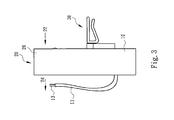
Fig. 3 is a left side view ofFig. 2 ; -
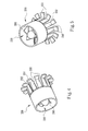
Fig. 4 is a perspective view of the wind speed throttle of the present invention; and -
Fig. 5 is another perspective view ofFig. 4 . - Embodiments of the present invention will now be described, by way of example only, with reference to the accompanying drawings.
- As shown in
Fig. 1 through Fig. 3 , the present invention comprises a negative ion generatormain body 10 to accommodate the negative ion generator. The generative ion generator has a flexiblehigh tension line 11 with a soft carbon brush negativeion emitting end 13. Thehigh tension line 11 and the negativeion emitting end 13 are exposed out of the negative ion generatormain body 10. The soft carbon brush negativeion emitting end 13 is just as an example and not limited, which can be other type of negative ion emitting end, such as a metallic needle. - A wind
power generation device 20 is coupled to the negative ion generatormain body 10. The power cord of the windpower generation device 20 is connected to the negative ion generator. In general, the exposed power cord supplies power to the negative ion generator. The windpower generation device 20 comprisesfan blades 28 which communicate with outside and are turned by the wind power of an external wind source including other power device or fan device to generate the required electricity. - As shown in the drawings, the
fan blades 28 of the windpower generation device 20 are disposed at one side as indicated by the arrow to form a wind receiving side 22 (facing the wind outlet of the wind power source, other power device or fan device). The opposing side as indicated by another arrow is awind sending side 24. - In this embodiment, the
fan blades 28 of the windpower generation device 20 are mounted in a wind guidingroom 26 to guide the wind power from thewind receiving side 22 to thewind sending side 24. - In this embodiment as shown in the drawings, the negative
ion emitting end 13 preferably faces thewind sending side 24 as indicated by the arrow to enhance the diffusion of the negative ions of the device. - The aforesaid embodiment of the present invention further comprises a
positioning device 30 to position the negative ion generatormain body 10 at a desired article or a place. In this embodiment as shown in the drawings, thepositioning device 30 is a clip member coupled to the negative ion generatormain body 10, such that the entire device can be positioned at the wind outlet of an indoor or vehicular electric fan or air conditioner. - The aforesaid positioning device is just as an example, which can be a Velcro, a fastening strip, or a twin adhesive or the like to position the present invention at a desired place.
- Furthermore, the present invention further comprises a voltage regulation (such as, boosting voltage or stabilizing voltage) device for the fan blades when they are turned slowly or for the related circuit to supply power to the negative ion generator.
- Furthermore, the present invention further comprises a wind speed throttle structure for the wind blades to have even power generation when at different rotational speed (high speed or lower speed). As shown in
Fig. 4 and Fig. 5 , the windpower generation device 200 of the present invention comprises the wind speed throttle structure. The opposing side of thewind receiving side 220 of thefan blades 280 is provided with a plurality of spacedresilient claws 250 which are arranged in a circle. Eachresilient claw 250 has aprotrusion 251. Agap 252 is defined between every two adjacentresilient claws 250. When thefan blades 280 are turned at different speeds, the opposing side of thewind receiving side 220 forms different wind resistance structures to achieve the wind speed throttling effect. - The present invention is portable and movable to be installed at different places, such as the cool air outlet of the household or office air conditioner. The negative ion emitting end is adjusted to the required wind power flow direction. The
fan blades 28 of the windpower generation device 20 are driven by the wind power to supply electricity to the negative ion generator for the emittingend 13 to generate negative ions. The present invention can be installed on mobile vehicles, for example, it is installed at the cool air outlet of an automobile. The present invention can be positioned on the exterior of a helmet to generate negative ions by movement of the motor vehicle so as to purify the air. - Although particular embodiments of the present invention have been described in detail for purposes of illustration, various modifications and enhancements may be made without departing from the spirit and scope of the present invention. Accordingly, the present invention is not to be limited except as by the appended claims.
Claims (10)
- A wind power negative ion generator, comprising a negative ion generator main body, the generative ion generator comprising a power line and an exposed negative ion emitting end disposed at an end of a high tension line; at least one wind power generation device coupled to the negative ion generator main body, the wind power generation device having a power cord connected to the power line of the negative ion generator; the wind power generation device comprising fan blades to communicate with outside and form a wind receiving side.
- The wind power negative ion generator as claimed in claim 1, wherein the wind power generation device further has an opposing wind sending side relative to the wind receiving side.
- The wind power negative ion generator as claimed in claim 1 or claim 2, wherein the negative ion generator main body further comprises a positioning device.
- The wind power negative ion generator as claimed in claim 3, wherein the positioning device is one of a clip member, a Velcro, a fastening strip and a twin adhesive.
- The wind power negative ion generator as claimed in any claims of claim 1 to claims 4, wherein the negative ion emitting end is a soft carbon brush.
- The wind power negative ion generator as claimed in any claims of claim 1 to claims 4, wherein the negative ion emitting end is a metallic needle.
- The wind power negative ion generator as claimed in any claims of claim 1 to claims 4, wherein the negative ion generator main body further comprises a voltage regulation device.
- The wind power negative ion generator as claimed in any claims of claim 1 to claims 4, wherein the wind power generation device further comprises a wind speed throttle.
- The wind power negative ion generator as claimed in any claims of claim 1 to claims 4, wherein the fan blades of the wind power generation device are mounted in a wind guiding room.
- The wind power negative ion generator as claimed in any claims of claim 1 to claims 4, wherein the negative ion emitting end faces the wind sending side.
Applications Claiming Priority (1)
| Application Number | Priority Date | Filing Date | Title |
|---|---|---|---|
| TW100221406U TWM432712U (en) | 2011-11-11 | 2011-11-11 | Wind powered negative ion generator |
Publications (1)
| Publication Number | Publication Date |
|---|---|
| EP2591810A1 true EP2591810A1 (en) | 2013-05-15 |
Family
ID=48002086
Family Applications (1)
| Application Number | Title | Priority Date | Filing Date |
|---|---|---|---|
| EP12000377.7A Withdrawn EP2591810A1 (en) | 2011-11-11 | 2012-01-20 | Wind power negative ion generator |
Country Status (4)
| Country | Link |
|---|---|
| US (1) | US20130120895A1 (en) |
| EP (1) | EP2591810A1 (en) |
| JP (1) | JP3174998U (en) |
| TW (1) | TWM432712U (en) |
Families Citing this family (12)
| Publication number | Priority date | Publication date | Assignee | Title |
|---|---|---|---|---|
| JP6157281B2 (en) * | 2013-08-29 | 2017-07-05 | シャープ株式会社 | Ion generator |
| CN103743001A (en) * | 2013-11-20 | 2014-04-23 | 谢虹 | Anion air purifier |
| US10320160B2 (en) | 2014-03-31 | 2019-06-11 | Sharp Kabushiki Kaisha | Ion generation apparatus and electrical equipment |
| USD755360S1 (en) | 2015-03-25 | 2016-05-03 | Naturion Pte. Ltd | Automotive ionizer |
| JP6591823B2 (en) * | 2015-08-05 | 2019-10-16 | シャープ株式会社 | Ion generator and electrical equipment |
| JP6612084B2 (en) * | 2015-08-05 | 2019-11-27 | シャープ株式会社 | Ion generator and electrical equipment |
| JP6526525B2 (en) | 2015-09-02 | 2019-06-05 | シャープ株式会社 | Ion generator, method of manufacturing ion generator, and electric device |
| US10980909B2 (en) | 2016-03-28 | 2021-04-20 | Sharp Kabushiki Kaisha | Ion generating device and method for manufacturing ion generating device |
| CN106562548A (en) * | 2016-11-10 | 2017-04-19 | 成都朵猫文化传播有限公司 | Intelligent electric hair drier |
| FR3072891B1 (en) * | 2017-10-28 | 2019-11-08 | Ancilia Protect Ltd | IONIZER EQUIPPED WITH ION FLOW ACCELERATOR, IN PARTICULAR FOR PROTECTION AGAINST MOSQUITOES |
| CN109237742B (en) * | 2018-08-03 | 2023-09-01 | 美的集团武汉制冷设备有限公司 | Air conditioner, control method thereof, and computer-readable storage medium |
| JP6921434B2 (en) * | 2019-08-30 | 2021-08-18 | 株式会社ベッセル工業 | Static eliminator |
Citations (4)
| Publication number | Priority date | Publication date | Assignee | Title |
|---|---|---|---|---|
| EP1213949A1 (en) * | 2000-12-08 | 2002-06-12 | Illinois Tool Works Inc. | Emitter assembly |
| WO2006031036A1 (en) * | 2004-09-17 | 2006-03-23 | Chang-Min Lee | Negative ion emission lamp |
| EP1906105A2 (en) * | 2006-09-13 | 2008-04-02 | Marley Engineered Products LLC | A fan forced electric unit that incorporates a low power cold plasma generator and method of making the same |
| WO2011049867A2 (en) * | 2009-10-23 | 2011-04-28 | Ventiva, Inc. | Redundant emitter electrodes in an ion wind fan |
Family Cites Families (4)
| Publication number | Priority date | Publication date | Assignee | Title |
|---|---|---|---|---|
| US3873835A (en) * | 1973-11-02 | 1975-03-25 | Vladimir Ignatjev | Ionizer |
| US4253852A (en) * | 1979-11-08 | 1981-03-03 | Tau Systems | Air purifier and ionizer |
| US6772606B2 (en) * | 2002-07-15 | 2004-08-10 | Maytag Corporation | Method and apparatus for a plastic evaporator fan shroud assembly |
| TWI356673B (en) * | 2008-07-30 | 2012-01-11 | Compal Electronics Inc | Fan assembly |
-
2011
- 2011-11-11 TW TW100221406U patent/TWM432712U/en not_active IP Right Cessation
-
2012
- 2012-01-19 US US13/353,369 patent/US20130120895A1/en not_active Abandoned
- 2012-01-20 EP EP12000377.7A patent/EP2591810A1/en not_active Withdrawn
- 2012-01-24 JP JP2012000326U patent/JP3174998U/en not_active Expired - Fee Related
Patent Citations (4)
| Publication number | Priority date | Publication date | Assignee | Title |
|---|---|---|---|---|
| EP1213949A1 (en) * | 2000-12-08 | 2002-06-12 | Illinois Tool Works Inc. | Emitter assembly |
| WO2006031036A1 (en) * | 2004-09-17 | 2006-03-23 | Chang-Min Lee | Negative ion emission lamp |
| EP1906105A2 (en) * | 2006-09-13 | 2008-04-02 | Marley Engineered Products LLC | A fan forced electric unit that incorporates a low power cold plasma generator and method of making the same |
| WO2011049867A2 (en) * | 2009-10-23 | 2011-04-28 | Ventiva, Inc. | Redundant emitter electrodes in an ion wind fan |
Also Published As
| Publication number | Publication date |
|---|---|
| JP3174998U (en) | 2012-04-19 |
| TWM432712U (en) | 2012-07-01 |
| US20130120895A1 (en) | 2013-05-16 |
Similar Documents
| Publication | Publication Date | Title |
|---|---|---|
| EP2591810A1 (en) | Wind power negative ion generator | |
| US9847623B2 (en) | Ion generating device enclosure | |
| US20170232131A1 (en) | Flexible ion generation device | |
| CN205316544U (en) | Air -conditioning outlet negative oxygen ion generating device | |
| WO2016121153A1 (en) | Ion generating device and electrical equipment | |
| CN111237872B (en) | Vortex ring generating device, air conditioner indoor unit and air conditioner | |
| CN202363737U (en) | Wind power generation anion generator | |
| KR200488316Y1 (en) | Portable fan capable of being fixed and being put | |
| CN104159387A (en) | Ion fan for eliminating screen static electricity | |
| JP2004205137A (en) | Air supply grill with negative ion generator | |
| CN219415122U (en) | Air conditioner | |
| KR20200133480A (en) | Multifunctional portable fan | |
| CN211177125U (en) | Air conditioner indoor unit and air conditioner | |
| JP6401020B2 (en) | Ion generator | |
| CN112747367B (en) | Vortex ring generating device, air conditioner indoor unit and air conditioner | |
| JP2004148884A (en) | Ion generator for vehicle air conditioner | |
| CN222576949U (en) | Air-out subassembly and fan | |
| CN214172508U (en) | Electric control cabinet of heating ventilation air conditioner | |
| WO2015002607A1 (en) | Interactive ionizers and methods for providing ions | |
| CN202949132U (en) | Ion generating element and ion generating device having the ion generating element | |
| CN210423087U (en) | Speed-regulating fan | |
| CN213514123U (en) | Air conditioner indoor unit and air conditioner | |
| CN116614594B (en) | Narrow-frame television structure and television | |
| CN217783812U (en) | Driving device, fan lamp with same and air purification lamp | |
| CN208952339U (en) | Limiting wiring structure and air conditioner |
Legal Events
| Date | Code | Title | Description |
|---|---|---|---|
| PUAI | Public reference made under article 153(3) epc to a published international application that has entered the european phase |
Free format text: ORIGINAL CODE: 0009012 |
|
| AK | Designated contracting states |
Kind code of ref document: A1 Designated state(s): AL AT BE BG CH CY CZ DE DK EE ES FI FR GB GR HR HU IE IS IT LI LT LU LV MC MK MT NL NO PL PT RO RS SE SI SK SM TR |
|
| AX | Request for extension of the european patent |
Extension state: BA ME |
|
| STAA | Information on the status of an ep patent application or granted ep patent |
Free format text: STATUS: THE APPLICATION IS DEEMED TO BE WITHDRAWN |
|
| 18D | Application deemed to be withdrawn |
Effective date: 20131116 |