EP2591661A1 - Harvester delivery control system - Google Patents
Harvester delivery control system Download PDFInfo
- Publication number
- EP2591661A1 EP2591661A1 EP12191783.5A EP12191783A EP2591661A1 EP 2591661 A1 EP2591661 A1 EP 2591661A1 EP 12191783 A EP12191783 A EP 12191783A EP 2591661 A1 EP2591661 A1 EP 2591661A1
- Authority
- EP
- European Patent Office
- Prior art keywords
- crop material
- sieve
- distributor
- grain
- actuator
- Prior art date
- Legal status (The legal status is an assumption and is not a legal conclusion. Google has not performed a legal analysis and makes no representation as to the accuracy of the status listed.)
- Granted
Links
Images


Classifications
-
- A—HUMAN NECESSITIES
- A01—AGRICULTURE; FORESTRY; ANIMAL HUSBANDRY; HUNTING; TRAPPING; FISHING
- A01D—HARVESTING; MOWING
- A01D75/00—Accessories for harvesters or mowers
- A01D75/28—Control mechanisms for harvesters or mowers when moving on slopes; Devices preventing lateral pull
- A01D75/282—Control mechanisms for harvesters or mowers when moving on slopes; Devices preventing lateral pull acting on the grain cleaning and separating device
-
- A—HUMAN NECESSITIES
- A01—AGRICULTURE; FORESTRY; ANIMAL HUSBANDRY; HUNTING; TRAPPING; FISHING
- A01F—PROCESSING OF HARVESTED PRODUCE; HAY OR STRAW PRESSES; DEVICES FOR STORING AGRICULTURAL OR HORTICULTURAL PRODUCE
- A01F12/00—Parts or details of threshing apparatus
- A01F12/44—Grain cleaners; Grain separators
- A01F12/446—Sieving means
-
- A—HUMAN NECESSITIES
- A01—AGRICULTURE; FORESTRY; ANIMAL HUSBANDRY; HUNTING; TRAPPING; FISHING
- A01F—PROCESSING OF HARVESTED PRODUCE; HAY OR STRAW PRESSES; DEVICES FOR STORING AGRICULTURAL OR HORTICULTURAL PRODUCE
- A01F12/00—Parts or details of threshing apparatus
- A01F12/44—Grain cleaners; Grain separators
- A01F12/446—Sieving means
- A01F12/448—Sieve adjusting means
Definitions
- the present invention relates generally to a delivery control system for a harvester, and more particularly, to a delivery control system a harvester, such as an agricultural combine for evening the distribution of threshed crops being delivered from the threshing system to the cleaning system of a combine, including when the receiving component of the cleaning system is tilted to accommodate uneven terrain, such as uphill or downhill travel by the combine.
- Combines are used all over the world to harvest many different crops.
- a typical combine configuration utilizes a separation or threshing system including one or more rotors partially or fully surrounded by a perforated concave, wherein threshed crop material will fall through the perforations of the concave en route to a cleaning system operable for separating grain of the threshed crop material from material other than grain (MOG).
- MOG material other than grain
- the present invention relates to an agricultural combine comprising a threshing system.
- a sieve is positioned and configured for receiving crop material containing grain from the threshing system and allowing the grain and smaller elements of the crop material to pass through the sieve while guiding and propelling a flow of larger elements of the crop material past an edge of the sieve.
- a crop material distributor is disposed between the threshing system and the sieve, configured and operable for distributing the crop material from the threshing system onto the sieve.
- a sensor is configured and operable in response to sensing information representative of at least one of a quantity of grain associated with the crop material distributor and an inclination angle associated with the crop material distributor and outputting signals representative thereof.
- An apparatus is operably associated with the crop material distributor, including an actuator configured and controllably operable for positioning the apparatus.
- a control system is connected in operative control of the actuator, and the sensor for receiving the signals outputted thereby, wherein the control system is operable for controlling the position of the actuator for positioning the apparatus.
- the present invention further relates to a retrofit kit for an agricultural combine including an apparatus operably associable with a crop material distributor disposed between a threshing system and a sieve positioned and configured for receiving crop material containing grain from the threshing system and allowing the grain and smaller elements of the crop material to pass through the sieve while guiding and propelling a flow of larger elements of the crop material past an edge of the sieve.
- the apparatus is configured and operable for distributing crop material from the threshing system onto the sieve.
- An actuator is configurable and controllably operable for positioning the apparatus.
- a sensor is configurable and operable for sensing information representative of at least one of a quantity of grain associated with the crop material distributor and an inclination angle associated with the crop material distributor and outputting signals representative thereof.
- a compatible software package is provided for establishing a control system having a controller for providing operative control of the actuator and receiving the signals outputted thereby.
- the control system is operable for controlling the position of the actuator for positioning the apparatus. Mechanical fasteners, electrical wiring and electrical connectors as required for installation of the apparatus, the actuator, the sensor and the control system in the combine.
- the invention yet further relates to a method for distributing crop material onto a cleaning sieve of an agricultural combine.
- the method includes providing at least one sensor configured and operable for sensing information representative of at least one of a quantity of grain associated with the crop material distributor and an inclination angle associated with the crop material distributor, and outputting signals representative thereof.
- the method includes providing a crop material distributor disposed between a threshing system of the combine and the sieve, for distributing crop material from the threshing system generally evenly onto the sieve.
- the method further includes providing an apparatus operably associated with the distributor for controllably distributing crop material onto the sieve.
- the method additionally includes controlling a position of the apparatus as a function of signals from the at least one sensor.
- Grain loss sensors are operable in the conventional, well-known manner, for instance, by sensing electrical capacitance change, for measuring or quantifying the amount of grain loss past the edge of the cleaning sieve, and can be disposed, for instance, adjacent opposite ends of the edge of the sieve, and at one or more intermediate locations therealong, for determining grain losses at those locations, which information can be used for determining a distribution of grain losses across the edge or extent of the sieve.
- Grain loss sensors can be used alone, or with one or more other sensors, for instance, a load sensor, mass sensor, optical sensor, or the like, for determining crop material distribution on or to the cleaning sieve, and/or on or a crop material distributor disposed intermediate the threshing and cleaning systems, such as, a grain pan, sieve, preparation floor, or the like.
- FIG. 1 a typical self-propelled agricultural combine 10 is shown, including a header 12 mounted on a front end thereof, and operable for severing crops from a field during forward motion of combine 10.
- Combine 10 includes a feeder 14 operable for conveying the cut crops to a rotary threshing system 16 within combine 10.
- Threshing system 16 generally includes one or more rotors 18 rotatable within a corresponding number of perforated concaves 20, for threshing and separating smaller elements of crop material including grain from larger elements such as stalks, leaves and the like.
- Flows of the smaller elements of the crop material are discharged through the perforations of concave 20, as denoted generally by arrows A.
- the flows of crop material denoted by arrows A will be uneven, so as to be more concentrated or heavier in some regions, and lighter in other regions, which unevenness will be the result of one or more of a variety of factors, as discussed above.
- distributor 22 disposed beneath threshing system 16, which distributor 22 can comprise a conventionally constructed grain pan operable for conveying crop material rearwardly thereover to a rear edge thereof, over which the crop material will be propelled so as to fall as a mat onto an upper cleaning sieve 24 of a cleaning system 26 of combine 10.
- distributor 22 can comprise a sieve.
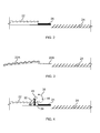
- crop material distributor 22 includes a pre-sieve or shortened sieve 25 connected thereto, after which crop material (not shown) passing over sieve 25 is deposited onto sieve 24. Seed would be separated from MOG as the crop material moves rearward (i.e., from distributor 22 toward sieve 24).
- FIG. 3 another embodiment of crop material distributor 22 includes an auger or auger distributor or auger bed 22A extending to a shortened grain pan 25.
- Grain pan 25 provides a small improvement with respect to grain loss or "dumping" as the crop material moves rearward, such as from uphill travel of the harvester (not shown).
- improvements to further reduce grain loss can be achieved by embodiments, such as discussed in FIGS. 4-6 .
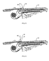
- a control apparatus or flow apparatus or apparatus 32 is pivotably connected to crop material distributor 22 and to an actuator 34, such as a linear actuator.
- apparatus 32 can be positionable, such as by a rotational movement 38 between a first angular position 44 and a second angular position 45 with respect to distributor 22.
- apparatus 32 when positioned at second angular position 45 could approach or coincide with a substantially vertical arrangement that is substantially perpendicular to distributor 22.
- a controller 46 controls the position of apparatus 32.
- controller 46 in response to receiving a signal from a sensor 48, such as an inclinometer generated in response to sensing an inclination angle of sufficient magnitude, urges apparatus 32 into rotational movement 38 in a direction toward the second position 45.
- apparatus 32 As apparatus 32 is rotated toward second position 45, apparatus 32, which extends substantially transversely with respect to distributor 22, similar to a raising drawbridge, provides an increasing impediment with respect to crop material moving toward sieve 25. Alternately, in response to the inclinometer or sensor 48 generating a signal upon sensing a sufficient reduction in the inclination angle, apparatus 32 is rotated in the opposite direction, i.e., rotational movement 38 toward first angular position 44. It is to be understood that the timing and extent, and even speed of such rotational movement may be affected by the previous magnitude, as well as duration of the "uphill" inclination angle, the type of crop material, as well as other factors.
- an actuator 36 such as a rotary actuator, may be used to rotate apparatus 32 between positions of angular movement 38, as previously discussed in FIG. 4 .
- apparatus may be a solid piece of material, in one embodiment, or may contain slots or have openings formed therein in another embodiment.
- apparatus 32 being secured to an actuator 36, such as a linear actuator, which apparatus 32 being positioned above distributor 22.
- Actuator 36 may be secured to inner structure of the harvester in one embodiment, or may be secured to distributor 22 in another embodiment.
- apparatus 32 is urged into axial movement 40 toward distributor 22 by controller 46 in response to controller 46 receiving a signal from inclinometer or sensor 48 that indicates an "uphill" inclination angle as previously discussed above.
- apparatus 32 is urged into axial movement 40 away from distributor 22 by controller 46 in response to controller 46 receiving a signal from inclinometer or sensor 48 that indicates a sufficient reduction in inclination angle as previously discussed above.
- Actuators 34 and 36 which may be linear or rotary actuators, respectively, can be suitably powered, for instance, electrically or fluidly, in the well-known manner.
- the actuators could comprise motors, or the like.
- respective actuator 34, 36 is operatively connected to a single controller 46, which preferably comprises a conventional programmable processor based controller commonly utilized for controlling various combine operations and functions in the well-known manner.
- controller 46 can control actuator 34 for controlling the position of distributor 32 for controlling grain distribution to sieve 24 as a function of a desired parameter according to the present invention, which here has been selected to be grain loss.
- system 11 comprises controller 46, but it should be recognized that controller 46 can perform a variety of other functions, including, but not limited to, cleaning system leveling.
- System 11 additionally is illustrated as comprising an optional input device 50, which can be for instance, an interactive device such as a touch screen or the like, or a switch, connected to controller 46 and located within an operator cab 52 of combine 10, usable for inputting positional and other commands to system 11, and optionally for viewing system information.
- System 11 preferably also comprises at least one sensor operable for sensing or detecting a condition indicative of performance thereof, and/or the effects of performance thereof, to facilitate monitoring and controlling operation thereof, which, in this embodiment of the system, includes at least two grain loss detectors 54 and 56 disposed adjacent opposite ends of, or at spaced apart locations along, rear edge 28 of sieve 24.
- Controller 46 is connected to actuator 34; to actuator 36, if present (if a cleaning system leveling capability is provided); to input device 50; and to grain loss detectors 54 and 56, via suitable conductive paths 58, which can include, for instance, but are not limited to, wires of a wiring harness, and/or one or more communications networks, such as a controller area network.
- Controller 46 is automatically operable for controlling the position of apparatus 32 as a function of system 11, and at least sieve 24 of cleaning system 26 (sieves 24 and 30 being jointly or separately controllable, as desired for a particular application) as a function of the distribution system.
- threshing system 16 will discharge crop material at higher rates, or in heavier concentrations, from some regions of concave 20 compared to others. This can occur for a variety of reasons, such as, but not limited to, crop type, population, and moisture content, and can vary at least somewhat over the course of a harvesting episode.
- controller 46 of system 11 is automatically operable for determining a position of apparatus 32, such as between a first angular position 44 and a second angular position 45 with respect to crop material distributor 22 required for distributing crop material flow to cleaning system 26, in an ongoing manner, in real-time, or near real-time, responsive to a sensed condition or conditions indicative of performance and/or another selected parameter, which here is grain loss, as sensed by grain loss detectors 54 and 56.
- the angular orientation of apparatus 32 can also be set by an operator, via commands inputted using input device 50.
- System 11 can then automatically operate to maintain a performance parameter achieved by the inputted setting, for instance, a satisfactory or set grain loss level, and can operate to even out the grain loss between the two sides of the cleaning system, as a function of comparison of the signals from grain loss sensors 54 and 56, and setting opposed ends of apparatus 32 at different height levels by respective actuators 34 (only one actuator 34 shown in FIG. 4 ).
- a performance parameter achieved by the inputted setting for instance, a satisfactory or set grain loss level
- System 11 can automatically detect this.
- Controller 46 can then responsively make appropriate adjustments to the positions of the opposed ends of apparatus 32 via respective actuators 34, as required.
- FIG. 8 is a high level flow diagram 60 illustrating steps of one possible method of operation of system 11 for controlling the position of apparatus 32 of distributor 22.
- a distributor inclination angle will be determined. This can be via an automatic process as controlled by controller 46, responsive to a desired parameter, such as grain loss, and the above-described manner (inclinometer or sensor 48). Alternatively, this could be responsive to a manually inputted command, via input device 50. Controller 46 would then either automatically control apparatus 32 for controlling the control parameter, e.g., grain loss, or for maintaining the inputted position.
- the inclination angle is determined whether it is outside of an acceptable range, such as, for example, within 5 degrees from a horizontal plane.
- control of the method is returned to block 62 to again determine the inclination angle of the crop material distributor.
- method proceeds to block 66 which actuates flow apparatus 32 for a predetermined period of time.
- the predetermined period of time is a fixed period of time, such as 5 seconds, or in another embodiment the predetermined time may depend upon the magnitude of the inclination angle, i.e., the magnitude of the amount inclination angle is outside of the acceptable range. Stated another way, the greater the magnitude of the inclination angle, the greater the extent of movement or "blockage" of crop material by flow apparatus 32.
- the controller Upon completion of block 66, at block 68 the controller returns flow apparatus 32 to its default or centered position, with control of the method returning to block 62 to repeat the method.
- signals from other sensors 42 FIGS. 1 , 7
- sensors associated with quantity of grain measurement including a weight of crop material positioned on the crop material distributor or sensors associated with measurement of structural loading on a system drive component
- sensors associated with measurement of structural loading on system drive components may be utilized. That is, if grain sensors indicated that excessive grain loss were still occurring, flow apparatus 32 would not yet be returned to the default position.
- Controller 46 can be programmed to automatically adjust for such sensor readings, on an ongoing basis, in real-time, or near real-time, to maintain the control parameter, or the commanded position of apparatus 32 in relation to a fixed reference, such as horizontal, so as to maintain system performance.
- a retrofit kit for an agricultural combine could be created that includes apparatus 32 which is operably associable with crop material distributor 22.
- Distributor 22 is disposed between threshing system 16 and sieve 24 positioned and configured for receiving crop material containing grain from the threshing system and allowing the grain and smaller elements of the crop material to pass through the sieve while guiding and propelling a flow of larger elements of the crop material past edge 28 of the sieve.
- Apparatus 32 is configured and operable for distributing crop material from threshing system 16 onto sieve 24.
- An actuator, such as actuator 34, 36 is configurable and controllably operable for positioning apparatus 32.
- a sensor such as sensor 42 is configurable and operable for sensing information representative of at least one of a quantity of grain associated with crop material distributor 22 and an inclination angle associated with the crop material distributor and outputting signals representative thereof.
- a compatible software package (not shown) is provided for establishing a control system providing operative control of the actuator. It is to be understood that a software package can include an upgrade or a portion of software code that can be uploaded into existing software of a combine in a well known manner. In one embodiment, the software may already be included in the controller, or in another embodiment, the software may be included in components insertable, whether temporarily or permanently, into the controller, such as a memory chip or circuit board or the like.
- the software installed in the controller is then configured for receiving the signals outputted thereby, such that the control system is operable for controlling the position of the actuator for positioning the apparatus.
- Mechanical fasteners, electrical wiring and electrical connectors (not shown) as required for installation of the apparatus that is well known, the actuator, the sensor and the control system in the combine.
Landscapes
- Life Sciences & Earth Sciences (AREA)
- Environmental Sciences (AREA)
- Threshing Machine Elements (AREA)
- Harvester Elements (AREA)
Abstract
Description
- The present invention relates generally to a delivery control system for a harvester, and more particularly, to a delivery control system a harvester, such as an agricultural combine for evening the distribution of threshed crops being delivered from the threshing system to the cleaning system of a combine, including when the receiving component of the cleaning system is tilted to accommodate uneven terrain, such as uphill or downhill travel by the combine.
- Combines are used all over the world to harvest many different crops. A typical combine configuration utilizes a separation or threshing system including one or more rotors partially or fully surrounded by a perforated concave, wherein threshed crop material will fall through the perforations of the concave en route to a cleaning system operable for separating grain of the threshed crop material from material other than grain (MOG). Often, due to the combine encountering uneven terrain, such as encountered during uphill and downhill travel, the rate of discharge of this threshed crop material from the separating system to the cleaning system can widely fluctuate. For example, the rate of discharged crop material can be temporarily reduced or interrupted during downhill travel, with an opposite effect occurring during uphill travel. A significant problem that can result from uneven distribution of crop material to the cleaning system is increased grain loss resulting from overloading of regions of the cleaning system sieve or sieves.
- In light of the capabilities and limitations of the apparatus discussed above for distributing crop material delivery to a cleaning system of a combine, what is sought is a system and method which allows optimizing this capability for accommodating both uneven threshing system output, and uneven terrain, particularly uphill and downhill travel conditions.
- Other features and advantages of the present invention will be apparent from the following more detailed description of the preferred embodiment, taken in conjunction with the accompanying drawings which illustrate, by way of example, the principles of the invention.
- The present invention relates to an agricultural combine comprising a threshing system. A sieve is positioned and configured for receiving crop material containing grain from the threshing system and allowing the grain and smaller elements of the crop material to pass through the sieve while guiding and propelling a flow of larger elements of the crop material past an edge of the sieve. A crop material distributor is disposed between the threshing system and the sieve, configured and operable for distributing the crop material from the threshing system onto the sieve. A sensor is configured and operable in response to sensing information representative of at least one of a quantity of grain associated with the crop material distributor and an inclination angle associated with the crop material distributor and outputting signals representative thereof. An apparatus is operably associated with the crop material distributor, including an actuator configured and controllably operable for positioning the apparatus. A control system is connected in operative control of the actuator, and the sensor for receiving the signals outputted thereby, wherein the control system is operable for controlling the position of the actuator for positioning the apparatus.
- The present invention further relates to a retrofit kit for an agricultural combine including an apparatus operably associable with a crop material distributor disposed between a threshing system and a sieve positioned and configured for receiving crop material containing grain from the threshing system and allowing the grain and smaller elements of the crop material to pass through the sieve while guiding and propelling a flow of larger elements of the crop material past an edge of the sieve. The apparatus is configured and operable for distributing crop material from the threshing system onto the sieve. An actuator is configurable and controllably operable for positioning the apparatus. A sensor is configurable and operable for sensing information representative of at least one of a quantity of grain associated with the crop material distributor and an inclination angle associated with the crop material distributor and outputting signals representative thereof. A compatible software package is provided for establishing a control system having a controller for providing operative control of the actuator and receiving the signals outputted thereby. The control system is operable for controlling the position of the actuator for positioning the apparatus. Mechanical fasteners, electrical wiring and electrical connectors as required for installation of the apparatus, the actuator, the sensor and the control system in the combine.
- The invention yet further relates to a method for distributing crop material onto a cleaning sieve of an agricultural combine. The method includes providing at least one sensor configured and operable for sensing information representative of at least one of a quantity of grain associated with the crop material distributor and an inclination angle associated with the crop material distributor, and outputting signals representative thereof. The method includes providing a crop material distributor disposed between a threshing system of the combine and the sieve, for distributing crop material from the threshing system generally evenly onto the sieve. The method further includes providing an apparatus operably associated with the distributor for controllably distributing crop material onto the sieve. The method additionally includes controlling a position of the apparatus as a function of signals from the at least one sensor.
- Grain loss sensors are operable in the conventional, well-known manner, for instance, by sensing electrical capacitance change, for measuring or quantifying the amount of grain loss past the edge of the cleaning sieve, and can be disposed, for instance, adjacent opposite ends of the edge of the sieve, and at one or more intermediate locations therealong, for determining grain losses at those locations, which information can be used for determining a distribution of grain losses across the edge or extent of the sieve. Grain loss sensors can be used alone, or with one or more other sensors, for instance, a load sensor, mass sensor, optical sensor, or the like, for determining crop material distribution on or to the cleaning sieve, and/or on or a crop material distributor disposed intermediate the threshing and cleaning systems, such as, a grain pan, sieve, preparation floor, or the like.
- Numerous other features and advantages of the present invention will become readily apparent from the following detailed description, the accompanying drawings, and the appended claims.
-
-
FIG. 1 is a side view of an agricultural combine, including a system for controllably delivering crop material to a distribution system of the combine, according to the present invention. -
FIGS. 2-6 are partial side views of different embodiments of distribution systems according to the present invention. -
FIG. 7 is a schematic representation of an embodiment of a distribution system according to the present invention. -
FIG. 8 is a flow diagram of an embodiment of a distribution system according to the present invention. - Numerous other features and advantages of the present invention will become readily apparent from the following detailed description, the accompanying drawings, and the appended claims.
- Referring now to the drawings, wherein preferred embodiments of the present invention are shown, in
FIG. 1 , a typical self-propelledagricultural combine 10 is shown, including aheader 12 mounted on a front end thereof, and operable for severing crops from a field during forward motion ofcombine 10.Combine 10 includes afeeder 14 operable for conveying the cut crops to arotary threshing system 16 withincombine 10.Threshing system 16 generally includes one ormore rotors 18 rotatable within a corresponding number ofperforated concaves 20, for threshing and separating smaller elements of crop material including grain from larger elements such as stalks, leaves and the like. Flows of the smaller elements of the crop material are discharged through the perforations of concave 20, as denoted generally by arrows A. Generally, the flows of crop material denoted by arrows A will be uneven, so as to be more concentrated or heavier in some regions, and lighter in other regions, which unevenness will be the result of one or more of a variety of factors, as discussed above. - The flows of crop material, denoted by arrows A, will fall mostly onto a
crop material distributor 22 disposed beneaththreshing system 16, whichdistributor 22 can comprise a conventionally constructed grain pan operable for conveying crop material rearwardly thereover to a rear edge thereof, over which the crop material will be propelled so as to fall as a mat onto anupper cleaning sieve 24 of acleaning system 26 ofcombine 10. Alternatively,distributor 22 can comprise a sieve. As the crop material mat drops ontoupper cleaning sieve 24, that sieve will be vibrated while a flow of air is directed upwardly and rearwardly therethrough, as denoted by arrows B, such that larger, lighter elements of the crop material other than grain will be directed over or past arear edge 28 ofsieve 24, for disposal, in the well-known manner. Smaller, heavier elements of the crop material, including grain, will be allowed to pass downwardly throughsieve 24 to alower sieve 30, for further cleaning, again, in the well known manner. - As shown in
FIG. 2 ,crop material distributor 22 includes a pre-sieve or shortenedsieve 25 connected thereto, after which crop material (not shown) passing oversieve 25 is deposited ontosieve 24. Seed would be separated from MOG as the crop material moves rearward (i.e., fromdistributor 22 toward sieve 24). - As shown in
FIG. 3 , another embodiment ofcrop material distributor 22 includes an auger or auger distributor orauger bed 22A extending to a shortenedgrain pan 25. Grainpan 25 provides a small improvement with respect to grain loss or "dumping" as the crop material moves rearward, such as from uphill travel of the harvester (not shown). However, improvements to further reduce grain loss can be achieved by embodiments, such as discussed inFIGS. 4-6 . - As shown in
FIGS. 4-5 , a control apparatus or flow apparatus orapparatus 32 is pivotably connected tocrop material distributor 22 and to anactuator 34, such as a linear actuator. As further shownFIG. 4 ,apparatus 32 can be positionable, such as by arotational movement 38 between a firstangular position 44 and a secondangular position 45 with respect todistributor 22. In an alternate embodiment,apparatus 32 when positioned at secondangular position 45 could approach or coincide with a substantially vertical arrangement that is substantially perpendicular todistributor 22. In other words, in an effort to reduce a "surge" of crop material, such as associated with the harvester encountering uphill terrain of sufficient magnitude to urge an amount of crop material too large for the cleaning system of the combine to properly handle, the crop material moving alongdistributor 22 towardsieve 25, acontroller 46 controls the position ofapparatus 32. For example, as shown inFIGS. 4 and7 ,controller 46, in response to receiving a signal from asensor 48, such as an inclinometer generated in response to sensing an inclination angle of sufficient magnitude, urgesapparatus 32 intorotational movement 38 in a direction toward thesecond position 45. Asapparatus 32 is rotated towardsecond position 45,apparatus 32, which extends substantially transversely with respect todistributor 22, similar to a raising drawbridge, provides an increasing impediment with respect to crop material moving towardsieve 25. Alternately, in response to the inclinometer orsensor 48 generating a signal upon sensing a sufficient reduction in the inclination angle,apparatus 32 is rotated in the opposite direction, i.e.,rotational movement 38 toward firstangular position 44. It is to be understood that the timing and extent, and even speed of such rotational movement may be affected by the previous magnitude, as well as duration of the "uphill" inclination angle, the type of crop material, as well as other factors. - As shown in
FIG. 5 , anactuator 36, such as a rotary actuator, may be used to rotateapparatus 32 between positions ofangular movement 38, as previously discussed inFIG. 4 . It is to be understood that apparatus may be a solid piece of material, in one embodiment, or may contain slots or have openings formed therein in another embodiment. - As shown in
FIG. 6 , another embodiment of the system includesapparatus 32 being secured to anactuator 36, such as a linear actuator, whichapparatus 32 being positioned abovedistributor 22.Actuator 36 may be secured to inner structure of the harvester in one embodiment, or may be secured todistributor 22 in another embodiment. With either attaching arrangement,apparatus 32 is urged intoaxial movement 40 towarddistributor 22 bycontroller 46 in response tocontroller 46 receiving a signal from inclinometer orsensor 48 that indicates an "uphill" inclination angle as previously discussed above. Conversely,apparatus 32 is urged intoaxial movement 40 away fromdistributor 22 bycontroller 46 in response tocontroller 46 receiving a signal from inclinometer orsensor 48 that indicates a sufficient reduction in inclination angle as previously discussed above. -
Actuators - In exemplary embodiments of harvester or combine 10 shown in
FIGS. 1 ,4 ,5 ,respective actuator single controller 46, which preferably comprises a conventional programmable processor based controller commonly utilized for controlling various combine operations and functions in the well-known manner. In this regard,controller 46 can controlactuator 34 for controlling the position ofdistributor 32 for controlling grain distribution to sieve 24 as a function of a desired parameter according to the present invention, which here has been selected to be grain loss. Thus,system 11 comprisescontroller 46, but it should be recognized thatcontroller 46 can perform a variety of other functions, including, but not limited to, cleaning system leveling.System 11 additionally is illustrated as comprising anoptional input device 50, which can be for instance, an interactive device such as a touch screen or the like, or a switch, connected tocontroller 46 and located within anoperator cab 52 ofcombine 10, usable for inputting positional and other commands tosystem 11, and optionally for viewing system information.System 11 preferably also comprises at least one sensor operable for sensing or detecting a condition indicative of performance thereof, and/or the effects of performance thereof, to facilitate monitoring and controlling operation thereof, which, in this embodiment of the system, includes at least two grain loss detectors 54 and 56 disposed adjacent opposite ends of, or at spaced apart locations along,rear edge 28 ofsieve 24. -
Controller 46 is connected toactuator 34; to actuator 36, if present (if a cleaning system leveling capability is provided); to inputdevice 50; and to grain loss detectors 54 and 56, via suitableconductive paths 58, which can include, for instance, but are not limited to, wires of a wiring harness, and/or one or more communications networks, such as a controller area network. -
Controller 46 is automatically operable for controlling the position ofapparatus 32 as a function ofsystem 11, and atleast sieve 24 of cleaning system 26 (sieves system 16 will discharge crop material at higher rates, or in heavier concentrations, from some regions of concave 20 compared to others. This can occur for a variety of reasons, such as, but not limited to, crop type, population, and moisture content, and can vary at least somewhat over the course of a harvesting episode. This can also occur, at least in part, as a result of combine settings, such as, but not limited to, a speed of operation ofrotor 18, and a gap betweenrotor 18 and concave 20. This is undesirable, as also explained above, as it can affect the performance of cleaningsystem 26, particularly the amount of grain loss, as heavy build ups of crop material, particularly onupper sieve 24, can result in increased grain loss over or pastrear edge 28. A problem identified above in this regard is that crop material build ups and concentrations ondistributor 22 will typically be conveyed ontoupper sieve 24. Sideward tilting of the combine can also result in increased crop material concentrations and build ups, with Applicant'sUS Pat. No. 7,771,260 , as previously mentioned, configured to address such sideward tilting, such as associated with the combine laterally traversing a slope of a hill. - As further shown in
FIGS. 1 and4 ,controller 46 ofsystem 11 is automatically operable for determining a position ofapparatus 32, such as between a firstangular position 44 and a secondangular position 45 with respect tocrop material distributor 22 required for distributing crop material flow to cleaningsystem 26, in an ongoing manner, in real-time, or near real-time, responsive to a sensed condition or conditions indicative of performance and/or another selected parameter, which here is grain loss, as sensed by grain loss detectors 54 and 56. The angular orientation ofapparatus 32 can also be set by an operator, via commands inputted usinginput device 50.System 11 can then automatically operate to maintain a performance parameter achieved by the inputted setting, for instance, a satisfactory or set grain loss level, and can operate to even out the grain loss between the two sides of the cleaning system, as a function of comparison of the signals from grain loss sensors 54 and 56, and setting opposed ends ofapparatus 32 at different height levels by respective actuators 34 (only oneactuator 34 shown inFIG. 4 ). Thus, if grain distribution from the threshing system changes, for instance, as a function of any of the factors discussed above, and grain loss from one side of the cleaning system exceeds loss from the other side by a certain amount,system 11 can automatically detect this.Controller 46 can then responsively make appropriate adjustments to the positions of the opposed ends ofapparatus 32 viarespective actuators 34, as required. -
FIG. 8 is a high level flow diagram 60 illustrating steps of one possible method of operation ofsystem 11 for controlling the position ofapparatus 32 ofdistributor 22. According to the method, atblock 62, a distributor inclination angle will be determined. This can be via an automatic process as controlled bycontroller 46, responsive to a desired parameter, such as grain loss, and the above-described manner (inclinometer or sensor 48). Alternatively, this could be responsive to a manually inputted command, viainput device 50.Controller 46 would then either automatically controlapparatus 32 for controlling the control parameter, e.g., grain loss, or for maintaining the inputted position. As part of its cleaning system crop distribution function, atblock 64 the inclination angle is determined whether it is outside of an acceptable range, such as, for example, within 5 degrees from a horizontal plane. If the inclination angle is not determined to be outside of an acceptable range, control of the method is returned to block 62 to again determine the inclination angle of the crop material distributor. However, if the inclination angle is determined to be outside of an acceptable range, method proceeds to block 66 which actuatesflow apparatus 32 for a predetermined period of time. In one embodiment the predetermined period of time is a fixed period of time, such as 5 seconds, or in another embodiment the predetermined time may depend upon the magnitude of the inclination angle, i.e., the magnitude of the amount inclination angle is outside of the acceptable range. Stated another way, the greater the magnitude of the inclination angle, the greater the extent of movement or "blockage" of crop material byflow apparatus 32. Upon completion ofblock 66, atblock 68 the controller returns flowapparatus 32 to its default or centered position, with control of the method returning to block 62 to repeat the method. In another embodiment, signals from other sensors 42 (FIGS. 1 ,7 ), such as sensors associated with quantity of grain measurement, including a weight of crop material positioned on the crop material distributor or sensors associated with measurement of structural loading on a system drive component, may also be utilized to control the position offlow apparatus 32. Additionally sensors associated with measurement of structural loading on system drive components may be utilized. That is, if grain sensors indicated that excessive grain loss were still occurring,flow apparatus 32 would not yet be returned to the default position.Controller 46 can be programmed to automatically adjust for such sensor readings, on an ongoing basis, in real-time, or near real-time, to maintain the control parameter, or the commanded position ofapparatus 32 in relation to a fixed reference, such as horizontal, so as to maintain system performance. - It is to be understood that a retrofit kit for an agricultural combine could be created that includes
apparatus 32 which is operably associable withcrop material distributor 22.Distributor 22 is disposed between threshingsystem 16 andsieve 24 positioned and configured for receiving crop material containing grain from the threshing system and allowing the grain and smaller elements of the crop material to pass through the sieve while guiding and propelling a flow of larger elements of the crop material pastedge 28 of the sieve.Apparatus 32 is configured and operable for distributing crop material from threshingsystem 16 ontosieve 24. An actuator, such asactuator positioning apparatus 32. A sensor, such assensor 42 is configurable and operable for sensing information representative of at least one of a quantity of grain associated withcrop material distributor 22 and an inclination angle associated with the crop material distributor and outputting signals representative thereof. A compatible software package (not shown) is provided for establishing a control system providing operative control of the actuator. It is to be understood that a software package can include an upgrade or a portion of software code that can be uploaded into existing software of a combine in a well known manner. In one embodiment, the software may already be included in the controller, or in another embodiment, the software may be included in components insertable, whether temporarily or permanently, into the controller, such as a memory chip or circuit board or the like. The software installed in the controller is then configured for receiving the signals outputted thereby, such that the control system is operable for controlling the position of the actuator for positioning the apparatus. Mechanical fasteners, electrical wiring and electrical connectors (not shown) as required for installation of the apparatus that is well known, the actuator, the sensor and the control system in the combine. - While the invention has been described with reference to a preferred embodiment, it will be understood by those skilled in the art that various changes may be made and equivalents may be substituted for elements thereof without departing from the scope of the invention as defined by the appended claims. In addition, many modifications may be made to adapt a particular situation without departing from this essential scope. Therefore, it is intended that the invention not be limited to the particular embodiment disclosed as the best mode contemplated for carrying out this invention, but that the invention will include all embodiments falling within the scope of the appended claims.
Claims (11)
- An agricultural combine (10) comprising:a threshing system (16);a sieve (24) positioned and configured for receiving crop material containing grain from the threshing system (16) and allowing the grain and smaller elements of the crop material to pass through the sieve (24) while guiding and propelling a flow of larger elements of the crop material past an edge of the sieve (24);a crop material distributor (22) disposed between the threshing system (16) and the sieve (24), configured and operable for distributing the crop material from the threshing system (16) onto the sieve (24); anda sensor (42, 48) configured and operable in response to sensing information representative of at least one of a quantity of grain associated with the crop material distributor (22) and an inclination angle associated with the crop material distributor (22) and outputting signals representative thereof,characterized in that the combine (10) further comprises:an apparatus (32) operably associated with the crop material distributor (22), including an actuator (34) configured and controllably operable for positioning the apparatus (32); anda control system (46) connected in operative control of the actuator (34), and the sensor (42, 48) for receiving the signals outputted thereby, wherein the control system (46) is operable for controlling the position of the actuator (34) for positioning the apparatus (32).
- The agricultural combine of Claim 1, wherein the apparatus (32) is positioned in close proximity with an end of the crop material distributor (22) that is near the sieve (24).
- The agricultural combine of Claim 1 or 2, wherein sensing information representative of a quantity of grain includes a depth of crop material positioned on the crop material distributor (22).
- The agricultural combine of Claim 1, 2 or 3, wherein sensing information representative of a quantity of grain includes a weight of crop material positioned on the crop material distributor (22).
- The agricultural combine of any one of the claims 1 to 4, wherein sensing information representative of a quantity of grain includes a measurement of structural loading on a system drive component.
- The agricultural combine of any one of the claims 1 to 5, wherein the system includes an actuator (34) pivotably connected between the distributor (22) and the apparatus (32) to urge the apparatus (32) between a first angular position (44) and a second angular position (45) with respect to the distributor (22).
- The agricultural combine of any one of the claims 1 to 5, wherein the system includes an actuator (34) connected between the distributor (22) and the apparatus (32) to urge the apparatus (32) between a first axial position and a second axial position with respect to the distributor (22).
- The agricultural combine of Claim 7, wherein the actuator (34) is secured to the combine (10) into the distributor (22).
- A retrofit kit for an agricultural combine (10), characterized in that it comprises:an apparatus (32) operably associable with a crop material distributor (22) disposed between a threshing system (16) and a sieve (24) positioned and configured for receiving crop material containing grain from the threshing system (16) and allowing the grain and smaller elements of the crop material to pass through the sieve (24) while guiding and propelling a flow of larger elements of the crop material past an edge of the sieve (24), the apparatus (32) being configured and operable for distributing crop material from the threshing system (16) onto the sieve (24);an actuator (34) configurable and controllably operable for positioning the apparatus (32);a sensor (42, 48) configurable and operable for sensing information representative of at least one of a quantity of grain associated with the crop material distributor (22) and an inclination angle associated with the crop material distributor (22) and outputting signals representative thereof;a compatible software package for establishing a control system having a controller (46) for providing operative control of the actuator (34) and receiving the signals outputted thereby, wherein the control system is operable for controlling the position of the actuator (34) for positioning the apparatus (32); andmechanical fasteners, electrical wiring (58) and electrical connectors as required for installation of the apparatus (32), the actuator (34), the sensor (42, 48) and the control system in the combine (10).
- A method for distributing crop material onto a cleaning sieve (24) of an agricultural combine (10), comprising steps of:providing at least one sensor (42, 48) configured and operable for sensing information representative of at least one of a quantity of grain associated with the crop material distributor (22) and an inclination angle associated with the crop material distributor (22), and outputting signals representative thereof; andproviding a crop material distributor (22) disposed between a threshing system (16) of the combine (10) and the sieve (24), for distributing crop material from the threshing system (16) generally evenly onto the sieve (24);characterized in that the method further comprises:providing an apparatus (32) operably associated with the distributor (22) for controllably distributing crop material onto the sieve (24); andcontrolling a position of the apparatus (32) as a function of signals from the at least one sensor (42, 48).
- The method of Claim 10, wherein providing the apparatus (32) includes positioning the apparatus (32) in close proximity with an end of the crop material distributor (22) that is near the sieve (24).
Applications Claiming Priority (1)
| Application Number | Priority Date | Filing Date | Title |
|---|---|---|---|
| US13/292,591 US9814184B2 (en) | 2011-11-09 | 2011-11-09 | Crop material flow control system |
Publications (2)
| Publication Number | Publication Date |
|---|---|
| EP2591661A1 true EP2591661A1 (en) | 2013-05-15 |
| EP2591661B1 EP2591661B1 (en) | 2018-08-08 |
Family
ID=47225993
Family Applications (1)
| Application Number | Title | Priority Date | Filing Date |
|---|---|---|---|
| EP12191783.5A Active EP2591661B1 (en) | 2011-11-09 | 2012-11-08 | Harvester delivery control system |
Country Status (2)
| Country | Link |
|---|---|
| US (1) | US9814184B2 (en) |
| EP (1) | EP2591661B1 (en) |
Cited By (1)
| Publication number | Priority date | Publication date | Assignee | Title |
|---|---|---|---|---|
| US10039236B2 (en) * | 2015-05-29 | 2018-08-07 | Cnh Industrial America Llc | Grain cleaning system having improved air flow and additional fall step to improve grain cleaning performance |
Families Citing this family (13)
| Publication number | Priority date | Publication date | Assignee | Title |
|---|---|---|---|---|
| GB2487196A (en) * | 2011-01-11 | 2012-07-18 | Agco As | Combine harvester grain cleaning apparatus |
| GB201221347D0 (en) * | 2012-11-28 | 2013-01-09 | Agco As | Crop processing apparatus in a combine harvester |
| CN208462428U (en) * | 2015-08-28 | 2019-02-05 | 凯斯纽荷兰(中国)管理有限公司 | agricultural harvester |
| US10512217B2 (en) * | 2017-08-23 | 2019-12-24 | Deere & Company | Metering flow of grain to a cleaning device |
| CN108650975B (en) * | 2018-03-20 | 2021-07-20 | 江苏大学 | Automatic uniform distribution device and automatic adjustment method of harvester exudates |
| US10966371B2 (en) | 2018-11-05 | 2021-04-06 | Cnh Industrial America Llc | Cleaning system for a combine |
| DE102019125500A1 (en) * | 2019-09-23 | 2021-03-25 | Claas Selbstfahrende Erntemaschinen Gmbh | Cleaning device on a combine harvester |
| DE102020113658A1 (en) * | 2020-05-20 | 2021-11-25 | Claas Selbstfahrende Erntemaschinen Gmbh | Sensor system for the detection of elements of a crop flow |
| DE102020113667A1 (en) * | 2020-05-20 | 2021-11-25 | Claas Selbstfahrende Erntemaschinen Gmbh | Combine harvester with a sensor system |
| GB202016997D0 (en) * | 2020-10-27 | 2020-12-09 | Agco Int Gmbh | Combine harvester having an adjustable stratification pan, and related methods |
| US20240172589A1 (en) * | 2021-03-29 | 2024-05-30 | Agco Corporation | Methods of Detecting Foreign Objects in Crop Material, and Related Harvesting Machines |
| US12324372B2 (en) * | 2021-12-22 | 2025-06-10 | Cnh Industrial America Llc | Agricultural harvester with shakeable positive transport conveyor |
| GB202212331D0 (en) * | 2022-08-24 | 2022-10-05 | Agco Int Gmbh | A grain cleaning apparatus for a combine harvester |
Citations (5)
| Publication number | Priority date | Publication date | Assignee | Title |
|---|---|---|---|---|
| US4875889A (en) * | 1987-10-05 | 1989-10-24 | Deere & Company | Combine crop material flow adjustment system |
| US4897071A (en) * | 1987-10-22 | 1990-01-30 | Ford New Holland, Inc. | Combine harvester cleaning apparatus |
| EP0459109A2 (en) * | 1990-05-25 | 1991-12-04 | Claas Ohg | Apparatus for evenly distributing crop in a combine harvester |
| EP1595435A1 (en) * | 2004-05-11 | 2005-11-16 | CLAAS Selbstfahrende Erntemaschinen GmbH | Cleaning device for a combine |
| EP1958495A1 (en) * | 2007-02-13 | 2008-08-20 | CNH Belgium N.V. | Distribution levelling for an agricultural combine |
Family Cites Families (22)
| Publication number | Priority date | Publication date | Assignee | Title |
|---|---|---|---|---|
| US1064440A (en) | 1912-03-11 | 1913-06-10 | Robert Brown | Grain-cleaner for harvesters. |
| US1243284A (en) * | 1917-08-06 | 1917-10-16 | Austin S Goodman | Grain-separator. |
| US2542346A (en) | 1947-03-19 | 1951-02-20 | Leo J Zimmer | Adjustable feeder for grain pans for grain combines |
| US3108064A (en) | 1961-02-20 | 1963-10-22 | Massey Ferguson Ltd | Grain feeding attachment for hillside operation of a combine |
| US3626472A (en) * | 1969-01-09 | 1971-12-07 | Sperry Rand Corp | Means for feeding crop material to an axial flow threshing and separating combine |
| US3757797A (en) * | 1969-04-22 | 1973-09-11 | B Mathews | Combine |
| JPS60152601U (en) | 1984-03-15 | 1985-10-11 | 株式会社 ほくさん | Continuous liver slice freezing device |
| US4557276A (en) | 1984-10-11 | 1985-12-10 | Sperry Corporation | Four way leveling mechanism for combine cleaning apparatus |
| US4548214A (en) | 1984-10-11 | 1985-10-22 | Sperry Corporation | Fore-and-aft leveling mechanism for combine cleaning apparatus |
| CA1225899A (en) * | 1985-12-02 | 1987-08-25 | Cliff Usick | Attachment for the cleaning sieve of a combine harvester |
| US5021029A (en) | 1989-11-01 | 1991-06-04 | Cliff Usick | Grain saver attachment for the straw walker of a combine |
| US5338257A (en) | 1992-05-29 | 1994-08-16 | Probe Adventures, Inc. | Combine sieve distributor apparatus |
| US5282771A (en) | 1992-05-29 | 1994-02-01 | Probe Adventures, Inc. | Combine sieve levelling apparatus |
| US5527219A (en) * | 1993-07-29 | 1996-06-18 | Schumacher; Gustav | Cleaning sieve for the harvested crop of agricultural machines |
| AT401596B (en) * | 1994-05-27 | 1996-10-25 | Wintersteiger Gmbh & Co | SCREENING DEVICE FOR A COMBINE, IN PARTICULAR FOR A TEST FIELD COMBINE |
| US5791986A (en) * | 1996-12-30 | 1998-08-11 | Deere & Company | Combine ripple pan |
| US6066045A (en) * | 1998-08-06 | 2000-05-23 | Noomen; Wayne | Combine tray lift |
| US6458031B1 (en) * | 2000-01-18 | 2002-10-01 | Case Corporation | Cleaning system for a rotary combine |
| DE10111531A1 (en) * | 2001-03-10 | 2002-09-26 | Deere & Co | Screen for a combine harvester |
| BRPI0413633A (en) | 2003-08-19 | 2006-10-17 | James Straeter | airflow controlled combine and threshing machine shoe |
| GB0408931D0 (en) * | 2004-04-22 | 2004-05-26 | Cnh Belgium Nv | Method for operating a grain cleaning system in a combine harvester |
| US8282453B1 (en) * | 2011-05-12 | 2012-10-09 | Cnh America Llc | Tailings distribution control for harvester |
-
2011
- 2011-11-09 US US13/292,591 patent/US9814184B2/en not_active Expired - Fee Related
-
2012
- 2012-11-08 EP EP12191783.5A patent/EP2591661B1/en active Active
Patent Citations (6)
| Publication number | Priority date | Publication date | Assignee | Title |
|---|---|---|---|---|
| US4875889A (en) * | 1987-10-05 | 1989-10-24 | Deere & Company | Combine crop material flow adjustment system |
| US4897071A (en) * | 1987-10-22 | 1990-01-30 | Ford New Holland, Inc. | Combine harvester cleaning apparatus |
| EP0459109A2 (en) * | 1990-05-25 | 1991-12-04 | Claas Ohg | Apparatus for evenly distributing crop in a combine harvester |
| EP1595435A1 (en) * | 2004-05-11 | 2005-11-16 | CLAAS Selbstfahrende Erntemaschinen GmbH | Cleaning device for a combine |
| EP1958495A1 (en) * | 2007-02-13 | 2008-08-20 | CNH Belgium N.V. | Distribution levelling for an agricultural combine |
| US7771260B2 (en) | 2007-02-13 | 2010-08-10 | Cnh America Llc | Distribution leveling for an agricultural combine |
Cited By (1)
| Publication number | Priority date | Publication date | Assignee | Title |
|---|---|---|---|---|
| US10039236B2 (en) * | 2015-05-29 | 2018-08-07 | Cnh Industrial America Llc | Grain cleaning system having improved air flow and additional fall step to improve grain cleaning performance |
Also Published As
| Publication number | Publication date |
|---|---|
| EP2591661B1 (en) | 2018-08-08 |
| US9814184B2 (en) | 2017-11-14 |
| US20130116018A1 (en) | 2013-05-09 |
Similar Documents
| Publication | Publication Date | Title |
|---|---|---|
| EP2591661B1 (en) | Harvester delivery control system | |
| EP2612548B1 (en) | Control system for crop distribution on harvester sieve | |
| US7572180B2 (en) | Distribution leveling for an agricultural combine | |
| US11013180B2 (en) | Harvester separation frame orientation adjustment | |
| US7306513B2 (en) | Leveling by over-compensation | |
| EP3046409B1 (en) | Combine side-shake cleaning control system | |
| US4875889A (en) | Combine crop material flow adjustment system | |
| EP1862056B1 (en) | Combine cleaning fan control system | |
| AU2010249182B2 (en) | Crop sample presentation system | |
| US10721869B2 (en) | Agricultural harvester with laterally moving grain pan | |
| BE1026659B1 (en) | CONTROLLER FOR AN AGRICULTURAL HARVESTING MACHINE | |
| EP3632199A1 (en) | Compensation method for wind effects upon residue distribution | |
| US12457932B2 (en) | Sensing array for grain tank | |
| EP2135502A1 (en) | Cleaning shoe tilt control | |
| EP4424140A1 (en) | Return pan control in a combine harvester | |
| CN121176260A (en) | Reel control for the harvesting platform of a combine harvester |
Legal Events
| Date | Code | Title | Description |
|---|---|---|---|
| PUAI | Public reference made under article 153(3) epc to a published international application that has entered the european phase |
Free format text: ORIGINAL CODE: 0009012 |
|
| AK | Designated contracting states |
Kind code of ref document: A1 Designated state(s): AL AT BE BG CH CY CZ DE DK EE ES FI FR GB GR HR HU IE IS IT LI LT LU LV MC MK MT NL NO PL PT RO RS SE SI SK SM TR |
|
| AX | Request for extension of the european patent |
Extension state: BA ME |
|
| 17P | Request for examination filed |
Effective date: 20131115 |
|
| RBV | Designated contracting states (corrected) |
Designated state(s): AL AT BE BG CH CY CZ DE DK EE ES FI FR GB GR HR HU IE IS IT LI LT LU LV MC MK MT NL NO PL PT RO RS SE SI SK SM TR |
|
| RAP1 | Party data changed (applicant data changed or rights of an application transferred) |
Owner name: CNH INDUSTRIAL BELGIUM NV |
|
| 17Q | First examination report despatched |
Effective date: 20170123 |
|
| GRAP | Despatch of communication of intention to grant a patent |
Free format text: ORIGINAL CODE: EPIDOSNIGR1 |
|
| INTG | Intention to grant announced |
Effective date: 20180307 |
|
| GRAS | Grant fee paid |
Free format text: ORIGINAL CODE: EPIDOSNIGR3 |
|
| GRAA | (expected) grant |
Free format text: ORIGINAL CODE: 0009210 |
|
| AK | Designated contracting states |
Kind code of ref document: B1 Designated state(s): AL AT BE BG CH CY CZ DE DK EE ES FI FR GB GR HR HU IE IS IT LI LT LU LV MC MK MT NL NO PL PT RO RS SE SI SK SM TR |
|
| REG | Reference to a national code |
Ref country code: GB Ref legal event code: FG4D |
|
| REG | Reference to a national code |
Ref country code: CH Ref legal event code: EP Ref country code: AT Ref legal event code: REF Ref document number: 1025923 Country of ref document: AT Kind code of ref document: T Effective date: 20180815 |
|
| REG | Reference to a national code |
Ref country code: IE Ref legal event code: FG4D |
|
| REG | Reference to a national code |
Ref country code: DE Ref legal event code: R096 Ref document number: 602012049399 Country of ref document: DE |
|
| REG | Reference to a national code |
Ref country code: FR Ref legal event code: PLFP Year of fee payment: 7 |
|
| REG | Reference to a national code |
Ref country code: NL Ref legal event code: MP Effective date: 20180808 |
|
| REG | Reference to a national code |
Ref country code: LT Ref legal event code: MG4D |
|
| REG | Reference to a national code |
Ref country code: AT Ref legal event code: MK05 Ref document number: 1025923 Country of ref document: AT Kind code of ref document: T Effective date: 20180808 |
|
| PG25 | Lapsed in a contracting state [announced via postgrant information from national office to epo] |
Ref country code: GR Free format text: LAPSE BECAUSE OF FAILURE TO SUBMIT A TRANSLATION OF THE DESCRIPTION OR TO PAY THE FEE WITHIN THE PRESCRIBED TIME-LIMIT Effective date: 20181109 Ref country code: NO Free format text: LAPSE BECAUSE OF FAILURE TO SUBMIT A TRANSLATION OF THE DESCRIPTION OR TO PAY THE FEE WITHIN THE PRESCRIBED TIME-LIMIT Effective date: 20181108 Ref country code: BG Free format text: LAPSE BECAUSE OF FAILURE TO SUBMIT A TRANSLATION OF THE DESCRIPTION OR TO PAY THE FEE WITHIN THE PRESCRIBED TIME-LIMIT Effective date: 20181108 Ref country code: RS Free format text: LAPSE BECAUSE OF FAILURE TO SUBMIT A TRANSLATION OF THE DESCRIPTION OR TO PAY THE FEE WITHIN THE PRESCRIBED TIME-LIMIT Effective date: 20180808 Ref country code: PL Free format text: LAPSE BECAUSE OF FAILURE TO SUBMIT A TRANSLATION OF THE DESCRIPTION OR TO PAY THE FEE WITHIN THE PRESCRIBED TIME-LIMIT Effective date: 20180808 Ref country code: SE Free format text: LAPSE BECAUSE OF FAILURE TO SUBMIT A TRANSLATION OF THE DESCRIPTION OR TO PAY THE FEE WITHIN THE PRESCRIBED TIME-LIMIT Effective date: 20180808 Ref country code: FI Free format text: LAPSE BECAUSE OF FAILURE TO SUBMIT A TRANSLATION OF THE DESCRIPTION OR TO PAY THE FEE WITHIN THE PRESCRIBED TIME-LIMIT Effective date: 20180808 Ref country code: LT Free format text: LAPSE BECAUSE OF FAILURE TO SUBMIT A TRANSLATION OF THE DESCRIPTION OR TO PAY THE FEE WITHIN THE PRESCRIBED TIME-LIMIT Effective date: 20180808 Ref country code: IS Free format text: LAPSE BECAUSE OF FAILURE TO SUBMIT A TRANSLATION OF THE DESCRIPTION OR TO PAY THE FEE WITHIN THE PRESCRIBED TIME-LIMIT Effective date: 20181208 Ref country code: NL Free format text: LAPSE BECAUSE OF FAILURE TO SUBMIT A TRANSLATION OF THE DESCRIPTION OR TO PAY THE FEE WITHIN THE PRESCRIBED TIME-LIMIT Effective date: 20180808 Ref country code: AT Free format text: LAPSE BECAUSE OF FAILURE TO SUBMIT A TRANSLATION OF THE DESCRIPTION OR TO PAY THE FEE WITHIN THE PRESCRIBED TIME-LIMIT Effective date: 20180808 |
|
| PG25 | Lapsed in a contracting state [announced via postgrant information from national office to epo] |
Ref country code: LV Free format text: LAPSE BECAUSE OF FAILURE TO SUBMIT A TRANSLATION OF THE DESCRIPTION OR TO PAY THE FEE WITHIN THE PRESCRIBED TIME-LIMIT Effective date: 20180808 Ref country code: AL Free format text: LAPSE BECAUSE OF FAILURE TO SUBMIT A TRANSLATION OF THE DESCRIPTION OR TO PAY THE FEE WITHIN THE PRESCRIBED TIME-LIMIT Effective date: 20180808 Ref country code: HR Free format text: LAPSE BECAUSE OF FAILURE TO SUBMIT A TRANSLATION OF THE DESCRIPTION OR TO PAY THE FEE WITHIN THE PRESCRIBED TIME-LIMIT Effective date: 20180808 |
|
| PG25 | Lapsed in a contracting state [announced via postgrant information from national office to epo] |
Ref country code: EE Free format text: LAPSE BECAUSE OF FAILURE TO SUBMIT A TRANSLATION OF THE DESCRIPTION OR TO PAY THE FEE WITHIN THE PRESCRIBED TIME-LIMIT Effective date: 20180808 Ref country code: CZ Free format text: LAPSE BECAUSE OF FAILURE TO SUBMIT A TRANSLATION OF THE DESCRIPTION OR TO PAY THE FEE WITHIN THE PRESCRIBED TIME-LIMIT Effective date: 20180808 Ref country code: RO Free format text: LAPSE BECAUSE OF FAILURE TO SUBMIT A TRANSLATION OF THE DESCRIPTION OR TO PAY THE FEE WITHIN THE PRESCRIBED TIME-LIMIT Effective date: 20180808 Ref country code: ES Free format text: LAPSE BECAUSE OF FAILURE TO SUBMIT A TRANSLATION OF THE DESCRIPTION OR TO PAY THE FEE WITHIN THE PRESCRIBED TIME-LIMIT Effective date: 20180808 |
|
| REG | Reference to a national code |
Ref country code: DE Ref legal event code: R097 Ref document number: 602012049399 Country of ref document: DE |
|
| PG25 | Lapsed in a contracting state [announced via postgrant information from national office to epo] |
Ref country code: SK Free format text: LAPSE BECAUSE OF FAILURE TO SUBMIT A TRANSLATION OF THE DESCRIPTION OR TO PAY THE FEE WITHIN THE PRESCRIBED TIME-LIMIT Effective date: 20180808 Ref country code: DK Free format text: LAPSE BECAUSE OF FAILURE TO SUBMIT A TRANSLATION OF THE DESCRIPTION OR TO PAY THE FEE WITHIN THE PRESCRIBED TIME-LIMIT Effective date: 20180808 Ref country code: SM Free format text: LAPSE BECAUSE OF FAILURE TO SUBMIT A TRANSLATION OF THE DESCRIPTION OR TO PAY THE FEE WITHIN THE PRESCRIBED TIME-LIMIT Effective date: 20180808 |
|
| PLBE | No opposition filed within time limit |
Free format text: ORIGINAL CODE: 0009261 |
|
| STAA | Information on the status of an ep patent application or granted ep patent |
Free format text: STATUS: NO OPPOSITION FILED WITHIN TIME LIMIT |
|
| REG | Reference to a national code |
Ref country code: CH Ref legal event code: PL |
|
| 26N | No opposition filed |
Effective date: 20190509 |
|
| PG25 | Lapsed in a contracting state [announced via postgrant information from national office to epo] |
Ref country code: LU Free format text: LAPSE BECAUSE OF NON-PAYMENT OF DUE FEES Effective date: 20181108 Ref country code: MC Free format text: LAPSE BECAUSE OF FAILURE TO SUBMIT A TRANSLATION OF THE DESCRIPTION OR TO PAY THE FEE WITHIN THE PRESCRIBED TIME-LIMIT Effective date: 20180808 |
|
| REG | Reference to a national code |
Ref country code: IE Ref legal event code: MM4A |
|
| PG25 | Lapsed in a contracting state [announced via postgrant information from national office to epo] |
Ref country code: CH Free format text: LAPSE BECAUSE OF NON-PAYMENT OF DUE FEES Effective date: 20181130 Ref country code: SI Free format text: LAPSE BECAUSE OF FAILURE TO SUBMIT A TRANSLATION OF THE DESCRIPTION OR TO PAY THE FEE WITHIN THE PRESCRIBED TIME-LIMIT Effective date: 20180808 Ref country code: LI Free format text: LAPSE BECAUSE OF NON-PAYMENT OF DUE FEES Effective date: 20181130 |
|
| PG25 | Lapsed in a contracting state [announced via postgrant information from national office to epo] |
Ref country code: IE Free format text: LAPSE BECAUSE OF NON-PAYMENT OF DUE FEES Effective date: 20181108 |
|
| PG25 | Lapsed in a contracting state [announced via postgrant information from national office to epo] |
Ref country code: MT Free format text: LAPSE BECAUSE OF NON-PAYMENT OF DUE FEES Effective date: 20181108 |
|
| PG25 | Lapsed in a contracting state [announced via postgrant information from national office to epo] |
Ref country code: TR Free format text: LAPSE BECAUSE OF FAILURE TO SUBMIT A TRANSLATION OF THE DESCRIPTION OR TO PAY THE FEE WITHIN THE PRESCRIBED TIME-LIMIT Effective date: 20180808 |
|
| PG25 | Lapsed in a contracting state [announced via postgrant information from national office to epo] |
Ref country code: PT Free format text: LAPSE BECAUSE OF FAILURE TO SUBMIT A TRANSLATION OF THE DESCRIPTION OR TO PAY THE FEE WITHIN THE PRESCRIBED TIME-LIMIT Effective date: 20180808 |
|
| PG25 | Lapsed in a contracting state [announced via postgrant information from national office to epo] |
Ref country code: CY Free format text: LAPSE BECAUSE OF FAILURE TO SUBMIT A TRANSLATION OF THE DESCRIPTION OR TO PAY THE FEE WITHIN THE PRESCRIBED TIME-LIMIT Effective date: 20180808 Ref country code: MK Free format text: LAPSE BECAUSE OF NON-PAYMENT OF DUE FEES Effective date: 20180808 Ref country code: HU Free format text: LAPSE BECAUSE OF FAILURE TO SUBMIT A TRANSLATION OF THE DESCRIPTION OR TO PAY THE FEE WITHIN THE PRESCRIBED TIME-LIMIT; INVALID AB INITIO Effective date: 20121108 |
|
| PGFP | Annual fee paid to national office [announced via postgrant information from national office to epo] |
Ref country code: BE Payment date: 20241126 Year of fee payment: 13 |
|
| PGFP | Annual fee paid to national office [announced via postgrant information from national office to epo] |
Ref country code: GB Payment date: 20241126 Year of fee payment: 13 |
|
| PGFP | Annual fee paid to national office [announced via postgrant information from national office to epo] |
Ref country code: DE Payment date: 20251126 Year of fee payment: 14 |
|
| PGFP | Annual fee paid to national office [announced via postgrant information from national office to epo] |
Ref country code: IT Payment date: 20251121 Year of fee payment: 14 |
|
| PGFP | Annual fee paid to national office [announced via postgrant information from national office to epo] |
Ref country code: FR Payment date: 20251124 Year of fee payment: 14 |