EP2590310A1 - Hybrid rectifier and method of operating a hybrid rectifier - Google Patents
Hybrid rectifier and method of operating a hybrid rectifier Download PDFInfo
- Publication number
- EP2590310A1 EP2590310A1 EP12176840.2A EP12176840A EP2590310A1 EP 2590310 A1 EP2590310 A1 EP 2590310A1 EP 12176840 A EP12176840 A EP 12176840A EP 2590310 A1 EP2590310 A1 EP 2590310A1
- Authority
- EP
- European Patent Office
- Prior art keywords
- rectifier
- hybrid
- commuted
- self
- switch
- Prior art date
- Legal status (The legal status is an assumption and is not a legal conclusion. Google has not performed a legal analysis and makes no representation as to the accuracy of the status listed.)
- Withdrawn
Links
Images



Classifications
-
- H—ELECTRICITY
- H02—GENERATION; CONVERSION OR DISTRIBUTION OF ELECTRIC POWER
- H02M—APPARATUS FOR CONVERSION BETWEEN AC AND AC, BETWEEN AC AND DC, OR BETWEEN DC AND DC, AND FOR USE WITH MAINS OR SIMILAR POWER SUPPLY SYSTEMS; CONVERSION OF DC OR AC INPUT POWER INTO SURGE OUTPUT POWER; CONTROL OR REGULATION THEREOF
- H02M7/00—Conversion of AC power input into DC power output; Conversion of DC power input into AC power output
- H02M7/02—Conversion of AC power input into DC power output without possibility of reversal
- H02M7/04—Conversion of AC power input into DC power output without possibility of reversal by static converters
- H02M7/12—Conversion of AC power input into DC power output without possibility of reversal by static converters using discharge tubes with control electrode or semiconductor devices with control electrode
- H02M7/21—Conversion of AC power input into DC power output without possibility of reversal by static converters using discharge tubes with control electrode or semiconductor devices with control electrode using devices of a triode or transistor type requiring continuous application of a control signal
- H02M7/217—Conversion of AC power input into DC power output without possibility of reversal by static converters using discharge tubes with control electrode or semiconductor devices with control electrode using devices of a triode or transistor type requiring continuous application of a control signal using semiconductor devices only
- H02M7/2176—Conversion of AC power input into DC power output without possibility of reversal by static converters using discharge tubes with control electrode or semiconductor devices with control electrode using devices of a triode or transistor type requiring continuous application of a control signal using semiconductor devices only comprising a passive stage to generate a rectified sinusoidal voltage and a controlled switching element in series between such stage and the output
-
- H—ELECTRICITY
- H02—GENERATION; CONVERSION OR DISTRIBUTION OF ELECTRIC POWER
- H02M—APPARATUS FOR CONVERSION BETWEEN AC AND AC, BETWEEN AC AND DC, OR BETWEEN DC AND DC, AND FOR USE WITH MAINS OR SIMILAR POWER SUPPLY SYSTEMS; CONVERSION OF DC OR AC INPUT POWER INTO SURGE OUTPUT POWER; CONTROL OR REGULATION THEREOF
- H02M7/00—Conversion of AC power input into DC power output; Conversion of DC power input into AC power output
- H02M7/02—Conversion of AC power input into DC power output without possibility of reversal
- H02M7/04—Conversion of AC power input into DC power output without possibility of reversal by static converters
- H02M7/12—Conversion of AC power input into DC power output without possibility of reversal by static converters using discharge tubes with control electrode or semiconductor devices with control electrode
- H02M7/21—Conversion of AC power input into DC power output without possibility of reversal by static converters using discharge tubes with control electrode or semiconductor devices with control electrode using devices of a triode or transistor type requiring continuous application of a control signal
- H02M7/217—Conversion of AC power input into DC power output without possibility of reversal by static converters using discharge tubes with control electrode or semiconductor devices with control electrode using devices of a triode or transistor type requiring continuous application of a control signal using semiconductor devices only
- H02M7/2173—Conversion of AC power input into DC power output without possibility of reversal by static converters using discharge tubes with control electrode or semiconductor devices with control electrode using devices of a triode or transistor type requiring continuous application of a control signal using semiconductor devices only in a biphase or polyphase circuit arrangement
-
- H—ELECTRICITY
- H02—GENERATION; CONVERSION OR DISTRIBUTION OF ELECTRIC POWER
- H02M—APPARATUS FOR CONVERSION BETWEEN AC AND AC, BETWEEN AC AND DC, OR BETWEEN DC AND DC, AND FOR USE WITH MAINS OR SIMILAR POWER SUPPLY SYSTEMS; CONVERSION OF DC OR AC INPUT POWER INTO SURGE OUTPUT POWER; CONTROL OR REGULATION THEREOF
- H02M1/00—Details of apparatus for conversion
- H02M1/0083—Converters characterised by their input or output configuration
- H02M1/0085—Partially controlled bridges
-
- H—ELECTRICITY
- H02—GENERATION; CONVERSION OR DISTRIBUTION OF ELECTRIC POWER
- H02M—APPARATUS FOR CONVERSION BETWEEN AC AND AC, BETWEEN AC AND DC, OR BETWEEN DC AND DC, AND FOR USE WITH MAINS OR SIMILAR POWER SUPPLY SYSTEMS; CONVERSION OF DC OR AC INPUT POWER INTO SURGE OUTPUT POWER; CONTROL OR REGULATION THEREOF
- H02M1/00—Details of apparatus for conversion
- H02M1/42—Circuits or arrangements for compensating for or adjusting power factor in converters or inverters
- H02M1/4208—Arrangements for improving power factor of AC input
- H02M1/4225—Arrangements for improving power factor of AC input using a non-isolated boost converter
-
- H—ELECTRICITY
- H02—GENERATION; CONVERSION OR DISTRIBUTION OF ELECTRIC POWER
- H02M—APPARATUS FOR CONVERSION BETWEEN AC AND AC, BETWEEN AC AND DC, OR BETWEEN DC AND DC, AND FOR USE WITH MAINS OR SIMILAR POWER SUPPLY SYSTEMS; CONVERSION OF DC OR AC INPUT POWER INTO SURGE OUTPUT POWER; CONTROL OR REGULATION THEREOF
- H02M1/00—Details of apparatus for conversion
- H02M1/42—Circuits or arrangements for compensating for or adjusting power factor in converters or inverters
- H02M1/4208—Arrangements for improving power factor of AC input
- H02M1/4283—Arrangements for improving power factor of AC input by adding a controlled rectifier in parallel to a first rectifier feeding a smoothing capacitor
-
- Y—GENERAL TAGGING OF NEW TECHNOLOGICAL DEVELOPMENTS; GENERAL TAGGING OF CROSS-SECTIONAL TECHNOLOGIES SPANNING OVER SEVERAL SECTIONS OF THE IPC; TECHNICAL SUBJECTS COVERED BY FORMER USPC CROSS-REFERENCE ART COLLECTIONS [XRACs] AND DIGESTS
- Y02—TECHNOLOGIES OR APPLICATIONS FOR MITIGATION OR ADAPTATION AGAINST CLIMATE CHANGE
- Y02B—CLIMATE CHANGE MITIGATION TECHNOLOGIES RELATED TO BUILDINGS, e.g. HOUSING, HOUSE APPLIANCES OR RELATED END-USER APPLICATIONS
- Y02B70/00—Technologies for an efficient end-user side electric power management and consumption
- Y02B70/10—Technologies improving the efficiency by using switched-mode power supplies [SMPS], i.e. efficient power electronics conversion e.g. power factor correction or reduction of losses in power supplies or efficient standby modes
Definitions
- the present invention relates to the technology of hybrid rectifiers. It refers to a hybrid rectifier according to the preamble of claim 1. It further refers to a method for operating such a hybrid rectifier.
- 3-phase AC-to-DC power converters can be classified into line- and self-commuted rectifiers [see R. L. Alves, C. H. IIIa Font and I. Barbi, "Novel unidirectional hybrid three-phase rectifier system employing boost topology," in Proc. of PESC 2005, pp. 487-493, 2005 ].
- the first also known as passive rectifiers employ diode and/or thyristor based switches, which commute at the zero crossing of the AC side currents.
- the other concept also known as active rectifiers, uses semiconductor technologies, such as, IGBTs, MOSFETs, GTOs, IGCTs, and so forth, which are capable of actively controlling the AC side currents.
- Passive rectifiers are commonly inexpensive, very reliable and highly efficient. On the other hand, they usually inject significant current harmonics into the power grid and additional filtering concepts would be necessary to attain unity power factor operation. Consequently, simple rectifiers do not meet IEC 61000-3-2/61000-3-4 guidelines [see R. L. Alves et al.].
- the active rectifiers are the most promising concept as they can operate at low current total harmonic distortion (THD) and high power factor. Nevertheless, they are more expensive, less reliable and show lower efficiency than passive rectifiers.
- TDD total harmonic distortion
- hybrid rectifier denotes the parallel connection of a line- and a self-commuted converter or rectifier [see R. L. Alves, and I. Barbi, "Analysis and implementation of a hybrid high-power-factor three-phase unidirectional rectifier," IEEE Trans. Power Electron., vol. 24, no. 3, pp. 632-640, Mar. 2009 ].
- Hybrid rectifiers aim to embrace the best features of a passive rectifier and the advantages of active rectifiers.
- the line-commuted based converter is set to operate with low frequency, processing the highest power rating, while the active system is adjusted to work at higher frequencies and lower power rating. Therefore, a highly efficient rectifier system, capable of providing close to sinusoidal shaped line current can be assembled.
- the hybrid systems are usually cheaper, more robust and more efficient [see R. L. Alves, and I. Barbi].
- the power processed by a hybrid converter is shared between the integrating rectifier units, operation under higher efficiency and robustness can be accomplished when compared to a single self-commuted rectifier solution.
- the other working structures can continue delivering power to the load at controlled DC-link voltage.
- Fig. 1 and 2 present two prior art hybrid rectifier topologies suitable for shaping the line currents, and also to control the DC-link voltage, U DC .
- the 3-phase hybrid rectifier 10a of Fig. 1 which is connected to a mains with an AC input 17, comprises a line-commuted rectifier 11, a boost converter 12 with two diodes D1, 2, two inductances L1, 2 and a switch S1, and a self-commuted rectifier 13, which load a capacitance C at a DC output 18 with DC current.
- these known systems are less reliable and commonly display higher losses than necessary.
- a first hybrid rectifier according to the invention comprises a line-commuted rectifier and a self-commuted rectifier working in parallel between a 3-phase AC input and a DC output. It is characterized in that said self-commuted rectifier is a 2-level unidirectional delta-switch rectifier.
- said self-commuted rectifier comprises a 3-phase rectifier bridge being interconnected by means of a delta switch arrangement.
- it further comprises a boost converter.
- a second hybrid rectifier comprises a line-commuted rectifier and a self-commuted rectifier working in parallel between a 3-phase AC input and a DC output. It is characterized in that said self-commuted rectifier is a 3-level unidirectional T-type rectifier.
- the DC output has a center tap
- said self-commuted rectifier comprises a 3-phase rectifier bridge being connected to said center tap by means of bidirectional (current) and bipolar (voltage) switches.
- said bidirectional (current) and bipolar (voltage) switches each comprise a switch configuration with two active switches.
- it further comprises a boost converter.
- the sinusoidal shaped line currents are formed by the sum of the currents of the combined rectifiers and the output current is derived from the sum of the output current of each paralleled rectifier.
- a voltage control loop establishes a DC voltage regulation and an output power sharing between the combined rectifiers of the hybrid system.
- the hybrid rectifier concept is distinguished from an ordinary parallel association of rectifiers.
- the input current in each unit is ideally sinusoidal.
- each rectifier part is normally set to operate at the same switching frequency and to equally share the total load power.
- the rectifier units of the hybrid arrangements can operate with different power ratings at different frequencies.
- the line currents with sinusoidal shape are obtained by the combination of the currents drained for each rectifier unit, which doesn't necessarily display high power factor.
- hybrid rectifiers cannot be classified as active filters due to the fact that the self-commuted rectifier, in this case, processes high amounts of active power, while active filters are intended to process only reactive power [see C. H. IIIa Font and I. Barbi, "A new high power factor bidirectional hybrid three-phase rectifier," in Proc. of APEC 2006, pp. 1300-1306, 2006 ].
- Fig. 4 and 5 are novel rectifier concepts, which could be implemented with many basic switch types or switch configurations 21-24 shown in Fig. 6-8.
- Fig. 6 shows a unipolar switch S1 comprising a single active switch S i
- Fig. 7 shows various bidirectional (current) and bipolar (voltage) switches employing a single active switch S i (switch configuration 21 in Fig. 7(a) ), or two active switches S i , and S i - (switch configuration 22 and 23 in Fig. 7(b) and (c) ), and a 3-phase power module (switch configuration 24 in Fig. 8 ).
- Figs. 4 and 5 show two new hybrid rectifiers 14a and 14b suitable for shaping the line currents and also to control the DC-link voltage of the system.
- These converter concepts are constructed by the parallel connection of a controlled 3-phase diode bridge boost rectifier with a 3-phase unity power factor boost-type rectifier, i.e. a line-commuted rectifier 11, a self-commuted rectifier 15 or 16, respectively, and a boost converter 12.
- the self-commuted system 15 is based on a 2-level unidirectional delta-switch converter technology with a delta switch arrangement 20 [see Reference 6].
- a 3-level unidirectional T-type rectifier is employed within the self-commuted system 16, wherein switches S2 connect a 3-phase rectifier bridge with a center tap 25 at the DC output 18 at a series connection of two capacitances C1 and C2.
- Fig. 9 shows a suitable circuit implementation of the proposed new 2-level unidirectional hybrid delta-switch rectifier (see Fig. 4 ), where the sinusoidal shaped line currents, i R,S,T , are formed by the sum of the currents of the combined rectifiers, i LR,LS,LT and i DR,DS,DT .
- the output current, i o is derived from the sum of the output current of each paralleled rectifier unit.
- Novel unidirectional hybrid T-type systems 14c and 14d of the kind shown in Fig. 5 can be seen in Figs. 10 and 11 .
- the respective self-commuted rectifiers 16a and 16b comprise switch configurations according to 23 in Fig. 7(c) ( Fig. 10 ) or 22 in Fig. 7(b) ( Fig. 11 ).
- the control scheme shown in Fig. 9 can be easily adapted for these two hybrid T-type converters.
- the controlled DC-DC boost rectifier 12 In order to guarantee the commutation of the diode bridge rectifier 11 at low frequency, the controlled DC-DC boost rectifier 12 must operate in Continuous Conduction Mode (CCM). In contrast, the input currents of the delta-switch rectifier ( Fig. 4 ), i DR,DS,DT , are controlled to allow high power factor operation.
- the current reference generation for the DC-DC boost rectifier 12 is shown in Fig. 12 .
- the high power factor operation can be theoretically achieved for any combination of power shared between the compounding rectifiers. For example, if the line-commuted rectifier 11 is set to process 100% of the output power, P o , the bidirectional system, working as an active filter, will be able to compensate the current harmonics, attaining unity power factor operation.
- Unidirectional hybrid rectifiers have conditional high power factor operation, which is reliant on the rated active power processed by the self-commuted converter, P D . Due to the unidirectional power flow characteristic, the high line power quality operation can only be achieved if the instantaneous current absolute values of the line-commuted rectifier, i LR,LS,LT , are smaller than the absolute values of the line current references, i R,S,T .
- the structure of the proposed control scheme is illustrated in Fig. 9 .
- the voltage control loop establishes the DC voltage regulation and the output power sharing between the combined rectifiers of the hybrid system, which is defined mainly by the ratio of the gains k 1 and k 2 .
- the best compromise between high power factor and high efficiency operations is achieved when P D ⁇ 0.23P o .
- the line current references, i* R,S,T are generated by multiplying the sensed mains voltages, u R,S,T , by a reference conductance, g 1 , which is defined by the superimposed output voltage controller, H u ( s ), rated by the established power loading sharing factor k 1 .
- the current controllers, H R , S , T (s) generate the required converter phase voltages.
- these signals are converted into line-to-line voltages.
- two independent PWM signals are generated guided by the clamping signals, derived from the grid voltages. The resulting clamping actions, considering all 60° space vector sectors, are shown in Table 1 (below).
- the current i BT is sensed and compared to the reference current signal, i* BT , generated by multiplying the reference signal u ref (see Fig. 12 ), which is derived from the sensed grid voltages, by the conductance g 2 .
- the error signal is applied to the current compensator H B (s) and the PWM modulator, incorporating a feed-forward control loop, generates the gate signal of the boost switch.
- Fig. 14 One alternative for the control scheme shown in Fig. 9 , which also allows 2-phase operation with high power factor, is illustrated in Fig. 14 .
- the main difference is on the current generation scheme of the single-switch boost converter.
- the reference current signal, i* BT is generated by multiplying the sensed rectified voltage, u pn , by the conductance g 2 .
- the minimum rated output power processed by the active rectifier, P D which allows imposed sinusoidal line currents, is given by P D ⁇ 0.43P o .
- the ideal condition P D >0.43P o is illustrated in Fig. 15(a) .
- the unit power factor limit operation P D ⁇ 0.43P o is illustrated in Fig. 15(b) .
- the line currents become distorted as shown in Fig. 15(c) .
- Unidirectional hybrid rectifiers have conditional high power factor operation, which is reliant on the rated active power processed by the self-commuted converter, P D .
- the high line power quality operation can only be achieved if the instantaneous current absolute values of the line-commuted rectifier, i LR,LS,LT , are smaller than the absolute values of the line current references, i R,S,T .
Landscapes
- Engineering & Computer Science (AREA)
- Power Engineering (AREA)
- Rectifiers (AREA)
Abstract

Description
- The present invention relates to the technology of hybrid rectifiers. It refers to a hybrid rectifier according to the preamble of
claim 1. It further refers to a method for operating such a hybrid rectifier. - In general, 3-phase AC-to-DC power converters can be classified into line- and self-commuted rectifiers [see R. L. Alves, C. H. IIIa Font and I. Barbi, "Novel unidirectional hybrid three-phase rectifier system employing boost topology," in Proc. of PESC 2005, pp. 487-493, 2005]. The first, also known as passive rectifiers employ diode and/or thyristor based switches, which commute at the zero crossing of the AC side currents. The other concept, also known as active rectifiers, uses semiconductor technologies, such as, IGBTs, MOSFETs, GTOs, IGCTs, and so forth, which are capable of actively controlling the AC side currents.
- Passive rectifiers are commonly inexpensive, very reliable and highly efficient. On the other hand, they usually inject significant current harmonics into the power grid and additional filtering concepts would be necessary to attain unity power factor operation. Consequently, simple rectifiers do not meet IEC 61000-3-2/61000-3-4 guidelines [see R. L. Alves et al.].
- From the power quality point of view, the active rectifiers are the most promising concept as they can operate at low current total harmonic distortion (THD) and high power factor. Nevertheless, they are more expensive, less reliable and show lower efficiency than passive rectifiers.
- In medium and high power applications the pursuit for unity power factor rectifier topologies, which combine robustness, simplicity, low cost, and high power density with light weight, has lead the research in this area to a new class of AC-to-DC converters, the hybrid rectifiers. The term "hybrid rectifier" denotes the parallel connection of a line- and a self-commuted converter or rectifier [see R. L. Alves, and I. Barbi, "Analysis and implementation of a hybrid high-power-factor three-phase unidirectional rectifier," IEEE Trans. Power Electron., vol. 24, no. 3, pp. 632-640, Mar. 2009].
- Hybrid rectifiers aim to embrace the best features of a passive rectifier and the advantages of active rectifiers. In general, the line-commuted based converter is set to operate with low frequency, processing the highest power rating, while the active system is adjusted to work at higher frequencies and lower power rating. Therefore, a highly efficient rectifier system, capable of providing close to sinusoidal shaped line current can be assembled. When compared to rectifier systems based simply on connection of active rectifiers, the hybrid systems are usually cheaper, more robust and more efficient [see R. L. Alves, and I. Barbi].
- Due to the fact that the power processed by a hybrid converter is shared between the integrating rectifier units, operation under higher efficiency and robustness can be accomplished when compared to a single self-commuted rectifier solution. In addition, in case of failure of one of the rectifier units, the other working structures can continue delivering power to the load at controlled DC-link voltage.
-
Fig. 1 and 2 present two prior art hybrid rectifier topologies suitable for shaping the line currents, and also to control the DC-link voltage, UDC. The 3-phase hybrid rectifier 10a ofFig. 1 , which is connected to a mains with anAC input 17, comprises a line-commutedrectifier 11, aboost converter 12 with two diodes D1, 2, two inductances L1, 2 and a switch S1, and a self-commutedrectifier 13, which load a capacitance C at aDC output 18 with DC current. However, these known systems are less reliable and commonly display higher losses than necessary. - In the respective control schemes proposed [see R. L. Alves et al.], the currents are not optimally shared between both paralleled
rectifiers - The simulation result showing the current formation of the known hybrid system with the control scheme proposed is presented in
Fig. 3 , where waveforms of the rectifier voltage uR and rectifier currents iR, iDR and iLR are shown for three different operation modes. - It is an object of the present invention to provide a hybrid rectifier, which has an improved efficiency and is capable of providing close to sinusoidal shaped line currents.
- It is another object of the invention to provide a method for operating such a hybrid rectifier.
- These and other objects are obtained by a hybrid rectifier and operating method according to
claims 1, 4 and 8. - A first hybrid rectifier according to the invention comprises a line-commuted rectifier and a self-commuted rectifier working in parallel between a 3-phase AC input and a DC output. It is characterized in that said self-commuted rectifier is a 2-level unidirectional delta-switch rectifier.
- According to an embodiment of the invention said self-commuted rectifier comprises a 3-phase rectifier bridge being interconnected by means of a delta switch arrangement.
- According to another embodiment of the invention it further comprises a boost converter.
- A second hybrid rectifier according to the invention comprises a line-commuted rectifier and a self-commuted rectifier working in parallel between a 3-phase AC input and a DC output. It is characterized in that said self-commuted rectifier is a 3-level unidirectional T-type rectifier.
- According to an embodiment of the invention the DC output has a center tap, that said self-commuted rectifier comprises a 3-phase rectifier bridge being connected to said center tap by means of bidirectional (current) and bipolar (voltage) switches.
- According to another embodiment of the invention said bidirectional (current) and bipolar (voltage) switches each comprise a switch configuration with two active switches.
- According to another embodiment of the invention it further comprises a boost converter.
- In the method according to the invention the sinusoidal shaped line currents are formed by the sum of the currents of the combined rectifiers and the output current is derived from the sum of the output current of each paralleled rectifier.
- According to an embodiment of the invention a voltage control loop establishes a DC voltage regulation and an output power sharing between the combined rectifiers of the hybrid system.
- The present invention is now to be explained more closely by means of different embodiments and with reference to the attached drawings.
- Fig. 1
- shows a first hybrid rectifier topology of the prior art with a bidirectional rectifier;
- Fig. 2
- shows a second hybrid rectifier topology of the prior art with a unidirectional rectifier;
- Fig. 3
- depicts simulation results showing the current formation of a known hybrid rectifier system;
- Fig. 4
- shows a hybrid rectifier topology according to an embodiment of the invention with a 2-level unidirectional delta-switch rectifier;
- Fig. 5
- shows a hybrid rectifier topology according to another embodiment of the invention with a 3-level unidirectional T-type rectifier;
- Fig. 6-8
- show basic switch types to be incorporated into the hybrid rectifiers according to
Fig. 4 or 5 , with a unipolar switch (Fig. 6 ), bidirectional (current) and bipolar (voltage) switches (Fig. 7 ) employing a single switch (Fig. 7(a) ), or two active switches (Fig. 7(b) and (c) ), and a 3-phase power module (Fig. 8 ); - Fig. 9
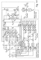
- shows a suitable circuit implementation of the proposed new 2-level unidirectional hybrid delta-switch rectifier according to
Fig. 4 ; - Fig. 10-11
- show novel unidirectional hybrid T-type systems according to further embodiments of the invention;
- Fig. 12
- shows the current reference generation for the DC-DC boost rectifier;
- Fig. 13
- shows simulation results for the unidirectional hybrid delta-switch rectifier for three different operation modes: (a) ideal PD>0.23Po; (b) unity power factor limit operation PD =0.23Po; and (c) distorted operation PD <0.23Po;
- Fig. 14
- shows a control scheme as an alternative for the control scheme shown in
Fig. 9 ; and - Fig. 15
- depicts simulation results for the unidirectional hybrid delta-switch rectifier for different operation modes.
- In the present application the hybrid rectifier concept is distinguished from an ordinary parallel association of rectifiers. For instance, in an AC-to-DC system assembled by a parallel connection of two unity power factor rectifiers, the input current in each unit is ideally sinusoidal. Additionally, each rectifier part is normally set to operate at the same switching frequency and to equally share the total load power.
- On the other hand, the rectifier units of the hybrid arrangements can operate with different power ratings at different frequencies. In these systems the line currents with sinusoidal shape are obtained by the combination of the currents drained for each rectifier unit, which doesn't necessarily display high power factor.
- Finally, hybrid rectifiers cannot be classified as active filters due to the fact that the self-commuted rectifier, in this case, processes high amounts of active power, while active filters are intended to process only reactive power [see C. H. IIIa Font and I. Barbi, "A new high power factor bidirectional hybrid three-phase rectifier," in Proc. of APEC 2006, pp. 1300-1306, 2006].
- In the present application, many new highly efficient 3-phase hybrid rectifiers with controlled DC-link voltage, capable of providing close to sinusoidal shaped line currents are proposed.
- For example, the hybrid rectifiers depicted in
Fig. 4 and 5 are novel rectifier concepts, which could be implemented with many basic switch types or switch configurations 21-24 shown inFig. 6-8. Fig. 6 shows a unipolar switch S1 comprising a single active switch Si,Fig. 7 shows various bidirectional (current) and bipolar (voltage) switches employing a single active switch Si (switchconfiguration 21 inFig. 7(a) ), or two active switches Si, and Si- (switch configuration Fig. 7(b) and (c) ), and a 3-phase power module (switchconfiguration 24 inFig. 8 ). - Additionally, a novel control method for hybrid rectifiers, able to handle a phase loss without changing the controller structure, is proposed. This new control scheme enhances the power sharing rating of the paralleled rectifier units; thus the systems can easily achieve higher efficiency than the control strategy introduced in the prior art [see for example R. L. Alves et al.].
-
Figs. 4 and 5 show two newhybrid rectifiers rectifier 11, a self-commutedrectifier boost converter 12. - In
Fig. 4 the self-commutedsystem 15 is based on a 2-level unidirectional delta-switch converter technology with a delta switch arrangement 20 [see Reference 6]. For thehybrid converter 14b depicted inFig. 5 , a 3-level unidirectional T-type rectifier is employed within the self-commutedsystem 16, wherein switches S2 connect a 3-phase rectifier bridge with acenter tap 25 at theDC output 18 at a series connection of two capacitances C1 and C2. - In fact, it is desired that the PWM rectifier processes the lowest power as possible in order to make the system more efficient. Therefore, the control proposed in
Fig. 9 is suitable for this matter. -
Fig. 9 shows a suitable circuit implementation of the proposed new 2-level unidirectional hybrid delta-switch rectifier (seeFig. 4 ), where the sinusoidal shaped line currents, iR,S,T, are formed by the sum of the currents of the combined rectifiers, iLR,LS,LT and iDR,DS,DT. Correspondingly, the output current, io, is derived from the sum of the output current of each paralleled rectifier unit. Novel unidirectional hybrid T-type systems Fig. 5 can be seen inFigs. 10 and11 . Here the respective self-commutedrectifiers Fig. 7(c) (Fig. 10 ) or 22 inFig. 7(b) (Fig. 11 ). The control scheme shown inFig. 9 can be easily adapted for these two hybrid T-type converters. - In order to guarantee the commutation of the
diode bridge rectifier 11 at low frequency, the controlled DC-DC boost rectifier 12 must operate in Continuous Conduction Mode (CCM). In contrast, the input currents of the delta-switch rectifier (Fig. 4 ), iDR,DS,DT, are controlled to allow high power factor operation. The current reference generation for the DC-DC boost rectifier 12 is shown inFig. 12 . - For hybrid rectifiers employing a bidirectional (current) self-commuted converter, the high power factor operation can be theoretically achieved for any combination of power shared between the compounding rectifiers. For example, if the line-commuted
rectifier 11 is set to process 100% of the output power, Po, the bidirectional system, working as an active filter, will be able to compensate the current harmonics, attaining unity power factor operation. - Unidirectional hybrid rectifiers have conditional high power factor operation, which is reliant on the rated active power processed by the self-commuted converter, PD. Due to the unidirectional power flow characteristic, the high line power quality operation can only be achieved if the instantaneous current absolute values of the line-commuted rectifier, iLR,LS,LT, are smaller than the absolute values of the line current references, iR,S,T.
- The simulation result showing this operation mode is presented in
Fig. 13(a) . The minimum rated output power processed by the active rectifier, PD, which allows imposed sinusoidal line currents, is given by PD≈0.23Po. This operation condition is illustrated inFig. 13(b) . Finally, for PD<0.23Po, the line currents become distorted as shown inFig. 13(c) . - The structure of the proposed control scheme is illustrated in
Fig. 9 . The voltage control loop establishes the DC voltage regulation and the output power sharing between the combined rectifiers of the hybrid system, which is defined mainly by the ratio of the gains k1 and k2 . In fact, the best compromise between high power factor and high efficiency operations is achieved when PD≈0.23Po. For the proposed control, this is established by simply setting k1 =1 and k2 =1. - The line current references, i*R,S,T, are generated by multiplying the sensed mains voltages, uR,S,T, by a reference conductance, g1, which is defined by the superimposed output voltage controller, Hu (s), rated by the established power loading sharing factor k1 . Together with a mains voltage feed-forward signal, the current controllers, H R,S, T(s), generate the required converter phase voltages. Subsequently, these signals are converted into line-to-line voltages. Finally, two independent PWM signals are generated guided by the clamping signals, derived from the grid voltages. The resulting clamping actions, considering all 60° space vector sectors, are shown in Table 1 (below). Note that "1" indicates that the corresponding active switch is turned on, "0" indicates the turn-off state, and "pwm" indicates that the transistor is modulated by the current controller.
Table 1 Sector S12 S21 S23 S32 S13 S31 330°-30° pwm 121 0 0 pwm 131 30°-90° 0 0 pwm 231 pwm 131 90°-150° 1 pwm21 pwm23 1 0 0 150°-210° 1 pwm21 0 0 1 pwm31 210°-270° 0 0 1 pwm 321 pwm31 270°-330° pwm 121 1 pwm32 0 0 - For the single-
switch boost converter 12 the current iBT is sensed and compared to the reference current signal, i*BT, generated by multiplying the reference signal uref (seeFig. 12 ), which is derived from the sensed grid voltages, by the conductance g2. The error signal is applied to the current compensator HB(s) and the PWM modulator, incorporating a feed-forward control loop, generates the gate signal of the boost switch. - Notice that by employing P-regulators for the controllers H R,S, T(s), the proposed control scheme becomes able to handle a phase loss operation without any change in the control structure being necessary. A respective converter specification is presented in Table 2 (see below). The results of simulations demonstrate that the line currents, IR,S,T, can effectively follow the sinusoidal input voltages, uR,S,T, even during mains phase loss. The THD of the line currents for 10 kW operation is approximately 3.5%.
Table 2 Input voltage, uR,S,T : 230 Vrms Input frequency, fin : 50 Hz Switching frequency, fs : 50 kHz DC-link voltage, UDC : 800 V Output power, P0 : 10 kW Self-commuted rectifier active power, PD : 4.5 kW Output capacitor, C0 : 1.47 mF DC inductor, Lb : 1 mH Delta-switch rectifier inductors, L1,2,3 : 1 mH - Experimental results obtained with a unidirectional hybrid delta-switch rectifier prototype demonstrate the performance and feasibility of this solution. The self-commuted system was air-cooled and had a power to weight ratio of 1.32 kW/kg. The power density of this rectifier was 2.35kW/dm3. A digital signal processing board with a TI DSP and a Lattice FPGA was used to implement the control strategy shown in
Fig. 9 . Three inductors with inductance values of 326µH were employed. In total, eighteen 82µF/450V electrolytic capacitors were arranged in parallel. - One alternative for the control scheme shown in
Fig. 9 , which also allows 2-phase operation with high power factor, is illustrated inFig. 14 . The main difference is on the current generation scheme of the single-switch boost converter. Here, the reference current signal, i*BT, is generated by multiplying the sensed rectified voltage, upn, by the conductance g2. - The minimum rated output power processed by the active rectifier, PD, which allows imposed sinusoidal line currents, is given by PD≈0.43Po. The ideal condition PD>0.43Po is illustrated in
Fig. 15(a) . The unit power factor limit operation PD≈0.43Po is illustrated inFig. 15(b) . Finally, for PD<0.43Po, the line currents become distorted as shown inFig. 15(c) . - For the alternative control scheme according to
Fig. 14 , simulation results of the unidirectional hybrid delta-switch rectifier operating close to the unity power factor limit, α≈0.45, demonstrate that the line currents, iR,S,T, can effectively follow the sinusoidal input voltages, uR,S,T, even during mains phase loss. - Unidirectional hybrid rectifiers have conditional high power factor operation, which is reliant on the rated active power processed by the self-commuted converter, PD. However, due to the unidirectional power flow characteristic, the high line power quality operation can only be achieved if the instantaneous current absolute values of the line-commuted rectifier, iLR,LS,LT, are smaller than the absolute values of the line current references, iR,S,T. With the control scheme presented in
Fig. 9 and k1 =1 and k2 =1 this condition is always satisfied, because the current references for each paralleled rectifier is found exactly equal to the desired line currents, iR,S,T, which avoid the overlap of the currents of the line-commuted rectifier. -
- 10a,b
- hybrid rectifier
- 11
- line-commuted rectifier
- 12
- boost converter
- 13
- self-commuted rectifier
- 14a-d
- hybrid rectifier
- 15,16
- self-commuted rectifier
- 16a,b
- self-commuted rectifier
- 17
- AC input
- 18
- DC output
- 19
- rectifier bridge (3-phase)
- 20
- delta switch arrangement
- 21-24
- switch configuration
- 25
- center tap
- C,C1,2
- capacitance
- L1,2
- inductance
- S1,2
- switch
- Si,Si+,Si-
- active switch
Claims (9)
- Hybrid rectifier (14a), comprising a line-commuted rectifier (11) and a self-commuted rectifier (15) working in parallel between a 3-phase AC input (17) and a DC output (18), characterized in that said self-commuted rectifier (15) is a 2-level unidirectional delta-switch rectifier.
- Hybrid rectifier according to claim 1, characterized in that said self-commuted rectifier (15) comprises a 3-phase rectifier bridge (19) being interconnected by means of a delta switch arrangement (20).
- Hybrid rectifier according to claim 1 or 2, characterized in that it further comprises a boost converter (12; L1,2; D1,2; S1).
- Hybrid rectifier (14b-d), comprising a line-commuted rectifier (11) and a self-commuted rectifier (16, 16a,b) working in parallel between a 3-phase AC input (17) and a DC output (18), characterized in that said self-commuted rectifier (16, 16a,b) is a 3-level unidirectional T-type rectifier.
- Hybrid rectifier according to claim 4, characterized in that the DC output (18) has a center tap (25), that said self-commuted rectifier (16, 16a,b) comprises a 3-phase rectifier bridge (19) being connected to said center tap (25) by means of bidirectional (current) and bipolar (voltage) switches (S2).
- Hybrid rectifier according to claim 3, characterized in that said bidirectional (current) and bipolar (voltage) switches (S2) each comprise a switch configuration (22, 23) with two active switches (Si+,Si-).
- Hybrid rectifier according to one of the claims 4-6, characterized in that it further comprises a boost converter (12; L1,2; D1,2; S1).
- Method for operating a hybrid rectifier (14a-d) according to one of the claims 1-7, wherein the sinusoidal shaped line currents (iR,S,T) are formed by the sum of the currents (iLR,LS,LT, iDR,DS,DT) of the combined rectifiers (11; 15, 16, 16a,b) and the output current (io) is derived from the sum of the output current of each paralleled rectifier (11; 15, 16, 16a,b).
- Method according to claim 8, characterized in that a voltage control loop establishes a DC voltage regulation and an output power sharing between the combined rectifiers (11; 15, 16, 16a,b) of the hybrid system.
Priority Applications (2)
| Application Number | Priority Date | Filing Date | Title |
|---|---|---|---|
| EP12176840.2A EP2590310A1 (en) | 2011-11-04 | 2012-07-18 | Hybrid rectifier and method of operating a hybrid rectifier |
| PCT/EP2012/071673 WO2013064608A2 (en) | 2011-11-04 | 2012-11-02 | Hybrid rectifier and method for operating such hybrid rectifier |
Applications Claiming Priority (2)
| Application Number | Priority Date | Filing Date | Title |
|---|---|---|---|
| EP11187884 | 2011-11-04 | ||
| EP12176840.2A EP2590310A1 (en) | 2011-11-04 | 2012-07-18 | Hybrid rectifier and method of operating a hybrid rectifier |
Publications (1)
| Publication Number | Publication Date |
|---|---|
| EP2590310A1 true EP2590310A1 (en) | 2013-05-08 |
Family
ID=46545273
Family Applications (1)
| Application Number | Title | Priority Date | Filing Date |
|---|---|---|---|
| EP12176840.2A Withdrawn EP2590310A1 (en) | 2011-11-04 | 2012-07-18 | Hybrid rectifier and method of operating a hybrid rectifier |
Country Status (2)
| Country | Link |
|---|---|
| EP (1) | EP2590310A1 (en) |
| WO (1) | WO2013064608A2 (en) |
Cited By (1)
| Publication number | Priority date | Publication date | Assignee | Title |
|---|---|---|---|---|
| CN111446873A (en) * | 2020-04-30 | 2020-07-24 | 北京信息科技大学 | Nonlinear passive current control method |
Families Citing this family (4)
| Publication number | Priority date | Publication date | Assignee | Title |
|---|---|---|---|---|
| CN107809131A (en) * | 2016-09-06 | 2018-03-16 | 伊顿制造(格拉斯哥)有限合伙莫尔日分支机构 | Uninterrupted power source |
| CN107346944A (en) * | 2017-08-29 | 2017-11-14 | 华北科技学院 | A kind of efficiently two-way mixing three-phase voltage type rectifier |
| CN108155820B (en) * | 2018-01-04 | 2020-01-17 | 北京信息科技大学 | A method for optimizing the operating energy of a hybrid rectifier |
| US10326357B1 (en) * | 2018-07-31 | 2019-06-18 | Raytheon Company | Adaptive power converter topologies supporting active power factor correction (PFC) |
-
2012
- 2012-07-18 EP EP12176840.2A patent/EP2590310A1/en not_active Withdrawn
- 2012-11-02 WO PCT/EP2012/071673 patent/WO2013064608A2/en not_active Ceased
Non-Patent Citations (5)
| Title |
|---|
| ALVES R L ET AL: "A Novel Unidirectional Hybrid Three-Phase Rectifier System Employing Boost Topology", POWER ELECTRONICS SPECIALISTS CONFERENCE, 2005. PESC '05. IEEE 36TH, IEEE, PISCATAWAY, NJ, USA, 12 June 2005 (2005-06-12), pages 487 - 493, XP010883251, ISBN: 978-0-7803-9033-1, DOI: 10.1109/PESC.2005.1581669 * |
| C. H. ILLA FONT; BARBI: "A new high power factor bidirectional hybrid three-phase rectifier", PROC. OF APEC 2006, 2006, pages 1300 - 1306, XP010910113, DOI: doi:10.1109/APEC.2006.1620707 |
| R. L. ALVES; BARBI: "Analysis and implementation of a hybrid high-power-factor three-phase unidirectional rectifier", IEEE TRANS. POWER ELECTRON., vol. 24, no. 3, March 2009 (2009-03-01), pages 632 - 640, XP011251680 |
| R. L. ALVES; C. H. ILLA FONT; BARBI: "Novel unidirectional hybrid three-phase rectifier system employing boost topology", PROC. OF PESC 2005, 2005, pages 487 - 493, XP031000213, DOI: doi:10.1109/PESC.2005.1581669 |
| SALMON J C: "Circuit topologies for PWM boost rectifiers operated from 1-phase and 3-phase AC supplies and using either single or split DC rail voltage outputs", APPLIED POWER ELECTRONICS CONFERENCE AND EXPOSITION, 1995. APEC '95. C ONFERENCE PROCEEDINGS 1995., TENTH ANNUAL DALLAS, TX, USA 5-9 MARCH 1995, NEW YORK, NY, USA,IEEE, US, 5 March 1995 (1995-03-05), pages 473 - 479, XP010147626, ISBN: 978-0-7803-2482-4, DOI: 10.1109/APEC.1995.468990 * |
Cited By (2)
| Publication number | Priority date | Publication date | Assignee | Title |
|---|---|---|---|---|
| CN111446873A (en) * | 2020-04-30 | 2020-07-24 | 北京信息科技大学 | Nonlinear passive current control method |
| CN111446873B (en) * | 2020-04-30 | 2021-08-17 | 北京信息科技大学 | A Nonlinear Passive Current Control Method |
Also Published As
| Publication number | Publication date |
|---|---|
| WO2013064608A2 (en) | 2013-05-10 |
| WO2013064608A3 (en) | 2013-10-17 |
Similar Documents
| Publication | Publication Date | Title |
|---|---|---|
| Soeiro et al. | Analysis of high-efficiency three-phase two-and three-level unidirectional hybrid rectifiers | |
| US6950322B2 (en) | Regulated AC to DC converter for aerospace applications | |
| Siu et al. | Manitoba rectifier—Bridgeless buck–boost PFC | |
| Mao et al. | Review of high-performance three-phase power-factor correction circuits | |
| US9148065B2 (en) | Bidirectional DC-DC converter | |
| CN102377324B (en) | Converter bridge arm suitable for high-voltage applications and application system thereof | |
| Zhou et al. | Variable switching frequency techniques for power converters: Review and future trends | |
| US20090040800A1 (en) | Three phase rectifier and rectification method | |
| US7310254B2 (en) | AC-to-AC (frequency) converter with three switches per leg | |
| Kim et al. | High-efficiency bridgeless three-level power factor correction rectifier | |
| US20120025609A1 (en) | Very high efficiency uninterruptible power supply | |
| Itoh et al. | A novel five-level three-phase PWM rectifier with reduced switch count | |
| WO2013064608A2 (en) | Hybrid rectifier and method for operating such hybrid rectifier | |
| Chao et al. | Power decoupling methods for single-phase three-poles AC/DC converters | |
| Shawky et al. | Space vector modulation scheme for three-phase single-stage SEPIC-based grid-connected differential inverter | |
| Park et al. | A novel sparse matrix converter with a Z-source network | |
| US12587111B2 (en) | Quasi multi-level converter | |
| Zhang et al. | Peak current reduction and zero cross distortion improvement for discontinuous current mode single phase grid-tied inverter | |
| Soeiro et al. | New unidirectional hybrid delta-switch rectifier | |
| Ohnuma et al. | Novel control strategy for single-phase to three-phase power converter using an active buffer | |
| Ram et al. | Study and Simulation of Single-Phase to Three-Phase UPF System for Agricultural Applications | |
| WO2014004289A1 (en) | A cyclo-converter and methods of operation | |
| Nishida et al. | A simple three-phase boost-mode PFC rectifier | |
| Chakraborty et al. | Design of T-NPC Inverter Based Power Supply for High Voltage Transformer-Rectifier Unit of DC Particle Accelerators | |
| CN102118113B (en) | Rectifier |
Legal Events
| Date | Code | Title | Description |
|---|---|---|---|
| PUAI | Public reference made under article 153(3) epc to a published international application that has entered the european phase |
Free format text: ORIGINAL CODE: 0009012 |
|
| AK | Designated contracting states |
Kind code of ref document: A1 Designated state(s): AL AT BE BG CH CY CZ DE DK EE ES FI FR GB GR HR HU IE IS IT LI LT LU LV MC MK MT NL NO PL PT RO RS SE SI SK SM TR |
|
| AX | Request for extension of the european patent |
Extension state: BA ME |
|
| 17P | Request for examination filed |
Effective date: 20131023 |
|
| RBV | Designated contracting states (corrected) |
Designated state(s): AL AT BE BG CH CY CZ DE DK EE ES FI FR GB GR HR HU IE IS IT LI LT LU LV MC MK MT NL NO PL PT RO RS SE SI SK SM TR |
|
| STAA | Information on the status of an ep patent application or granted ep patent |
Free format text: STATUS: THE APPLICATION IS DEEMED TO BE WITHDRAWN |
|
| 18D | Application deemed to be withdrawn |
Effective date: 20160202 |