EP2590285A2 - Flexible printed circuit board harness for a gas turbine engine - Google Patents
Flexible printed circuit board harness for a gas turbine engine Download PDFInfo
- Publication number
- EP2590285A2 EP2590285A2 EP12189694.8A EP12189694A EP2590285A2 EP 2590285 A2 EP2590285 A2 EP 2590285A2 EP 12189694 A EP12189694 A EP 12189694A EP 2590285 A2 EP2590285 A2 EP 2590285A2
- Authority
- EP
- European Patent Office
- Prior art keywords
- gas turbine
- turbine engine
- clip
- engine installation
- harness
- Prior art date
- Legal status (The legal status is an assumption and is not a legal conclusion. Google has not performed a legal analysis and makes no representation as to the accuracy of the status listed.)
- Granted
Links
Images


Classifications
-
- H—ELECTRICITY
- H02—GENERATION; CONVERSION OR DISTRIBUTION OF ELECTRIC POWER
- H02G—INSTALLATION OF ELECTRIC CABLES OR LINES, OR OF COMBINED OPTICAL AND ELECTRIC CABLES OR LINES
- H02G3/00—Installations of electric cables or lines or protective tubing therefor in or on buildings, equivalent structures or vehicles
- H02G3/30—Installations of cables or lines on walls, floors or ceilings
- H02G3/32—Installations of cables or lines on walls, floors or ceilings using mounting clamps
-
- F—MECHANICAL ENGINEERING; LIGHTING; HEATING; WEAPONS; BLASTING
- F02—COMBUSTION ENGINES; HOT-GAS OR COMBUSTION-PRODUCT ENGINE PLANTS
- F02C—GAS-TURBINE PLANTS; AIR INTAKES FOR JET-PROPULSION PLANTS; CONTROLLING FUEL SUPPLY IN AIR-BREATHING JET-PROPULSION PLANTS
- F02C7/00—Features, components parts, details or accessories, not provided for in, or of interest apart form groups F02C1/00 - F02C6/00; Air intakes for jet-propulsion plants
- F02C7/32—Arrangement, mounting, or driving, of auxiliaries
-
- F—MECHANICAL ENGINEERING; LIGHTING; HEATING; WEAPONS; BLASTING
- F05—INDEXING SCHEMES RELATING TO ENGINES OR PUMPS IN VARIOUS SUBCLASSES OF CLASSES F01-F04
- F05D—INDEXING SCHEME FOR ASPECTS RELATING TO NON-POSITIVE-DISPLACEMENT MACHINES OR ENGINES, GAS-TURBINES OR JET-PROPULSION PLANTS
- F05D2250/00—Geometry
- F05D2250/70—Shape
- F05D2250/75—Shape given by its similarity to a letter, e.g. T-shaped
-
- F—MECHANICAL ENGINEERING; LIGHTING; HEATING; WEAPONS; BLASTING
- F05—INDEXING SCHEMES RELATING TO ENGINES OR PUMPS IN VARIOUS SUBCLASSES OF CLASSES F01-F04
- F05D—INDEXING SCHEME FOR ASPECTS RELATING TO NON-POSITIVE-DISPLACEMENT MACHINES OR ENGINES, GAS-TURBINES OR JET-PROPULSION PLANTS
- F05D2260/00—Function
- F05D2260/30—Retaining components in desired mutual position
-
- Y—GENERAL TAGGING OF NEW TECHNOLOGICAL DEVELOPMENTS; GENERAL TAGGING OF CROSS-SECTIONAL TECHNOLOGIES SPANNING OVER SEVERAL SECTIONS OF THE IPC; TECHNICAL SUBJECTS COVERED BY FORMER USPC CROSS-REFERENCE ART COLLECTIONS [XRACs] AND DIGESTS
- Y02—TECHNOLOGIES OR APPLICATIONS FOR MITIGATION OR ADAPTATION AGAINST CLIMATE CHANGE
- Y02T—CLIMATE CHANGE MITIGATION TECHNOLOGIES RELATED TO TRANSPORTATION
- Y02T50/00—Aeronautics or air transport
- Y02T50/60—Efficient propulsion technologies, e.g. for aircraft
-
- Y—GENERAL TAGGING OF NEW TECHNOLOGICAL DEVELOPMENTS; GENERAL TAGGING OF CROSS-SECTIONAL TECHNOLOGIES SPANNING OVER SEVERAL SECTIONS OF THE IPC; TECHNICAL SUBJECTS COVERED BY FORMER USPC CROSS-REFERENCE ART COLLECTIONS [XRACs] AND DIGESTS
- Y10—TECHNICAL SUBJECTS COVERED BY FORMER USPC
- Y10T—TECHNICAL SUBJECTS COVERED BY FORMER US CLASSIFICATION
- Y10T29/00—Metal working
- Y10T29/49—Method of mechanical manufacture
- Y10T29/49826—Assembling or joining
- Y10T29/49947—Assembling or joining by applying separate fastener
- Y10T29/49959—Nonresilient fastener
Definitions
- This invention relates to a network for distributing signals and power around a gas turbine engine using a flexible harness.
- this invention relates to clips for holding a flexible harness for a gas turbine engine.
- a typical gas turbine engine has a substantial number of electrical components which serve, for example, to sense operating parameters of the engine and/or to control actuators which operate devices in the engine. Such devices may, for example, control fuel flow, variable vanes and air bleed valves.
- the actuators may themselves be electrically powered, although some may be pneumatically or hydraulically powered, but controlled by electrical signals.
- conductors Electrical power, and signals to and from the individual electrical components, are commonly transmitted along conductors.
- conductors may be in the form of wires and cables which are assembled together in a harness.
- each wire may be surrounded by an insulating sleeve, which may be braided or have a braided cover.
- the connections between the individual components and the conventional harness are made, for example, by multi-pin plug and socket connectors.
- communication between the harness and power, control and signalling circuitry is achieved through a multi-pin connector.
- Figure 1 of the accompanying drawings shows a typical gas turbine engine including two conventional wiring harnesses 102, 104, each provided with a respective connector component 106, 108 for connection to circuitry accommodated within the airframe of an aircraft in which the engine is installed.
- the harnesses 102, 104 are assembled from individual wires and cables which are held together over at least part of their lengths by suitable sleeving and/or braiding. Individual wires and cables, for example those indicated at 110, emerge from the sleeving or braiding to terminate at plug or socket connector components 112 for cooperation with complementary socket or plug connector components 114 on, or connected to, the respective electrical components.
- Each conventional harness 102, 104 therefore comprises a multitude of insulated wires and cables. This makes the conventional harness bulky, heavy and difficult to manipulate. It is desirable to reduce the size and weight of components on gas turbine engines, particularly, for example, gas turbine engines for use on vehicles, such as aircraft.
- FIG. 2 shows a perspective view of the FPCB harness portion
- Figures 3, 4, and 5 show side, top, and cross-sectional views respectively.
- Such an FPCB harness 20 may comprise a flexible (for example elastically deformable) substrate 40 with conductive tracks 30 laid/formed therein.
- the FPCB harness 20 may thus be deformable.
- the FPCB harness 20 extends along a length in the x-direction, a width in the y-direction, and a thickness (or depth or height) in the z-direction.
- the x direction may be defined as the axial direction of the FPCB harness.
- the x-direction (and thus the z-direction) may change along the length of the FPCB harness 20 as the FPCB harness is deformed. This is illustrated in Figure 3 .
- the x-y surface(s) may be said to be the major surface(s) of the FPCB harness.
- the FPCB harness is deformable in the z direction, i.e. in a direction perpendicular to the major surface.
- FPCB harnesses may be additionally of alternatively deformable about any other direction, and/or may be twisted about any one or more of the x, y, or z directions.
- the flexible substrate 40 may be a dielectric.
- the substrate material may be, by way of example only, polyamide. As will be readily apparent, other suitable substrate material could alternatively be used.
- the conductive tracks 30, which may be surrounded by the substrate, may be formed using any suitable conductive material, such as, by way of example only, copper, although other materials could alternatively be used.
- the conductive tracks 30 may be used to conduct/transfer electrical signals and/or electrical power, for example around a gas turbine engine and/or to/from components of a gas turbine engine and/or an airframe attached to a gas turbine engine.
- the size (for example the cross-sectional area) and/or the shape of the conductive tracks 30 may depend on the signal to be transmitted through the particular conductive track 30. Thus, the shape and/or size of the individual conductive tracks 30 may or may not be uniform in a FPCB harness 20.
- the example shown in Figures 2 to 5 has 6 conductive tracks 30 running through the substrate 40.
- the number of conductive tracks 30 running through a substrate 40 could be fewer than 6, or greater than 6.
- the number of conductive tracks 30 could be far greater than 6, for example tens or hundreds of tracks, as required.
- many electrical signals and/or power transmission lines may be incorporated into a single FPCB harness.
- a single FPCB harness 20 may comprise one layer of tracks, or more than one layer of tracks, for example, 2, 3, 4, 5, 6, 7, 8, 9, 10 or more than 10 layers of tracks.
- An FPCB harness may comprise significantly more than 10 layers of tracks, for example at least an order of magnitude more layers of tracks.
- a layer of tracks may be defined as being a series of tracks that extend in the same x-y surface.
- the example shown in Figures 2 to 5 comprises 2 layers of tracks 30, with each layer comprising 3 tracks.
- an FPCB harness to transmit electrical signals and/or power is therefore advantageous over a conventional harness, for example because of its reduced size, weight and/or complexity.
- a clip In order to attach a harness to a component (for example to a gas turbine engine or related airframe), a clip is required.
- An example of a clip that may be used to attach a conventional harness to a gas turbine engine is shown in Figure 7 .
- the clip 50 shown in Figure 7 is configured to hold a cable, or a bundle of cables which form at least a part of a conventional wire cable harness.
- the clip 50 has a generally cylindrical outer casing 52 with a diameter 58 and a structural internal element 54 configured to provide strength to the clip 50.
- the clip 50 shown in Figure 7 also has teeth 56 configured to grasp the generally cylindrical conventional cable harness, although the teeth 56 may not be present in some conventional clips.
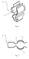
- Figures 8 and 9 show an alternative clip 60 for holding a conventional cable harness.
- the clip 60 shown in Figures 8 and 9 comprises two arms 64, 66 that define a space 62 therebetween for holding a conventional cable harness or bundle of cable harnesses.
- the space 62 defined between the two arms 64, 66 may be generally cylindrical.
- the two arms 64, 66 are sprung so as to be able to accommodate various diameters of conventional cable harnesses.
- FPCB harnesses have properties that present difficulties when considering how to attach them to components, for example of a gas turbine engine.
- the FPCB harnesses may have mechanical properties that mean that known clips, such as those described above, are not suitable for attaching them to components.
- the flexible substrate material may be relatively easily damaged (for example punctured or sliced) by conventional clips.
- FPCB harnesses offer considerable advantages over conventional harness in terms of, amongst other things, size and weight. It is desirable to maximize this size/weight benefit by providing an attachment device for allowing the FPCB harnesses to be connected to components in a compact, efficient manner. Conventional clips are therefore not desirable, or even suitable.
- a gas turbine engine installation comprising at least two flexible printed circuit board harnesses arranged to transfer electrical signals around the engine installation, and at least one clip holding at least two flexible printed circuit board harnesses.
- Each clip comprises a first jaw and a second jaw that hold respective first and second flexible printed circuit board harnesses.
- the first and second jaws each comprise a set of directly opposing, non-overlapping, compliant teeth arranged to grip the respective harness.
- the electrical signals can be of any type that may be transmitted along electrical conductors, for example electrical power transmission, and/or signals (for example control signals) to, from or between components (for example electrical components) of the gas turbine engine installation.
- the FPCB harnesses for transmitting the electrical signals may be as described herein, for example with reference to Figures 2 to 5 .
- An advantage of this arrangement of teeth in the jaws is that once the first flexible printed circuit board harness has been pushed into the first jaw and gripped by the respective teeth, the teeth of the second jaw do not (indeed cannot) intermesh. This means that the second flexible printed circuit board harness can be inserted into the second jaw even if the first flexible printed circuit board harness has already been inserted into the first jaw, because the teeth of the second jaw remain non-intermeshed at all times. If the teeth of the second jaw were to intermesh, it would be extremely difficult, or even impossible, to insert the second flexible printed circuit board harness into the second jaw.
- a further advantage of arranging the teeth to be directly opposing, non-overlapping and compliant is that it enables the respective FPCB harness to be appropriately gripped, whilst reducing (or substantially eliminating) the possibility of damage to the FPCB harness.
- the FPCB harness can remain substantially flat within the jaw (for example without containing regions of high curvature), thereby reducing the possibility of damage, such a splitting or fretting, to the FPCB harness.
- the invention provides a method of assembling a gas turbine engine installation.
- the method comprises providing at least two flexible printed circuit board harnesses arranged to transfer electrical signals (which, as explained above, may be of any type) around the engine installation.
- the method comprises attaching a first flexible printed circuit board harness to the rest of the gas turbine engine installation by inserting a portion thereof into a first jaw provided in a clip.
- the method comprises attaching a second flexible printed circuit board harness to the rest of the gas turbine engine installation, after attaching the first flexible printed circuit board harness, by inserting a portion thereof into a second jaw provided in the clip.
- Each jaw comprises a set of directly opposing, non-overlapping, compliant teeth, such that before and during the step of attaching the second flexible printed circuit board harness, the opposing teeth of the second jaw are not intermeshed.
- This method provides various advantages, including those outlined above and elsewhere herein in relation to the gas turbine engine installation.
- a gap may be provided between directly opposing teeth. Such a gap may be provided when the jaw is in an undeformed state, for example when no external forces are applied to it.
- the gap may be set to facilitate insertion of the FPCB into the jaw, whist providing sufficient grip to hold the FPCB in use.
- the gap may depend on the thickness of the FPCB harness intended to be inserted into the jaw.
- the gap may be set to allow FPCB harnesses with a range of thicknesses to be inserted.
- the gap may be in the range of from 0.1 mm to 10 mm, for example 0.5 mm to 5 mm, for example 1 mm to 4 mm, for example 2 mm to 3 mm, for example on the order of 2.5 mm.
- the tips of (some or all of) the teeth may be blunt. This may mean that the tips of the teeth may not be sharp, or not pointed. It may mean that the tips of the teeth do not have an apex. Thus, the tips of the teeth may be squared off, i.e. the parts of opposing teeth that face each other may be flat surfaces, which may be parallel. The tips of the teeth may take other suitable shapes, such as a rounded shape.
- Having blunt tips may help to reduce the pressure applied to the FPCB harness when it is gripped by the teeth. This may help to reduce, or substantially eliminate, the possibility of damage to the FPCB harness when it is gripped.
- At least one of the first and second jaws may be formed using a material comprising one or more of: ethylene-propylene rubber, a silicone based compound, and a nitrile material. These materials may provide good grip to a FPCB harness whilst being compliant so as to minimize the possibility of damage to the FPCB harness.
- the particular material may be chosen depending on the application, for example the environment (for example in terms of temperature variation) in which the clip is to be used and/or the type of FPCB harness it is to be used with.
- At least one clip may further comprise a support structure configured to resist changes in shape of the clip under operational loads.
- the support structure may be relatively more stiff than the jaws.
- the support structure may help to reduce, or substantially prevent flexing of the clip, for example flexing of the external shape of the clip. This may help to ensure that the jaws retain the desired shape under load, for example it may help to ensure that the jaws don't flex apart more than a desired amount when a FPCB harness is inserted. This may help to ensure that the FPCB harnesses are clamped with the desired force.
- the clip may comprise a main body that may incorporate the jaws.
- the main body may thus be integral with the jaws and, for example, manufactured from the same material and/or using the same process as the jaws.
- the support structure may extend around at least a part of the main body. This may be a convenient arrangement for providing structural support to the clip.
- the support structure may be formed using a material comprising metal and/or a composite/fibre resin.
- the support structure may thus be constructed using a material that is more stiff than the main body and/or the jaws of the clip. This may allow the clip to be structurally stiff, whilst retaining compliant teeth for gripping the FPCB harness.
- the support structure may further comprise an attachment portion used to attach the clip to the gas turbine engine, or a component thereof.
- the clip can be particularly compact, with a minimal number of parts required to attach it (and thus a FPCB harness) to a component. This may have further weight and/or size benefits.
- Each flexible printed circuit board harness may be described as a thin, elongate member.
- a thin, elongate member may have a major surface defined by a length and a width, and a thickness normal to the major surface.
- the teeth of the clip may thus contact, and grip, the major surface (the elongate member may be said to have two parallel major surfaces offset by the thickness of the FPCB, with one set of teeth contacting and gripping one major surface and the other set of teeth contacting and gripping the other major surface).
- the teeth of at least one clip may extend in a direction that corresponds to the length direction of the respective flexible printed circuit board harness when gripped. This may provide particularly strong resistance to the FPCB harness being pulled out of the jaw in the width direction.
- the teeth of at least one clip may extend in a direction that corresponds to the width direction of the respective flexible printed circuit board harness when gripped. This arrangement may facilitate insertion of the FPCB harness into the clip, and/or may provide particularly strong resistance to the FPCB harness being pulled through the jaw in the length direction.
- a lengthwise extending portion of the flexible printed circuit board harness may be held by two opposing clips, each opposing clip extending across no more than half of the width of the flexible printed circuit board harness.
- Such an arrangement may provide more secure retention of the FPCB harness. For example, such an arrangement may reduce (or substantially eliminate) the possibility of the FPCB harness being pulled out of a clip in a width direction.
- a ducted fan gas turbine engine generally indicated at 10 has a principal and rotational axis X-X.
- the engine 10 comprises, in axial flow series, an air intake 11, a propulsive fan 12, an intermediate pressure compressor 13, a high-pressure compressor 14, combustion equipment 15, a high-pressure turbine 16, and intermediate pressure turbine 17, a low-pressure turbine 18 and a core engine exhaust nozzle 19.
- the engine also has a bypass duct 22 and a bypass exhaust nozzle 23.
- the gas turbine engine 10 works in a conventional manner so that air entering the intake 11 is accelerated by the fan 12 to produce two air flows: a first air flow A into the intermediate pressure compressor 13 and a second air flow B which passes through the bypass duct 22 to provide propulsive thrust.
- the intermediate pressure compressor 13 compresses the air flow A directed into it before delivering that air to the high pressure compressor 14 where further compression takes place.
- the compressed air exhausted from the high-pressure compressor 14 is directed into the combustion equipment 15 where it is mixed with fuel and the mixture combusted.
- the resultant hot combustion products then expand through, and thereby drive the high, intermediate and low-pressure turbines 16, 17, 18 before being exhausted through the nozzle 19 to provide additional propulsive thrust.
- the high, intermediate and low-pressure turbines 16, 17, 18 respectively drive the high and intermediate pressure compressors 14, 13 and the fan 12 by suitable interconnecting shafts.
- the gas turbine engine 10 shown in Figure 6 may be at least a part of a gas turbine engine installation according to the present invention.
- the gas turbine engine 10 may comprise FPCB harnesses (such as those described above in relation to Figures 2 to 5 ) for transmitting/transferring electrical signals around the engine and/or to/from the engine 10 from other components, such as components of an airframe.
- FPCB harnesses such as those described above in relation to Figures 2 to 5
- the function and/or construction of the FPCB harnesses may be as described above and elsewhere herein.
- the clip 200 may have two jaws, or 4, 5, 6, 7, 8, 9, 10 or more than 10 jaws. It may also be possible to have clips with jaws of the type described and illustrated herein, but with only one jaw, although such clips with only one jaw would not have many of the advantages described herein in relation to the multi-jawed clips.
- Each jaw 202, 204, 206 has two sets of teeth, which may be referred to as an upper set of teeth 212 and a lower set of teeth 222.
- the teeth in the upper set 212 directly oppose corresponding teeth in the lower set 222.
- the tips of the teeth in both sets 212, 222 are aligned.
- the teeth in both sets 212, 222 are aligned in the width direction of the FPCB harness that they are designed to hold, i.e. in the direction labelled 'p' in Fig. 11 .
- the direction 'p' labelled in Figure 11 corresponds to the width direction 'y' of the FPCB harness shown in Figures 2 to 5 when inserted.
- more than one FPCB harness can be inserted into the clip 200 (and subsequently gripped by the teeth 212, 222 so as to be held) without undue difficulty.
- the opposing teeth of the other jaw(s) 202, 204 are prevented from becoming intermeshed, and thus further FPCB harnesses can be inserted into those jaws 202, 204 without undue hindrance.
- any suitable technique could be used.
- the FPCB harness 20 could be pushed into the respective jaw 202, 204, 206 in the width direction of the FPCB harness 20, i.e. in the direction labelled 'p' in Figure 11 , through the mouth 240 of the jaw 206.
- the FPCB harness 20 could be pushed into the respective jaw 202, 204, 206 in the width direction of the FPCB harness 20, i.e. in the direction labelled 'p' in Figure 11 , through the mouth 240 of the jaw 206.
- no further steps may be required in order for it to be gripped by the sets of teeth 212, 222.
- the first clip 200A may be secured to the desired component
- the FPCB harness may be inserted into the first clip 200A as described above, then the second clip 200B may be slid over the other side (in a width sense) of the FPCB harness, then the second clip 200B may be secured to the component.
- the FPCB harness is held by the clip 200, for example through being gripped by the opposing teeth 212, 222, which may be compliant and/or flexible and/or elastically deformable.
- the teeth 211, 213 of the Figure 10 and 11 embodiment have blunt tips 215.
- the tips 215 are squared off, and thus do not terminate in a sharp point or line.
- the teeth 211, 213 may thus be said to be truncated wedges.
- the teeth may be said to be elongate, with a longitudinal axis extending in the length direction of the FPCB harness that they are designed to receive.
- the clips 200, 300 shown in Figures 10 to 13 have a support structure 400.
- the support structure provides support to the main body 201, 301 of the clip so as to restrict or minimize flexing/bending of the clip 200, 300.
- the support structure 400 may thus be stiffer, for example constructed from a stiffer material, than the main body of the clip 201, 301.
- the support structure 400 shown in the Figures is attached (for example bonded) to external surfaces of the main body 201, 301. However, other arrangements of support structure 400 may be used.
- the support structure may penetrate into the material of the main body 201, 301 of the clips 200, 300, for example between the jaws.
- the support structure 400 shown in the Figures comprises two parts 410, 420, that may be attached together (for example by welding) to produce the final support structure 400. Again, other constructions could be used in clips for alternative embodiments.
- any suitable material may be used to manufacture the main body 201, 301 of the clips 200, 300, which may be the same as the material used to manufacture the jaws 202, 204, 206, 302, 304, 306.
- the material may comprise one or more of ethylene-propylene rubber, a silicone based compound, and a nitrile material.
- the support structure 400 may be constructed from a stiffer material than the main body 201, 301, for example from a metal and/or a resin/fibre composite.
- gas turbine engine installation may include a gas turbine engine and/or any peripheral components to which the gas turbine engine may be connected to or interact with and/or any connections/interfaces with surrounding components, which may include, for example, an airframe and/or components thereof.
- connections with an airframe which are encompassed by the term 'gas turbine engine installation' as used herein include, but are not limited to, pylons and mountings and their respective connections.
- the gas turbine engine itself may be any type of gas turbine engine, including, but not limited to, a turbofan (bypass) gas turbine engine, turbojet, turboprop, ramjet, scramjet or open rotor gas turbine engine, industrial
- a turbofan (bypass) gas turbine engine turbojet, turboprop, ramjet, scramjet or open rotor gas turbine engine
- industrial gas turbine engine
- many alternative configurations and/or arrangements of the clips 200, 300 other than those described herein may fall within the scope of the invention.
- alternative arrangements of jaws 202, teeth sets 212, 222, tooth geometry 211 (such as tip geometry 215), support structure 400, and/or FPCB harness 20 may fall within the scope of the invention and may be readily apparent to the skilled person from the disclosure provided herein.
- any feature described and/or claimed herein may be combined with any other compatible feature described in relation to the same or another embodiment.
Landscapes
- Engineering & Computer Science (AREA)
- Chemical & Material Sciences (AREA)
- Combustion & Propulsion (AREA)
- Mechanical Engineering (AREA)
- General Engineering & Computer Science (AREA)
- Architecture (AREA)
- Civil Engineering (AREA)
- Structural Engineering (AREA)
- Installation Of Indoor Wiring (AREA)
- Structure Of Printed Boards (AREA)
Abstract
Description
- This invention relates to a network for distributing signals and power around a gas turbine engine using a flexible harness. In particular, this invention relates to clips for holding a flexible harness for a gas turbine engine.
- A typical gas turbine engine has a substantial number of electrical components which serve, for example, to sense operating parameters of the engine and/or to control actuators which operate devices in the engine. Such devices may, for example, control fuel flow, variable vanes and air bleed valves. The actuators may themselves be electrically powered, although some may be pneumatically or hydraulically powered, but controlled by electrical signals.
- Electrical power, and signals to and from the individual electrical components, are commonly transmitted along conductors. Conventionally, such conductors may be in the form of wires and cables which are assembled together in a harness. In such a conventional harness, each wire may be surrounded by an insulating sleeve, which may be braided or have a braided cover. The connections between the individual components and the conventional harness are made, for example, by multi-pin plug and socket connectors. Similarly, communication between the harness and power, control and signalling circuitry is achieved through a multi-pin connector.
- By way of example,
Figure 1 of the accompanying drawings shows a typical gas turbine engine including twoconventional wiring harnesses respective connector component - The
harnesses socket connector components 112 for cooperation with complementary socket orplug connector components 114 on, or connected to, the respective electrical components. - Each
conventional harness - It is proposed to replace at least a portion of, for example all of, the conventional harness with a flexible printed circuit board harness (FPCB harness). An example of a portion of such a flexible printed
circuit board harness 20 is shown inFigures 2 to 5. Figure 2 shows a perspective view of the FPCB harness portion, andFigures 3, 4, and 5 show side, top, and cross-sectional views respectively. - Such an FPCB
harness 20 may comprise a flexible (for example elastically deformable)substrate 40 withconductive tracks 30 laid/formed therein. The FPCBharness 20 may thus be deformable. In the example shown inFigures 2 to 5 , theFPCB harness 20 extends along a length in the x-direction, a width in the y-direction, and a thickness (or depth or height) in the z-direction. The x direction may be defined as the axial direction of the FPCB harness. Thus, the x-direction (and thus the z-direction) may change along the length of theFPCB harness 20 as the FPCB harness is deformed. This is illustrated inFigure 3 . The x-y surface(s) may be said to be the major surface(s) of the FPCB harness. In the example shown inFigures 2 to 5 , the FPCB harness is deformable in the z direction, i.e. in a direction perpendicular to the major surface. FPCB harnesses may be additionally of alternatively deformable about any other direction, and/or may be twisted about any one or more of the x, y, or z directions. - The
flexible substrate 40 may be a dielectric. By way of example, the substrate material may be, by way of example only, polyamide. As will be readily apparent, other suitable substrate material could alternatively be used. - The
conductive tracks 30, which may be surrounded by the substrate, may be formed using any suitable conductive material, such as, by way of example only, copper, although other materials could alternatively be used. Theconductive tracks 30 may be used to conduct/transfer electrical signals and/or electrical power, for example around a gas turbine engine and/or to/from components of a gas turbine engine and/or an airframe attached to a gas turbine engine. The size (for example the cross-sectional area) and/or the shape of theconductive tracks 30 may depend on the signal to be transmitted through the particularconductive track 30. Thus, the shape and/or size of the individualconductive tracks 30 may or may not be uniform in aFPCB harness 20. - The example shown in
Figures 2 to 5 has 6conductive tracks 30 running through thesubstrate 40. However, the number ofconductive tracks 30 running through asubstrate 40 could be fewer than 6, or greater than 6. Indeed the number ofconductive tracks 30 could be far greater than 6, for example tens or hundreds of tracks, as required. As such, many electrical signals and/or power transmission lines may be incorporated into a single FPCB harness. - A
single FPCB harness 20 may comprise one layer of tracks, or more than one layer of tracks, for example, 2, 3, 4, 5, 6, 7, 8, 9, 10 or more than 10 layers of tracks. An FPCB harness may comprise significantly more than 10 layers of tracks, for example at least an order of magnitude more layers of tracks. In this regard, a layer of tracks may be defined as being a series of tracks that extend in the same x-y surface. Thus, the example shown inFigures 2 to 5 comprises 2 layers oftracks 30, with each layer comprising 3 tracks. - Using an FPCB harness to transmit electrical signals and/or power is therefore advantageous over a conventional harness, for example because of its reduced size, weight and/or complexity.
- In order to attach a harness to a component (for example to a gas turbine engine or related airframe), a clip is required. An example of a clip that may be used to attach a conventional harness to a gas turbine engine is shown in
Figure 7 . Theclip 50 shown inFigure 7 is configured to hold a cable, or a bundle of cables which form at least a part of a conventional wire cable harness. Theclip 50 has a generally cylindricalouter casing 52 with adiameter 58 and a structuralinternal element 54 configured to provide strength to theclip 50. Theclip 50 shown inFigure 7 also hasteeth 56 configured to grasp the generally cylindrical conventional cable harness, although theteeth 56 may not be present in some conventional clips. -
Figures 8 and 9 show analternative clip 60 for holding a conventional cable harness. Theclip 60 shown inFigures 8 and 9 comprises twoarms space 62 therebetween for holding a conventional cable harness or bundle of cable harnesses. Thespace 62 defined between the twoarms arms - FPCB harnesses have properties that present difficulties when considering how to attach them to components, for example of a gas turbine engine. For example, the FPCB harnesses may have mechanical properties that mean that known clips, such as those described above, are not suitable for attaching them to components. Purely by way of example only, the flexible substrate material may be relatively easily damaged (for example punctured or sliced) by conventional clips.
- As explained herein, FPCB harnesses offer considerable advantages over conventional harness in terms of, amongst other things, size and weight. It is desirable to maximize this size/weight benefit by providing an attachment device for allowing the FPCB harnesses to be connected to components in a compact, efficient manner. Conventional clips are therefore not desirable, or even suitable.
- According to the an aspect of the invention, there is provided a gas turbine engine installation comprising at least two flexible printed circuit board harnesses arranged to transfer electrical signals around the engine installation, and at least one clip holding at least two flexible printed circuit board harnesses. Each clip comprises a first jaw and a second jaw that hold respective first and second flexible printed circuit board harnesses. The first and second jaws each comprise a set of directly opposing, non-overlapping, compliant teeth arranged to grip the respective harness.
- The electrical signals can be of any type that may be transmitted along electrical conductors, for example electrical power transmission, and/or signals (for example control signals) to, from or between components (for example electrical components) of the gas turbine engine installation. The FPCB harnesses for transmitting the electrical signals may be as described herein, for example with reference to
Figures 2 to 5 . - Because the sets of teeth in each jaw are directly opposing, their tips may not intermesh if the sets of teeth are pushed together. Instead, if the sets of teeth are pushed together (i.e. opposing teeth are moved towards each other), the tips of the opposing teeth may come into contact with each other, but cannot move past each other. As such, this arrangement of teeth means that the opposing teeth in a jaw cannot overlap (i.e. the tips of the upper set of teeth cannot move past than the tips of the lower set of teeth and vice versa), and thus cannot intermesh when pushed together.
- An advantage of this arrangement of teeth in the jaws is that once the first flexible printed circuit board harness has been pushed into the first jaw and gripped by the respective teeth, the teeth of the second jaw do not (indeed cannot) intermesh. This means that the second flexible printed circuit board harness can be inserted into the second jaw even if the first flexible printed circuit board harness has already been inserted into the first jaw, because the teeth of the second jaw remain non-intermeshed at all times. If the teeth of the second jaw were to intermesh, it would be extremely difficult, or even impossible, to insert the second flexible printed circuit board harness into the second jaw.
- A further advantage of arranging the teeth to be directly opposing, non-overlapping and compliant is that it enables the respective FPCB harness to be appropriately gripped, whilst reducing (or substantially eliminating) the possibility of damage to the FPCB harness. For example, by avoiding the possibility of opposing teeth intermeshing, the FPCB harness can remain substantially flat within the jaw (for example without containing regions of high curvature), thereby reducing the possibility of damage, such a splitting or fretting, to the FPCB harness.
- The invention provides a method of assembling a gas turbine engine installation. The method comprises providing at least two flexible printed circuit board harnesses arranged to transfer electrical signals (which, as explained above, may be of any type) around the engine installation. The method comprises attaching a first flexible printed circuit board harness to the rest of the gas turbine engine installation by inserting a portion thereof into a first jaw provided in a clip. The method comprises attaching a second flexible printed circuit board harness to the rest of the gas turbine engine installation, after attaching the first flexible printed circuit board harness, by inserting a portion thereof into a second jaw provided in the clip. Each jaw comprises a set of directly opposing, non-overlapping, compliant teeth, such that before and during the step of attaching the second flexible printed circuit board harness, the opposing teeth of the second jaw are not intermeshed.
- This method provides various advantages, including those outlined above and elsewhere herein in relation to the gas turbine engine installation.
- A gap may be provided between directly opposing teeth. Such a gap may be provided when the jaw is in an undeformed state, for example when no external forces are applied to it. The gap may be set to facilitate insertion of the FPCB into the jaw, whist providing sufficient grip to hold the FPCB in use. The gap may depend on the thickness of the FPCB harness intended to be inserted into the jaw. The gap may be set to allow FPCB harnesses with a range of thicknesses to be inserted.
- The gap may be in the range of from 0.1 mm to 10 mm, for example 0.5 mm to 5 mm, for example 1 mm to 4 mm, for example 2 mm to 3 mm, for example on the order of 2.5 mm. In alternative arrangements, there may be no gap between opposing teeth in a jaw in the undeformed state. This may be particularly suitable for holding particularly thin FPCB harnesses.
- The tips of (some or all of) the teeth may be blunt. This may mean that the tips of the teeth may not be sharp, or not pointed. It may mean that the tips of the teeth do not have an apex. Thus, the tips of the teeth may be squared off, i.e. the parts of opposing teeth that face each other may be flat surfaces, which may be parallel. The tips of the teeth may take other suitable shapes, such as a rounded shape.
- Having blunt tips may help to reduce the pressure applied to the FPCB harness when it is gripped by the teeth. This may help to reduce, or substantially eliminate, the possibility of damage to the FPCB harness when it is gripped.
- At least one of the first and second jaws may be formed using a material comprising one or more of: ethylene-propylene rubber, a silicone based compound, and a nitrile material. These materials may provide good grip to a FPCB harness whilst being compliant so as to minimize the possibility of damage to the FPCB harness. The particular material may be chosen depending on the application, for example the environment (for example in terms of temperature variation) in which the clip is to be used and/or the type of FPCB harness it is to be used with.
- At least one clip (for example all clips) may further comprise a support structure configured to resist changes in shape of the clip under operational loads. The support structure may be relatively more stiff than the jaws. As such, the support structure may help to reduce, or substantially prevent flexing of the clip, for example flexing of the external shape of the clip. This may help to ensure that the jaws retain the desired shape under load, for example it may help to ensure that the jaws don't flex apart more than a desired amount when a FPCB harness is inserted. This may help to ensure that the FPCB harnesses are clamped with the desired force.
- The clip may comprise a main body that may incorporate the jaws. The main body may thus be integral with the jaws and, for example, manufactured from the same material and/or using the same process as the jaws. The support structure may extend around at least a part of the main body. This may be a convenient arrangement for providing structural support to the clip.
- The support structure may be formed using a material comprising metal and/or a composite/fibre resin. The support structure may thus be constructed using a material that is more stiff than the main body and/or the jaws of the clip. This may allow the clip to be structurally stiff, whilst retaining compliant teeth for gripping the FPCB harness.
- The support structure may further comprise an attachment portion used to attach the clip to the gas turbine engine, or a component thereof. Thus, the clip can be particularly compact, with a minimal number of parts required to attach it (and thus a FPCB harness) to a component. This may have further weight and/or size benefits.
- Each flexible printed circuit board harness may be described as a thin, elongate member. Such a thin, elongate member may have a major surface defined by a length and a width, and a thickness normal to the major surface. The teeth of the clip may thus contact, and grip, the major surface (the elongate member may be said to have two parallel major surfaces offset by the thickness of the FPCB, with one set of teeth contacting and gripping one major surface and the other set of teeth contacting and gripping the other major surface).
- The teeth of at least one clip may extend in a direction that corresponds to the length direction of the respective flexible printed circuit board harness when gripped. This may provide particularly strong resistance to the FPCB harness being pulled out of the jaw in the width direction.
- The teeth of at least one clip may extend in a direction that corresponds to the width direction of the respective flexible printed circuit board harness when gripped. This arrangement may facilitate insertion of the FPCB harness into the clip, and/or may provide particularly strong resistance to the FPCB harness being pulled through the jaw in the length direction.
- A lengthwise extending portion of the flexible printed circuit board harness may be held by two opposing clips, each opposing clip extending across no more than half of the width of the flexible printed circuit board harness. Such an arrangement may provide more secure retention of the FPCB harness. For example, such an arrangement may reduce (or substantially eliminate) the possibility of the FPCB harness being pulled out of a clip in a width direction.
- The invention will now be described, by way of example only, with reference to the accompanying Figures, in which:
-
Figure 1 shows a gas turbine engine with a conventional harness; -
Figure 2 shows perspective view of a portion of a flexible printed circuit board harness; -
Figure 3 shows a side view of the flexible printed circuit board harness ofFigure 2 ; -
Figure 4 shows a top view of the flexible printed circuit board harness ofFigure 2 ; -
Figure 5 shows a cross-sectional view of the flexible printed circuit board harness ofFigure 2 ; -
Figure 6 is a cross-section through a gas turbine engine; -
Figure 7 shows a side view of a clip for holding a conventional harness in place; -
Figure 8 shows a perspective view of an alternative clip for holding a conventional harness in place; -
Figure 9 shows a side view of the clip shown inFigure 8 ; -
Figure 10 shows a perspective view of clip in accordance with the present invention; -
Figure 11 shows a side view of two clips according toFigure 10 ; -
Figure 12 shows a front view of an alternative clip in accordance with the present invention; and -
Figure 13 shows a side view of two clips according toFigure 12 . - With reference to
Figure 6 , a ducted fan gas turbine engine generally indicated at 10 has a principal and rotational axis X-X. Theengine 10 comprises, in axial flow series, anair intake 11, apropulsive fan 12, anintermediate pressure compressor 13, a high-pressure compressor 14,combustion equipment 15, a high-pressure turbine 16, andintermediate pressure turbine 17, a low-pressure turbine 18 and a coreengine exhaust nozzle 19. The engine also has abypass duct 22 and abypass exhaust nozzle 23. - The
gas turbine engine 10 works in a conventional manner so that air entering theintake 11 is accelerated by thefan 12 to produce two air flows: a first air flow A into theintermediate pressure compressor 13 and a second air flow B which passes through thebypass duct 22 to provide propulsive thrust. Theintermediate pressure compressor 13 compresses the air flow A directed into it before delivering that air to thehigh pressure compressor 14 where further compression takes place. - The compressed air exhausted from the high-
pressure compressor 14 is directed into thecombustion equipment 15 where it is mixed with fuel and the mixture combusted. The resultant hot combustion products then expand through, and thereby drive the high, intermediate and low-pressure turbines nozzle 19 to provide additional propulsive thrust. The high, intermediate and low-pressure turbines intermediate pressure compressors fan 12 by suitable interconnecting shafts. - The
gas turbine engine 10 shown inFigure 6 may be at least a part of a gas turbine engine installation according to the present invention. Thegas turbine engine 10 may comprise FPCB harnesses (such as those described above in relation toFigures 2 to 5 ) for transmitting/transferring electrical signals around the engine and/or to/from theengine 10 from other components, such as components of an airframe. The function and/or construction of the FPCB harnesses may be as described above and elsewhere herein. - The FPCB harnesses may be attached to any part of the engine installation (of which the
engine 10 may be a part) using a clip such as theclip 200 shown inFigures 10 and 11 . In each ofFigures 10 and 11 , twoclips clips FPCB harness 20. Alternatively, just one of theclips 200 may be used to hold a FPCB harness. - Each
clip 200 has threejaws main body 201. Eachjaw respective FPCB harness 20. In particular, eachjaw respective FPCB harness 20. The number of jaws corresponds to the number of FPCB harnesses that theclip 200 can hold. In the example shown inFigure 11 , theclip 200 is capable of holding 3 FPCB harnesses, but is only shown holding 2 FPCB harnesses 20. Other embodiments may thus comprise different numbers of jaws. For example, theclip 200 may have two jaws, or 4, 5, 6, 7, 8, 9, 10 or more than 10 jaws. It may also be possible to have clips with jaws of the type described and illustrated herein, but with only one jaw, although such clips with only one jaw would not have many of the advantages described herein in relation to the multi-jawed clips. - Each
jaw teeth 212 and a lower set ofteeth 222. The teeth in theupper set 212 directly oppose corresponding teeth in thelower set 222. Thus, the tips of the teeth in bothsets Figure 11 example, the teeth in bothsets Fig. 11 . Note that the direction 'p' labelled inFigure 11 corresponds to the width direction 'y' of the FPCB harness shown inFigures 2 to 5 when inserted. - A gap 232 is provided between opposing teeth, i.e. between the upper set of
teeth 212 and the lower set ofteeth 222. This gap may be set according to the type of FPCB harness that thejaws Figures 2 to 5 ) of the FPCB harness being held. The gap 232 could be different for thejaws same clip 200, if, for example, theclip 200 is intended to carry/hold FPCB harnesses of different thicknesses. In the example shown inFigure 11 , however, the gap 232 is the same for alljaws - Some embodiments may have no gap 232 between opposing
teeth teeth Figure 11 (which corresponds to the thickness direction 'z' of the FPCB harness shown inFigures 2 to 5 when installed). Thus theteeth teeth teeth - Because the upper and lower sets of teeth directly oppose each other, and thus cannot overlap so as to become intermeshed, more than one FPCB harness can be inserted into the clip 200 (and subsequently gripped by the
teeth jaws - In order to insert an
FPCB harness 20 into ajaw FPCB harness 20 could be pushed into therespective jaw FPCB harness 20, i.e. in the direction labelled 'p' inFigure 11 , through themouth 240 of thejaw 206. Where only oneclip 200 is used to hold a givenFPCB harness 20, no further steps may be required in order for it to be gripped by the sets ofteeth clips FPCB harness 20, thefirst clip 200A may be secured to the desired component, the FPCB harness may be inserted into thefirst clip 200A as described above, then thesecond clip 200B may be slid over the other side (in a width sense) of the FPCB harness, then thesecond clip 200B may be secured to the component. Of course, these are only examples of many possible ways in which anFPCB harness 20 could be attached to a component using oneclip 200 or twoclips - Once inserted, the FPCB harness is held by the
clip 200, for example through being gripped by the opposingteeth teeth Figure 10 and 11 embodiment haveblunt tips 215. Thetips 215 are squared off, and thus do not terminate in a sharp point or line. Theteeth -
Figures 12 and 13 show a further embodiment ofclip 300 for use in the present invention. Theclip 300 also has threejaws jaws Figures 12 and 13 . Theclip 300 ofFigures 12 and 13 shares many aspects and/or features with the embodiment ofFigures 10 and 11 . For example, eachjaw teeth teeth Figures 10 and 11 . - In the
Figure 12 and 13 clip 300, however, theteeth teeth Figure 10 and 11 embodiment. Theteeth Figure 12 and 13 embodiment are elongate teeth with a longitudinal axis running in the width direction 'y' of theFPCB harness 20 that they are designed to receive. Thus, in theFigure 12 and 13 clip 300, the upper and lower sets ofteeth Figure 12 , so as to be directly opposed. - The
clips Figures 10 to 13 have asupport structure 400. The support structure provides support to themain body clip support structure 400 may thus be stiffer, for example constructed from a stiffer material, than the main body of theclip support structure 400 shown in the Figures is attached (for example bonded) to external surfaces of themain body support structure 400 may be used. For example, the support structure may penetrate into the material of themain body clips support structure 400 shown in the Figures comprises twoparts final support structure 400. Again, other constructions could be used in clips for alternative embodiments. - The
support structure 400 shown in the figures has an attachment portion 430 (which in the illustrated example comprises a hole for receiving a fixing element, such as a screw, bolt, or rivet) that is configured to allow theclip clips support structure 400 at all, or may have asupport structure 400 without anattachment portion 430. - Any suitable material may be used to manufacture the
main body clips jaws support structure 400, thesupport structure 400 may be constructed from a stiffer material than themain body - The
clip FPCB harness 20. Purely by way of non-limitative example, and with reference toFigure 10 , the width 'w' of theclip clip clip - Where reference is made herein to a gas turbine engine installation, it will be appreciated that this term may include a gas turbine engine and/or any peripheral components to which the gas turbine engine may be connected to or interact with and/or any connections/interfaces with surrounding components, which may include, for example, an airframe and/or components thereof. Such connections with an airframe, which are encompassed by the term 'gas turbine engine installation' as used herein include, but are not limited to, pylons and mountings and their respective connections. The gas turbine engine itself may be any type of gas turbine engine, including, but not limited to, a turbofan (bypass) gas turbine engine, turbojet, turboprop, ramjet, scramjet or open rotor gas turbine engine, industrial It will be appreciated that many alternative configurations and/or arrangements of the
clips jaws 202, teeth sets 212, 222, tooth geometry 211 (such as tip geometry 215),support structure 400, and/orFPCB harness 20 may fall within the scope of the invention and may be readily apparent to the skilled person from the disclosure provided herein. Furthermore, any feature described and/or claimed herein may be combined with any other compatible feature described in relation to the same or another embodiment.
Claims (14)
- A gas turbine engine installation comprising:at least two flexible printed circuit board harnesses (20) arranged to transfer electrical signals around the engine installation; andat least one clip (200) holding at least two flexible printed circuit board harnesses, each clip comprising:a first jaw (202) and a second jaw (204) holding respective first and second flexible printed circuit board harnesses, the first and second jaws each comprising a set of directly opposing, non-overlapping, compliant teeth (212, 222) arranged to grip the respective harness.
- A gas turbine engine installation according to claim 1, wherein a gap is provided between directly opposing teeth.
- A gas turbine engine installation according to claim 2, wherein the gap is in the range of from 0.1 mm to 5 mm.
- A gas turbine engine installation according to any one of claims 1 to 3,
wherein the teeth (211, 213) extend to a tip (215), and the tips of the teeth are blunt. - A gas turbine engine installation according to any one of the preceding claims, wherein the first and second jaws are formed using a material comprising one or more of: ethylene-propylene rubber, a silicone based compound, and a nitrile material.
- A gas turbine engine installation according to any one of the preceding claims, wherein at least one clip further comprises a support structure (400) configured to resist changes in the shape of the clip under operational loads, the support structure being relatively stiffer than the jaws.
- A gas turbine engine installation according to claim 6, wherein:the clip comprises a main body (201) that incorporates the jaws; andthe support structure extends around at least a part of the main body.
- A gas turbine engine installation according to claim 6 or claim 7, wherein the support structure is formed using a material comprising metal and/or a composite/fibre resin.
- A gas turbine engine installation according to any one of claims 6 to 8,
wherein the support structure further comprises an attachment portion (430) used to attach the clip to the gas turbine engine installation, or a component thereof. - A gas turbine engine installation according to any one of the preceding claims, wherein each flexible printed circuit board harness is a thin, elongate member having a major surface defined by a length and a width, and a thickness normal to the major surface.
- A gas turbine engine installation according to claim 10, wherein the teeth of at least one clip extend in a direction that corresponds to the length direction of the respective flexible printed circuit board harness when gripped.
- A gas turbine engine installation according to claim 10, wherein the teeth of at least one clip extend in a direction that corresponds to the width direction of the respective flexible printed circuit board harness when gripped.
- A gas turbine engine installation according to claim 10, wherein:a lengthwise extending portion of a flexible printed circuit board harness is held by two opposing clips (200A, 200B), each opposing clip extending across no more than half of the width of the flexible printed circuit board harness.
- A method of assembling a gas turbine engine installation comprising:providing at least two flexible printed circuit board harness (20) arranged to transfer electrical signals around the engine installation;attaching a first flexible printed circuit board harness to the rest of the gas turbine engine installation by inserting a portion thereof into a first jaw (202) provided in a clip (200); andattaching a second flexible printed circuit board harness to the rest of the gas turbine engine installation, after attaching the first flexible printed circuit board harness, by inserting a portion thereof into a second jaw (204) provided in the clip, wherein:each jaw comprises a set of directly opposing, non-overlapping, compliant teeth (212, 222), such that before and during the step of attaching the second flexible printed circuit board harness, the opposing teeth of the second jaw are not intermeshed.
Applications Claiming Priority (1)
| Application Number | Priority Date | Filing Date | Title |
|---|---|---|---|
| GB201119037A GB201119037D0 (en) | 2011-11-04 | 2011-11-04 | Flexible printed circuit board harness |
Publications (3)
| Publication Number | Publication Date |
|---|---|
| EP2590285A2 true EP2590285A2 (en) | 2013-05-08 |
| EP2590285A3 EP2590285A3 (en) | 2013-10-02 |
| EP2590285B1 EP2590285B1 (en) | 2014-07-23 |
Family
ID=45375784
Family Applications (1)
| Application Number | Title | Priority Date | Filing Date |
|---|---|---|---|
| EP20120189694 Active EP2590285B1 (en) | 2011-11-04 | 2012-10-24 | Flexible printed circuit board harness for a gas turbine engine |
Country Status (3)
| Country | Link |
|---|---|
| US (1) | US9019722B2 (en) |
| EP (1) | EP2590285B1 (en) |
| GB (1) | GB201119037D0 (en) |
Cited By (2)
| Publication number | Priority date | Publication date | Assignee | Title |
|---|---|---|---|---|
| NL2015404B1 (en) * | 2015-09-07 | 2017-03-22 | Walraven Holding Bv J Van | Conduit clip. |
| EP3546810A1 (en) * | 2018-03-29 | 2019-10-02 | Rohr, Inc. | Positioning bodies relative to one another using spring element(s) and an elastomeric body |
Families Citing this family (6)
| Publication number | Priority date | Publication date | Assignee | Title |
|---|---|---|---|---|
| FR2988155B1 (en) * | 2012-03-15 | 2015-01-16 | Airbus Operations Sas | DEVICE FOR FIXING AN ELECTRIC HARNESS IN AN AIRCRAFT |
| US9038967B2 (en) * | 2013-03-26 | 2015-05-26 | Solar Turbines Incorporated | Fluid line clamp |
| GB201306674D0 (en) * | 2013-04-12 | 2013-05-29 | Rolls Royce Plc | Rigid Raft for a Gas Turbine Engine |
| WO2020128918A1 (en) * | 2018-12-18 | 2020-06-25 | Saint-Augustin Canada Electric Inc. | Clamping devices |
| US11987187B2 (en) | 2020-06-25 | 2024-05-21 | Deere & Company | Work vehicle systems including multilayer wiring panels |
| US11975661B2 (en) | 2021-07-29 | 2024-05-07 | Deere & Company | Method of manuacturing a three-dimensional work vehicle wiring harness |
Family Cites Families (11)
| Publication number | Priority date | Publication date | Assignee | Title |
|---|---|---|---|---|
| US4059328A (en) * | 1976-07-19 | 1977-11-22 | Rigo Larry E | Mountings for electrical fixtures in junction boxes |
| US4538782A (en) | 1983-05-19 | 1985-09-03 | At&T Information Systems Inc. | Electrical cable supporting clamp |
| JP2582876Y2 (en) * | 1993-05-20 | 1998-10-15 | バーグ・テクノロジー・インコーポレーテッド | Electrical connector |
| JP2002204082A (en) | 2000-12-28 | 2002-07-19 | Fujikura Ltd | Clip for flexible printed circuit board and superposed structure of flexible printed circuit board using the same |
| US6589068B2 (en) * | 2001-12-04 | 2003-07-08 | Hon Hai Precision Ind. Co., Ltd. | Electrical connector connecting one or more flexible printed circuits |
| US6722915B1 (en) * | 2002-12-30 | 2004-04-20 | Tyco Electronics Corporation | Electrical connector for connecting circuit boards to flat flexible cables |
| EP1690325A2 (en) | 2003-11-28 | 2006-08-16 | Health Equipment Denmark APS | Medical securing device |
| JP2006238557A (en) * | 2005-02-23 | 2006-09-07 | Orion Denki Kk | Electronic equipment having cable holder |
| JP4443463B2 (en) * | 2005-04-28 | 2010-03-31 | 北川工業株式会社 | Clamp |
| GB2463867A (en) * | 2008-09-24 | 2010-03-31 | Rolls Royce Plc | An electrical harness |
| US20110017879A1 (en) * | 2009-07-24 | 2011-01-27 | Sarah Ann Woelke | Integrated Electrical Cable Support |
-
2011
- 2011-11-04 GB GB201119037A patent/GB201119037D0/en not_active Ceased
-
2012
- 2012-10-24 US US13/659,254 patent/US9019722B2/en active Active
- 2012-10-24 EP EP20120189694 patent/EP2590285B1/en active Active
Cited By (3)
| Publication number | Priority date | Publication date | Assignee | Title |
|---|---|---|---|---|
| NL2015404B1 (en) * | 2015-09-07 | 2017-03-22 | Walraven Holding Bv J Van | Conduit clip. |
| EP3347957A1 (en) * | 2015-09-07 | 2018-07-18 | J. van Walraven Holding B.V. | Conduit clip |
| EP3546810A1 (en) * | 2018-03-29 | 2019-10-02 | Rohr, Inc. | Positioning bodies relative to one another using spring element(s) and an elastomeric body |
Also Published As
| Publication number | Publication date |
|---|---|
| US20130114236A1 (en) | 2013-05-09 |
| EP2590285B1 (en) | 2014-07-23 |
| US9019722B2 (en) | 2015-04-28 |
| GB201119037D0 (en) | 2011-12-14 |
| EP2590285A3 (en) | 2013-10-02 |
Similar Documents
| Publication | Publication Date | Title |
|---|---|---|
| EP2590285B1 (en) | Flexible printed circuit board harness for a gas turbine engine | |
| EP2590267B1 (en) | Electrical harness connector | |
| US9472872B2 (en) | Electrical harness | |
| EP2607663A2 (en) | Raft Assembly | |
| US9255521B2 (en) | Gas turbine engine installation including a flexible printed circuit board harness for transferring electrical signals around the gas turbine engine installation | |
| EP2946925B1 (en) | Fire resistant electrical panel | |
| EP2800208B1 (en) | Electrical connectors | |
| US9538643B2 (en) | Composite structure and raft for gas turbine engine | |
| US20160072210A1 (en) | Electrical harness connector | |
| EP2789830A2 (en) | Mounting arrangement | |
| EP2759721A2 (en) | Component having insert for receiving threaded fasteners | |
| EP2589775B1 (en) | Flexible printed circuit board harness | |
| EP2799477B1 (en) | Composite structure | |
| EP2789831B1 (en) | Rigid raft for a gas turbine engine | |
| CA2799810C (en) | Connector assembly and method of fabricating the same | |
| EP2590486A1 (en) | Electrical harness | |
| HK1179420A (en) | Electrical harness connector |
Legal Events
| Date | Code | Title | Description |
|---|---|---|---|
| PUAI | Public reference made under article 153(3) epc to a published international application that has entered the european phase |
Free format text: ORIGINAL CODE: 0009012 |
|
| AK | Designated contracting states |
Kind code of ref document: A2 Designated state(s): AL AT BE BG CH CY CZ DE DK EE ES FI FR GB GR HR HU IE IS IT LI LT LU LV MC MK MT NL NO PL PT RO RS SE SI SK SM TR |
|
| AX | Request for extension of the european patent |
Extension state: BA ME |
|
| PUAL | Search report despatched |
Free format text: ORIGINAL CODE: 0009013 |
|
| AK | Designated contracting states |
Kind code of ref document: A3 Designated state(s): AL AT BE BG CH CY CZ DE DK EE ES FI FR GB GR HR HU IE IS IT LI LT LU LV MC MK MT NL NO PL PT RO RS SE SI SK SM TR |
|
| AX | Request for extension of the european patent |
Extension state: BA ME |
|
| RIC1 | Information provided on ipc code assigned before grant |
Ipc: F02K 3/00 20060101ALI20130829BHEP Ipc: H05K 7/14 20060101ALI20130829BHEP Ipc: H02G 3/32 20060101AFI20130829BHEP |
|
| 17P | Request for examination filed |
Effective date: 20140320 |
|
| RBV | Designated contracting states (corrected) |
Designated state(s): AL AT BE BG CH CY CZ DE DK EE ES FI FR GB GR HR HU IE IS IT LI LT LU LV MC MK MT NL NO PL PT RO RS SE SI SK SM TR |
|
| GRAP | Despatch of communication of intention to grant a patent |
Free format text: ORIGINAL CODE: EPIDOSNIGR1 |
|
| GRAS | Grant fee paid |
Free format text: ORIGINAL CODE: EPIDOSNIGR3 |
|
| GRAA | (expected) grant |
Free format text: ORIGINAL CODE: 0009210 |
|
| INTG | Intention to grant announced |
Effective date: 20140530 |
|
| AK | Designated contracting states |
Kind code of ref document: B1 Designated state(s): AL AT BE BG CH CY CZ DE DK EE ES FI FR GB GR HR HU IE IS IT LI LT LU LV MC MK MT NL NO PL PT RO RS SE SI SK SM TR |
|
| REG | Reference to a national code |
Ref country code: GB Ref legal event code: FG4D |
|
| REG | Reference to a national code |
Ref country code: CH Ref legal event code: EP |
|
| REG | Reference to a national code |
Ref country code: IE Ref legal event code: FG4D |
|
| REG | Reference to a national code |
Ref country code: AT Ref legal event code: REF Ref document number: 679339 Country of ref document: AT Kind code of ref document: T Effective date: 20140815 |
|
| REG | Reference to a national code |
Ref country code: DE Ref legal event code: R096 Ref document number: 602012002506 Country of ref document: DE Effective date: 20140904 |
|
| REG | Reference to a national code |
Ref country code: AT Ref legal event code: MK05 Ref document number: 679339 Country of ref document: AT Kind code of ref document: T Effective date: 20140723 |
|
| REG | Reference to a national code |
Ref country code: NL Ref legal event code: VDEP Effective date: 20140723 |
|
| REG | Reference to a national code |
Ref country code: LT Ref legal event code: MG4D |
|
| PG25 | Lapsed in a contracting state [announced via postgrant information from national office to epo] |
Ref country code: PT Free format text: LAPSE BECAUSE OF FAILURE TO SUBMIT A TRANSLATION OF THE DESCRIPTION OR TO PAY THE FEE WITHIN THE PRESCRIBED TIME-LIMIT Effective date: 20141124 Ref country code: ES Free format text: LAPSE BECAUSE OF FAILURE TO SUBMIT A TRANSLATION OF THE DESCRIPTION OR TO PAY THE FEE WITHIN THE PRESCRIBED TIME-LIMIT Effective date: 20140723 Ref country code: BG Free format text: LAPSE BECAUSE OF FAILURE TO SUBMIT A TRANSLATION OF THE DESCRIPTION OR TO PAY THE FEE WITHIN THE PRESCRIBED TIME-LIMIT Effective date: 20141023 Ref country code: GR Free format text: LAPSE BECAUSE OF FAILURE TO SUBMIT A TRANSLATION OF THE DESCRIPTION OR TO PAY THE FEE WITHIN THE PRESCRIBED TIME-LIMIT Effective date: 20141024 Ref country code: LT Free format text: LAPSE BECAUSE OF FAILURE TO SUBMIT A TRANSLATION OF THE DESCRIPTION OR TO PAY THE FEE WITHIN THE PRESCRIBED TIME-LIMIT Effective date: 20140723 Ref country code: NO Free format text: LAPSE BECAUSE OF FAILURE TO SUBMIT A TRANSLATION OF THE DESCRIPTION OR TO PAY THE FEE WITHIN THE PRESCRIBED TIME-LIMIT Effective date: 20141023 Ref country code: FI Free format text: LAPSE BECAUSE OF FAILURE TO SUBMIT A TRANSLATION OF THE DESCRIPTION OR TO PAY THE FEE WITHIN THE PRESCRIBED TIME-LIMIT Effective date: 20140723 Ref country code: SE Free format text: LAPSE BECAUSE OF FAILURE TO SUBMIT A TRANSLATION OF THE DESCRIPTION OR TO PAY THE FEE WITHIN THE PRESCRIBED TIME-LIMIT Effective date: 20140723 |
|
| PG25 | Lapsed in a contracting state [announced via postgrant information from national office to epo] |
Ref country code: HR Free format text: LAPSE BECAUSE OF FAILURE TO SUBMIT A TRANSLATION OF THE DESCRIPTION OR TO PAY THE FEE WITHIN THE PRESCRIBED TIME-LIMIT Effective date: 20140723 Ref country code: PL Free format text: LAPSE BECAUSE OF FAILURE TO SUBMIT A TRANSLATION OF THE DESCRIPTION OR TO PAY THE FEE WITHIN THE PRESCRIBED TIME-LIMIT Effective date: 20140723 Ref country code: RS Free format text: LAPSE BECAUSE OF FAILURE TO SUBMIT A TRANSLATION OF THE DESCRIPTION OR TO PAY THE FEE WITHIN THE PRESCRIBED TIME-LIMIT Effective date: 20140723 Ref country code: CY Free format text: LAPSE BECAUSE OF FAILURE TO SUBMIT A TRANSLATION OF THE DESCRIPTION OR TO PAY THE FEE WITHIN THE PRESCRIBED TIME-LIMIT Effective date: 20140723 Ref country code: AT Free format text: LAPSE BECAUSE OF FAILURE TO SUBMIT A TRANSLATION OF THE DESCRIPTION OR TO PAY THE FEE WITHIN THE PRESCRIBED TIME-LIMIT Effective date: 20140723 Ref country code: IS Free format text: LAPSE BECAUSE OF FAILURE TO SUBMIT A TRANSLATION OF THE DESCRIPTION OR TO PAY THE FEE WITHIN THE PRESCRIBED TIME-LIMIT Effective date: 20141123 Ref country code: NL Free format text: LAPSE BECAUSE OF FAILURE TO SUBMIT A TRANSLATION OF THE DESCRIPTION OR TO PAY THE FEE WITHIN THE PRESCRIBED TIME-LIMIT Effective date: 20140723 Ref country code: LV Free format text: LAPSE BECAUSE OF FAILURE TO SUBMIT A TRANSLATION OF THE DESCRIPTION OR TO PAY THE FEE WITHIN THE PRESCRIBED TIME-LIMIT Effective date: 20140723 |
|
| REG | Reference to a national code |
Ref country code: DE Ref legal event code: R097 Ref document number: 602012002506 Country of ref document: DE |
|
| PG25 | Lapsed in a contracting state [announced via postgrant information from national office to epo] |
Ref country code: SK Free format text: LAPSE BECAUSE OF FAILURE TO SUBMIT A TRANSLATION OF THE DESCRIPTION OR TO PAY THE FEE WITHIN THE PRESCRIBED TIME-LIMIT Effective date: 20140723 Ref country code: RO Free format text: LAPSE BECAUSE OF FAILURE TO SUBMIT A TRANSLATION OF THE DESCRIPTION OR TO PAY THE FEE WITHIN THE PRESCRIBED TIME-LIMIT Effective date: 20140723 Ref country code: CZ Free format text: LAPSE BECAUSE OF FAILURE TO SUBMIT A TRANSLATION OF THE DESCRIPTION OR TO PAY THE FEE WITHIN THE PRESCRIBED TIME-LIMIT Effective date: 20140723 Ref country code: DK Free format text: LAPSE BECAUSE OF FAILURE TO SUBMIT A TRANSLATION OF THE DESCRIPTION OR TO PAY THE FEE WITHIN THE PRESCRIBED TIME-LIMIT Effective date: 20140723 Ref country code: IT Free format text: LAPSE BECAUSE OF FAILURE TO SUBMIT A TRANSLATION OF THE DESCRIPTION OR TO PAY THE FEE WITHIN THE PRESCRIBED TIME-LIMIT Effective date: 20140723 Ref country code: EE Free format text: LAPSE BECAUSE OF FAILURE TO SUBMIT A TRANSLATION OF THE DESCRIPTION OR TO PAY THE FEE WITHIN THE PRESCRIBED TIME-LIMIT Effective date: 20140723 |
|
| PG25 | Lapsed in a contracting state [announced via postgrant information from national office to epo] |
Ref country code: LU Free format text: LAPSE BECAUSE OF FAILURE TO SUBMIT A TRANSLATION OF THE DESCRIPTION OR TO PAY THE FEE WITHIN THE PRESCRIBED TIME-LIMIT Effective date: 20141024 Ref country code: MC Free format text: LAPSE BECAUSE OF FAILURE TO SUBMIT A TRANSLATION OF THE DESCRIPTION OR TO PAY THE FEE WITHIN THE PRESCRIBED TIME-LIMIT Effective date: 20140723 |
|
| PLBE | No opposition filed within time limit |
Free format text: ORIGINAL CODE: 0009261 |
|
| STAA | Information on the status of an ep patent application or granted ep patent |
Free format text: STATUS: NO OPPOSITION FILED WITHIN TIME LIMIT |
|
| PG25 | Lapsed in a contracting state [announced via postgrant information from national office to epo] |
Ref country code: BE Free format text: LAPSE BECAUSE OF NON-PAYMENT OF DUE FEES Effective date: 20141031 |
|
| 26N | No opposition filed |
Effective date: 20150424 |
|
| REG | Reference to a national code |
Ref country code: IE Ref legal event code: MM4A |
|
| REG | Reference to a national code |
Ref country code: FR Ref legal event code: PLFP Year of fee payment: 4 |
|
| PG25 | Lapsed in a contracting state [announced via postgrant information from national office to epo] |
Ref country code: IE Free format text: LAPSE BECAUSE OF NON-PAYMENT OF DUE FEES Effective date: 20141024 |
|
| PG25 | Lapsed in a contracting state [announced via postgrant information from national office to epo] |
Ref country code: SI Free format text: LAPSE BECAUSE OF FAILURE TO SUBMIT A TRANSLATION OF THE DESCRIPTION OR TO PAY THE FEE WITHIN THE PRESCRIBED TIME-LIMIT Effective date: 20140723 |
|
| REG | Reference to a national code |
Ref country code: CH Ref legal event code: PL |
|
| PG25 | Lapsed in a contracting state [announced via postgrant information from national office to epo] |
Ref country code: HU Free format text: LAPSE BECAUSE OF FAILURE TO SUBMIT A TRANSLATION OF THE DESCRIPTION OR TO PAY THE FEE WITHIN THE PRESCRIBED TIME-LIMIT; INVALID AB INITIO Effective date: 20121024 Ref country code: MT Free format text: LAPSE BECAUSE OF FAILURE TO SUBMIT A TRANSLATION OF THE DESCRIPTION OR TO PAY THE FEE WITHIN THE PRESCRIBED TIME-LIMIT Effective date: 20140723 Ref country code: BE Free format text: LAPSE BECAUSE OF FAILURE TO SUBMIT A TRANSLATION OF THE DESCRIPTION OR TO PAY THE FEE WITHIN THE PRESCRIBED TIME-LIMIT Effective date: 20140723 Ref country code: TR Free format text: LAPSE BECAUSE OF FAILURE TO SUBMIT A TRANSLATION OF THE DESCRIPTION OR TO PAY THE FEE WITHIN THE PRESCRIBED TIME-LIMIT Effective date: 20140723 Ref country code: LI Free format text: LAPSE BECAUSE OF NON-PAYMENT OF DUE FEES Effective date: 20151031 Ref country code: CH Free format text: LAPSE BECAUSE OF NON-PAYMENT OF DUE FEES Effective date: 20151031 |
|
| REG | Reference to a national code |
Ref country code: FR Ref legal event code: PLFP Year of fee payment: 5 |
|
| PG25 | Lapsed in a contracting state [announced via postgrant information from national office to epo] |
Ref country code: SM Free format text: LAPSE BECAUSE OF FAILURE TO SUBMIT A TRANSLATION OF THE DESCRIPTION OR TO PAY THE FEE WITHIN THE PRESCRIBED TIME-LIMIT Effective date: 20140723 |
|
| REG | Reference to a national code |
Ref country code: FR Ref legal event code: PLFP Year of fee payment: 6 |
|
| PG25 | Lapsed in a contracting state [announced via postgrant information from national office to epo] |
Ref country code: MK Free format text: LAPSE BECAUSE OF FAILURE TO SUBMIT A TRANSLATION OF THE DESCRIPTION OR TO PAY THE FEE WITHIN THE PRESCRIBED TIME-LIMIT Effective date: 20140723 |
|
| REG | Reference to a national code |
Ref country code: FR Ref legal event code: PLFP Year of fee payment: 7 |
|
| PG25 | Lapsed in a contracting state [announced via postgrant information from national office to epo] |
Ref country code: AL Free format text: LAPSE BECAUSE OF FAILURE TO SUBMIT A TRANSLATION OF THE DESCRIPTION OR TO PAY THE FEE WITHIN THE PRESCRIBED TIME-LIMIT Effective date: 20140723 |
|
| P01 | Opt-out of the competence of the unified patent court (upc) registered |
Effective date: 20230528 |
|
| PGFP | Annual fee paid to national office [announced via postgrant information from national office to epo] |
Ref country code: DE Payment date: 20251028 Year of fee payment: 14 |
|
| PGFP | Annual fee paid to national office [announced via postgrant information from national office to epo] |
Ref country code: GB Payment date: 20251023 Year of fee payment: 14 |
|
| PGFP | Annual fee paid to national office [announced via postgrant information from national office to epo] |
Ref country code: FR Payment date: 20251027 Year of fee payment: 14 |