EP2589935A2 - Rotation angle detection device and torque sensor - Google Patents
Rotation angle detection device and torque sensor Download PDFInfo
- Publication number
- EP2589935A2 EP2589935A2 EP12189002.4A EP12189002A EP2589935A2 EP 2589935 A2 EP2589935 A2 EP 2589935A2 EP 12189002 A EP12189002 A EP 12189002A EP 2589935 A2 EP2589935 A2 EP 2589935A2
- Authority
- EP
- European Patent Office
- Prior art keywords
- rotation angle
- planetary gear
- angle
- rotary body
- rotation
- Prior art date
- Legal status (The legal status is an assumption and is not a legal conclusion. Google has not performed a legal analysis and makes no representation as to the accuracy of the status listed.)
- Withdrawn
Links
- 238000001514 detection method Methods 0.000 title claims description 45
- 230000002159 abnormal effect Effects 0.000 claims description 13
- 239000000463 material Substances 0.000 claims description 3
- 230000007246 mechanism Effects 0.000 abstract description 16
- 239000000696 magnetic material Substances 0.000 abstract description 9
- 238000004804 winding Methods 0.000 description 47
- 238000000034 method Methods 0.000 description 11
- 230000008569 process Effects 0.000 description 4
- 230000000694 effects Effects 0.000 description 3
- 230000007935 neutral effect Effects 0.000 description 3
- 230000008859 change Effects 0.000 description 2
- 230000007423 decrease Effects 0.000 description 2
- 238000003780 insertion Methods 0.000 description 2
- 230000037431 insertion Effects 0.000 description 2
- 230000009467 reduction Effects 0.000 description 2
- 239000011347 resin Substances 0.000 description 2
- 229920005989 resin Polymers 0.000 description 2
- XAGFODPZIPBFFR-UHFFFAOYSA-N aluminium Chemical compound [Al] XAGFODPZIPBFFR-UHFFFAOYSA-N 0.000 description 1
- 229910052782 aluminium Inorganic materials 0.000 description 1
- 230000008878 coupling Effects 0.000 description 1
- 238000010168 coupling process Methods 0.000 description 1
- 238000005859 coupling reaction Methods 0.000 description 1
- 238000010586 diagram Methods 0.000 description 1
- 230000004907 flux Effects 0.000 description 1
- 238000000465 moulding Methods 0.000 description 1
- 230000004044 response Effects 0.000 description 1
- 230000000717 retained effect Effects 0.000 description 1
Images



Classifications
-
- G—PHYSICS
- G01—MEASURING; TESTING
- G01D—MEASURING NOT SPECIALLY ADAPTED FOR A SPECIFIC VARIABLE; ARRANGEMENTS FOR MEASURING TWO OR MORE VARIABLES NOT COVERED IN A SINGLE OTHER SUBCLASS; TARIFF METERING APPARATUS; MEASURING OR TESTING NOT OTHERWISE PROVIDED FOR
- G01D5/00—Mechanical means for transferring the output of a sensing member; Means for converting the output of a sensing member to another variable where the form or nature of the sensing member does not constrain the means for converting; Transducers not specially adapted for a specific variable
- G01D5/12—Mechanical means for transferring the output of a sensing member; Means for converting the output of a sensing member to another variable where the form or nature of the sensing member does not constrain the means for converting; Transducers not specially adapted for a specific variable using electric or magnetic means
- G01D5/14—Mechanical means for transferring the output of a sensing member; Means for converting the output of a sensing member to another variable where the form or nature of the sensing member does not constrain the means for converting; Transducers not specially adapted for a specific variable using electric or magnetic means influencing the magnitude of a current or voltage
- G01D5/20—Mechanical means for transferring the output of a sensing member; Means for converting the output of a sensing member to another variable where the form or nature of the sensing member does not constrain the means for converting; Transducers not specially adapted for a specific variable using electric or magnetic means influencing the magnitude of a current or voltage by varying inductance, e.g. by a movable armature
Definitions
- the invention relates to a rotation angle detection device that is able to detect the absolute rotation angle of a rotary body even when the rotation angle is larger than or equal to 360 degrees, and relates also to a torque sensor.
- a power steering system described in Japanese Patent Application Publication No. 2004-245642 includes a torque sensor and an electric motor.
- the torque sensor detects a steering torque that is applied to a steering shaft in response to a driver's operation of a steering wheel.
- the electric motor applies assist torque to the steering shaft.
- the steering shaft is configured such that an input shaft coupled to the steering wheel and a lower shaft coupled to steered wheels of a vehicle via, for example, a rack shaft are coupled to each other via a torsion bar.
- the torque sensor detects the rotation angle of the input shaft and the rotation angle of the lower shaft with the use of rotation angle sensors, and detects a steering torque applied to the steering shaft on the basis of the difference between the detected rotation angles of the respective shafts.
- a steering torque applied to the steering shaft on the basis of the difference between the detected rotation angles of the respective shafts.
- a rotation speed detection unit that detects the rotational speed of the lower shaft is provided, and the absolute steering angle of multiple-turn rotation of the steering wheel is detected on the basis of the rotational speed of the lower shaft, which is detected by the rotation speed detection unit, and the rotation angle of the lower shaft, which is detected with the use of the torque sensor.
- the invention provides a simply-structured rotation angle detection device that is able to detect the absolute rotation angle even when a rotary body is rotated 360 degrees or more, and also provides a torque sensor.
- an absolute rotation angle of a rotary body is detected with the use of a planetary gear mechanism.
- the torque sensor according to the invention is used as a torque sensor of an electric power steering system for a vehicle.
- a steering shaft 2 rotates on the basis of a steering force applied to the steering wheel 1.
- the steering shaft 2 is formed of a column shaft 3, an intermediate shaft 4 and a pinion shaft 5.
- the rotation of the steering shaft 2 is converted into a linear motion of a rack shaft 7 via a rack-and-pinion mechanism 6.
- the reciprocal linear motion of the rack shaft 7 is transmitted to steered wheels 9 via tie rods 8 coupled to respective ends of the rack shaft 7.
- the steered angle of the steered wheels 9 is changed.
- an electric power steering system 10 is structured such that an electric motor 11 is coupled to the column shaft 3 via a speed reduction mechanism 12.
- the electric power steering system 10 reduces the speed of rotation of the electric motor 11 with the use of the speed reduction mechanism 12 and then transmits the rotation with a reduced speed to the column shaft 3. In this way, motor torque is applied to the steering system as assist force.
- the vehicle includes various sensors that detect the state of the vehicle and the operation amount of the steering wheel 1.
- the vehicle includes a vehicle speed sensor 13 that detects a vehicle speed.
- a torque sensor 14 is provided on the steering shaft 2.
- the torque sensor 14 detects a torque that acts on the shaft 2, that is, a steering torque applied to the steering wheel 1 by the driver.
- the torque sensor 14 is used to detect the rotation angle (including an absolute rotation angle that is larger than or equal to 360 degrees) of the steering shaft 2, that is, the steering angle of the steering wheel 1.
- the outputs from these sensors 13, 14 are input into an ECU 15.
- the ECU 15 is mainly formed of a microcomputer, and collectively controls driving of the electric motor 11.
- the ECU 15 calculates a target torque that is a target value of steering torque that is applied by the driver on the basis of the vehicle speed and steering torque detected by the sensors, and executes feedback control on a current that is supplied to the electric motor 11 such that the steering torque detected by the torque sensor 14 coincides with the target torque.
- the column shaft 3 to which the torque sensor 14 is fitted is configured such that an input shaft 20 that may function as a first rotary body and a lower shaft 21 that may function as a second rotary body are coupled to each other via a torsion bar 22 along the same axis.
- the input shaft 20 is rotatably supported by a bearing 80 provided in an upper portion of a housing 30.
- the upper end portion of the input shaft 20 is coupled to the steering wheel 1.
- the lower shaft 21 is rotatably supported by a bearing 81 provided in a lower portion of the housing 30.
- the lower end portion of the lower shaft 21 is coupled to the intermediate shaft 4.
- the housing 30 is formed of a box-shaped first housing 31 and a second housing 32.
- the bearing 80 is provided in the first housing 31, and the lower side of the first housing 31 is open.
- the bearing 81 is provided in the second housing 32, and the second housing 32 closes the opening of the first housing 31. In this way, by forming the housing 30 as a splittable member formed of two portions, it is easy to assemble the housing 30.
- the torque sensor 14 is accommodated inside the housing 30.
- the torque sensor 14 includes a first resolver 40 and a second resolver 50.
- the first resolver 40 may function as a first rotation angle detection device that detects the rotation angle of the input shaft 20.
- the second resolver 50 may function as a second rotation angle detection device that detects the rotation angle of the lower shaft 21.
- the first resolver 40 is formed of a rotor 41 and an annular stator 42.
- the rotor 41 is fixed to the lower end portion of the input shaft 20, and rotates together with the input shaft 20.
- the stator 42 is fixed to the housing 30, and surrounds the rotor 41.
- the rotor 41 is made of a magnetic material. As shown in FIG. 3 , five bulge portions are formed on the outer periphery of the rotor 41. That is, the multiplication factor of angle of the first resolver 40 is set to "5X". Note that the housing 30 is not shown in FIG. 3 .
- the stator 42 is formed of a stator core 44, an exciting winding coil We and six output winding coils W1 to W6.
- the stator core 44 is made of a magnetic material, and has twelve teeth T1 to T12 at angular intervals of 30° such that the teeth T1 to T12 face the rotor 41.
- the exciting winding coil We and the six output winding coils W1 to W6 are wound around these teeth T1 to T12 as described in the following (a1) to (a7).
- voltage signals V1 to V6 based on the rotation angle (electric angle) ⁇ e of the rotor 41 as described in the following (b1) to (b6) are output from the output winding coils W1 to W6, respectively.
- K denotes transformer ratio.
- the exciting winding coil We and the rotor 41 may function as a magnetic field generation unit, and the first to sixth output winding coils W1 to W6 may function as a magnetic field detection unit.
- the six-phase voltage signals V1 to V6 output from the first resolver 40 are input into the ECU 15.
- the second resolver 50 is provided at the upper end portion of the lower shaft 21.
- the second resolver 50 detects the rotation angle of the lower shaft 21.
- the second resolver 50 is formed of a rotor 51 and an annular stator 52.
- the rotor 51 is fixed to the upper end portion of the lower shaft 21, and integrally rotates with the lower shaft 21.
- the stator 52 is fixed to the housing 30, and surrounds the rotor 51. Because the second resolver 50 has basically the same structure as that of the first resolver 40, the detailed description is omitted. Note that the multiplication factor of angle of the second resolver 50 is set to "4X". Voltage signals output from the second resolver 50 are also input into the ECU 15.
- a planetary gear mechanism 60 is provided at the upper portion of the first resolver 40. As shown in FIG. 4 , the planetary gear mechanism 60 is formed of a sun gear 61, an internal gear 62 and a planetary gear 63.
- the sun gear 61 is fixed to the input shaft 20, and rotates together with the input shaft 20.
- the internal gear 62 is provided so as to surround the sun gear 61, and is fixed in the housing 30 (not shown).
- the planetary gear 63 is in mesh with the sun gear 61 and the internal gear 62. Note that the housing 30 is not shown in FIG. 4 .
- Each of the gears 61 to 63 is formed of a bevel gear.
- the outer periphery of the sun gear 61, on which teeth are formed has such a shape that the diameter increases toward the first resolver 40.
- the inner periphery of the internal gear 62, on which teeth are formed has such a shape that the diameter decreases toward the first resolver 40.
- the planetary gear 63 is in mesh with the sun gear 61 and the internal gear 62 with the distal end portion of the planetary gear 63 oriented downward. With this configuration, movement of the planetary gear 63 toward the first resolver 40 is restricted.
- the sun gear 61 and the internal gear 62 each are made of a non-magnetic material.
- the planetary gear 63 is basically made of a magnetic material, and only part of the planetary gear 63, at which teeth are formed, is molded from resin. By molding the part of the planetary gear 63, at which teeth are formed, from resin, occurrence of abnormal noise between the planetary gear 63 and the sun gear 61 and between the planetary gear 63 and the internal gear 62 is suppressed.
- a shaft portion 63a is formed on the upper face of the planetary gear 63. The shaft portion 63a is fitted in a groove 33 formed in the inner wall surface of the housing 30.
- the groove 33 is formed in a circular shape along the orbital path of the planetary gear 63.
- the planetary gear 63 is supported by the groove 33 so as to be able to revolve around the sun gear 61.
- the number of teeth of the sun gear 61 is set to "40" and the number of teeth of the internal gear is set to "50".
- annular stopper 70 for restricting axial movement of the stator 42 is provided between the stator 42 of the first resolver 40 and the stator 52 of the second resolver 50, and an annular stopper 71 for restricting axial movement of the stator 52 is provided between the stator 52 of the second resolver 50 and the second housing 32.
- the ECU 15 executes known arctangent computation on the basis of two voltage signals among the voltage signals V1 to V6 output from the first resolver 40. In this way, the rotation angle (electric angle) of the rotor 41, that is, the rotation angle (electric angle) ⁇ es of the input shaft 20, is obtained. In addition, the ECU 15 also executes arctangent computation on the basis of the voltage signals output from the second resolver 50. In this way, the rotation angle (electric angle) ⁇ ep of the lower shaft 21 is also obtained.
- the ECU 15 computes the difference between the rotation angle ⁇ es of the input shaft 20 and the rotation angle ⁇ ep of the lower shaft 21, and then obtains a steering torque by multiplying the computed difference by the spring constant of the torsion bar 22.
- the ECU 15 obtains the steering angle of the steering wheel 1 by detecting the absolute rotation angle ⁇ ea of the input shaft 20 on the basis of the voltage signals V1 to V6 output from the first resolver 40. In this way, in the present embodiment, the ECU 15 serves as rotation angle detecting means for detecting the steering angle of the steering wheel 1.
- the principle of detection of the absolute rotation angle (electric angle) ⁇ ea of the input shaft 20 will be described with reference to FIG. 3, FIG. 4 and FIG. 7 .
- the description will be provided on the assumption that when the steering wheel 1 is located at a neutral position, the planetary gear 63 is located at a reference position indicated by long dashed double-short dashed line in FIG. 4 .
- a revolving angle is denoted by ⁇ p.
- the revolving angle ⁇ p is an angle formed between a line (dashed line in FIG.
- FIG. 4 shows the absolute rotation angle (electric angle) ⁇ ea of the input shaft 20 in the direction indicated by the arrow a from the reference position of the input shaft 20, which is the position of the input shaft 20 when the steering wheel 1 is at the neutral position.
- FIG. 3 shows the rotation angle ⁇ e of the rotor 41 in the direction indicated by the arrow a from the reference position of the rotor 41, which is the position of the rotor 41 when the steering wheel 1 is at the neutral position.
- the orbital path of the planetary gear 63 (more specifically, the orbital path of a central axis m of the planetary gear 63) is indicated by long dashed short dashed line.
- the input shaft 20 also rotates "202.5°” in absolute angle (mechanical angle).
- the magnetic field applied to the sixth output winding coil W6 changes under the influence of the planetary gear 63.
- the magnitude of the voltage signal V6 output from the sixth output winding coil W6 is larger than the magnitude of a normal voltage signal described in the above (b6), and the voltage signal V6 indicates an abnormal value.
- the ECU 15 compares the magnitudes of the voltage signals V1 to V6 of the first to sixth output winding coils W1 to W6 with a predetermined threshold to identify an output winding coil that outputs an abnormal voltage signal, and determines that the planetary gear 63 is located at a position corresponding to the tooth around which the identified output winding coil is wound. According to the above determination method, for example, when the magnitude of the voltage signal output from the sixth output winding coil W6 is larger than the threshold, the ECU 15 determines that the revolving angle ⁇ p of the planetary gear 63 is "90°" corresponding to the tooth T4 or "270°" corresponding to the tooth T10.
- the magnitude of the voltage signal V6 output from the sixth output winding coil W6 is abnormal, only the rotation angle ⁇ es that is computed from a combination with the voltage signal V6 is an abnormal angle. Therefore, as shown in FIG.
- the ECU 15 executes majority operation on the fifteen rotation angles ⁇ es computed from the voltage signals V1 to V6 of the first resolver 40 to detect a proper rotation angle ⁇ es of the input shaft 20. That is, when the fifteen rotation angles ⁇ es as shown in FIG. 7 are computed, ten rotation angles ⁇ es indicate "292.5°", and five rotation angles ⁇ es indicate other angles, so it is determined that the rotation angle ⁇ es of the input shaft 20 is "292.5°".
- the voltage signals V3 and V6 indicate abnormal values.
- nine rotation angles computed from a combination of the voltage signals V3 and V6 are abnormal values a to i that are different from each other, and the remaining six rotation angles are normal values. Therefore, through a majority operation, it is possible to detect the rotation angle ⁇ es of the input shaft 20.
- the ECU 15 detects that the revolving angle ⁇ p of the planetary gear 63 is "90°” or “270°” in mechanical angle and the rotation angle (electric angle) ⁇ es of the input shaft 20 is "292.5°”. Then, the ECU 15 computes the absolute rotation angle (electric angle) ⁇ ea of the input shaft 20, including multiple-turn rotation, from these detection results as follows.
- Equation 1 the following relational expression indicated by Equation 1 below is established among the absolute rotation angle (electric angle) ⁇ ea of the input shaft 20, the rotation angle (electric angle) ⁇ es of the input shaft 20, which is detected through a majority operation, and the revolving angle (mechanical angle) ⁇ p of the planetary gear 63.
- Np denotes the number of revolutions of the planetary gear 63 during one rotation of the input shaft 20
- Ax denotes the multiplication factor of angle of the first resolver 40.
- the ECU 15 sequentially changes the value of "n” to obtain “n” at which the revolving angle (mechanical angle) ⁇ p of the planetary gear 63 satisfies "90° - ⁇ ⁇ ⁇ p ⁇ 90° + ⁇ " or "270° - ⁇ ⁇ ⁇ p ⁇ 270° + ⁇ ".
- " ⁇ " is a constant set in advance as an angular range in which the magnitude of the voltage signals V1 to V6 output from the output winding coils W1 to W6 are expected to exceed a threshold, and, in the present embodiment, "7.5°” is employed.
- the revolving angle (mechanical angle) ⁇ p of the planetary gear 63 is determined through, for example, the following computations (c1) and (c2).
- FIG. 9 shows, as a flowchart, a process of computing the steering angle of the steering wheel 1 with the use of the ECU 15 on the basis of the above-described method of detecting the absolute rotation angle (electric angle) ⁇ ea of the input shaft 20.
- an operation example (operation) of the first resolver 40 will be described with reference to FIG. 9 .
- the process shown in FIG. 9 is repeatedly executed at predetermined computation cycles.
- step S1 it is identified which of the voltage signals V1 to V6 output from the first resolver 40 indicates an abnormal value by comparing the voltage signals V1 to V6 with the predetermined threshold (step S1).
- the revolving angle (mechanical angle) ⁇ p of the planetary gear 63 is detected form the identified result (step S2).
- fifteen rotation angles (electric angles) ⁇ es of the rotor 41 are each computed from combinations of two of the voltage signals V1 to V6 (step S3).
- the rotation angle (electric angle) ⁇ es of the input shaft 20 is detected (step S4).
- the absolute rotation angle (electric angle) ⁇ ea of the input shaft 20 is computed on the basis of the detected revolving angle (mechanical angle) ⁇ p of the planetary gear 63 and the detected rotation angle (electric angle) ⁇ es of the input shaft 20 (step S5). Specifically, by searching for "n" that satisfies Equation 1, the absolute rotation angle (electric angle) ⁇ ea of the input shaft 20 is computed. Then, the steering angle (mechanical angle) of the steering wheel 1 is computed on the basis of the multiplication factor of angle of the first resolver 40 from the computed absolute rotation angle (electric angle) ⁇ ea of the input shaft 20 (step S6).
- the first resolver 40 is provided with the planetary gear mechanism 60 includes: the sun gear 61 that rotates together with the input shaft 20; the planetary gear 63 that is made of a magnetic material and that revolves around the sun gear 61 in accordance with the rotation of the sun gear 61; and the internal gear 62 that is in mesh with the planetary gear 63.
- the rotation angle ⁇ es of the input shaft 20 and the revolving angle ⁇ p of the planetary gear 63 are detected on the basis of the voltage signals V1 to V6 respectively output from the first to sixth output winding coils W1 to W6 provided in the first resolver 40.
- the absolute rotation angle ⁇ ea of the input shaft 20 is computed on the basis of the rotation angle ⁇ es of the input shaft 20 and the revolving angle ⁇ p of the planetary gear 63, and the steering angle of the steering wheel 1 is obtained from the computed result.
- the steering angle of the steering wheel 1 it is possible to detect the steering angle of the steering wheel 1 just by providing the first resolver 40 with the planetary gear mechanism 60. Therefore, in comparison with the case where a rotation speed detection device that detects the rotational speed of the input shaft 20 is provided, it is possible to simplify the structure.
- the revolving angle ⁇ p of the planetary gear is detected by identifying which of the voltage signals V1 to V6 respectively output from the first to sixth output winding coils W1 to W6 of the first resolver 40 indicates an abnormal value.
- the rotation angle ⁇ es of the input shaft 20 is detected by computing a plurality of rotation angles ⁇ es of the input shaft 20 from combinations of two of the voltage signals V1 to V6 output from the first resolver 40 and performing a majority operation on the computed results. In this way, it is possible to easily detect the rotation angle ⁇ es of the input shaft 20.
- the planetary gear 63 is held between the housing 30 and the sun gear 61 and between the housing 30 and the internal gear 62. Therefore, without providing a member for supporting the planetary gear 63, it is possible to easily and accurately support the planetary gear 63. Therefore, it is possible to simplify the structure.
- the steering angle of the steering wheel 1 is detected with the use of the first resolver 40 provided in the torque sensor 14. Therefore, it is not necessary to provide a sensor that detects the steering angle of the steering wheel 1.
- the first resolver 40 outputs six-phase voltage signals. However, the number of output voltage signals may be changed as needed. However, when the first resolver 40 outputs four or smaller phases voltage signals, there is the following concern that will be described on the assumption that when the first resolver 40 is configured to output four-phase voltage signals V10 to V13, the two voltage signals V12 and V13 among the four-phase voltage signals V10 to V13 indicate abnormal values because the planetary gear 63 is located between the two teeth. In this case, as shown in FIG.
- the number of the computed results that indicate abnormal values b1 to b5 is five, and only one computed result indicates a normal value. Therefore, it may not be possible to identify the rotation angle ⁇ es of the rotor 41 according to the method of performing a majority operation on the computed results.
- the first resolver 40 has a three-phase output structure, if two voltage signals among the three outputs indicate abnormal values, there is no computed result that indicates a normal value. Therefore, it may also not be possible to identify the rotation angle ⁇ es of the rotor 41.
- the number of voltage signals output from the first resolver 40 is desirably larger than or equal to five. Note that, even when the first resolver 40 has a three-phase output structure or four-phase output structure, for example, if the output winding coils are apart from each other, it is possible to avoid a situation where the planetary gear 63 influences two output winding coils. Thus, with the above structure, it is possible to identify the rotation angle ⁇ es of the rotor 41 according to the method of performing a majority operation on computed results.
- the multiplication factor of angle of the first resolver 40 may be changed as needed.
- the gears 61 to 63 of the planetary gear mechanism 60 each are formed of a bevel gear.
- the gears 61 to 63 each may be formed of a spur gear.
- providing a flange portion 63b between a portion, at which the teeth of the planetary gear 63 are formed, and the shaft portion 63a is effective. Because movement of the planetary gear 63 toward the first resolver 40 is restricted by the flange portion 63b, it is possible to accurately keep the position of the planetary gear 63.
- the internal gear 62 is fixed inside the housing 30, and the planetary gear 63 is in mesh with the internal gear 62.
- the internal gear 62 may be replaced with an external gear.
- the planetary gear may be supported by a planetary carrier such that the planetary gear is rotatable about its axis and revolvable around the sun gear 61.
- FIG. 12 shows an embodiment in which external teeth are formed on the shaft portion 63a of the planetary gear 63.
- an external gear 64 is fixed to a portion of the inner wall of the housing 30 above the sun gear 61. The external gear 64 is in mesh with the external teeth formed on the shaft portion 63a of the planetary gear 63.
- an insertion hole 64a is formed at the center portion of the external gear 64, and the input shaft 20 is passed through the insertion hole 64a.
- a planetary carrier 65 that is supported by the input shaft 21 via a bearing 82 is provided below the sun gear 61, and the planetary gear 63 is supported by the planetary carrier 65 such that the planetary gear 63 is rotatable about its axis and revolvable around the sun gear 61.
- the revolving position of the planetary gear 63 is detected as one of positions of two teeth that face each other, that is, candidate two positions as the revolving position of the planetary gear 63 are detected, and then the absolute rotation angle ⁇ ea of the input shaft 20 is detected through the above computations (c1) and (c2) indicated as an example.
- the situation where the planetary gear 63 comes close to the first output winding coil W1 presumably includes two situations, that is, the situation where the planetary gear 63 comes close to the tooth T1 and the situation where the planetary gear 63 comes close to the tooth T7. Between these two situations, the rotation angle ⁇ e of the rotor 41 is different, and therefore the magnitude of the voltage signal V1 output from the first output winding coil W1 is different.
- the output winding coil to which the planetary gear 63 comes close is identified, it is possible to identify at which of the two teeth that face each other the planetary gear 63 is located, on the basis of the magnitude of the voltage signal output from the identified output winding coil.
- the position of the planetary gear 63 is identified in this way, it is possible to further accurately detect the absolute rotation angle ⁇ ea of the input shaft 20.
- the gears 61 to 63 of the planetary gear mechanism 60 each are formed of a bevel gear, and the planetary gear 63 is retained by inserting the shaft portion 63a of the planetary gear 63 in the groove 33 formed on the housing 30.
- the planetary gear 63 may be supported by bringing another planetary gear made of a non-magnetic material, other than the planetary gear 63, into mesh with the sun gear 61 and the internal gear 62 and then coupling the other planetary gear to the planetary gear 63 by a planetary carrier.
- the planetary gear 63 is made of a magnetic material.
- the planetary gear 63 may be made of a non-magnetic material, such as aluminum.
- the planetary gear 63 may be made of any material as long as the material changes magnetic fields formed by the exciting winding coil We.
- the structure in which the planetary gear 63 makes 4/9 revolution around the sun gear 61 while the input shaft 20 makes one rotation is employed.
- the number of revolutions of the planetary gear 63 may be changed as needed.
- the torque sensor according to the invention is applied to the electric power steering system.
- the invention may be applied to any device that includes a torque sensor.
- the invention may be applied to not only a torque sensor but also any resolver that detects the rotation angle of a rotary body.
- the rotation angle detection device is applied to the resolver.
- the invention may be applied to rotation angle detection devices, such as a rotation angle detection device that detects the rotation angle of a rotary body by utilizing, for example, a Hall element or a magnetoresistive element.
- FIG. 13 shows an example of a rotation angle detection device that utilizes a Hall element.
- the rotation angle detection device has the multiplication factor of angle "5X”, and includes a rotor 90 and a stator 91.
- the rotor 90 is formed of ten-pole magnets, and rotates together with the input shaft 20.
- the stator 91 is fixed to the housing 30, and surrounds the rotor 90.
- the rotation angle detection device detects the rotation angle (electric angle) of the rotor 90, that is, the rotation angle (electric angle) of the input shaft 20, on the basis of outputs from the Hall elements 92a to 92f.
- the rotation angle detection device when the above-described planetary gear mechanism 60 is provided, it is possible to cause the planetary gear 63 to revolve near the rotor 90 and the Hall elements 92a to 92f when the rotor 90 rotates as indicated by long dashed short dashed line in the drawing.
- a rotation angle detection device includes a plurality of magnetic field detection units arranged in a rotation direction of a rotary body and a magnetic field generation unit that generates magnetic fields respectively applied to these magnetic field detection units and detects the rotation angle of the rotary body by detecting changes that occur in the magnetic fields with the rotation of the rotor with the use of the magnetic field detection units, it is possible to apply the rotation angle detection device according to the invention.
Landscapes
- Physics & Mathematics (AREA)
- General Physics & Mathematics (AREA)
- Measurement Of Length, Angles, Or The Like Using Electric Or Magnetic Means (AREA)
- Transmission And Conversion Of Sensor Element Output (AREA)
- Power Steering Mechanism (AREA)
Abstract
A torque sensor (14) computes a steering torque applied to a steering wheel on the basis of a difference between a rotation angle of an input shaft (20), which is detected using a first resolver (40), and a rotation angle of a lower shaft (21), which is detected using a second resolver (50). A planetary gear mechanism (60) that includes a sun gear (61) that rotates together with the input shaft (20), a planetary gear (63) that is made of a magnetic material and that revolves around the sun gear (61) and an internal gear (62) that is in mesh with the planetary gear (63) is provided. A rotation angle of the input shaft (20) and a position of the planetary gear (63) are detected on the basis of voltage signals output from the first resolver (40), and a steering angle of the steering wheel is obtained on the basis of the detected rotation angle and the detected position.
Description
- The invention relates to a rotation angle detection device that is able to detect the absolute rotation angle of a rotary body even when the rotation angle is larger than or equal to 360 degrees, and relates also to a torque sensor. 2. Discussion of Background
- There is a so-called power steering system that assists a driver's steering operation by applying assist torque to a steering system of a vehicle. A power steering system described in Japanese Patent Application Publication No.
2004-245642 JP 2004-245642 A JP 2004-245642 A - In addition, in the power steering system described in
JP 2004-245642 A - In the torque sensor described in
JP 2004-245642 A - Note that such a problem occurs not only in a torque sensor that is able to detect the steering angle of the steering wheel but also in a rotation angle detection device that detects the absolute rotation angle when a rotary body is rotated 360 degrees or more.
- The invention provides a simply-structured rotation angle detection device that is able to detect the absolute rotation angle even when a rotary body is rotated 360 degrees or more, and also provides a torque sensor.
- According to a feature of an example of the invention, an absolute rotation angle of a rotary body is detected with the use of a planetary gear mechanism.
- The foregoing and further objects, features and advantages of the invention will become apparent from the following description of example embodiments with reference to the accompanying drawings, wherein like numerals are used to represent like elements and wherein:
-
FIG. 1 is a block diagram that schematically shows an electric power steering system for a vehicle; -
FIG. 2 is a sectional view that shows the sectional structure of a torque sensor according to an embodiment of the invention; -
FIG. 3 is a sectional view taken along the line A-A inFIG. 2 ; -
FIG. 4 is a sectional view taken along the line B-B inFIG. 2 ; -
FIG. 5 is a sectional view taken along the line C-C inFIG. 2 ; -
FIG. 6 is a sectional view that shows a method of assembling the torque sensor according to the embodiment; -
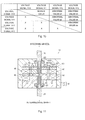
FIG. 7 is a table that shows an example of outputs from a first resolver provided in the torque sensor according to the embodiment; -
FIG. 8 is a table that shows another example of outputs from the first resolver provided in the torque sensor according to the embodiment; -
FIG. 9 is a flowchart that shows the procedure of a process of computing a steering angle of a steering wheel with the use of the torque sensor according to the embodiment; -
FIG. 10 is a table that shows an example of outputs from the first resolver in a torque sensor according to an alternative embodiment of the invention; -
FIG. 11 is a sectional view that shows the sectional structure of the torque sensor according to the alternative embodiment of the invention; -
FIG. 12 is a sectional view that shows the sectional structure of a torque sensor according to another alternative embodiment of the invention; and -
FIG. 13 is a plan view that shows an example of a rotation angle detection device according to the invention. - Hereinafter, a torque sensor according to an embodiment of the invention will be described with reference to
FIG. 1 to FIG. 9 . In the embodiment, the torque sensor according to the invention is used as a torque sensor of an electric power steering system for a vehicle. - As shown in
FIG. 1 , when a steering wheel 1 is operated by a driver, asteering shaft 2 rotates on the basis of a steering force applied to the steering wheel 1. Thesteering shaft 2 is formed of acolumn shaft 3, anintermediate shaft 4 and apinion shaft 5. The rotation of thesteering shaft 2 is converted into a linear motion of arack shaft 7 via a rack-and-pinion mechanism 6. The reciprocal linear motion of therack shaft 7 is transmitted to steeredwheels 9 viatie rods 8 coupled to respective ends of therack shaft 7. As a result, the steered angle of the steeredwheels 9 is changed. - In the thus configured vehicle, an electric
power steering system 10 according to the present embodiment is structured such that an electric motor 11 is coupled to thecolumn shaft 3 via aspeed reduction mechanism 12. The electricpower steering system 10 reduces the speed of rotation of the electric motor 11 with the use of thespeed reduction mechanism 12 and then transmits the rotation with a reduced speed to thecolumn shaft 3. In this way, motor torque is applied to the steering system as assist force. - In addition, the vehicle includes various sensors that detect the state of the vehicle and the operation amount of the steering wheel 1. For example, the vehicle includes a
vehicle speed sensor 13 that detects a vehicle speed. In addition, atorque sensor 14 is provided on thesteering shaft 2. Thetorque sensor 14 detects a torque that acts on theshaft 2, that is, a steering torque applied to the steering wheel 1 by the driver. Thetorque sensor 14 is used to detect the rotation angle (including an absolute rotation angle that is larger than or equal to 360 degrees) of thesteering shaft 2, that is, the steering angle of the steering wheel 1. The outputs from thesesensors ECU 15. The ECU 15 is mainly formed of a microcomputer, and collectively controls driving of the electric motor 11. The ECU 15 calculates a target torque that is a target value of steering torque that is applied by the driver on the basis of the vehicle speed and steering torque detected by the sensors, and executes feedback control on a current that is supplied to the electric motor 11 such that the steering torque detected by thetorque sensor 14 coincides with the target torque. - Next, the structure of the
torque sensor 14 will be described in detail with reference toFIG. 2 . As shown inFIG. 2 , thecolumn shaft 3 to which thetorque sensor 14 is fitted is configured such that aninput shaft 20 that may function as a first rotary body and alower shaft 21 that may function as a second rotary body are coupled to each other via atorsion bar 22 along the same axis. Theinput shaft 20 is rotatably supported by abearing 80 provided in an upper portion of ahousing 30. The upper end portion of theinput shaft 20 is coupled to the steering wheel 1. Thelower shaft 21 is rotatably supported by abearing 81 provided in a lower portion of thehousing 30. The lower end portion of thelower shaft 21 is coupled to theintermediate shaft 4. With this configuration, when steering force applied to the steering wheel 1 by the driver is transmitted to theinput shaft 20, thetorsion bar 22 is twisted and deformed when the steering torque is transmitted to thelower shaft 21 via thetorsion bar 22. That is, a rotation angular difference based on the steering torque is generated between theinput shaft 20 and thelower shaft 21. - The
housing 30 is formed of a box-shapedfirst housing 31 and asecond housing 32. Thebearing 80 is provided in thefirst housing 31, and the lower side of thefirst housing 31 is open. Thebearing 81 is provided in thesecond housing 32, and thesecond housing 32 closes the opening of thefirst housing 31. In this way, by forming thehousing 30 as a splittable member formed of two portions, it is easy to assemble thehousing 30. Thetorque sensor 14 is accommodated inside thehousing 30. Thetorque sensor 14 includes afirst resolver 40 and asecond resolver 50. Thefirst resolver 40 may function as a first rotation angle detection device that detects the rotation angle of theinput shaft 20. Thesecond resolver 50 may function as a second rotation angle detection device that detects the rotation angle of thelower shaft 21. - The
first resolver 40 is formed of arotor 41 and anannular stator 42. Therotor 41 is fixed to the lower end portion of theinput shaft 20, and rotates together with theinput shaft 20. Thestator 42 is fixed to thehousing 30, and surrounds therotor 41. Therotor 41 is made of a magnetic material. As shown inFIG. 3 , five bulge portions are formed on the outer periphery of therotor 41. That is, the multiplication factor of angle of thefirst resolver 40 is set to "5X". Note that thehousing 30 is not shown inFIG. 3 . Thestator 42 is formed of astator core 44, an exciting winding coil We and six output winding coils W1 to W6. Thestator core 44 is made of a magnetic material, and has twelve teeth T1 to T12 at angular intervals of 30° such that the teeth T1 to T12 face therotor 41. The exciting winding coil We and the six output winding coils W1 to W6 are wound around these teeth T1 to T12 as described in the following (a1) to (a7). - (a1) The exciting winding coil We is wound around all the teeth T1 to T12.
- (a2) The first output winding coil W1 is wound around the tooth T1 and the tooth T7 that faces the tooth T1.
- (a3) The second output winding coil W2 is wound around the tooth T2 and the tooth T8 that faces the tooth T2.
- (a4) The third output winding coil W3 is wound around the tooth T5 and the tooth T11 that faces the tooth T5.
- (a5) The fourth output winding coil W4 is wound around the tooth T6 and the tooth T12 that faces the tooth T6.
- (a6) The fifth output winding coil W5 is wound around the tooth T9 and the tooth T3 that faces the tooth T9.
- (a7) The sixth output winding coil W6 is wound around the tooth T10 and the tooth T4 that faces the tooth T10.
- In the
first resolver 40, when an exciting voltage Ve (= E×sin(ωt)) is applied to the exciting winding coil We, alternating fields are respectively applied from the exciting winding coil We to the output winding coils W1 to W6. "E" denotes amplitude, "ω" denotes angular frequency, and "t" denotes time. On the other hand, when therotor 41 rotates, distances between therotor 41 and the teeth T1 to T12 change on the basis of the positions of the bulge portions of therotor 41. Therefore, fields respectively applied from the exciting winding coil We to the output winding coils W1 to W6 change. Thus, voltage signals V1 to V6 based on the rotation angle (electric angle) θe of therotor 41 as described in the following (b1) to (b6) are output from the output winding coils W1 to W6, respectively. Note that "K" denotes transformer ratio. - (b1) A voltage signal V1 (= Ve×K×sin(θe)) is output from the first output winding coil W1.
- (b2) A voltage signal V2 (= Ve×K×sin(θe+30°)) is output from the second output winding coil W2.
- (b3) A voltage signal V3 (= Ve×K×sin(θe+120°)) is output from the third output winding coil W3.
- (b4) A voltage signal V4 (= Ve×K×sin(θe+150°)) is output from the fourth output winding coil W4.
- (b5) A voltage signal V5 (= Ve×K×sin(θe+240°)) is output from the fifth output winding coil W5.
- (b6) A voltage signal V6 (= Ve×K×sin(θe+270°)) is output from the sixth output winding coil W6.
- In this way, in the
first resolver 40, the exciting winding coil We and therotor 41 may function as a magnetic field generation unit, and the first to sixth output winding coils W1 to W6 may function as a magnetic field detection unit. The six-phase voltage signals V1 to V6 output from thefirst resolver 40 are input into theECU 15. - As shown in
FIG. 2 , thesecond resolver 50 is provided at the upper end portion of thelower shaft 21. Thesecond resolver 50 detects the rotation angle of thelower shaft 21. Thesecond resolver 50 is formed of arotor 51 and anannular stator 52. Therotor 51 is fixed to the upper end portion of thelower shaft 21, and integrally rotates with thelower shaft 21. Thestator 52 is fixed to thehousing 30, and surrounds therotor 51. Because thesecond resolver 50 has basically the same structure as that of thefirst resolver 40, the detailed description is omitted. Note that the multiplication factor of angle of thesecond resolver 50 is set to "4X". Voltage signals output from thesecond resolver 50 are also input into theECU 15. - A
planetary gear mechanism 60 is provided at the upper portion of thefirst resolver 40. As shown inFIG. 4 , theplanetary gear mechanism 60 is formed of asun gear 61, aninternal gear 62 and aplanetary gear 63. Thesun gear 61 is fixed to theinput shaft 20, and rotates together with theinput shaft 20. Theinternal gear 62 is provided so as to surround thesun gear 61, and is fixed in the housing 30 (not shown). Theplanetary gear 63 is in mesh with thesun gear 61 and theinternal gear 62. Note that thehousing 30 is not shown inFIG. 4 . - Each of the
gears 61 to 63 is formed of a bevel gear. As shown inFIG. 2 , the outer periphery of thesun gear 61, on which teeth are formed, has such a shape that the diameter increases toward thefirst resolver 40. The inner periphery of theinternal gear 62, on which teeth are formed, has such a shape that the diameter decreases toward thefirst resolver 40. With this configuration, a clearance between thesun gear 61 and theinternal gear 62 becomes narrower toward thefirst resolver 40. Theplanetary gear 63 is in mesh with thesun gear 61 and theinternal gear 62 with the distal end portion of theplanetary gear 63 oriented downward. With this configuration, movement of theplanetary gear 63 toward thefirst resolver 40 is restricted. Note that thesun gear 61 and theinternal gear 62 each are made of a non-magnetic material. - On the other hand, the
planetary gear 63 is basically made of a magnetic material, and only part of theplanetary gear 63, at which teeth are formed, is molded from resin. By molding the part of theplanetary gear 63, at which teeth are formed, from resin, occurrence of abnormal noise between theplanetary gear 63 and thesun gear 61 and between theplanetary gear 63 and theinternal gear 62 is suppressed. Ashaft portion 63a is formed on the upper face of theplanetary gear 63. Theshaft portion 63a is fitted in agroove 33 formed in the inner wall surface of thehousing 30. - As shown in
FIG. 5 , thegroove 33 is formed in a circular shape along the orbital path of theplanetary gear 63. Thus, theplanetary gear 63 is supported by thegroove 33 so as to be able to revolve around thesun gear 61. In theplanetary gear mechanism 60, the number of teeth of thesun gear 61 is set to "40" and the number of teeth of the internal gear is set to "50". As a result, while thesun gear 61 makes one rotation, that is, while theinput shaft 20 makes one rotation, theplanetary gear 63 makes 5/9 (= 50/(50+40)) revolution around thesun gear 61. With the thus structuredplanetary gear mechanism 60, it is possible to hold theplanetary gear 63 between thehousing 30 and thesun gear 61 and between thehousing 30 and theinternal gear 62. Therefore, it is possible to reliably and accurately theplanetary gear 63 without providing a support structure dedicated to the planetary gear. - As shown in
FIG. 2 , anannular stopper 70 for restricting axial movement of thestator 42 is provided between thestator 42 of thefirst resolver 40 and thestator 52 of thesecond resolver 50, and anannular stopper 71 for restricting axial movement of thestator 52 is provided between thestator 52 of thesecond resolver 50 and thesecond housing 32. - With the above-described structure of the
torque sensor 14, as shown inFIG. 6 , at the time of assembling thetorque sensor 14, if theplanetary gear mechanism 60, thefirst resolver 40, and the like, are sequentially accommodated into thefirst housing 31 with the opening of thefirst housing 31 with the opening of thefirst housing 31 oriented upward, it is possible to easily fit the component elements to thefirst housing 31. This facilitates the assembly of thetorque sensor 14. - The
ECU 15 executes known arctangent computation on the basis of two voltage signals among the voltage signals V1 to V6 output from thefirst resolver 40. In this way, the rotation angle (electric angle) of therotor 41, that is, the rotation angle (electric angle) θes of theinput shaft 20, is obtained. In addition, theECU 15 also executes arctangent computation on the basis of the voltage signals output from thesecond resolver 50. In this way, the rotation angle (electric angle) θep of thelower shaft 21 is also obtained. Then, theECU 15 computes the difference between the rotation angle θes of theinput shaft 20 and the rotation angle θep of thelower shaft 21, and then obtains a steering torque by multiplying the computed difference by the spring constant of thetorsion bar 22. - In addition, the
ECU 15 obtains the steering angle of the steering wheel 1 by detecting the absolute rotation angle θea of theinput shaft 20 on the basis of the voltage signals V1 to V6 output from thefirst resolver 40. In this way, in the present embodiment, theECU 15 serves as rotation angle detecting means for detecting the steering angle of the steering wheel 1. - Next, the principle of detection of the absolute rotation angle (electric angle) θea of the
input shaft 20 will be described with reference toFIG. 3, FIG. 4 andFIG. 7 . The description will be provided on the assumption that when the steering wheel 1 is located at a neutral position, theplanetary gear 63 is located at a reference position indicated by long dashed double-short dashed line inFIG. 4 . InFIG. 4 , a revolving angle is denoted by θp. The revolving angle θp is an angle formed between a line (dashed line inFIG. 4 ) that connects a revolving axis with the center of theplanetary gear 63 at the reference position and a line (dashed line) that connects the revolving axis with the center of theplanetary gear 63 at a revolving position when theplanetary gear 63 has revolved in a direction indicated by an arrow a from the reference position indicated by the long dashed double-short dashed line inFIG. 4 . In addition,FIG. 4 shows the absolute rotation angle (electric angle) θea of theinput shaft 20 in the direction indicated by the arrow a from the reference position of theinput shaft 20, which is the position of theinput shaft 20 when the steering wheel 1 is at the neutral position. Furthermore,FIG. 3 shows the rotation angle θe of therotor 41 in the direction indicated by the arrow a from the reference position of therotor 41, which is the position of therotor 41 when the steering wheel 1 is at the neutral position. In addition, inFIG. 3 and FIG. 4 , the orbital path of the planetary gear 63 (more specifically, the orbital path of a central axis m of the planetary gear 63) is indicated by long dashed short dashed line. - For example, when the steering wheel 1 is rotated "202.5°" by the driver, the
input shaft 20 also rotates "202.5°" in absolute angle (mechanical angle). In this case, as shown inFIG. 4 , the revolving angle θp of theplanetary gear 63 is "90° (= 202.5°×4/9)". Therefore, theplanetary gear 63 comes close to the tooth T4 as indicated by long dashed double-short dashed line inFIG. 3 . Thus, the magnetic field applied to the sixth output winding coil W6 changes under the influence of theplanetary gear 63. Specifically, because magnetic paths around the sixth output winding coil W6 increase, magnetic fluxes applied to the sixth output winding coil W6 increase and a magnetic resistance in the sixth output winding coil W6 decreases. Therefore, the magnitude of the voltage signal V6 output from the sixth output winding coil W6 is larger than the magnitude of a normal voltage signal described in the above (b6), and the voltage signal V6 indicates an abnormal value. - Then, the
ECU 15 compares the magnitudes of the voltage signals V1 to V6 of the first to sixth output winding coils W1 to W6 with a predetermined threshold to identify an output winding coil that outputs an abnormal voltage signal, and determines that theplanetary gear 63 is located at a position corresponding to the tooth around which the identified output winding coil is wound. According to the above determination method, for example, when the magnitude of the voltage signal output from the sixth output winding coil W6 is larger than the threshold, theECU 15 determines that the revolving angle θp of theplanetary gear 63 is "90°" corresponding to the tooth T4 or "270°" corresponding to the tooth T10. - On the other hand, when the
input shaft 20 rotates "202.5°" in absolute angle (mechanical angle), in thefirst resolver 40, the rotation angle (electric angle) θe of therotor 41 shown inFIG. 3 is "1012.5 (= 202.5°×5)". Therefore, the rotation angle (electric angle) θes of theinput shaft 20, which is computed from a combination of two of the voltage signals V1 to V6 of thefirst resolver 40, should be usually "292.5° (= 1012° - 360×2°)". However, when the magnitude of the voltage signal V6 output from the sixth output winding coil W6 is abnormal, only the rotation angle θes that is computed from a combination with the voltage signal V6 is an abnormal angle. Therefore, as shown inFIG. 7 , among the fifteen rotation angles θes that are computed from the voltage signals V1 to V6, only the five rotation angles θes computed from a combination with the voltage signal V6 are angles other than "292.5°". Therefore, theECU 15 executes majority operation on the fifteen rotation angles θes computed from the voltage signals V1 to V6 of thefirst resolver 40 to detect a proper rotation angle θes of theinput shaft 20. That is, when the fifteen rotation angles θes as shown inFIG. 7 are computed, ten rotation angles θes indicate "292.5°", and five rotation angles θes indicate other angles, so it is determined that the rotation angle θes of theinput shaft 20 is "292.5°". - For example, when the revolving angle (mechanical angle) θp of the
planetary gear 63 is "105°", that is, when theplanetary gear 63 is located between the tooth T4 and the tooth T5, theplanetary gear 63 comes close to not only the sixth output winding coil W6 but also the third output winding coil W3. Therefore, the voltage signals V3 and V6 indicate abnormal values. In this case, as shown inFIG. 8 , among fifteen rotation angles θes computed by theECU 15, nine rotation angles computed from a combination of the voltage signals V3 and V6 are abnormal values a to i that are different from each other, and the remaining six rotation angles are normal values. Therefore, through a majority operation, it is possible to detect the rotation angle θes of theinput shaft 20. - Through the above described determination method, the
ECU 15 detects that the revolving angle θp of theplanetary gear 63 is "90°" or "270°" in mechanical angle and the rotation angle (electric angle) θes of theinput shaft 20 is "292.5°". Then, theECU 15 computes the absolute rotation angle (electric angle) θea of theinput shaft 20, including multiple-turn rotation, from these detection results as follows. - First, the following relational expression indicated by Equation 1 below is established among the absolute rotation angle (electric angle) θea of the
input shaft 20, the rotation angle (electric angle) θes of theinput shaft 20, which is detected through a majority operation, and the revolving angle (mechanical angle) θp of theplanetary gear 63. Note that "Np" denotes the number of revolutions of theplanetary gear 63 during one rotation of theinput shaft 20, and "Ax" denotes the multiplication factor of angle of thefirst resolver 40.
where n is an integer. - Then, the
ECU 15 sequentially changes the value of "n" to obtain "n" at which the revolving angle (mechanical angle) θp of theplanetary gear 63 satisfies "90° - Δθ ≤ θp ≤ 90° + Δθ" or "270° - Δθ ≤ θp ≤ 270° + Δθ". Note that "Δθ" is a constant set in advance as an angular range in which the magnitude of the voltage signals V1 to V6 output from the output winding coils W1 to W6 are expected to exceed a threshold, and, in the present embodiment, "7.5°" is employed. Thus, the revolving angle (mechanical angle) θp of theplanetary gear 63 is determined through, for example, the following computations (c1) and (c2). - (c1) When n = 1,

- (c2) When n = 2,

- When the computation of (c2) is executed, the computed revolving angle (mechanical angle) θp satisfies "90° - Δθ ≤ θp ≤ 90° + Δθ". Therefore, it is found that "n = 2" from the computation result of the computation (c2). That is, it is found that the
input shaft 20 is rotated by two periods in the phase of electric angle, that is, the rotational speed of theinput shaft 20 is "0.4 (= 2/5)". Thus, theECU 15 detects that the absolute rotation angle (electric angle) θea of theinput shaft 20 is "1012.5 (= 292.5 + 360°×2)". -
FIG. 9 shows, as a flowchart, a process of computing the steering angle of the steering wheel 1 with the use of theECU 15 on the basis of the above-described method of detecting the absolute rotation angle (electric angle) θea of theinput shaft 20. Hereinafter, an operation example (operation) of thefirst resolver 40 will be described with reference toFIG. 9 . Actually, the process shown inFIG. 9 is repeatedly executed at predetermined computation cycles. - As shown in
FIG. 9 , in the process, first, it is identified which of the voltage signals V1 to V6 output from thefirst resolver 40 indicates an abnormal value by comparing the voltage signals V1 to V6 with the predetermined threshold (step S1). The revolving angle (mechanical angle) θp of theplanetary gear 63 is detected form the identified result (step S2). Subsequently, fifteen rotation angles (electric angles) θes of therotor 41 are each computed from combinations of two of the voltage signals V1 to V6 (step S3). By performing a majority operation on the computed fifteen rotation angles (electric angles) θes of therotor 41, the rotation angle (electric angle) θes of theinput shaft 20 is detected (step S4). Subsequently, the absolute rotation angle (electric angle) θea of theinput shaft 20 is computed on the basis of the detected revolving angle (mechanical angle) θp of theplanetary gear 63 and the detected rotation angle (electric angle) θes of the input shaft 20 (step S5). Specifically, by searching for "n" that satisfies Equation 1, the absolute rotation angle (electric angle) θea of theinput shaft 20 is computed. Then, the steering angle (mechanical angle) of the steering wheel 1 is computed on the basis of the multiplication factor of angle of thefirst resolver 40 from the computed absolute rotation angle (electric angle) θea of the input shaft 20 (step S6). - With the
above torque sensor 14, it is possible to detect the steering angle of the steering wheel 1 just by providing thefirst resolver 40 with theplanetary gear mechanism 60. Therefore, in comparison with the case where a rotation speed detection device that detects the rotational speed of theinput shaft 20 is provided, it is possible to simplify the structure. - As described above, with the torque sensor according to the present embodiment, the following advantageous effects are obtained.
- (1) The
first resolver 40 is provided with theplanetary gear mechanism 60 includes: thesun gear 61 that rotates together with theinput shaft 20; theplanetary gear 63 that is made of a magnetic material and that revolves around thesun gear 61 in accordance with the rotation of thesun gear 61; and theinternal gear 62 that is in mesh with theplanetary gear 63. In addition, the rotation angle θes of theinput shaft 20 and the revolving angle θp of theplanetary gear 63 are detected on the basis of the voltage signals V1 to V6 respectively output from the first to sixth output winding coils W1 to W6 provided in thefirst resolver 40. Then, the absolute rotation angle θea of theinput shaft 20 is computed on the basis of the rotation angle θes of theinput shaft 20 and the revolving angle θp of theplanetary gear 63, and the steering angle of the steering wheel 1 is obtained from the computed result. In this way, it is possible to detect the steering angle of the steering wheel 1 just by providing thefirst resolver 40 with theplanetary gear mechanism 60. Therefore, in comparison with the case where a rotation speed detection device that detects the rotational speed of theinput shaft 20 is provided, it is possible to simplify the structure. - (2) The revolving angle θp of the planetary gear is detected by identifying which of the voltage signals V1 to V6 respectively output from the first to sixth output winding coils W1 to W6 of the
first resolver 40 indicates an abnormal value. Thus, it is possible to easily detect the revolving angle θp of theplanetary gear 63. - (3) The rotation angle θes of the
input shaft 20 is detected by computing a plurality of rotation angles θes of theinput shaft 20 from combinations of two of the voltage signals V1 to V6 output from thefirst resolver 40 and performing a majority operation on the computed results. In this way, it is possible to easily detect the rotation angle θes of theinput shaft 20. - (4) The
planetary gear 63 is held between thehousing 30 and thesun gear 61 and between thehousing 30 and theinternal gear 62. Therefore, without providing a member for supporting theplanetary gear 63, it is possible to easily and accurately support theplanetary gear 63. Therefore, it is possible to simplify the structure. - (5) The steering angle of the steering wheel 1 is detected with the use of the
first resolver 40 provided in thetorque sensor 14. Therefore, it is not necessary to provide a sensor that detects the steering angle of the steering wheel 1. - Note that the above-described embodiment may be modified into the following alternative embodiments.
- In the above-described embodiment, the
first resolver 40 outputs six-phase voltage signals. However, the number of output voltage signals may be changed as needed. However, when thefirst resolver 40 outputs four or smaller phases voltage signals, there is the following concern that will be described on the assumption that when thefirst resolver 40 is configured to output four-phase voltage signals V10 to V13, the two voltage signals V12 and V13 among the four-phase voltage signals V10 to V13 indicate abnormal values because theplanetary gear 63 is located between the two teeth. In this case, as shown inFIG. 10 , among six rotation angles θes that are computed from combinations of two of the four-phase voltage signals V10 to V13, the number of the computed results that indicate abnormal values b1 to b5 is five, and only one computed result indicates a normal value. Therefore, it may not be possible to identify the rotation angle θes of therotor 41 according to the method of performing a majority operation on the computed results. In addition, in the case where thefirst resolver 40 has a three-phase output structure, if two voltage signals among the three outputs indicate abnormal values, there is no computed result that indicates a normal value. Therefore, it may also not be possible to identify the rotation angle θes of therotor 41. Therefore, the number of voltage signals output from thefirst resolver 40 is desirably larger than or equal to five. Note that, even when thefirst resolver 40 has a three-phase output structure or four-phase output structure, for example, if the output winding coils are apart from each other, it is possible to avoid a situation where theplanetary gear 63 influences two output winding coils. Thus, with the above structure, it is possible to identify the rotation angle θes of therotor 41 according to the method of performing a majority operation on computed results. - The multiplication factor of angle of the
first resolver 40 may be changed as needed. - In the above-described embodiment, the
gears 61 to 63 of theplanetary gear mechanism 60 each are formed of a bevel gear. Alternatively, as shown inFIG. 11 , thegears 61 to 63 each may be formed of a spur gear. In this case, as shown in the drawing, providing aflange portion 63b between a portion, at which the teeth of theplanetary gear 63 are formed, and theshaft portion 63a is effective. Because movement of theplanetary gear 63 toward thefirst resolver 40 is restricted by theflange portion 63b, it is possible to accurately keep the position of theplanetary gear 63. - In the above-described embodiment, the
internal gear 62 is fixed inside thehousing 30, and theplanetary gear 63 is in mesh with theinternal gear 62. Alternatively, theinternal gear 62 may be replaced with an external gear. In addition, the planetary gear may be supported by a planetary carrier such that the planetary gear is rotatable about its axis and revolvable around thesun gear 61.FIG. 12 shows an embodiment in which external teeth are formed on theshaft portion 63a of theplanetary gear 63. In addition, anexternal gear 64 is fixed to a portion of the inner wall of thehousing 30 above thesun gear 61. Theexternal gear 64 is in mesh with the external teeth formed on theshaft portion 63a of theplanetary gear 63. Note that aninsertion hole 64a is formed at the center portion of theexternal gear 64, and theinput shaft 20 is passed through theinsertion hole 64a. Further, aplanetary carrier 65 that is supported by theinput shaft 21 via abearing 82 is provided below thesun gear 61, and theplanetary gear 63 is supported by theplanetary carrier 65 such that theplanetary gear 63 is rotatable about its axis and revolvable around thesun gear 61. With the above configuration as well, it is possible to revolve theplanetary gear 63 in accordance with the rotation of theinput shaft 20. Therefore, similar advantageous effects to those of the above-described embodiment are obtained. - In the above-described embodiment, the revolving position of the
planetary gear 63 is detected as one of positions of two teeth that face each other, that is, candidate two positions as the revolving position of theplanetary gear 63 are detected, and then the absolute rotation angle θea of theinput shaft 20 is detected through the above computations (c1) and (c2) indicated as an example. Alternatively, it may be further identified which of the positions of the two teeth that face each other is the revolving position of theplanetary gear 63. Specifically, as shown inFIG. 3 , the situation where theplanetary gear 63 comes close to the first output winding coil W1 presumably includes two situations, that is, the situation where theplanetary gear 63 comes close to the tooth T1 and the situation where theplanetary gear 63 comes close to the tooth T7. Between these two situations, the rotation angle θe of therotor 41 is different, and therefore the magnitude of the voltage signal V1 output from the first output winding coil W1 is different. By utilizing this fact, for example, when the output winding coil to which theplanetary gear 63 comes close is identified, it is possible to identify at which of the two teeth that face each other theplanetary gear 63 is located, on the basis of the magnitude of the voltage signal output from the identified output winding coil. When the position of theplanetary gear 63 is identified in this way, it is possible to further accurately detect the absolute rotation angle θea of theinput shaft 20. - In the above-described embodiment, the
gears 61 to 63 of theplanetary gear mechanism 60 each are formed of a bevel gear, and theplanetary gear 63 is retained by inserting theshaft portion 63a of theplanetary gear 63 in thegroove 33 formed on thehousing 30. Instead of such retainment of theplanetary gear 63 by thegroove 33 of thehousing 30, for example, theplanetary gear 63 may be supported by bringing another planetary gear made of a non-magnetic material, other than theplanetary gear 63, into mesh with thesun gear 61 and theinternal gear 62 and then coupling the other planetary gear to theplanetary gear 63 by a planetary carrier. - In the above-described embodiment, the
planetary gear 63 is made of a magnetic material. Alternatively, theplanetary gear 63 may be made of a non-magnetic material, such as aluminum. Theplanetary gear 63 may be made of any material as long as the material changes magnetic fields formed by the exciting winding coil We. - In the above-described embodiment, the structure in which the
planetary gear 63 makes 4/9 revolution around thesun gear 61 while theinput shaft 20 makes one rotation is employed. However, the number of revolutions of theplanetary gear 63 may be changed as needed. As long as a structure in which theplanetary gear 63 makes a revolution of non-integer numbers around thesun gear 61 while theinput shaft 20 makes one rotation is employed, it is possible to detect the absolute rotation angle of theinput shaft 20 on the basis of the revolving angle of theplanetary gear 63. - In the above-described embodiment, the torque sensor according to the invention is applied to the electric power steering system. However, the invention may be applied to any device that includes a torque sensor. In addition, the invention may be applied to not only a torque sensor but also any resolver that detects the rotation angle of a rotary body.
- In the above-described embodiment, the rotation angle detection device according to the invention is applied to the resolver. Alternatively, the invention may be applied to rotation angle detection devices, such as a rotation angle detection device that detects the rotation angle of a rotary body by utilizing, for example, a Hall element or a magnetoresistive element.
FIG. 13 shows an example of a rotation angle detection device that utilizes a Hall element. As shown inFIG. 13 , the rotation angle detection device has the multiplication factor of angle "5X", and includes arotor 90 and astator 91. Therotor 90 is formed of ten-pole magnets, and rotates together with theinput shaft 20. Thestator 91 is fixed to thehousing 30, and surrounds therotor 90. SixHall elements 92a to 92f are attached to the inner wall of thestator 91 at equal intervals in the circumferential direction of therotor 90. The rotation angle detection device detects the rotation angle (electric angle) of therotor 90, that is, the rotation angle (electric angle) of theinput shaft 20, on the basis of outputs from theHall elements 92a to 92f. In the thus configured rotation angle detection device, when the above-describedplanetary gear mechanism 60 is provided, it is possible to cause theplanetary gear 63 to revolve near therotor 90 and theHall elements 92a to 92f when therotor 90 rotates as indicated by long dashed short dashed line in the drawing. Thus, it is possible to obtain the rotation angle (including the absolute rotation angle larger than or equal to 360 degrees) of theinput shaft 20 on the basis of the outputs from the Hall elements 91a to 91f. That is, similar advantageous effects to those of the above-described embodiment are obtained. As long as a rotation angle detection device includes a plurality of magnetic field detection units arranged in a rotation direction of a rotary body and a magnetic field generation unit that generates magnetic fields respectively applied to these magnetic field detection units and detects the rotation angle of the rotary body by detecting changes that occur in the magnetic fields with the rotation of the rotor with the use of the magnetic field detection units, it is possible to apply the rotation angle detection device according to the invention.
Claims (6)
- A rotation angle detection device, comprising:a plurality of magnetic field detection units that are arranged along a rotation direction of a rotary body;a magnetic field generation unit that generates magnetic fields that are respectively applied to the plurality of magnetic field detection units;a sun gear that rotates together with the rotary body; anda planetary gear that is made of a material capable of changing the magnetic fields, and that revolves around the sun gear in accordance with rotation of the sun gear, whereinthe magnetic field generation unit rotates relative to the plurality of magnetic field detection units in accordance with rotation of the rotary body, andthe planetary gear revolves along an orbital path that corresponds to arrangement of the plurality of magnetic field detection units.
- The rotation angle detection device according to claim 1, wherein
a position of the planetary gear with respect to the plurality of magnetic field detection units is detected by identifying which of outputs from the plurality of magnetic field detection units indicates an abnormal value. - The rotation angle detection device according to claim 1 or 2, wherein
a rotation angle of the rotary body is detected by computing a plurality of rotation angles of the rotary body based on outputs from the plurality of magnetic field detection units and then performing a majority operation on the plurality of computed rotation angles. - The rotation angle detection device according to claim 3, wherein
the rotation angle of the rotary body is detected based on combinations of two of the outputs from the plurality of magnetic field detection units, and
the number of the magnetic field detection units is five or more. - The rotation angle detection device according to any one of claims 1 to 4, further comprising:a housing that supports the planetary gear such that the planetary gear is revolvable around the sun gear; andan internal gear that is provided so as to surround the sun gear and that is in mesh with the planetary gear, whereinthe planetary gear is held between the housing and the sun gear and between the housing and the internal gear.
- A torque sensor, comprising:a first rotation angle detection device that detects a rotation angle of a first rotary body; anda second rotation angle detection device that detects a rotation angle of a second rotary body that is coaxially coupled to the first rotary body via a torsion bar, whereinthe torque sensor detects a torque that is applied to the first rotary body based on a difference between the rotation angle of the first rotary body and the rotation angle of the second rotary body, andthe rotation angle detection device according to any one of claims 1 to 5 is used as the first rotation angle detection device.
Applications Claiming Priority (1)
| Application Number | Priority Date | Filing Date | Title |
|---|---|---|---|
| JP2011241988A JP2013096930A (en) | 2011-11-04 | 2011-11-04 | Rotation angle detection apparatus and torque sensor |
Publications (1)
| Publication Number | Publication Date |
|---|---|
| EP2589935A2 true EP2589935A2 (en) | 2013-05-08 |
Family
ID=47071167
Family Applications (1)
| Application Number | Title | Priority Date | Filing Date |
|---|---|---|---|
| EP12189002.4A Withdrawn EP2589935A2 (en) | 2011-11-04 | 2012-10-18 | Rotation angle detection device and torque sensor |
Country Status (4)
| Country | Link |
|---|---|
| US (1) | US20130113471A1 (en) |
| EP (1) | EP2589935A2 (en) |
| JP (1) | JP2013096930A (en) |
| CN (1) | CN103085861A (en) |
Families Citing this family (13)
| Publication number | Priority date | Publication date | Assignee | Title |
|---|---|---|---|---|
| JP6373962B2 (en) | 2013-03-13 | 2018-08-15 | ティアックス エルエルシーTiax Llc | Torque sensor |
| CN103407489B (en) * | 2013-08-12 | 2016-07-06 | 长沙中联重科环卫机械有限公司 | Vehicle steering device and vehicle |
| CN103486965A (en) * | 2013-09-29 | 2014-01-01 | 杭州飞越汽车零部件有限公司 | Device for measuring steering angle and torque |
| JP5958572B2 (en) * | 2014-02-27 | 2016-08-02 | 株式会社デンソー | Rotation angle detection device and electric power steering device using the same |
| TWI579546B (en) * | 2015-12-18 | 2017-04-21 | 財團法人車輛研究測試中心 | Gear type torque sensing device |
| CN109844448A (en) * | 2016-10-19 | 2019-06-04 | 日本精工株式会社 | Sensor assembly structure, electric motor, and electric power steering device |
| JP2018072022A (en) * | 2016-10-25 | 2018-05-10 | クノールブレムゼ商用車システムジャパン株式会社 | Rotation detection device, gear shift unit, and transmission system |
| US10975717B2 (en) | 2016-12-19 | 2021-04-13 | General Electric Company | Torque monitoring device for a gas turbine engine |
| JP6926504B2 (en) * | 2017-02-10 | 2021-08-25 | 株式会社デンソー | Rotation detector |
| CN107628110A (en) * | 2017-09-29 | 2018-01-26 | 株洲易力达机电有限公司 | A kind of automobile electric power-assisted steering disk angle recognition method |
| US10800447B2 (en) * | 2018-08-24 | 2020-10-13 | Ford Global Technologies, Llc | Steering system with multiple controllers |
| EP3907473B1 (en) * | 2020-05-06 | 2022-08-24 | Baumer Electric AG | Angle measuring device for single and multiturn measurement |
| CN116568995B (en) * | 2020-12-11 | 2024-09-06 | 马渊马达株式会社 | Resolver |
Citations (1)
| Publication number | Priority date | Publication date | Assignee | Title |
|---|---|---|---|---|
| JP2004245642A (en) | 2003-02-12 | 2004-09-02 | Koyo Seiko Co Ltd | Rotation angle detection apparatus and torque detection apparatus in steering apparatus |
-
2011
- 2011-11-04 JP JP2011241988A patent/JP2013096930A/en active Pending
-
2012
- 2012-10-16 US US13/652,659 patent/US20130113471A1/en not_active Abandoned
- 2012-10-18 EP EP12189002.4A patent/EP2589935A2/en not_active Withdrawn
- 2012-10-31 CN CN2012104287374A patent/CN103085861A/en active Pending
Patent Citations (1)
| Publication number | Priority date | Publication date | Assignee | Title |
|---|---|---|---|---|
| JP2004245642A (en) | 2003-02-12 | 2004-09-02 | Koyo Seiko Co Ltd | Rotation angle detection apparatus and torque detection apparatus in steering apparatus |
Also Published As
| Publication number | Publication date |
|---|---|
| US20130113471A1 (en) | 2013-05-09 |
| CN103085861A (en) | 2013-05-08 |
| JP2013096930A (en) | 2013-05-20 |
Similar Documents
| Publication | Publication Date | Title |
|---|---|---|
| US20130113471A1 (en) | Rotation angle detection device and torque sensor | |
| US10035535B2 (en) | Relative angle detection device, torque sensor, electric power steering device and vehicle | |
| US9097509B2 (en) | Rotation angle sensor | |
| JP5616281B2 (en) | Torque sensor and power steering device | |
| US9212892B2 (en) | Steering angle sensor | |
| JP5679136B2 (en) | Rotation angle detection device and electric power steering device provided with rotation angle detection device | |
| EP3423333B1 (en) | Ripple minimization by proper as/ts magnet arrangement in electric power assisted steering apparatus | |
| US20150090051A1 (en) | Torque Index Sensor | |
| JP6669318B2 (en) | Electric power steering apparatus and method for detecting rotation angle of motor for electric power steering apparatus | |
| JP2017015696A (en) | Relative angle detection device, torque sensor, electric power steering device, and vehicle | |
| US20050236221A1 (en) | Absolute steering angle detection device and absolute steering angle detection method for electric power steering device | |
| US9989384B2 (en) | Measurement of motor rotor position or speed | |
| US9638509B2 (en) | Phase difference detector and rotation angle detection device including the same | |
| US20140158453A1 (en) | Rotation angle detection device and electric power steering system including the same | |
| US9658050B2 (en) | Rotation angle detection device | |
| JP2005274484A (en) | Angle detector | |
| JP6108009B2 (en) | Relative angle detection device, torque sensor, electric power steering device, and vehicle | |
| US9625249B2 (en) | Rotation angle detection device and electric power steering system including the same | |
| US6935194B2 (en) | Dual resolver device | |
| JP4882513B2 (en) | Rotation angle detection device and torque sensor | |
| US8942890B2 (en) | Torque detecting device and electric power steering system | |
| US20230194313A1 (en) | Angle detection apparatus | |
| JP2017040545A (en) | Rotation sensor-equipped bearing device, electric motor, torque sensor, electric power steering device, and vehicle provided with the rotation sensor-equipped bearing device | |
| JP2008051702A (en) | Torque detection device | |
| JP2007278924A (en) | Rotation angle detector |
Legal Events
| Date | Code | Title | Description |
|---|---|---|---|
| PUAI | Public reference made under article 153(3) epc to a published international application that has entered the european phase |
Free format text: ORIGINAL CODE: 0009012 |
|
| AK | Designated contracting states |
Kind code of ref document: A2 Designated state(s): AL AT BE BG CH CY CZ DE DK EE ES FI FR GB GR HR HU IE IS IT LI LT LU LV MC MK MT NL NO PL PT RO RS SE SI SK SM TR |
|
| AX | Request for extension of the european patent |
Extension state: BA ME |
|
| STAA | Information on the status of an ep patent application or granted ep patent |
Free format text: STATUS: THE APPLICATION HAS BEEN WITHDRAWN |
|
| 18W | Application withdrawn |
Effective date: 20140701 |