EP2589890B1 - A unit for a system - Google Patents
A unit for a system Download PDFInfo
- Publication number
- EP2589890B1 EP2589890B1 EP11008774.9A EP11008774A EP2589890B1 EP 2589890 B1 EP2589890 B1 EP 2589890B1 EP 11008774 A EP11008774 A EP 11008774A EP 2589890 B1 EP2589890 B1 EP 2589890B1
- Authority
- EP
- European Patent Office
- Prior art keywords
- frame
- opening
- socket
- compressible material
- collar
- Prior art date
- Legal status (The legal status is an assumption and is not a legal conclusion. Google has not performed a legal analysis and makes no representation as to the accuracy of the status listed.)
- Active
Links
Images

Classifications
-
- H—ELECTRICITY
- H02—GENERATION; CONVERSION OR DISTRIBUTION OF ELECTRIC POWER
- H02G—INSTALLATION OF ELECTRIC CABLES OR LINES, OR OF COMBINED OPTICAL AND ELECTRIC CABLES OR LINES
- H02G3/00—Installations of electric cables or lines or protective tubing therefor in or on buildings, equivalent structures or vehicles
- H02G3/02—Details
- H02G3/08—Distribution boxes; Connection or junction boxes
- H02G3/14—Fastening of cover or lid to box
-
- F—MECHANICAL ENGINEERING; LIGHTING; HEATING; WEAPONS; BLASTING
- F24—HEATING; RANGES; VENTILATING
- F24F—AIR-CONDITIONING; AIR-HUMIDIFICATION; VENTILATION; USE OF AIR CURRENTS FOR SCREENING
- F24F11/00—Control or safety arrangements
- F24F11/30—Control or safety arrangements for purposes related to the operation of the system, e.g. for safety or monitoring
-
- F—MECHANICAL ENGINEERING; LIGHTING; HEATING; WEAPONS; BLASTING
- F24—HEATING; RANGES; VENTILATING
- F24F—AIR-CONDITIONING; AIR-HUMIDIFICATION; VENTILATION; USE OF AIR CURRENTS FOR SCREENING
- F24F11/00—Control or safety arrangements
- F24F11/89—Arrangement or mounting of control or safety devices
-
- H—ELECTRICITY
- H02—GENERATION; CONVERSION OR DISTRIBUTION OF ELECTRIC POWER
- H02G—INSTALLATION OF ELECTRIC CABLES OR LINES, OR OF COMBINED OPTICAL AND ELECTRIC CABLES OR LINES
- H02G3/00—Installations of electric cables or lines or protective tubing therefor in or on buildings, equivalent structures or vehicles
- H02G3/02—Details
- H02G3/08—Distribution boxes; Connection or junction boxes
- H02G3/12—Distribution boxes; Connection or junction boxes for flush mounting
-
- F—MECHANICAL ENGINEERING; LIGHTING; HEATING; WEAPONS; BLASTING
- F24—HEATING; RANGES; VENTILATING
- F24F—AIR-CONDITIONING; AIR-HUMIDIFICATION; VENTILATION; USE OF AIR CURRENTS FOR SCREENING
- F24F2221/00—Details or features not otherwise provided for
- F24F2221/17—Details or features not otherwise provided for mounted in a wall
Definitions
- the invention relates to a unit comprising a socket forming a first part, a second part mountable on the socket, a frame between the socket and the second part, said frame having an opening surrounding a connection section of the two parts, wherein said opening is larger than said connecting section and said second part comprises a collar being larger than said opening.
- the invention is illustrated in connection with a unit used as a control unit for a system, in particular a heating or cooling system or any other system influencing conditions of the environment, like a ventilation system, a humidification system, a shading system against sunlight, and so on.
- a unit used as a control unit for a system in particular a heating or cooling system or any other system influencing conditions of the environment, like a ventilation system, a humidification system, a shading system against sunlight, and so on.
- a unit of the above mentioned type is known from EP 2 272 143 A1 , said document thereby discloses a unit according to the preamble of claim 1.
- An electrical installation equipment is flush-mounted in a wall and afterwards covered by an aesthetic frame.
- a mounting frame is placed in an opening of the aesthetic frame and engages a protruding rim of the electrical installation equipment.
- the mounting frame abuts against the aesthetic frame and thereby fixes the aesthetic frame on the wall to cover the electrical installation equipment.
- US 2010/101854 A1 shows a flush wall mount thermostat and in-set mounting plate for a heating, ventilation or air conditioning system.
- the mounting system comprises a housing for receiving electrical components with a front panel and a back panel coupled to each other.
- a mounting plate is connectable to said front and back plates by a flange of said housing that may be receive in a recess of the mounting plate.
- DE 10 2005 016082 A1 discloses an apparatus, e. g. a light switch, that may be mounted in a wall.
- a frame comprises protrusions that may engage recesses of the socket.
- a plate e.g. a switch button, may engage the socket using holding ribs.
- DE 10 2004 051928 A1 shows a housing with fixing elements.
- the housing may be inserted into an opening of a mounting plate.
- the fixing elements comprise feather elements that may engage an edge of the mounting plate once the housing has been inserted into the opening. Between the housing and the mounting plate an elastic sealing may be arranged.
- the first part is formed as a socket which is fixedly mounted in a wall of a room.
- a socket comprises functional parts which cannot be influenced by a user, like sensors, electrical connections, remote control switches and the like.
- the second part is mountable on the socket and comprises the "intelligent" part of the unit, e.g. elements which are used for setting and displaying parameters and the like.
- the frame is provided. Before mounting the second part on the socket the frame is arranged on the socket. The second part is inserted into the opening of the frame and then the second part is mounted on the socket.
- the task underlying the invention is to make it possible to use the unit in different environments.
- a compressible material is arranged between said collar and said frame, said compressible material being pressed against said frame by means of said collar, wherein said first part and said second part are connected by means of a catch mechanism, said catch mechanism having at least two locking positions, a distance between two adjacent positions being smaller than a thickness of the compressible material in an uncompressed state.
- each of the frames has an opening which is larger than the connecting section between the first part and the second part. Since the second part comprises a collar which is larger than said opening the opening is not visible although this opening is not completely filled by the connecting section of the two parts.
- the frame is held by the collar by friction. This has the additional advantage that the collar can be aligned with the second part even after mounting of the second part on the first part.
- a compressible material is arranged between said collar and said frame, said compressible material being pressed against said frame by means of said collar.
- Said compressible material can be rubber or an elastic plastic material.
- the compressible material defines a position of the frame relative to the wall or to the socket.
- said first part and said second part are connected by means of a catch mechanism, said catch mechanism having at least two locking positions, a distance between two adjacent locking positions being smaller than a thickness of the compressible material in an uncompressed state.
- said collar is pressed against said compressible material with a force generating a friction force between said frame and said collar, said friction force being greater than twice of the force created by the weight of the frame.
- said compressible material is in the form of a ring, said ring following the form of the opening.
- the compressible material is in the form of a ring it can be easily handled during mounting. After mounting it is not longer necessary to keep the material in the form a ring. Therefore it is possible to use a sequence of sections of the compressible material which are held together in the form of a ring before mounting.
- One possibility is to hold the compressible material together with the frame at a position near the socket and to insert the second part into the opening of the frame and fix the second part to the socket.
- the first part or socket has a protrusion which is inserted into the opening of the frame then the frame together with the ring of compressible material is guided over the protrusion and the second part is mounted thereafter. In this way it is possible to use different frames, even from a number of different manufacturers.
- said second part has display and/or operating means in an area on a side parallel to said opening, said area being larger than said opening. Since the second part has already a collar which is larger than the opening in the frame this collar can be used to enlarge the operating area of the second part thus making operation of the unit easier.
- the larger display and/or operating means are the easier it is for an user to input settings into the unit or to read information from the display.
- said display means comprise a touch screen.
- the touch screen can be made large enough to input the necessary settings with a finger of an user and to display at the same time the reaction of these settings.
- a unit 1 as shown in Fig. 1 is used to set and display parameters in a heating or cooling system.
- the unit 1 comprises a socket 2 which is also termed as "first part".
- the socket 2 is designed to be fixedly mounted in a wall of a room or a building.
- the socket 2 comprises parts like one or more sensors, electrical connections, switches and so on. These parts should not directly be actuated by a person.
- the unit 2 comprises a second part 3.
- the second part 3 comprises display and/or operating means 4 in the form of a touch screen and/or buttons, switches, LEDs or the like.
- a frame 5 is provided to be mounted between the socket 2 and the second part 3.
- This frame 5 comprises an opening 6.
- This opening 6 is larger than a connecting part 7 of the second part 3.
- This connecting part 7 is used to connect the second part 3 and the socket 2. To this end the connecting part 7 is inserted through the opening 6.
- the second part together with the frame 5 can then be mounted on the socket 2. Another possibility is to first position the frame on the socket 2 (or a wall in which the socket 2 is mounted) and to mount the second part 3 thereafter.
- Fig. 2 shows the unit 1 in a mounted state. However, the socket 2 is not built in a wall.
- a unit 1 can be used with a lot of different frames 5 thus making it possible to adapt the unit optically to different surroundings.
- the second part 3 comprises a collar 8 which is larger than the opening 6 of the frame 5. Therefore, the collar 8 covers more than the opening 6 of the frame 5.
- a compressible material 9 is arranged between the second part 3 and the frame 5, more precisely between the collar 8 and the frame 5.
- the compressible material 9 is pressed against the frame 5 by means of the collar 8 with a force generating a friction force between the frame 5 and the collar 8.
- the friction force is greater than twice of the force created by the weight of the frame 5. This is sufficient to hold the frame 5 in position even if the frame is mounted moveable in vertical direction, as shown in Fig. 2 . However, it is possible to adjust the position of the frame 5 even after mounting.
- the compressible material 9 is in the form of a ring, wherein the ring 9 follows the form of the opening 6. Therefore, it can be made sure that the compressible material 9 is always in contact with an inner edge 10 of the frame 5 surrounding the opening 6.
- the socket 2 comprises a first member 11 of a catch mechanism, said first member 11 having a number of teeth 12.
- the second part 3 comprises a second member 13 of the catch mechanism, wherein said second member 13 comprises a number of teeth 14.
- the pitch of the teeth 12, 14 is the same.
- At least one of the members 11, 13 can be elastically formed so that at least one tooth 14 of the second number 13 of the second part 3 catches behind a tooth 12 of the first member 11 of the catch mechanism.
- the two members 11, 13 together define at least two locking positions, the distance between two adjacent locking positions being defined by the distance of the tips of the teeth 12, 14.
- the distance between two adjacent locking positions is smaller than a thickness of the compressible material 9 in an uncompressed state. This has the effect that a second part 3 can be pushed onto the socket 2 until the compressible material 9 rests against the collar 8 and against the frame 5 without being compressed or just slightly being compressed. In order to achieve a sufficient compression of the compressible material 9 the second part 3 is moved one locking position further. Since the distance between two adjacent locking positions is smaller than a thickness of the compressible material in an uncompressed state this leads to the fact that the compressible material 9 is sufficiently compressed but not compressed too strong. Therefore, mounting errors can hardly occur.
- the display and/or operating means can be made larger as well. In an embodiment not shown in the drawing the display and/or operating means can be made even larger than the opening 6.
Landscapes
- Engineering & Computer Science (AREA)
- Chemical & Material Sciences (AREA)
- Combustion & Propulsion (AREA)
- Mechanical Engineering (AREA)
- General Engineering & Computer Science (AREA)
- Architecture (AREA)
- Civil Engineering (AREA)
- Structural Engineering (AREA)
- Devices For Indicating Variable Information By Combining Individual Elements (AREA)
- Casings For Electric Apparatus (AREA)
- Sliding-Contact Bearings (AREA)
- Connection Of Plates (AREA)
Description
- The invention relates to a unit comprising a socket forming a first part, a second part mountable on the socket, a frame between the socket and the second part, said frame having an opening surrounding a connection section of the two parts, wherein said opening is larger than said connecting section and said second part comprises a collar being larger than said opening.
- The invention is illustrated in connection with a unit used as a control unit for a system, in particular a heating or cooling system or any other system influencing conditions of the environment, like a ventilation system, a humidification system, a shading system against sunlight, and so on.
- A unit of the above mentioned type is known from
EP 2 272 143 A1claim 1. An electrical installation equipment is flush-mounted in a wall and afterwards covered by an aesthetic frame. In order to fix the aesthetic frame to the electrical installation equipment a mounting frame is placed in an opening of the aesthetic frame and engages a protruding rim of the electrical installation equipment. At the same time the mounting frame abuts against the aesthetic frame and thereby fixes the aesthetic frame on the wall to cover the electrical installation equipment. -
US 2010/101854 A1 shows a flush wall mount thermostat and in-set mounting plate for a heating, ventilation or air conditioning system. The mounting system comprises a housing for receiving electrical components with a front panel and a back panel coupled to each other. A mounting plate is connectable to said front and back plates by a flange of said housing that may be receive in a recess of the mounting plate. -
DE 10 2005 016082 A1 discloses an apparatus, e. g. a light switch, that may be mounted in a wall. A frame comprises protrusions that may engage recesses of the socket. Furthermore a plate, e.g. a switch button, may engage the socket using holding ribs. -
DE 10 2004 051928 A1 shows a housing with fixing elements. The housing may be inserted into an opening of a mounting plate. The fixing elements comprise feather elements that may engage an edge of the mounting plate once the housing has been inserted into the opening. Between the housing and the mounting plate an elastic sealing may be arranged. - In some heating or cooling systems the first part is formed as a socket which is fixedly mounted in a wall of a room. Such a socket comprises functional parts which cannot be influenced by a user, like sensors, electrical connections, remote control switches and the like. The second part is mountable on the socket and comprises the "intelligent" part of the unit, e.g. elements which are used for setting and displaying parameters and the like. In order to cover the socket and to give a better aesthetic appearance the frame is provided. Before mounting the second part on the socket the frame is arranged on the socket. The second part is inserted into the opening of the frame and then the second part is mounted on the socket.
- The task underlying the invention is to make it possible to use the unit in different environments.
- This task is solved in that a compressible material is arranged between said collar and said frame, said compressible material being pressed against said frame by means of said collar, wherein said first part and said second part are connected by means of a catch mechanism, said catch mechanism having at least two locking positions, a distance between two adjacent positions being smaller than a thickness of the compressible material in an uncompressed state.
- Such a unit can be used with different frames. The only condition is that each of the frames has an opening which is larger than the connecting section between the first part and the second part. Since the second part comprises a collar which is larger than said opening the opening is not visible although this opening is not completely filled by the connecting section of the two parts. The frame is held by the collar by friction. This has the additional advantage that the collar can be aligned with the second part even after mounting of the second part on the first part. Furthermore a compressible material is arranged between said collar and said frame, said compressible material being pressed against said frame by means of said collar. Said compressible material can be rubber or an elastic plastic material. It is compressed when the second part is mounted on the socket thus generating a friction force holding the frame between the socket or the wall in which the socket is built in and the second part. Thus the compressible material defines a position of the frame relative to the wall or to the socket. Also said first part and said second part are connected by means of a catch mechanism, said catch mechanism having at least two locking positions, a distance between two adjacent locking positions being smaller than a thickness of the compressible material in an uncompressed state. This embodiment has the advantage to ensure that the compressible material is in any case sufficiently compressed when the second part is mounted on the first part. When the compressible material is not compressed enough in a first locking position the second part is pushed further to reach a second locking position. Since a distance between the two locking positions is smaller than a thickness of the compressible material in an uncompressed state, this further movement causes a sufficient compression of the compressible material.
- Preferably said collar is pressed against said compressible material with a force generating a friction force between said frame and said collar, said friction force being greater than twice of the force created by the weight of the frame. This is a simple method to make sure that the frame keeps its position once the second part is mounted on the socket.
- Preferably said compressible material is in the form of a ring, said ring following the form of the opening. When the compressible material is in the form of a ring it can be easily handled during mounting. After mounting it is not longer necessary to keep the material in the form a ring. Therefore it is possible to use a sequence of sections of the compressible material which are held together in the form of a ring before mounting. One possibility is to hold the compressible material together with the frame at a position near the socket and to insert the second part into the opening of the frame and fix the second part to the socket. When the first part or socket has a protrusion which is inserted into the opening of the frame then the frame together with the ring of compressible material is guided over the protrusion and the second part is mounted thereafter. In this way it is possible to use different frames, even from a number of different manufacturers.
- Preferably said second part has display and/or operating means in an area on a side parallel to said opening, said area being larger than said opening. Since the second part has already a collar which is larger than the opening in the frame this collar can be used to enlarge the operating area of the second part thus making operation of the unit easier. The larger display and/or operating means are the easier it is for an user to input settings into the unit or to read information from the display.
- Preferably said display means comprise a touch screen. The touch screen can be made large enough to input the necessary settings with a finger of an user and to display at the same time the reaction of these settings.
- A preferred example of the invention will now be described in more details with reference to the drawing, wherein:
- Fig. 1
- is perspective explosive view of a control unit,
- Fig. 2
- is a side view of the second part, and
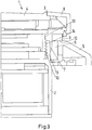
- Fig. 3
- is a section through the unit in part.
- A
unit 1 as shown inFig. 1 is used to set and display parameters in a heating or cooling system. Theunit 1 comprises asocket 2 which is also termed as "first part". Thesocket 2 is designed to be fixedly mounted in a wall of a room or a building. Thesocket 2 comprises parts like one or more sensors, electrical connections, switches and so on. These parts should not directly be actuated by a person. - Furthermore, the
unit 2 comprises asecond part 3. Thesecond part 3 comprises display and/or operating means 4 in the form of a touch screen and/or buttons, switches, LEDs or the like. - A
frame 5 is provided to be mounted between thesocket 2 and thesecond part 3. Thisframe 5 comprises anopening 6. Thisopening 6 is larger than a connectingpart 7 of thesecond part 3. This connectingpart 7 is used to connect thesecond part 3 and thesocket 2. To this end the connectingpart 7 is inserted through theopening 6. The second part together with theframe 5 can then be mounted on thesocket 2. Another possibility is to first position the frame on the socket 2 (or a wall in which thesocket 2 is mounted) and to mount thesecond part 3 thereafter. -
Fig. 2 shows theunit 1 in a mounted state. However, thesocket 2 is not built in a wall. - Since the
opening 6 of theframe 5 is larger than the connecting part of the second part 3 aunit 1 can be used with a lot ofdifferent frames 5 thus making it possible to adapt the unit optically to different surroundings. - Since there is no positive locking connection between the
frame 5 and the connectingpart 7 of thesecond part 3 other means for holding theframe 5 in position are provided. - The
second part 3 comprises acollar 8 which is larger than theopening 6 of theframe 5. Therefore, thecollar 8 covers more than theopening 6 of theframe 5. - A
compressible material 9 is arranged between thesecond part 3 and theframe 5, more precisely between thecollar 8 and theframe 5. When thesecond part 3 is mounted on thesocket 2 thecompressible material 9 is pressed against theframe 5 by means of thecollar 8 with a force generating a friction force between theframe 5 and thecollar 8. The friction force is greater than twice of the force created by the weight of theframe 5. This is sufficient to hold theframe 5 in position even if the frame is mounted moveable in vertical direction, as shown inFig. 2 . However, it is possible to adjust the position of theframe 5 even after mounting. - The
compressible material 9 is in the form of a ring, wherein thering 9 follows the form of theopening 6. Therefore, it can be made sure that thecompressible material 9 is always in contact with aninner edge 10 of theframe 5 surrounding theopening 6. - As can be seen in
Fig. 3 thesocket 2 comprises afirst member 11 of a catch mechanism, saidfirst member 11 having a number of teeth 12. Thesecond part 3 comprises asecond member 13 of the catch mechanism, wherein saidsecond member 13 comprises a number of teeth 14. The pitch of the teeth 12, 14 is the same. At least one of themembers second number 13 of thesecond part 3 catches behind a tooth 12 of thefirst member 11 of the catch mechanism. - The two
members compressible material 9 in an uncompressed state. This has the effect that asecond part 3 can be pushed onto thesocket 2 until thecompressible material 9 rests against thecollar 8 and against theframe 5 without being compressed or just slightly being compressed. In order to achieve a sufficient compression of thecompressible material 9 thesecond part 3 is moved one locking position further. Since the distance between two adjacent locking positions is smaller than a thickness of the compressible material in an uncompressed state this leads to the fact that thecompressible material 9 is sufficiently compressed but not compressed too strong. Therefore, mounting errors can hardly occur. - Since the
collar 8 has to be larger than theopening 6 the display and/or operating means can be made larger as well. In an embodiment not shown in the drawing the display and/or operating means can be made even larger than theopening 6.
Claims (5)
- A unit (1) comprising a socket (2) forming a first part, a second part (3) mountable on the socket (2), a frame (5) between the socket (2) and the second part (3), said frame (5) having an opening (6) surrounding a connecting section (7) of the two parts (2, 3), wherein said opening (6) is larger than said connecting section (7), said first part (2) and said second part (3) are connected by means of a catch mechanism (11-14), said catch mechanism (7) having at least two locking positions, characterized in that said second part (3) comprises a collar (8) being larger than said opening (6), wherein a compressible material (9) is arranged between said collar (8) and said frame (5), said compressible material (9) being pressed against said frame (5) by means of said collar (8), a distance between two adjacent locking positions being smaller than a thickness of the compressible material (9) in an uncompressed state.
- The unit according to claim 1, characterized in that said collar (8) is pressed against said compressible material (9) with a force generating a friction force between said frame (5) and said collar (8), said friction force being greater than twice of the force created by the weight of the frame(5).
- The unit according to claim 1 or 2, characterized in that said compressible material (9) is in the form of a ring, said ring following the form of the opening (6).
- The unit according to any of claims 1 to 3, characterized in that said second part (3) comprises display and/or operating means (4) in an area on a side parallel to said opening (6), said area being larger than said opening (6).
- The unit according to claim 4, characterized in that said display and/or operating means (4) comprise a touch screen.
Priority Applications (3)
| Application Number | Priority Date | Filing Date | Title |
|---|---|---|---|
| EP11008774.9A EP2589890B1 (en) | 2011-11-03 | 2011-11-03 | A unit for a system |
| RU2012146467/12A RU2530839C2 (en) | 2011-11-03 | 2012-11-01 | Block for system |
| CN201210432281.9A CN103096662B (en) | 2011-11-03 | 2012-11-02 | Unit for system |
Applications Claiming Priority (1)
| Application Number | Priority Date | Filing Date | Title |
|---|---|---|---|
| EP11008774.9A EP2589890B1 (en) | 2011-11-03 | 2011-11-03 | A unit for a system |
Publications (2)
| Publication Number | Publication Date |
|---|---|
| EP2589890A1 EP2589890A1 (en) | 2013-05-08 |
| EP2589890B1 true EP2589890B1 (en) | 2019-04-10 |
Family
ID=45002504
Family Applications (1)
| Application Number | Title | Priority Date | Filing Date |
|---|---|---|---|
| EP11008774.9A Active EP2589890B1 (en) | 2011-11-03 | 2011-11-03 | A unit for a system |
Country Status (3)
| Country | Link |
|---|---|
| EP (1) | EP2589890B1 (en) |
| CN (1) | CN103096662B (en) |
| RU (1) | RU2530839C2 (en) |
Families Citing this family (2)
| Publication number | Priority date | Publication date | Assignee | Title |
|---|---|---|---|---|
| DE102014103687B3 (en) * | 2014-03-18 | 2015-07-23 | Gira Giersiepen Gmbh & Co. Kg | Electrical or electronic installation device |
| DE102014104383A1 (en) * | 2014-03-28 | 2015-10-01 | Berker Gmbh & Co. Kg | Wall-integrated display device |
Family Cites Families (5)
| Publication number | Priority date | Publication date | Assignee | Title |
|---|---|---|---|---|
| DE102004051928B4 (en) * | 2004-10-25 | 2010-10-28 | Ifm Electronic Gmbh | Fastening element for a housing and fastening system consisting of a housing, a mounting plate and a fastening element |
| DE102005016082B4 (en) * | 2005-04-08 | 2008-10-02 | Abb Ag | Flush installation device with device insert and support ring |
| ATE534177T1 (en) * | 2008-03-31 | 2011-12-15 | Schneider Electric Ind Sas | MOUNTING FRAME |
| US8802981B2 (en) * | 2008-10-27 | 2014-08-12 | Lennox Industries Inc. | Flush wall mount thermostat and in-set mounting plate for a heating, ventilation and air conditioning system |
| CN101604082A (en) * | 2009-07-17 | 2009-12-16 | 友达光电股份有限公司 | Display device with panel positioning function and manufacturing method thereof |
-
2011
- 2011-11-03 EP EP11008774.9A patent/EP2589890B1/en active Active
-
2012
- 2012-11-01 RU RU2012146467/12A patent/RU2530839C2/en active
- 2012-11-02 CN CN201210432281.9A patent/CN103096662B/en active Active
Non-Patent Citations (1)
| Title |
|---|
| None * |
Also Published As
| Publication number | Publication date |
|---|---|
| CN103096662B (en) | 2018-02-27 |
| EP2589890A1 (en) | 2013-05-08 |
| RU2530839C2 (en) | 2014-10-20 |
| CN103096662A (en) | 2013-05-08 |
| RU2012146467A (en) | 2014-05-10 |
Similar Documents
| Publication | Publication Date | Title |
|---|---|---|
| KR101249495B1 (en) | Display panel unit fixing device | |
| CN106463926B (en) | Safely assembled electrical equipment | |
| JP7253105B1 (en) | Mounting device with fastener receiving structure | |
| US20160187003A1 (en) | Backguard panel with integrated proud glass control mount | |
| EP2982910B1 (en) | Indoor unit of air-conditioning apparatus | |
| KR101680969B1 (en) | Control assembly and cooking apparatus having control assembly | |
| EP2589890A1 (en) | A unit for a system | |
| WO2003005107A3 (en) | Housing for the remote control of an electrical installation | |
| US20180363922A1 (en) | A household appliance control unit | |
| EP2360308B1 (en) | A control panel for a household appliance | |
| RU2770907C2 (en) | Cover plate and group of parts for wall-mounted modular electrical appliances | |
| WO2008081321A1 (en) | Support panel for video door entry stations with concealed fixing | |
| CN103095315A (en) | Wireless receiver | |
| RU2754816C2 (en) | Overhead element and overhead plate for wall-mounted modular electrical appliances | |
| EP2375204A2 (en) | Display panel assembly for electrical appliances | |
| EP3924990B1 (en) | Modular electronic device for electrical and/or home automation systems | |
| JP2009236217A (en) | Seal member | |
| JP6077429B2 (en) | Hot air heater | |
| CN106352521B (en) | Air conditioner air guide device with moving part, control method and air conditioner | |
| KR101898563B1 (en) | Video Door Phone with Adjustable Angle of Camera | |
| CN114830477A (en) | Two-part electrical housing | |
| JP2005183162A (en) | Operating device | |
| KR20050062045A (en) | A domestic appliance | |
| CN223242201U (en) | A control component and a water outlet device | |
| WO2007037948A3 (en) | Door assembly having a flexible detector member and an associated method |
Legal Events
| Date | Code | Title | Description |
|---|---|---|---|
| PUAI | Public reference made under article 153(3) epc to a published international application that has entered the european phase |
Free format text: ORIGINAL CODE: 0009012 |
|
| AK | Designated contracting states |
Kind code of ref document: A1 Designated state(s): AL AT BE BG CH CY CZ DE DK EE ES FI FR GB GR HR HU IE IS IT LI LT LU LV MC MK MT NL NO PL PT RO RS SE SI SK SM TR |
|
| AX | Request for extension of the european patent |
Extension state: BA ME |
|
| 17P | Request for examination filed |
Effective date: 20131018 |
|
| RBV | Designated contracting states (corrected) |
Designated state(s): AL AT BE BG CH CY CZ DE DK EE ES FI FR GB GR HR HU IE IS IT LI LT LU LV MC MK MT NL NO PL PT RO RS SE SI SK SM TR |
|
| REG | Reference to a national code |
Ref country code: DE Ref legal event code: R079 Ref document number: 602011057877 Country of ref document: DE Free format text: PREVIOUS MAIN CLASS: F24F0011000000 Ipc: F24F0011300000 |
|
| GRAP | Despatch of communication of intention to grant a patent |
Free format text: ORIGINAL CODE: EPIDOSNIGR1 |
|
| STAA | Information on the status of an ep patent application or granted ep patent |
Free format text: STATUS: GRANT OF PATENT IS INTENDED |
|
| RIC1 | Information provided on ipc code assigned before grant |
Ipc: F24F 11/30 20130508AFI20181010BHEP |
|
| INTG | Intention to grant announced |
Effective date: 20181102 |
|
| RIC1 | Information provided on ipc code assigned before grant |
Ipc: F24F 11/30 20180101AFI20181010BHEP |
|
| RIC1 | Information provided on ipc code assigned before grant |
Ipc: F24F 11/30 20180101AFI20181010BHEP |
|
| GRAS | Grant fee paid |
Free format text: ORIGINAL CODE: EPIDOSNIGR3 |
|
| GRAA | (expected) grant |
Free format text: ORIGINAL CODE: 0009210 |
|
| STAA | Information on the status of an ep patent application or granted ep patent |
Free format text: STATUS: THE PATENT HAS BEEN GRANTED |
|
| AK | Designated contracting states |
Kind code of ref document: B1 Designated state(s): AL AT BE BG CH CY CZ DE DK EE ES FI FR GB GR HR HU IE IS IT LI LT LU LV MC MK MT NL NO PL PT RO RS SE SI SK SM TR |
|
| REG | Reference to a national code |
Ref country code: GB Ref legal event code: FG4D |
|
| REG | Reference to a national code |
Ref country code: CH Ref legal event code: EP Ref country code: AT Ref legal event code: REF Ref document number: 1119219 Country of ref document: AT Kind code of ref document: T Effective date: 20190415 |
|
| REG | Reference to a national code |
Ref country code: IE Ref legal event code: FG4D |
|
| REG | Reference to a national code |
Ref country code: DE Ref legal event code: R096 Ref document number: 602011057877 Country of ref document: DE |
|
| REG | Reference to a national code |
Ref country code: NL Ref legal event code: MP Effective date: 20190410 |
|
| REG | Reference to a national code |
Ref country code: LT Ref legal event code: MG4D |
|
| REG | Reference to a national code |
Ref country code: AT Ref legal event code: MK05 Ref document number: 1119219 Country of ref document: AT Kind code of ref document: T Effective date: 20190410 |
|
| PG25 | Lapsed in a contracting state [announced via postgrant information from national office to epo] |
Ref country code: NL Free format text: LAPSE BECAUSE OF FAILURE TO SUBMIT A TRANSLATION OF THE DESCRIPTION OR TO PAY THE FEE WITHIN THE PRESCRIBED TIME-LIMIT Effective date: 20190410 |
|
| PG25 | Lapsed in a contracting state [announced via postgrant information from national office to epo] |
Ref country code: FI Free format text: LAPSE BECAUSE OF FAILURE TO SUBMIT A TRANSLATION OF THE DESCRIPTION OR TO PAY THE FEE WITHIN THE PRESCRIBED TIME-LIMIT Effective date: 20190410 Ref country code: PT Free format text: LAPSE BECAUSE OF FAILURE TO SUBMIT A TRANSLATION OF THE DESCRIPTION OR TO PAY THE FEE WITHIN THE PRESCRIBED TIME-LIMIT Effective date: 20190910 Ref country code: NO Free format text: LAPSE BECAUSE OF FAILURE TO SUBMIT A TRANSLATION OF THE DESCRIPTION OR TO PAY THE FEE WITHIN THE PRESCRIBED TIME-LIMIT Effective date: 20190710 Ref country code: AL Free format text: LAPSE BECAUSE OF FAILURE TO SUBMIT A TRANSLATION OF THE DESCRIPTION OR TO PAY THE FEE WITHIN THE PRESCRIBED TIME-LIMIT Effective date: 20190410 Ref country code: SE Free format text: LAPSE BECAUSE OF FAILURE TO SUBMIT A TRANSLATION OF THE DESCRIPTION OR TO PAY THE FEE WITHIN THE PRESCRIBED TIME-LIMIT Effective date: 20190410 Ref country code: LT Free format text: LAPSE BECAUSE OF FAILURE TO SUBMIT A TRANSLATION OF THE DESCRIPTION OR TO PAY THE FEE WITHIN THE PRESCRIBED TIME-LIMIT Effective date: 20190410 Ref country code: HR Free format text: LAPSE BECAUSE OF FAILURE TO SUBMIT A TRANSLATION OF THE DESCRIPTION OR TO PAY THE FEE WITHIN THE PRESCRIBED TIME-LIMIT Effective date: 20190410 Ref country code: ES Free format text: LAPSE BECAUSE OF FAILURE TO SUBMIT A TRANSLATION OF THE DESCRIPTION OR TO PAY THE FEE WITHIN THE PRESCRIBED TIME-LIMIT Effective date: 20190410 |
|
| PG25 | Lapsed in a contracting state [announced via postgrant information from national office to epo] |
Ref country code: RS Free format text: LAPSE BECAUSE OF FAILURE TO SUBMIT A TRANSLATION OF THE DESCRIPTION OR TO PAY THE FEE WITHIN THE PRESCRIBED TIME-LIMIT Effective date: 20190410 Ref country code: BG Free format text: LAPSE BECAUSE OF FAILURE TO SUBMIT A TRANSLATION OF THE DESCRIPTION OR TO PAY THE FEE WITHIN THE PRESCRIBED TIME-LIMIT Effective date: 20190710 Ref country code: PL Free format text: LAPSE BECAUSE OF FAILURE TO SUBMIT A TRANSLATION OF THE DESCRIPTION OR TO PAY THE FEE WITHIN THE PRESCRIBED TIME-LIMIT Effective date: 20190410 Ref country code: LV Free format text: LAPSE BECAUSE OF FAILURE TO SUBMIT A TRANSLATION OF THE DESCRIPTION OR TO PAY THE FEE WITHIN THE PRESCRIBED TIME-LIMIT Effective date: 20190410 Ref country code: GR Free format text: LAPSE BECAUSE OF FAILURE TO SUBMIT A TRANSLATION OF THE DESCRIPTION OR TO PAY THE FEE WITHIN THE PRESCRIBED TIME-LIMIT Effective date: 20190711 |
|
| PG25 | Lapsed in a contracting state [announced via postgrant information from national office to epo] |
Ref country code: AT Free format text: LAPSE BECAUSE OF FAILURE TO SUBMIT A TRANSLATION OF THE DESCRIPTION OR TO PAY THE FEE WITHIN THE PRESCRIBED TIME-LIMIT Effective date: 20190410 Ref country code: IS Free format text: LAPSE BECAUSE OF FAILURE TO SUBMIT A TRANSLATION OF THE DESCRIPTION OR TO PAY THE FEE WITHIN THE PRESCRIBED TIME-LIMIT Effective date: 20190810 |
|
| REG | Reference to a national code |
Ref country code: DE Ref legal event code: R097 Ref document number: 602011057877 Country of ref document: DE |
|
| PG25 | Lapsed in a contracting state [announced via postgrant information from national office to epo] |
Ref country code: SK Free format text: LAPSE BECAUSE OF FAILURE TO SUBMIT A TRANSLATION OF THE DESCRIPTION OR TO PAY THE FEE WITHIN THE PRESCRIBED TIME-LIMIT Effective date: 20190410 Ref country code: RO Free format text: LAPSE BECAUSE OF FAILURE TO SUBMIT A TRANSLATION OF THE DESCRIPTION OR TO PAY THE FEE WITHIN THE PRESCRIBED TIME-LIMIT Effective date: 20190410 Ref country code: CZ Free format text: LAPSE BECAUSE OF FAILURE TO SUBMIT A TRANSLATION OF THE DESCRIPTION OR TO PAY THE FEE WITHIN THE PRESCRIBED TIME-LIMIT Effective date: 20190410 Ref country code: EE Free format text: LAPSE BECAUSE OF FAILURE TO SUBMIT A TRANSLATION OF THE DESCRIPTION OR TO PAY THE FEE WITHIN THE PRESCRIBED TIME-LIMIT Effective date: 20190410 Ref country code: DK Free format text: LAPSE BECAUSE OF FAILURE TO SUBMIT A TRANSLATION OF THE DESCRIPTION OR TO PAY THE FEE WITHIN THE PRESCRIBED TIME-LIMIT Effective date: 20190410 |
|
| PLBE | No opposition filed within time limit |
Free format text: ORIGINAL CODE: 0009261 |
|
| STAA | Information on the status of an ep patent application or granted ep patent |
Free format text: STATUS: NO OPPOSITION FILED WITHIN TIME LIMIT |
|
| PG25 | Lapsed in a contracting state [announced via postgrant information from national office to epo] |
Ref country code: IT Free format text: LAPSE BECAUSE OF FAILURE TO SUBMIT A TRANSLATION OF THE DESCRIPTION OR TO PAY THE FEE WITHIN THE PRESCRIBED TIME-LIMIT Effective date: 20190410 Ref country code: SM Free format text: LAPSE BECAUSE OF FAILURE TO SUBMIT A TRANSLATION OF THE DESCRIPTION OR TO PAY THE FEE WITHIN THE PRESCRIBED TIME-LIMIT Effective date: 20190410 |
|
| 26N | No opposition filed |
Effective date: 20200113 |
|
| PG25 | Lapsed in a contracting state [announced via postgrant information from national office to epo] |
Ref country code: TR Free format text: LAPSE BECAUSE OF FAILURE TO SUBMIT A TRANSLATION OF THE DESCRIPTION OR TO PAY THE FEE WITHIN THE PRESCRIBED TIME-LIMIT Effective date: 20190410 |
|
| PG25 | Lapsed in a contracting state [announced via postgrant information from national office to epo] |
Ref country code: SI Free format text: LAPSE BECAUSE OF FAILURE TO SUBMIT A TRANSLATION OF THE DESCRIPTION OR TO PAY THE FEE WITHIN THE PRESCRIBED TIME-LIMIT Effective date: 20190410 |
|
| REG | Reference to a national code |
Ref country code: CH Ref legal event code: PL |
|
| PG25 | Lapsed in a contracting state [announced via postgrant information from national office to epo] |
Ref country code: LU Free format text: LAPSE BECAUSE OF NON-PAYMENT OF DUE FEES Effective date: 20191103 Ref country code: CH Free format text: LAPSE BECAUSE OF NON-PAYMENT OF DUE FEES Effective date: 20191130 Ref country code: LI Free format text: LAPSE BECAUSE OF NON-PAYMENT OF DUE FEES Effective date: 20191130 Ref country code: MC Free format text: LAPSE BECAUSE OF FAILURE TO SUBMIT A TRANSLATION OF THE DESCRIPTION OR TO PAY THE FEE WITHIN THE PRESCRIBED TIME-LIMIT Effective date: 20190410 |
|
| REG | Reference to a national code |
Ref country code: BE Ref legal event code: MM Effective date: 20191130 |
|
| PG25 | Lapsed in a contracting state [announced via postgrant information from national office to epo] |
Ref country code: IE Free format text: LAPSE BECAUSE OF NON-PAYMENT OF DUE FEES Effective date: 20191103 |
|
| PG25 | Lapsed in a contracting state [announced via postgrant information from national office to epo] |
Ref country code: BE Free format text: LAPSE BECAUSE OF NON-PAYMENT OF DUE FEES Effective date: 20191130 |
|
| PG25 | Lapsed in a contracting state [announced via postgrant information from national office to epo] |
Ref country code: CY Free format text: LAPSE BECAUSE OF FAILURE TO SUBMIT A TRANSLATION OF THE DESCRIPTION OR TO PAY THE FEE WITHIN THE PRESCRIBED TIME-LIMIT Effective date: 20190410 |
|
| PG25 | Lapsed in a contracting state [announced via postgrant information from national office to epo] |
Ref country code: MT Free format text: LAPSE BECAUSE OF FAILURE TO SUBMIT A TRANSLATION OF THE DESCRIPTION OR TO PAY THE FEE WITHIN THE PRESCRIBED TIME-LIMIT Effective date: 20190410 Ref country code: HU Free format text: LAPSE BECAUSE OF FAILURE TO SUBMIT A TRANSLATION OF THE DESCRIPTION OR TO PAY THE FEE WITHIN THE PRESCRIBED TIME-LIMIT; INVALID AB INITIO Effective date: 20111103 |
|
| PG25 | Lapsed in a contracting state [announced via postgrant information from national office to epo] |
Ref country code: MK Free format text: LAPSE BECAUSE OF FAILURE TO SUBMIT A TRANSLATION OF THE DESCRIPTION OR TO PAY THE FEE WITHIN THE PRESCRIBED TIME-LIMIT Effective date: 20190410 |
|
| P01 | Opt-out of the competence of the unified patent court (upc) registered |
Effective date: 20230617 |
|
| PGFP | Annual fee paid to national office [announced via postgrant information from national office to epo] |
Ref country code: DE Payment date: 20251007 Year of fee payment: 15 |
|
| PGFP | Annual fee paid to national office [announced via postgrant information from national office to epo] |
Ref country code: GB Payment date: 20251016 Year of fee payment: 15 |
|
| PGFP | Annual fee paid to national office [announced via postgrant information from national office to epo] |
Ref country code: FR Payment date: 20251023 Year of fee payment: 15 |