EP2589825A1 - Fastening method, fastening element and fastening arrangement - Google Patents
Fastening method, fastening element and fastening arrangement Download PDFInfo
- Publication number
- EP2589825A1 EP2589825A1 EP20120182425 EP12182425A EP2589825A1 EP 2589825 A1 EP2589825 A1 EP 2589825A1 EP 20120182425 EP20120182425 EP 20120182425 EP 12182425 A EP12182425 A EP 12182425A EP 2589825 A1 EP2589825 A1 EP 2589825A1
- Authority
- EP
- European Patent Office
- Prior art keywords
- fastening
- structural element
- stud
- fastening element
- secured
- Prior art date
- Legal status (The legal status is an assumption and is not a legal conclusion. Google has not performed a legal analysis and makes no representation as to the accuracy of the status listed.)
- Granted
Links
Images

Classifications
-
- F—MECHANICAL ENGINEERING; LIGHTING; HEATING; WEAPONS; BLASTING
- F16—ENGINEERING ELEMENTS AND UNITS; GENERAL MEASURES FOR PRODUCING AND MAINTAINING EFFECTIVE FUNCTIONING OF MACHINES OR INSTALLATIONS; THERMAL INSULATION IN GENERAL
- F16B—DEVICES FOR FASTENING OR SECURING CONSTRUCTIONAL ELEMENTS OR MACHINE PARTS TOGETHER, e.g. NAILS, BOLTS, CIRCLIPS, CLAMPS, CLIPS OR WEDGES; JOINTS OR JOINTING
- F16B21/00—Means for preventing relative axial movement of a pin, spigot, shaft or the like and a member surrounding it; Stud-and-socket releasable fastenings
- F16B21/02—Releasable fastening devices locking by rotation
Definitions
- the present invention relates to a method for fastening a structural element, in particular a strip arrangement, to a workpiece, in particular to a body portion, with the steps of securing a stud to the workpiece, of premounting a fastening element on the structural element, the fastening element having a stud receptacle, and of pushing the fastening element in a longitudinal direction onto the stud.
- the present invention relates, furthermore, to a fastening element which is suitable particularly for carrying out this method, with a hollow basic body, the inner space of which has a stud receptacle for the axial reception of a stud and on the outside of which a fastening portion for axially securing a structural element is formed.
- the present invention relates to a fastening arrangement with a stud which is joined to a surface of a workpiece and with a fastening element which has a stud receptacle and a fastening portion, the fastening element being pushed onto the stud, and a structural element being secured axially to the fastening element.
- Fastening systems of this type are known, in particular, in the field of motor vehicle body construction.
- it is known to join studs to workpieces, such as body panels. This may take place, for example, by what is known as stud welding.
- it is also known to glue studs to workpieces or, if the stud and workpiece are formed from a thermoplastic, to carry out the joining operation by means of a thermoplastic welding method.
- Fastening elements which have a stud receptacle, can then be secured to such studs which usually project perpendicularly with respect to a surface of the workpiece.
- the fastening element which is produced, for example, as a clip from a plastic, is pushed onto the stud, so that securing to the stud takes place in a radial direction and, by suitable securing means, in an axial direction.
- Such a fastening element may be, for example, electrical cable bunches, trim parts, dashboard parts, etc.
- the axial securing of the fastening element to the stud usually takes place in that, for example, one or more blocking elements engage radially elastically into the thread flight.
- the different fixing height may be a disadvantage. This applies particularly when the strip arrangements are arranged in a visible region.
- an object of the invention is to specify an improved method for fastening a structural element to a workpiece, an improved fastening element and an improved fastening arrangement.
- This object is achieved, on the one hand, by means of a method for fastening a structural element, in particular a strip arrangement, to a workpiece, in particular to a body portion, with the steps of securing a stud to the workpiece, of premounting a fastening element on the structural element, the fastening element having a stud receptacle, of pushing the fastening element in a longitudinal direction onto the stud and of subsequently moving the structural element in a direction of movement, a driver portion of the structural element engaging on the fastening element in such a way that the fastening element is rotated about the longitudinal axis.
- a fastening element in particular for carrying out the abovementioned method, with a hollow basic body, the inner space of which has a stud receptacle for the axial reception of a stud and on the outside of which a fastening portion for axially securing a structural element is formed, there being formed, furthermore, on the basic body a boss portion which is designed, during a movement of the axially secured structural element transversely with respect to the axial direction, to be driven by a driver portion of the structural element, so that the fastening element rotates.
- the above object is achieved by means of a fastening arrangement with a stud which is joined to a surface of a workpiece, and with a fastening element which has a stud receptacle and a fastening portion, the fastening element being pushed onto the stud, and a structural element being secured axially to the fastening element, the fastening element being a fastening element according to the invention and/or the fastening arrangement being produced by means of the method according to the invention.
- the basic idea of the fastening system according to the invention is to secure the structural element to the stud by means of the fastening element and subsequently to move the said structural element in a direction transverse with respect to the axial direction, the fastening element being rotated about the longitudinal axis.
- the fastening element, together with the structural element secured axially on it is drawn, for example, in a direction towards the workpiece (for example, as a result of the engagement of at least one blocking element on a thread flight).
- the structural element is always positioned ideally with respect to the workpiece, in particular in the same height position.
- the structural element is generally secured to the workpiece under certain axial prestress.
- the movement step involves displacement of the structural element in a direction transverse with respect to the longitudinal direction.
- the movement step involves rotation of the structural element.
- a displacement step can usually be carried out more simply.
- such a displacement step is preferably active simultaneously for a plurality of fastening arrangements, by means of which an elongate structural element, such as a strip arrangement, is fastened to a workpiece.
- a strip arrangement having a plurality of fastening elements secured to it can first be pressed onto a corresponding plurality of studs previously secured to the workpiece.
- the fastening elements are then in each case rotated about their longitudinal axis and consequently drawn preferably in a direction towards the workpiece.
- the stud has in this case at least one thread flight, the stud receptacle of the fastening element having at least one blocking element engaging on the thread flight, so that, during the movement step, the fastening element, together with the structural element secured to it, is moved in the direction of the longitudinal axis.
- the fastening element is secured to the structural element by latching during the premounting step, the latching connection being released during the movement step.
- the situation where, after the premounting step, the fastening element unintentionally comes loose again from the structural element can thereby be prevented.
- the individual fastening elements can consequently be premounted securely in succession, without running the risk that a previously premounted fastening element comes loose again. Since the latching connection is released again during the movement step, greater degrees of freedom in the relative end position between the structural element and the fastening element are obtained.
- the fastening element prefferably secured to the structural element in a floating manner in at least one direction transverse with respect to the longitudinal direction.
- the latching connection may in this case be at least partially released even while the fastening element is being pushed in the longitudinal direction onto the stud, if there are relatively large tolerances in the spacings between the studs or in their axial alignment. Since there is no longer any risk at this time that the fastening elements come loose from the structural element again, what can also be achieved thereby is that relatively large tolerances can be compensated.
- the boss portion has at least one boss extending radially from the basic body.
- Such a boss may be driven, for example, by means of a driver portion, if the latter is provided on a strip arrangement and extends in a direction transverse with respect to the displacement direction.
- At least one latching nose extends radially from the basic body, the latching nose being deflectable elastically in the axial direction and being designed to engage into a latching connection of the structural element when the structural element is premounted on the fastening element.
- boss and the latching nose by means of a single nose extending radially. It is especially preferable, however, if the boss and the latching nose extend separately from the basic body. As a result, on the one hand, a more reliable latching connection in the premounting position can be achieved. On the other hand, jamming can thereby be avoided when a driver portion of the structural element engages on the boss in order to rotate the fastening element.
- the structural element may be fixed axially to the fastening element in various ways.
- the fastening portion has a first flange portion and a second flange portion which is spaced axially from the first flange portion.
- the fastening element can, for example, be pushed on between two parallel-extending webs of the structural element, the webs engaging between the first and the second flange portion.
- the webs may in this case preferably extend parallel to the displacement direction.
- a driver portion may be formed on one or on both webs.
- the second flange portion is aligned in the axial direction with a boss portion and/or with a latching nose.
- the fastening element can be produced by means of a relatively simple injection-moulding die. Furthermore, it is possible to provide a latching device, for example, on a web of the structural element, so that it is possible for the latching connection to be set up in a simple way when the fastening element is being pushed onto the webs.
- the second flange portion extends in the circumferential direction over an angular range of less than 180°.
- the second flange portion extends in the circumferential direction over only an angular range of less than 180°, it can thereby be ensured that a driver portion of a structural element can engage both on one boss and on the other radially opposite boss, without being impeded by the second flange portion.
- the second flange portion preferably has an axial fixing function in the premounting position only. As soon as the structural element is secured to the stud via the fastening element and is suppressed under prestress against the workpiece, the second flange portion usually no longer has to absorb any forces.
- the stud receptacle has at least one blocking element deflectable elastically in the radial direction, such as a blocking nose or the like, which can engage, for example, into a thread flight of a threaded stud.
- At least two, in particular three blocking elements are provided, distributed in the circumferential direction, in the stud receptacle.
- the fastening arrangement is no longer visible when the trim element is secured to the structural element.
- the fastening of the structural element via the fastening element is adapted in terms of height and a pull towards the workpiece is exerted. Mounting inaccuracies in terms of height can thereby be compensated.
- the structural element is in this case drawn towards the workpiece and therefore, after the step of moving the structural element, is seated so as to be free of rattling with respect to the workpiece.
- a first embodiment of a fastening arrangement is designated in general by 10.
- the fastening arrangement 10 contains a workpiece 12, such as, for example, a body panel, to the surface of which a stud 14 is joined, for example by stud welding, by stud gluing or by thermoplastic welding.
- the surface of the workpiece 12 extends in a plane which is spanned by coordinates x, y.
- the stud 14 extends perpendicularly thereto in a direction z.
- the stud is preferably joined to the surface of the workpiece 12 by means of a flange portion and has a shank portion.
- the fastening arrangement 10 has, furthermore, a fastening element 16.
- the fastening element 16 is designed as a hollow one-piece component (preferably made from plastic) and has a stud receptacle 18 oriented in the z-direction.
- a plurality of blocking elements 20 are formed on the inner circumference of the stud receptacle 18 and are preferably designed to be deflectable in the radial direction.
- a thread with at least one thread flight 22, which is illustrated diagrammatically in Fig. 1 , is preferably formed on the shank of the stud 14.
- the fastening element 16 is pushed onto the stud 14 in such a way that the stud 14 is received in the stud receptacle 18 and the blocking elements 20 are pressed elastically radially into the thread flight 22, in such a way that the fastening element 16 is secured axially to the stud 14.
- the blocking elements 20 may be arranged, distributed over the circumference, at the same axial height or at a different axial height, as illustrated diagrammatically in Fig. 1 .
- the fastening arrangement 10 has, furthermore, a structural element 26 which is secured in the axial direction to the fastening element 16.
- the structural element 26 has a plurality of fastening fingers 28 which are arranged, distributed on the circumference, and which engage into respective radial recesses 30 on the outer circumference of the fastening element 16.
- the fastening fingers 28 may likewise be deflectable elastically radially.
- the fastening element 16 is first premounted on the structural element 26 in that the fastening element 16 is secured to the structural element 26 such that the fastening fingers 28 engage into the respective radial recesses 30 of the fastening element 16.
- the premounted arrangement consisting of the fastening element 16 and of the structural element 26 is pressed onto the stud 14 in the axial direction (z-direction), the blocking elements 20 engaging into the thread flight 22.
- a movement step 32 takes place, in which, in the present embodiment, the structural element 26 is rotated about the longitudinal axis.
- the fastening element 16 is driven, as shown at 34, so that the fastening element 16 is likewise rotated about the longitudinal axis. Since the blocking elements 20 engage on the thread flight 22, the fastening element 16 is consequently drawn in a direction towards the surface of the workpiece 12, as shown by an axial movement direction 36.
- the structural element 26 is in this case driven in the axial direction and can thus be pressed as far as it will go onto the surface of the workpiece 12, engagement between the blocking elements 20 and the thread flight 22 generating a certain axial prestress. The structural element 26 can thereby be secured, free of rattling, to the workpiece 12.
- a fastening element 16 of an alternative embodiment is shown in Fig. 2 to 7 .
- the fastening element 16 of Fig. 2 to 7 is designed, in particular, for producing a fastening arrangement, such as is shown Fig. 8 to 10 .
- the embodiment, shown in Fig. 2 to 10 , of a fastening arrangement generally corresponds in terms of set-up and functioning to the fastening arrangement of Fig. 1 . Identical elements are therefore identified by the same reference symbols. Essentially, the differences are explained below.
- the fastening element 16 of Fig. 2 to 7 has a hollow-cylindrical basic body 40, on the outer circumference of which a first flange portion 42 and a second flange portion 44 are formed.
- the second flange portion 44 extends over an angular range 46 of less than 180°, in the present case of about 130°.
- the flange portions 42, 44 are spaced axially from one another, as shown at 48.
- bosses 54 extend from the basic body 40, specifically in such a way that they extend approximately parallel to the latching noses 50.
- the bosses 54 are spaced in the circumferential direction from the latching noses 50.
- the latching noses 50 have in each case on their underside (on the side facing the first flange portion 42) latching projections 52 which project into the region of the spacing 48.
- the latching noses 50 are in this case connected to the basic body 40 in such a way that they are deflectable elastically to a limited extent in the axial direction.
- the inner space of the basic body 40 defines a stud receptacle 56.
- the stud receptacle 56 has in this case three indentations 58 which are spaced from one another in a circumferential direction and in which blocking elements 60 are secured so as to be elastically deflectable radially.
- the blocking elements 60 in this case extend, in the state stretched out non-elastically, obliquely downwards (from the second flange portion 44 towards the first flange portion 42).
- the free ends of the blocking elements 60 in this case define a diameter which is somewhat smaller than an outside diameter 64 of the stud 14 (see Fig. 10 ).
- the stud receptacle 56 has an introduction cone 62 with an introduction diameter 66 which is preferably at least twice as large as the stud diameter 64.
- the fastening element 16 of Fig. 2 to 7 preferably serves for securing a strip arrangement 70 to a workpiece 12.
- the strip arrangement 70 which is shown in Fig. 8 to 10 , has in this case a basic strip 72 to which a trim strip 73 is secured.
- the basic strip 72 has a first web 74 extending in the x-direction and a second web 76 extending parallel thereto.
- the webs 74, 76 are spaced from one another in the y-direction by an amount which is preferably larger than the outside diameter of the basic body 40.
- the webs 74, 76 have in each case a thickness 72 which is equal to or smaller than or equal to the axial spacing 48 between the flange portions 42, 44.
- the fastening element 16 of Fig. 2 to 7 is premounted on the basic strip 72 in such a way that it is pushed in the x-direction between the webs 74, 76, specifically with the two bosses 54 in front.
- a driver portion 80 extending in the y-direction is formed on the top side of the first web 74 and is designed for engaging on the assigned boss 54.
- formed on the top side of at least one of the webs 74, 76 is a latching depression 82, the shape of which is adapted to the latching projections 42 of the latching noses 50.
- the basic strip 72 preferably has a plurality of such webs 74, 76 which are arranged so as to be distributed over the strip axis. In this case, first, a corresponding number of fastening elements 16 are premounted on the respective web arrangements until a position, as shown in Fig. 8 , is reached.
- the introduction cones 62 of the fastening elements 16 face away from the trim strip 72 and face a corresponding number of studs joined to a surface of a workpiece 12.
- the strip arrangement 70 together with the fastening elements 16 premounted on it, is pressed onto the studs 14, as shown in Fig. 10 .
- the blocking elements 60 engage on the outer circumference of the shank of the stud 14 which is preferably designed as a threaded stud with at least one thread flight. Consequently, as shown in Fig. 10 , the strip arrangement 70 is fixed in the axial direction z to the stud 14.
- At least the basic strip 72 is displaced in the x-direction, that is to say transversely with respect to the axis z of the stud 14, as shown at 32 in Fig. 8 .
- the driver portion 8 thereby engages on the assigned boss 54. Since the fastening element 16 is then fixed radially to the stud 14, the fastening element 16 (or all the fastening elements 16) is in this case rotated, as shown at 34 in Fig. 9 . In this case, the latching connection between the latching projections 52 and the latching depressions 82 is released.
- fastening elements 60 are also mounted in a floating manner in the radial direction x with respect to the basic strip 72 (and the trim strip 73 firmly connected to it). Tolerances of the stud spacings and stud alignments can thereby be compensated even in the mounting step.
Landscapes
- Engineering & Computer Science (AREA)
- General Engineering & Computer Science (AREA)
- Mechanical Engineering (AREA)
- Connection Of Plates (AREA)
Abstract
Description
- The present invention relates to a method for fastening a structural element, in particular a strip arrangement, to a workpiece, in particular to a body portion, with the steps of securing a stud to the workpiece, of premounting a fastening element on the structural element, the fastening element having a stud receptacle, and of pushing the fastening element in a longitudinal direction onto the stud.
- The present invention relates, furthermore, to a fastening element which is suitable particularly for carrying out this method, with a hollow basic body, the inner space of which has a stud receptacle for the axial reception of a stud and on the outside of which a fastening portion for axially securing a structural element is formed.
- Finally, the present invention relates to a fastening arrangement with a stud which is joined to a surface of a workpiece and with a fastening element which has a stud receptacle and a fastening portion, the fastening element being pushed onto the stud, and a structural element being secured axially to the fastening element.
- Fastening systems of this type are known, in particular, in the field of motor vehicle body construction. On the one hand, it is known to join studs to workpieces, such as body panels. This may take place, for example, by what is known as stud welding. Alternatively, it is also known to glue studs to workpieces or, if the stud and workpiece are formed from a thermoplastic, to carry out the joining operation by means of a thermoplastic welding method.
- Fastening elements, which have a stud receptacle, can then be secured to such studs which usually project perpendicularly with respect to a surface of the workpiece. For this purpose, the fastening element, which is produced, for example, as a clip from a plastic, is pushed onto the stud, so that securing to the stud takes place in a radial direction and, by suitable securing means, in an axial direction.
- Further components can then be secured to such a fastening element. These may be, for example, electrical cable bunches, trim parts, dashboard parts, etc.
- In fastening arrangements in which the stud has a thread, the axial securing of the fastening element to the stud usually takes place in that, for example, one or more blocking elements engage radially elastically into the thread flight. This presents the problem that the relative rotary position of the stud may be important. This is because the blocking elements engage into the thread flight at different points, depending on the rotary position, and therefore differences may arise with regard to the axial fixing height.
- In order to avoid this, it would be conceivable to fix the rotary position of the stud before it is joined to the workpiece. This means, however, that it is relatively costly to detect the rotary position of the stud in a joining tool.
- Particularly in those fastening elements which are to be secured to a workpiece by means of a plurality of fastening arrangements, such as, for example, strip arrangements, the different fixing height may be a disadvantage. This applies particularly when the strip arrangements are arranged in a visible region.
- Against the above background, an object of the invention is to specify an improved method for fastening a structural element to a workpiece, an improved fastening element and an improved fastening arrangement.
- This object is achieved, on the one hand, by means of a method for fastening a structural element, in particular a strip arrangement, to a workpiece, in particular to a body portion, with the steps of securing a stud to the workpiece, of premounting a fastening element on the structural element, the fastening element having a stud receptacle, of pushing the fastening element in a longitudinal direction onto the stud and of subsequently moving the structural element in a direction of movement, a driver portion of the structural element engaging on the fastening element in such a way that the fastening element is rotated about the longitudinal axis.
- Furthermore, the above object is achieved by means of a fastening element, in particular for carrying out the abovementioned method, with a hollow basic body, the inner space of which has a stud receptacle for the axial reception of a stud and on the outside of which a fastening portion for axially securing a structural element is formed, there being formed, furthermore, on the basic body a boss portion which is designed, during a movement of the axially secured structural element transversely with respect to the axial direction, to be driven by a driver portion of the structural element, so that the fastening element rotates.
- Finally, the above object is achieved by means of a fastening arrangement with a stud which is joined to a surface of a workpiece, and with a fastening element which has a stud receptacle and a fastening portion, the fastening element being pushed onto the stud, and a structural element being secured axially to the fastening element, the fastening element being a fastening element according to the invention and/or the fastening arrangement being produced by means of the method according to the invention.
- The basic idea of the fastening system according to the invention is to secure the structural element to the stud by means of the fastening element and subsequently to move the said structural element in a direction transverse with respect to the axial direction, the fastening element being rotated about the longitudinal axis. What can be achieved thereby is that the fastening element, together with the structural element secured axially on it, is drawn, for example, in a direction towards the workpiece (for example, as a result of the engagement of at least one blocking element on a thread flight). What can ultimately be achieved thereby is that the structural element is always positioned ideally with respect to the workpiece, in particular in the same height position. What can in this case be achieved, furthermore, is that the structural element is generally secured to the workpiece under certain axial prestress.
- The object is thus achieved in full.
- In the fastening method according to the invention, it is advantageous if the movement step involves displacement of the structural element in a direction transverse with respect to the longitudinal direction.
- In general, it is indeed also conceivable that the movement step involves rotation of the structural element. However, a displacement step can usually be carried out more simply. Furthermore, such a displacement step is preferably active simultaneously for a plurality of fastening arrangements, by means of which an elongate structural element, such as a strip arrangement, is fastened to a workpiece.
- In this embodiment, therefore, a strip arrangement having a plurality of fastening elements secured to it can first be pressed onto a corresponding plurality of studs previously secured to the workpiece. As a result of the subsequent displacement movement of the structural element, the fastening elements are then in each case rotated about their longitudinal axis and consequently drawn preferably in a direction towards the workpiece.
- According to a further preferred embodiment, the stud has in this case at least one thread flight, the stud receptacle of the fastening element having at least one blocking element engaging on the thread flight, so that, during the movement step, the fastening element, together with the structural element secured to it, is moved in the direction of the longitudinal axis.
- According to a further preferred embodiment, the fastening element is secured to the structural element by latching during the premounting step, the latching connection being released during the movement step.
- On the one hand, the situation where, after the premounting step, the fastening element unintentionally comes loose again from the structural element can thereby be prevented. Particularly during the premounting of a plurality of fastening elements on a structural element, such as a strip arrangement, the individual fastening elements can consequently be premounted securely in succession, without running the risk that a previously premounted fastening element comes loose again. Since the latching connection is released again during the movement step, greater degrees of freedom in the relative end position between the structural element and the fastening element are obtained.
- According to an especially preferred embodiment, there is in this case provision for the fastening element to be secured to the structural element in a floating manner in at least one direction transverse with respect to the longitudinal direction.
- As a result, particularly in the case of a structural element in the form of a strip arrangement which is secured to a workpiece by means of a plurality of fastening arrangements, relatively large tolerances in the spacings between the studs and/or in the axial alignment of the studs can be compensated.
- Moreover, due to the floating mounting, distortions caused by temperature fluctuations, such as may occur in vehicles, especially in the outside region (visible strips, etc.), can be avoided.
- The latching connection may in this case be at least partially released even while the fastening element is being pushed in the longitudinal direction onto the stud, if there are relatively large tolerances in the spacings between the studs or in their axial alignment. Since there is no longer any risk at this time that the fastening elements come loose from the structural element again, what can also be achieved thereby is that relatively large tolerances can be compensated.
- In the fastening element according to the invention, it is advantageous if the boss portion has at least one boss extending radially from the basic body.
- Such a boss may be driven, for example, by means of a driver portion, if the latter is provided on a strip arrangement and extends in a direction transverse with respect to the displacement direction.
- According to a further preferred embodiment, at least one latching nose extends radially from the basic body, the latching nose being deflectable elastically in the axial direction and being designed to engage into a latching connection of the structural element when the structural element is premounted on the fastening element.
- In general, it is indeed conceivable to implement the boss and the latching nose by means of a single nose extending radially. It is especially preferable, however, if the boss and the latching nose extend separately from the basic body. As a result, on the one hand, a more reliable latching connection in the premounting position can be achieved. On the other hand, jamming can thereby be avoided when a driver portion of the structural element engages on the boss in order to rotate the fastening element.
- The structural element may be fixed axially to the fastening element in various ways.
- It is especially preferable, however, if the fastening portion has a first flange portion and a second flange portion which is spaced axially from the first flange portion.
- In this embodiment, the fastening element can, for example, be pushed on between two parallel-extending webs of the structural element, the webs engaging between the first and the second flange portion. The webs may in this case preferably extend parallel to the displacement direction. A driver portion may be formed on one or on both webs.
- It is especially preferable in this case if the second flange portion is aligned in the axial direction with a boss portion and/or with a latching nose.
- In this embodiment, it is advantageous that the fastening element can be produced by means of a relatively simple injection-moulding die. Furthermore, it is possible to provide a latching device, for example, on a web of the structural element, so that it is possible for the latching connection to be set up in a simple way when the fastening element is being pushed onto the webs.
- It is especially preferable, furthermore, if the second flange portion extends in the circumferential direction over an angular range of less than 180°.
- By virtue of this measure, it is possible to provide on the basic body two radially opposite bosses and/or two radially opposite latching noses, the second flange portion being arranged in the circumferential direction on only one side between the bosses or latching noses.
- It is thereby possible, for example, to use identical strip arrangements for mounting on a vehicle on the left and right, a driver portion engaging on one of the bosses in the case of mounting on one vehicle side and engaging on the other boss of such a fastening element in the case of mounting on the other vehicle side. The same fastening element can therefore be used for mounting strips on a vehicle both on the left and on the right.
- Owing to the measure that the second flange portion extends in the circumferential direction over only an angular range of less than 180°, it can thereby be ensured that a driver portion of a structural element can engage both on one boss and on the other radially opposite boss, without being impeded by the second flange portion.
- The second flange portion preferably has an axial fixing function in the premounting position only. As soon as the structural element is secured to the stud via the fastening element and is suppressed under prestress against the workpiece, the second flange portion usually no longer has to absorb any forces.
- Furthermore, it is preferable, overall, if the stud receptacle has at least one blocking element deflectable elastically in the radial direction, such as a blocking nose or the like, which can engage, for example, into a thread flight of a threaded stud.
- Preferably, at least two, in particular three blocking elements are provided, distributed in the circumferential direction, in the stud receptacle.
- In the fastening arrangement according to the invention, it is advantageous if the structural element is a strip arrangement which is secured to the workpiece by means of a plurality of fastening arrangements.
- Furthermore, in the fastening arrangement, it is advantageous if a trim element which covers the fastening arrangement is secured to the structural element.
- As a result, particularly when a strip arrangement is mounted in the visible region of a vehicle, the fastening arrangement is no longer visible when the trim element is secured to the structural element.
- Overall, what can be achieved by the fastening system according to the invention is that the fastening of the structural element via the fastening element is adapted in terms of height and a pull towards the workpiece is exerted. Mounting inaccuracies in terms of height can thereby be compensated. The structural element is in this case drawn towards the workpiece and therefore, after the step of moving the structural element, is seated so as to be free of rattling with respect to the workpiece.
- It would be appreciated that the features mentioned above and those yet to be explained below can be used not only in the combination specified in each case, but also in other combinations or alone, without departing from the scope of the present invention.
- Exemplary embodiments of the invention are illustrated in the drawing and are explained in more detail in the following description. In the drawing:
- Fig. 1
- shows a diagrammatic perspective part-sectional view of a first embodiment of a fastening arrangement according to the invention with a fastening element according to a first embodiment according to the invention;
- Fig. 2
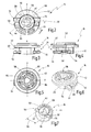
- shows a view from above of a fastening element according to a further embodiment according to the invention;
- Fig. 3
- shows a view of the fastening element of
Fig. 2 from the side; - Fig. 4
- shows a view of the fastening element of
Fig. 2 from the front; - Fig. 5
- shows a view of the fastening element of
Fig. 2 from below; - Fig. 6
- shows a perspective view of the fastening element of
Fig. 2 obliquely from below; - Fig. 7
- shows a perspective view of the fastening element of
Fig. 2 obliquely from above; - Fig. 8
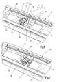
- shows a strip arrangement with a fastening element according to
Fig. 2 to 7 premounted on it; - Fig. 9
- shows the strip arrangement of
Fig. 8 after a displacement step has been carried out; and - Fig. 10
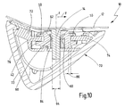
- shows a cross-sectional view through the strip arrangement of
Fig. 8 . - In
Fig. 1 , a first embodiment of a fastening arrangement is designated in general by 10. Thefastening arrangement 10 contains aworkpiece 12, such as, for example, a body panel, to the surface of which astud 14 is joined, for example by stud welding, by stud gluing or by thermoplastic welding. The surface of theworkpiece 12 extends in a plane which is spanned by coordinates x, y. Thestud 14 extends perpendicularly thereto in a direction z. The stud is preferably joined to the surface of theworkpiece 12 by means of a flange portion and has a shank portion. - The
fastening arrangement 10 has, furthermore, afastening element 16. Thefastening element 16 is designed as a hollow one-piece component (preferably made from plastic) and has astud receptacle 18 oriented in the z-direction. A plurality of blockingelements 20 are formed on the inner circumference of thestud receptacle 18 and are preferably designed to be deflectable in the radial direction. - A thread, with at least one
thread flight 22, which is illustrated diagrammatically inFig. 1 , is preferably formed on the shank of thestud 14. - The
fastening element 16 is pushed onto thestud 14 in such a way that thestud 14 is received in thestud receptacle 18 and the blockingelements 20 are pressed elastically radially into thethread flight 22, in such a way that thefastening element 16 is secured axially to thestud 14. The blockingelements 20 may be arranged, distributed over the circumference, at the same axial height or at a different axial height, as illustrated diagrammatically inFig. 1 . - The
fastening arrangement 10 has, furthermore, astructural element 26 which is secured in the axial direction to thefastening element 16. For this purpose, in the present case, thestructural element 26 has a plurality offastening fingers 28 which are arranged, distributed on the circumference, and which engage into respective radial recesses 30 on the outer circumference of thefastening element 16. Thefastening fingers 28 may likewise be deflectable elastically radially. - To produce the
fastening arrangement 10, thefastening element 16 is first premounted on thestructural element 26 in that thefastening element 16 is secured to thestructural element 26 such that thefastening fingers 28 engage into the respective radial recesses 30 of thefastening element 16. - Subsequently, the premounted arrangement consisting of the
fastening element 16 and of thestructural element 26 is pressed onto thestud 14 in the axial direction (z-direction), the blockingelements 20 engaging into thethread flight 22. - Subsequently, a
movement step 32 takes place, in which, in the present embodiment, thestructural element 26 is rotated about the longitudinal axis. In this case, as a result of the engagement of thefastening fingers 28 into the radial recesses 30, thefastening element 16 is driven, as shown at 34, so that thefastening element 16 is likewise rotated about the longitudinal axis. Since the blockingelements 20 engage on thethread flight 22, thefastening element 16 is consequently drawn in a direction towards the surface of theworkpiece 12, as shown by anaxial movement direction 36. Thestructural element 26 is in this case driven in the axial direction and can thus be pressed as far as it will go onto the surface of theworkpiece 12, engagement between the blockingelements 20 and thethread flight 22 generating a certain axial prestress. Thestructural element 26 can thereby be secured, free of rattling, to theworkpiece 12. - A
fastening element 16 of an alternative embodiment is shown inFig. 2 to 7 . Thefastening element 16 ofFig. 2 to 7 is designed, in particular, for producing a fastening arrangement, such as is shownFig. 8 to 10 . The embodiment, shown inFig. 2 to 10 , of a fastening arrangement generally corresponds in terms of set-up and functioning to the fastening arrangement ofFig. 1 . Identical elements are therefore identified by the same reference symbols. Essentially, the differences are explained below. - The
fastening element 16 ofFig. 2 to 7 has a hollow-cylindricalbasic body 40, on the outer circumference of which afirst flange portion 42 and asecond flange portion 44 are formed. Thesecond flange portion 44 extends over anangular range 46 of less than 180°, in the present case of about 130°. Theflange portions - Furthermore, two latching
noses 50 extend from thebasic body 40 and are arranged radially on opposite sides of thebasic body 40. The latchingnoses 50 are in this case aligned axially with thesecond flange portion 44 and are adjacent in the circumferential direction to thesecond flange portion 44. - Furthermore, two radially
opposite bosses 54 extend from thebasic body 40, specifically in such a way that they extend approximately parallel to the latchingnoses 50. Thebosses 54 are spaced in the circumferential direction from the latchingnoses 50. - The latching
noses 50 have in each case on their underside (on the side facing the first flange portion 42) latchingprojections 52 which project into the region of thespacing 48. - The latching
noses 50 are in this case connected to thebasic body 40 in such a way that they are deflectable elastically to a limited extent in the axial direction. - The inner space of the
basic body 40 defines astud receptacle 56. Thestud receptacle 56 has in this case threeindentations 58 which are spaced from one another in a circumferential direction and in which blockingelements 60 are secured so as to be elastically deflectable radially. The blockingelements 60 in this case extend, in the state stretched out non-elastically, obliquely downwards (from thesecond flange portion 44 towards the first flange portion 42). - The free ends of the blocking
elements 60 in this case define a diameter which is somewhat smaller than anoutside diameter 64 of the stud 14 (seeFig. 10 ). - Furthermore, the
stud receptacle 56 has anintroduction cone 62 with anintroduction diameter 66 which is preferably at least twice as large as thestud diameter 64. - The
fastening element 16 ofFig. 2 to 7 preferably serves for securing astrip arrangement 70 to aworkpiece 12. Thestrip arrangement 70, which is shown inFig. 8 to 10 , has in this case abasic strip 72 to which atrim strip 73 is secured. - The
basic strip 72 has afirst web 74 extending in the x-direction and asecond web 76 extending parallel thereto. Thewebs basic body 40. - The
webs thickness 72 which is equal to or smaller than or equal to theaxial spacing 48 between theflange portions fastening element 16 ofFig. 2 to 7 is premounted on thebasic strip 72 in such a way that it is pushed in the x-direction between thewebs bosses 54 in front. Adriver portion 80 extending in the y-direction is formed on the top side of thefirst web 74 and is designed for engaging on the assignedboss 54. Furthermore, formed on the top side of at least one of thewebs depression 82, the shape of which is adapted to the latchingprojections 42 of the latchingnoses 50. When thefastening element 16 is being pushed on axially between thewebs noses 50 are deflected axially until the latchingprojections 52 finally engage into the latchingdepressions 82. In this position, the premounting position is reached. In the premounting position, oneboss 54 is either in contact with thedriver portion 80 or, however, is preferably spaced slightly from the latter (in the x-direction). - The
basic strip 72 preferably has a plurality ofsuch webs fastening elements 16 are premounted on the respective web arrangements until a position, as shown inFig. 8 , is reached. - In the premounting position, as shown in
Fig. 8 , theintroduction cones 62 of thefastening elements 16 face away from thetrim strip 72 and face a corresponding number of studs joined to a surface of aworkpiece 12. In a mounting step, thestrip arrangement 70, together with thefastening elements 16 premounted on it, is pressed onto thestuds 14, as shown inFig. 10 . In this case, the blockingelements 60 engage on the outer circumference of the shank of thestud 14 which is preferably designed as a threaded stud with at least one thread flight. Consequently, as shown inFig. 10 , thestrip arrangement 70 is fixed in the axial direction z to thestud 14. - In a subsequent final mounting step, at least the
basic strip 72 is displaced in the x-direction, that is to say transversely with respect to the axis z of thestud 14, as shown at 32 inFig. 8 . The driver portion 8 thereby engages on the assignedboss 54. Since thefastening element 16 is then fixed radially to thestud 14, the fastening element 16 (or all the fastening elements 16) is in this case rotated, as shown at 34 inFig. 9 . In this case, the latching connection between the latchingprojections 52 and the latchingdepressions 82 is released. As a result of the rotation of thefastening elements 16, these are drawn in the manner of nuts towards theworkpiece 12, so that thestrip arrangement 70 secured axially to thefastening elements 16 is also drawn axially towards theworkpiece 12. Height compensation can thereby take place, which may occur, for example, because the blockingelements 16 engage on thevarious studs 14 in each case in different rotary positions and consequently set up a relatively different height position. - As a result of the final mounting step, these height differences are compensated, and prestress between the workpiece 12 and the
strip arrangement 70 is preferably implemented. - The basic strip may in this case have a bridge portion which bridges the
webs recess 84, the diameter of which is larger than the diameter of thestud 14, so that thestud 14 can pass, unimpeded, through therecess 84. Furthermore, thewebs radial play 86 is set up between the outer circumference of thebasic body 40 and therespective webs Fig. 10 . Thefastening elements 16 can thereby be mounted on thebasic strip 72 in a floating manner in the radial direction. Furthermore, thefastening elements 60 are also mounted in a floating manner in the radial direction x with respect to the basic strip 72 (and thetrim strip 73 firmly connected to it). Tolerances of the stud spacings and stud alignments can thereby be compensated even in the mounting step. - The
trim strip 73 can be mounted on thebasic strip 72, for example by being snapped on, after the final mounting strip has been carried out. Alternatively, it is possible to secure thetrim strip 73 to thebasic strip 72 beforehand and displace it, together with thebasic strip 72, in thedirection 32 in order to carry out the final mounting.
Claims (15)
- Method for fastening a structural element (26; 70), in particular a strip arrangement (70), to a workpiece (12), in particular to a body portion, with the steps:- securing a stud (14) to the workpiece (12);- premounting a fastening element (16) on the structural element (26; 70), the fastening element (16) having a stud receptacle (18; 56);- pushing the fastening element (16) in a longitudinal direction (z) onto the stud (14); and- moving the structural element (26; 70), a driver portion (28; 80) of the structural element (26; 70) engaging on the fastening element (16) in such a way that the fastening element (16) is rotated (34) about the longitudinal axis (z).
- Method according to Claim 1, the movement step (32) involving displacement in a direction (x) transverse with respect to the longitudinal direction (z).
- Method according to Claim 1 or 2, the stud (14) having at least one thread flight (22), and the stud receptacle (18; 56) having at least one blocking element (20; 60) engaging on the thread flight (22), so that, during the movement step (32), the fastening element (16), together with the structural element (26; 70) secured to it, is moved in the direction of the longitudinal axis (z).
- Method according to one of Claims 1 to 3, the fastening element (16) being secured to the structural element (70) by latching during the premounting step, and the latching connection (52, 82) being released during the movement step (32).
- Method according to one of Claims 1 to 4, the fastening element (16) being secured to the structural element (70) in a floating manner in at least one direction (y) transverse with respect to the longitudinal direction (z).
- Fastening element (16), in particular for carrying out the method according to one of Claims 1 to 5, with a hollow basic body (40), the inner space of which has a stud receptacle (18; 56) for the axial reception of a stud (14) and on the outside of which a fastening portion for axially securing a structural element (26; 70) is formed, there being formed, furthermore, on the basic body (40) a boss portion (30; 54) which is designed, during a movement (32) of the axially secured structural element (26; 70) transversely with respect to the axial direction, to be driven by a driver portion (28; 80) of the structural element (26; 70), so that the fastening element (16) rotates.
- Structural element according to Claim 6, the boss portion having at least one boss (54) extending radially from the basic body (40).
- Structural element according to Claim 6 or 7, at least one latching nose (50) extending radially from the basic body (40), being deflectable elastically in the axial direction (z) and being designed to engage into a latching depression (82) of the structural element (70) when the structural element (70) is premounted on the fastening element (16).
- Structural element according to one of Claims 6 to 8, the fastening portion having a first flange portion (42) and a second flange portion (44) which is spaced axially from the first flange portion (42).
- Structural element according to Claim 9, the second flange portion (44) being aligned in the axial direction with a boss portion (54) and/or with a latching nose (50).
- Structural element according to Claim 9 or 10, the second flange portion (44) extending in the circumferential direction over an angular range (46) of less than 180°.
- Structural element according to one of Claims 6 to 11, the stud receptacle (18; 56) having at least one blocking element (20; 60) deflectable elastically in the radial direction.
- Fastening arrangement (10) with a stud (14) which is joined to a surface of a workpiece (12) and with a fastening element (16) which has a stud receptacle (18) and a fastening portion (24), the fastening element (16) being pushed onto the stud (14), and a structural element (26; 70) being secured axially to the fastening element (16), the fastening element being a fastening element (16) according to one of Claims 6 to 12 and/or the fastening arrangement (10) being produced by means of a method according to one of Claims 1 to 5.
- Fastening arrangement according to Claim 13, the structural element being a strip arrangement (70) which is secured to the workpiece (12) by means of a plurality of fastening arrangements (10).
- Fastening arrangement according to Claim 13 or 14, a trim element (73) which covers the fastening arrangement (10) being secured to the structural element (70).
Applications Claiming Priority (1)
| Application Number | Priority Date | Filing Date | Title |
|---|---|---|---|
| DE102011117779A DE102011117779A1 (en) | 2011-11-03 | 2011-11-03 | Mounting method, fastener and mounting arrangement |
Publications (2)
| Publication Number | Publication Date |
|---|---|
| EP2589825A1 true EP2589825A1 (en) | 2013-05-08 |
| EP2589825B1 EP2589825B1 (en) | 2018-05-30 |
Family
ID=46785278
Family Applications (1)
| Application Number | Title | Priority Date | Filing Date |
|---|---|---|---|
| EP12182425.4A Not-in-force EP2589825B1 (en) | 2011-11-03 | 2012-08-30 | Fastening method and fastening arrangement |
Country Status (3)
| Country | Link |
|---|---|
| EP (1) | EP2589825B1 (en) |
| JP (1) | JP2013096580A (en) |
| DE (1) | DE102011117779A1 (en) |
Families Citing this family (1)
| Publication number | Priority date | Publication date | Assignee | Title |
|---|---|---|---|---|
| US20220065281A1 (en) * | 2020-09-03 | 2022-03-03 | Milbank Manufacturing Co. | Plumb adjuster for electrical enclosure |
Citations (1)
| Publication number | Priority date | Publication date | Assignee | Title |
|---|---|---|---|---|
| EP0115671A1 (en) * | 1983-01-11 | 1984-08-15 | Dzus Fastener Europe Limited | Quick release fastener |
Family Cites Families (3)
| Publication number | Priority date | Publication date | Assignee | Title |
|---|---|---|---|---|
| FR1155930A (en) * | 1956-07-06 | 1958-05-09 | Advanced clamping and fastening device with screw and nut | |
| US4846612A (en) * | 1987-10-19 | 1989-07-11 | Shur-Lok Corporation | Sandwich panel fastener |
| US7802953B2 (en) * | 2007-03-16 | 2010-09-28 | Robert Stephen | Inset panel fastener |
-
2011
- 2011-11-03 DE DE102011117779A patent/DE102011117779A1/en not_active Withdrawn
-
2012
- 2012-08-30 EP EP12182425.4A patent/EP2589825B1/en not_active Not-in-force
- 2012-10-31 JP JP2012240055A patent/JP2013096580A/en active Pending
Patent Citations (1)
| Publication number | Priority date | Publication date | Assignee | Title |
|---|---|---|---|---|
| EP0115671A1 (en) * | 1983-01-11 | 1984-08-15 | Dzus Fastener Europe Limited | Quick release fastener |
Also Published As
| Publication number | Publication date |
|---|---|
| EP2589825B1 (en) | 2018-05-30 |
| DE102011117779A1 (en) | 2013-05-08 |
| JP2013096580A (en) | 2013-05-20 |
Similar Documents
| Publication | Publication Date | Title |
|---|---|---|
| EP2233755B1 (en) | Fastening clip and associated fastener | |
| US9038876B2 (en) | Radar mounting device | |
| US6824203B2 (en) | Apparatus and method for attaching undercover onto underside of car floor panel | |
| US20090261619A1 (en) | Air-directing component and body front end of a motor vehicle | |
| EP2589825B1 (en) | Fastening method and fastening arrangement | |
| US9333554B2 (en) | Panel fastening rivet mechanism | |
| CN105324582B (en) | Systems with load bearing components | |
| US11808296B2 (en) | System and method for fastening and locating one vehicle component relative to another vehicle component without using mechanical fasteners | |
| JP6351909B2 (en) | Sensor holder and sensor device | |
| US11592049B2 (en) | Device for fastening a light strip to a motor vehicle | |
| US8684450B2 (en) | Vehicle structure and method of assembly | |
| CN111148909B (en) | Nut carrier system comprising nut carrier and nut carrier mounting support | |
| WO2007074886A1 (en) | Mounting structure | |
| WO2013167325A1 (en) | Body | |
| JP3599065B2 (en) | Temporary fixing structure for parts | |
| EP1284219B1 (en) | Structure for attaching a part to a vehicle | |
| US10328979B2 (en) | Connecting device for connecting an adjustable spoiler blade to a vehicle | |
| JP5182161B2 (en) | Wire harness clamp | |
| JP5851388B2 (en) | Mounting structure with retainer and grommet | |
| US20190242419A1 (en) | System for fastening a planar element to a component and fastening clip for use in such a system | |
| US20190111977A1 (en) | Motor vehicle | |
| JP7211849B2 (en) | Fastener | |
| US10228006B2 (en) | Method for producing a fastening arrangement, and such fastening arrangement | |
| US20140057501A1 (en) | Electrical-mechanical fastening device for motor vehicles | |
| US20140227059A1 (en) | Permanent screw attachment |
Legal Events
| Date | Code | Title | Description |
|---|---|---|---|
| PUAI | Public reference made under article 153(3) epc to a published international application that has entered the european phase |
Free format text: ORIGINAL CODE: 0009012 |
|
| AK | Designated contracting states |
Kind code of ref document: A1 Designated state(s): AL AT BE BG CH CY CZ DE DK EE ES FI FR GB GR HR HU IE IS IT LI LT LU LV MC MK MT NL NO PL PT RO RS SE SI SK SM TR |
|
| AX | Request for extension of the european patent |
Extension state: BA ME |
|
| 17P | Request for examination filed |
Effective date: 20131023 |
|
| RBV | Designated contracting states (corrected) |
Designated state(s): AL AT BE BG CH CY CZ DE DK EE ES FI FR GB GR HR HU IE IS IT LI LT LU LV MC MK MT NL NO PL PT RO RS SE SI SK SM TR |
|
| 17Q | First examination report despatched |
Effective date: 20150318 |
|
| RAP1 | Party data changed (applicant data changed or rights of an application transferred) |
Owner name: NEWFREY LLC |
|
| STAA | Information on the status of an ep patent application or granted ep patent |
Free format text: STATUS: EXAMINATION IS IN PROGRESS |
|
| GRAP | Despatch of communication of intention to grant a patent |
Free format text: ORIGINAL CODE: EPIDOSNIGR1 |
|
| STAA | Information on the status of an ep patent application or granted ep patent |
Free format text: STATUS: GRANT OF PATENT IS INTENDED |
|
| INTG | Intention to grant announced |
Effective date: 20180223 |
|
| GRAS | Grant fee paid |
Free format text: ORIGINAL CODE: EPIDOSNIGR3 |
|
| GRAA | (expected) grant |
Free format text: ORIGINAL CODE: 0009210 |
|
| STAA | Information on the status of an ep patent application or granted ep patent |
Free format text: STATUS: THE PATENT HAS BEEN GRANTED |
|
| AK | Designated contracting states |
Kind code of ref document: B1 Designated state(s): AL AT BE BG CH CY CZ DE DK EE ES FI FR GB GR HR HU IE IS IT LI LT LU LV MC MK MT NL NO PL PT RO RS SE SI SK SM TR |
|
| REG | Reference to a national code |
Ref country code: GB Ref legal event code: FG4D |
|
| REG | Reference to a national code |
Ref country code: CH Ref legal event code: EP |
|
| REG | Reference to a national code |
Ref country code: AT Ref legal event code: REF Ref document number: 1003897 Country of ref document: AT Kind code of ref document: T Effective date: 20180615 |
|
| REG | Reference to a national code |
Ref country code: IE Ref legal event code: FG4D |
|
| REG | Reference to a national code |
Ref country code: DE Ref legal event code: R096 Ref document number: 602012046807 Country of ref document: DE |
|
| REG | Reference to a national code |
Ref country code: NL Ref legal event code: MP Effective date: 20180530 |
|
| REG | Reference to a national code |
Ref country code: LT Ref legal event code: MG4D |
|
| PG25 | Lapsed in a contracting state [announced via postgrant information from national office to epo] |
Ref country code: LT Free format text: LAPSE BECAUSE OF FAILURE TO SUBMIT A TRANSLATION OF THE DESCRIPTION OR TO PAY THE FEE WITHIN THE PRESCRIBED TIME-LIMIT Effective date: 20180530 Ref country code: ES Free format text: LAPSE BECAUSE OF FAILURE TO SUBMIT A TRANSLATION OF THE DESCRIPTION OR TO PAY THE FEE WITHIN THE PRESCRIBED TIME-LIMIT Effective date: 20180530 Ref country code: CY Free format text: LAPSE BECAUSE OF FAILURE TO SUBMIT A TRANSLATION OF THE DESCRIPTION OR TO PAY THE FEE WITHIN THE PRESCRIBED TIME-LIMIT Effective date: 20180530 Ref country code: BG Free format text: LAPSE BECAUSE OF FAILURE TO SUBMIT A TRANSLATION OF THE DESCRIPTION OR TO PAY THE FEE WITHIN THE PRESCRIBED TIME-LIMIT Effective date: 20180830 Ref country code: FI Free format text: LAPSE BECAUSE OF FAILURE TO SUBMIT A TRANSLATION OF THE DESCRIPTION OR TO PAY THE FEE WITHIN THE PRESCRIBED TIME-LIMIT Effective date: 20180530 Ref country code: SE Free format text: LAPSE BECAUSE OF FAILURE TO SUBMIT A TRANSLATION OF THE DESCRIPTION OR TO PAY THE FEE WITHIN THE PRESCRIBED TIME-LIMIT Effective date: 20180530 Ref country code: NO Free format text: LAPSE BECAUSE OF FAILURE TO SUBMIT A TRANSLATION OF THE DESCRIPTION OR TO PAY THE FEE WITHIN THE PRESCRIBED TIME-LIMIT Effective date: 20180830 |
|
| PG25 | Lapsed in a contracting state [announced via postgrant information from national office to epo] |
Ref country code: GR Free format text: LAPSE BECAUSE OF FAILURE TO SUBMIT A TRANSLATION OF THE DESCRIPTION OR TO PAY THE FEE WITHIN THE PRESCRIBED TIME-LIMIT Effective date: 20180831 Ref country code: LV Free format text: LAPSE BECAUSE OF FAILURE TO SUBMIT A TRANSLATION OF THE DESCRIPTION OR TO PAY THE FEE WITHIN THE PRESCRIBED TIME-LIMIT Effective date: 20180530 Ref country code: RS Free format text: LAPSE BECAUSE OF FAILURE TO SUBMIT A TRANSLATION OF THE DESCRIPTION OR TO PAY THE FEE WITHIN THE PRESCRIBED TIME-LIMIT Effective date: 20180530 Ref country code: HR Free format text: LAPSE BECAUSE OF FAILURE TO SUBMIT A TRANSLATION OF THE DESCRIPTION OR TO PAY THE FEE WITHIN THE PRESCRIBED TIME-LIMIT Effective date: 20180530 |
|
| REG | Reference to a national code |
Ref country code: AT Ref legal event code: MK05 Ref document number: 1003897 Country of ref document: AT Kind code of ref document: T Effective date: 20180530 |
|
| PG25 | Lapsed in a contracting state [announced via postgrant information from national office to epo] |
Ref country code: NL Free format text: LAPSE BECAUSE OF FAILURE TO SUBMIT A TRANSLATION OF THE DESCRIPTION OR TO PAY THE FEE WITHIN THE PRESCRIBED TIME-LIMIT Effective date: 20180530 |
|
| PG25 | Lapsed in a contracting state [announced via postgrant information from national office to epo] |
Ref country code: PL Free format text: LAPSE BECAUSE OF FAILURE TO SUBMIT A TRANSLATION OF THE DESCRIPTION OR TO PAY THE FEE WITHIN THE PRESCRIBED TIME-LIMIT Effective date: 20180530 Ref country code: SK Free format text: LAPSE BECAUSE OF FAILURE TO SUBMIT A TRANSLATION OF THE DESCRIPTION OR TO PAY THE FEE WITHIN THE PRESCRIBED TIME-LIMIT Effective date: 20180530 Ref country code: CZ Free format text: LAPSE BECAUSE OF FAILURE TO SUBMIT A TRANSLATION OF THE DESCRIPTION OR TO PAY THE FEE WITHIN THE PRESCRIBED TIME-LIMIT Effective date: 20180530 Ref country code: RO Free format text: LAPSE BECAUSE OF FAILURE TO SUBMIT A TRANSLATION OF THE DESCRIPTION OR TO PAY THE FEE WITHIN THE PRESCRIBED TIME-LIMIT Effective date: 20180530 Ref country code: DK Free format text: LAPSE BECAUSE OF FAILURE TO SUBMIT A TRANSLATION OF THE DESCRIPTION OR TO PAY THE FEE WITHIN THE PRESCRIBED TIME-LIMIT Effective date: 20180530 Ref country code: AT Free format text: LAPSE BECAUSE OF FAILURE TO SUBMIT A TRANSLATION OF THE DESCRIPTION OR TO PAY THE FEE WITHIN THE PRESCRIBED TIME-LIMIT Effective date: 20180530 Ref country code: EE Free format text: LAPSE BECAUSE OF FAILURE TO SUBMIT A TRANSLATION OF THE DESCRIPTION OR TO PAY THE FEE WITHIN THE PRESCRIBED TIME-LIMIT Effective date: 20180530 |
|
| PG25 | Lapsed in a contracting state [announced via postgrant information from national office to epo] |
Ref country code: IT Free format text: LAPSE BECAUSE OF FAILURE TO SUBMIT A TRANSLATION OF THE DESCRIPTION OR TO PAY THE FEE WITHIN THE PRESCRIBED TIME-LIMIT Effective date: 20180530 Ref country code: SM Free format text: LAPSE BECAUSE OF FAILURE TO SUBMIT A TRANSLATION OF THE DESCRIPTION OR TO PAY THE FEE WITHIN THE PRESCRIBED TIME-LIMIT Effective date: 20180530 |
|
| REG | Reference to a national code |
Ref country code: DE Ref legal event code: R097 Ref document number: 602012046807 Country of ref document: DE |
|
| PG25 | Lapsed in a contracting state [announced via postgrant information from national office to epo] |
Ref country code: MC Free format text: LAPSE BECAUSE OF FAILURE TO SUBMIT A TRANSLATION OF THE DESCRIPTION OR TO PAY THE FEE WITHIN THE PRESCRIBED TIME-LIMIT Effective date: 20180530 |
|
| REG | Reference to a national code |
Ref country code: CH Ref legal event code: PL |
|
| PLBE | No opposition filed within time limit |
Free format text: ORIGINAL CODE: 0009261 |
|
| STAA | Information on the status of an ep patent application or granted ep patent |
Free format text: STATUS: NO OPPOSITION FILED WITHIN TIME LIMIT |
|
| GBPC | Gb: european patent ceased through non-payment of renewal fee |
Effective date: 20180830 |
|
| PG25 | Lapsed in a contracting state [announced via postgrant information from national office to epo] |
Ref country code: CH Free format text: LAPSE BECAUSE OF NON-PAYMENT OF DUE FEES Effective date: 20180831 Ref country code: LI Free format text: LAPSE BECAUSE OF NON-PAYMENT OF DUE FEES Effective date: 20180831 Ref country code: LU Free format text: LAPSE BECAUSE OF NON-PAYMENT OF DUE FEES Effective date: 20180830 |
|
| 26N | No opposition filed |
Effective date: 20190301 |
|
| REG | Reference to a national code |
Ref country code: BE Ref legal event code: MM Effective date: 20180831 |
|
| PG25 | Lapsed in a contracting state [announced via postgrant information from national office to epo] |
Ref country code: SI Free format text: LAPSE BECAUSE OF FAILURE TO SUBMIT A TRANSLATION OF THE DESCRIPTION OR TO PAY THE FEE WITHIN THE PRESCRIBED TIME-LIMIT Effective date: 20180530 |
|
| PG25 | Lapsed in a contracting state [announced via postgrant information from national office to epo] |
Ref country code: FR Free format text: LAPSE BECAUSE OF NON-PAYMENT OF DUE FEES Effective date: 20180831 Ref country code: BE Free format text: LAPSE BECAUSE OF NON-PAYMENT OF DUE FEES Effective date: 20180831 |
|
| PG25 | Lapsed in a contracting state [announced via postgrant information from national office to epo] |
Ref country code: GB Free format text: LAPSE BECAUSE OF NON-PAYMENT OF DUE FEES Effective date: 20180830 |
|
| PG25 | Lapsed in a contracting state [announced via postgrant information from national office to epo] |
Ref country code: AL Free format text: LAPSE BECAUSE OF FAILURE TO SUBMIT A TRANSLATION OF THE DESCRIPTION OR TO PAY THE FEE WITHIN THE PRESCRIBED TIME-LIMIT Effective date: 20180530 |
|
| PG25 | Lapsed in a contracting state [announced via postgrant information from national office to epo] |
Ref country code: MT Free format text: LAPSE BECAUSE OF NON-PAYMENT OF DUE FEES Effective date: 20180830 |
|
| PG25 | Lapsed in a contracting state [announced via postgrant information from national office to epo] |
Ref country code: TR Free format text: LAPSE BECAUSE OF FAILURE TO SUBMIT A TRANSLATION OF THE DESCRIPTION OR TO PAY THE FEE WITHIN THE PRESCRIBED TIME-LIMIT Effective date: 20180530 |
|
| PG25 | Lapsed in a contracting state [announced via postgrant information from national office to epo] |
Ref country code: HU Free format text: LAPSE BECAUSE OF FAILURE TO SUBMIT A TRANSLATION OF THE DESCRIPTION OR TO PAY THE FEE WITHIN THE PRESCRIBED TIME-LIMIT; INVALID AB INITIO Effective date: 20120830 Ref country code: PT Free format text: LAPSE BECAUSE OF FAILURE TO SUBMIT A TRANSLATION OF THE DESCRIPTION OR TO PAY THE FEE WITHIN THE PRESCRIBED TIME-LIMIT Effective date: 20180530 |
|
| PG25 | Lapsed in a contracting state [announced via postgrant information from national office to epo] |
Ref country code: MK Free format text: LAPSE BECAUSE OF NON-PAYMENT OF DUE FEES Effective date: 20180530 Ref country code: IE Free format text: LAPSE BECAUSE OF NON-PAYMENT OF DUE FEES Effective date: 20180830 |
|
| PG25 | Lapsed in a contracting state [announced via postgrant information from national office to epo] |
Ref country code: IS Free format text: LAPSE BECAUSE OF FAILURE TO SUBMIT A TRANSLATION OF THE DESCRIPTION OR TO PAY THE FEE WITHIN THE PRESCRIBED TIME-LIMIT Effective date: 20180930 |
|
| PGFP | Annual fee paid to national office [announced via postgrant information from national office to epo] |
Ref country code: DE Payment date: 20220608 Year of fee payment: 11 |
|
| REG | Reference to a national code |
Ref country code: DE Ref legal event code: R119 Ref document number: 602012046807 Country of ref document: DE |
|
| PG25 | Lapsed in a contracting state [announced via postgrant information from national office to epo] |
Ref country code: DE Free format text: LAPSE BECAUSE OF NON-PAYMENT OF DUE FEES Effective date: 20240301 |