EP2589800A1 - Windmill pitch control device - Google Patents
Windmill pitch control device Download PDFInfo
- Publication number
- EP2589800A1 EP2589800A1 EP11800730.1A EP11800730A EP2589800A1 EP 2589800 A1 EP2589800 A1 EP 2589800A1 EP 11800730 A EP11800730 A EP 11800730A EP 2589800 A1 EP2589800 A1 EP 2589800A1
- Authority
- EP
- European Patent Office
- Prior art keywords
- electricity
- power source
- motor
- controller
- pitch
- Prior art date
- Legal status (The legal status is an assumption and is not a legal conclusion. Google has not performed a legal analysis and makes no representation as to the accuracy of the status listed.)
- Granted
Links
Images


Classifications
-
- F—MECHANICAL ENGINEERING; LIGHTING; HEATING; WEAPONS; BLASTING
- F03—MACHINES OR ENGINES FOR LIQUIDS; WIND, SPRING, OR WEIGHT MOTORS; PRODUCING MECHANICAL POWER OR A REACTIVE PROPULSIVE THRUST, NOT OTHERWISE PROVIDED FOR
- F03D—WIND MOTORS
- F03D7/00—Controlling wind motors
- F03D7/02—Controlling wind motors the wind motors having rotation axis substantially parallel to the air flow entering the rotor
- F03D7/022—Adjusting aerodynamic properties of the blades
- F03D7/0224—Adjusting blade pitch
-
- F—MECHANICAL ENGINEERING; LIGHTING; HEATING; WEAPONS; BLASTING
- F03—MACHINES OR ENGINES FOR LIQUIDS; WIND, SPRING, OR WEIGHT MOTORS; PRODUCING MECHANICAL POWER OR A REACTIVE PROPULSIVE THRUST, NOT OTHERWISE PROVIDED FOR
- F03D—WIND MOTORS
- F03D7/00—Controlling wind motors
- F03D7/02—Controlling wind motors the wind motors having rotation axis substantially parallel to the air flow entering the rotor
- F03D7/028—Controlling wind motors the wind motors having rotation axis substantially parallel to the air flow entering the rotor controlling wind motor output power
- F03D7/0284—Controlling wind motors the wind motors having rotation axis substantially parallel to the air flow entering the rotor controlling wind motor output power in relation to the state of the electric grid
-
- F—MECHANICAL ENGINEERING; LIGHTING; HEATING; WEAPONS; BLASTING
- F05—INDEXING SCHEMES RELATING TO ENGINES OR PUMPS IN VARIOUS SUBCLASSES OF CLASSES F01-F04
- F05B—INDEXING SCHEME RELATING TO WIND, SPRING, WEIGHT, INERTIA OR LIKE MOTORS, TO MACHINES OR ENGINES FOR LIQUIDS COVERED BY SUBCLASSES F03B, F03D AND F03G
- F05B2260/00—Function
- F05B2260/42—Storage of energy
-
- F—MECHANICAL ENGINEERING; LIGHTING; HEATING; WEAPONS; BLASTING
- F05—INDEXING SCHEMES RELATING TO ENGINES OR PUMPS IN VARIOUS SUBCLASSES OF CLASSES F01-F04
- F05B—INDEXING SCHEME RELATING TO WIND, SPRING, WEIGHT, INERTIA OR LIKE MOTORS, TO MACHINES OR ENGINES FOR LIQUIDS COVERED BY SUBCLASSES F03B, F03D AND F03G
- F05B2260/00—Function
- F05B2260/70—Adjusting of angle of incidence or attack of rotating blades
- F05B2260/76—Adjusting of angle of incidence or attack of rotating blades the adjusting mechanism using auxiliary power sources
-
- F—MECHANICAL ENGINEERING; LIGHTING; HEATING; WEAPONS; BLASTING
- F05—INDEXING SCHEMES RELATING TO ENGINES OR PUMPS IN VARIOUS SUBCLASSES OF CLASSES F01-F04
- F05B—INDEXING SCHEME RELATING TO WIND, SPRING, WEIGHT, INERTIA OR LIKE MOTORS, TO MACHINES OR ENGINES FOR LIQUIDS COVERED BY SUBCLASSES F03B, F03D AND F03G
- F05B2270/00—Control
- F05B2270/10—Purpose of the control system
- F05B2270/107—Purpose of the control system to cope with emergencies
-
- F—MECHANICAL ENGINEERING; LIGHTING; HEATING; WEAPONS; BLASTING
- F05—INDEXING SCHEMES RELATING TO ENGINES OR PUMPS IN VARIOUS SUBCLASSES OF CLASSES F01-F04
- F05B—INDEXING SCHEME RELATING TO WIND, SPRING, WEIGHT, INERTIA OR LIKE MOTORS, TO MACHINES OR ENGINES FOR LIQUIDS COVERED BY SUBCLASSES F03B, F03D AND F03G
- F05B2270/00—Control
- F05B2270/10—Purpose of the control system
- F05B2270/107—Purpose of the control system to cope with emergencies
- F05B2270/1074—Purpose of the control system to cope with emergencies by using back-up controls
-
- F—MECHANICAL ENGINEERING; LIGHTING; HEATING; WEAPONS; BLASTING
- F05—INDEXING SCHEMES RELATING TO ENGINES OR PUMPS IN VARIOUS SUBCLASSES OF CLASSES F01-F04
- F05B—INDEXING SCHEME RELATING TO WIND, SPRING, WEIGHT, INERTIA OR LIKE MOTORS, TO MACHINES OR ENGINES FOR LIQUIDS COVERED BY SUBCLASSES F03B, F03D AND F03G
- F05B2270/00—Control
- F05B2270/60—Control system actuates through
- F05B2270/602—Control system actuates through electrical actuators
-
- Y—GENERAL TAGGING OF NEW TECHNOLOGICAL DEVELOPMENTS; GENERAL TAGGING OF CROSS-SECTIONAL TECHNOLOGIES SPANNING OVER SEVERAL SECTIONS OF THE IPC; TECHNICAL SUBJECTS COVERED BY FORMER USPC CROSS-REFERENCE ART COLLECTIONS [XRACs] AND DIGESTS
- Y02—TECHNOLOGIES OR APPLICATIONS FOR MITIGATION OR ADAPTATION AGAINST CLIMATE CHANGE
- Y02E—REDUCTION OF GREENHOUSE GAS [GHG] EMISSIONS, RELATED TO ENERGY GENERATION, TRANSMISSION OR DISTRIBUTION
- Y02E10/00—Energy generation through renewable energy sources
- Y02E10/70—Wind energy
- Y02E10/72—Wind turbines with rotation axis in wind direction
Definitions
- the present invention relates to a windmill pitch control device that includes an electricity accumulator capable of applying electricity to an electric motor connected to a pitch drive device for changing the pitch angle of a blade of a windmill that is provided rotatably on a main shaft portion of the windmill, and that is able to control the pitch angle of the blade with electricity of the electricity accumulator such that the pitch angle is changed in a direction in which the wind pressure exerted on the blade is reduced.
- a windmill may be provided with a windmill pitch control device that controls the pitch angle of blades provided rotatably on a main shaft portion of the windmill.
- a windmill pitch control device that includes a battery serving as an electricity accumulator capable of applying electricity to an electric motor coupled to a pitch drive device for changing the pitch angle of a blade of a windmill, and that controls the pitch angle of the blade with the electricity of the battery so as to change the pitch angle in a direction in which the wind pressure exerted on the blade is reduced (see Patent Document 1).
- the electric motor coupled to the pitch drive device is driven as a result of electricity being supplied to the electric motor from an external power source via an electricity controller (221), which serves as a motor controller that controls supply of electricity to the electric motor coupled to the pitch drive device to control operation of the electric motor.
- the external power source is provided as a main power source that is a power source for supplying electricity during normal operation.
- the source of electricity to the electric motor coupled to the pitch drive device is switched from the main power source to a battery (220) by the electricity controller.
- the pitch angle of the blade is controlled such that the pitch angle is changed in a direction in which the wind pressure exerted on the blade is reduced (such that feathering of the blade is performed). This is aimed at preventing the windmill from being damaged by an abnormal increase in the rotational speed of the blades and the main shaft portion.
- Patent Document 1 JP2003-222070A (page 5, FIG. 3 )
- the windmill pitch control device disclosed in Patent Document 1 is configured such that in the case where a loss of an electricity supply capability of the main power source has occurred due to occurrence of power failure, feathering is performed for changing the pitch angle in a direction in which the wind pressure exerted on the blade is reduced, by supplying electricity from the battery.
- feathering is performed as mentioned above at the time of a loss of the electricity supply capability of the main power source, and therefore, pitch control for changing the pitch angle of the blade cannot be performed. Accordingly, the windmill pitch control device has a problem of inability to continue to generate electricity because the pitch control necessary for electricity generation cannot be performed at the time of a loss of the electricity supply capability of the main power source.
- a windmill pitch control device for achieving the above-stated object is a windmill pitch control device that includes an electricity accumulator capable of applying electricity to an electric motor coupled to a pitch drive device for changing a pitch angle of a blade of a windmill that is provided rotatably on a main shaft portion of the windmill, and that is able to control the pitch angle of the blade with the electricity of the electricity accumulator such that the pitch angle is changed in a direction in which a wind pressure exerted on the blade is reduced, the windmill pitch control device comprising: a motor controller that controls storage and discharge of the electricity in and from the electricity accumulator, and controls the electric motor based on a control signal for pitch control for changing the pitch angle of the blade from a pitch controller that transmits the control signal; and an electricity accumulator operation monitoring portion that monitors an operational state of the electricity accumulator, wherein the motor controller is connected to a main power source that is a power source for supplying electricity during normal operation such that the electricity is supplied
- the motor controller controls the electric motor with the electricity supplied from the electricity accumulator to continue the pitch control, based on the control signal from the pitch controller. Therefore, with the windmill pitch control device according to the present invention, it is possible to continue to generate electricity even at the time of loss of the power supply capability of the main power source. Furthermore, with the windmill pitch control device according to the present invention, feathering is performed for changing the pitch angle in a direction in which the wind pressure exerted on the blade is reduced, based on the result of monitoring by the electricity accumulator operation monitoring portion that monitors the operational state of the electricity accumulator. Thus, the windmill is prevented from being damaged due to an abnormal increase in the rotational speed of the blade and the main shaft portion.
- the present invention it is possible to provide a windmill pitch control device capable of performing feathering, and continuing to generate electricity even at the time of a loss of the electricity supply capability of the main power source.
- a windmill pitch control device is the windmill pitch control device of the first aspect, wherein a plurality of the motor controllers are provided in one-to-one correspondence to a plurality of the blades provided on the windmill, and if an abnormality has occurred in any of the motor controllers, the pitch control for the blade corresponding to an abnormal controller that is the motor controller in which the abnormality has occurred is performed by a normal controller that is the motor controller which is normal and different from the abnormal controller.
- the pitch control for the blade corresponding to the abnormal controller is performed by the normal controller that is different from the abnormal controller. Therefore, it is possible to continue to generate electricity not only at the time of a loss of the electricity supply capability of the main power source, but also in the case where an abnormality has occurred in any of the motor controllers.
- a windmill pitch control device is the windmill pitch control device of the first aspect, wherein the electric motor is provided as an induction motor, and the windmill pitch control device further comprises: a normal drive line that connects the motor controller to the electric motor, and is able to supply the electricity to the electric motor during the normal operation; a direct drive line that connects directly, or via the normal drive line, the electric motor to a direct power source provided as an alternating-current power source which is different from the main power source, and that is able to supply the electricity from the direct power source to the electric motor and drive the electric motor; a normal-drive switch that is provided on the normal drive line and is able to switch between a state where the motor controller and the electric motor are connected to each other and a state where they are disconnected from each other; a direct drive switch that is provided on the direct drive line and is able to switch between a state where the direct power source and the electric motor are connected to each other and a state where they are disconnected from each other; and a pitch angle
- the normal drive line and the normal drive switch provided on this normal drive line, the direct drive line that connects the alternating-current direct power source to the induction motor and the direct drive switch provided on this direct drive line, and the pitch angle detector are provided. Therefore, at the time of a loss of the electricity supply capability of the main power source, it is possible to perform, with the electricity of the direct power source, feathering for changing the pitch angle in a direction in which the wind pressure is exerted on the blade, by turning the direct drive switch to the on state after turning the normal drive switch to the off state.
- feathering can be performed also with the electricity of the direct power source, and it is therefore possible to perform feathering even if the capability of the electricity accumulator has degraded or an abnormality has occurred in the electricity accumulator while the pitch control is being performed with the electricity of the electricity accumulator.
- a windmill pitch control device is the windmill pitch control device of the third aspect, wherein a plurality of the motor controllers, a plurality of the pitch angle detectors, a plurality of the direct drive lines, a plurality of the direct drive switches, a plurality of the normal drive lines, and a plurality of the normal drive switches are provided in one-to-one correspondence to a plurality of the blades provided on the windmill, the direct drive lines are connected to the same direct power source via a common direct drive line provided to be shared by the direct drive lines, and the common direct drive line is provided with a direct power source switch capable of switching between a state where the direct power source and the direct drive lines are connected to each other and a state where they are disconnected from each other.
- the motor controllers, the pitch angle detectors, the direct drive lines, the direct drive switches, the normal drive lines, and the normal drive switches are provided so as to correspond to the respective blades.
- the direct drive lines are connected to the same direct power source via the common direct drive line, and the direct power source switch is provided on this common direct drive line. Therefore, a circuit can be configured in which the direct power source switch is in the off state and the normal drive switch and the direct drive switch corresponding to one blade are in the on state, while the normal drive switch corresponding to another blade is in the off state, and the direct drive switch corresponding to this blade is in the on state.
- the motor controller corresponding to one blade can control the electric motor for changing the pitch angle of another blade.
- a windmill pitch control device is the windmill pitch control device of the fourth aspect, wherein each of the normal drive lines is provided with an independent drive switch between the normal drive switches and the electric motors, the independent drive switch being able to switch between a state where the normal drive switches and the electric motors are connected to each other and a state where they are disconnected from each other, the direct drive lines are connected to the respective normal drive lines between the normal drive switches and the independent drive switches, each of the pitch angle detectors is connected to all of the motor controllers so as to be able to transmit a detection result signal thereto, and if an abnormality has occurred in any of the motor controllers, the pitch control for the blade corresponding to an abnormal controller that is the motor controller in which the abnormality has occurred and the pitch control for the blade corresponding to a normal controller that is the motor controller which is normal and different from the abnormal controller are independently performed by the normal controller as a result of the independent drive switch corresponding to the normal controller and the independent drive switch corresponding to the abnormal controller being switched.
- the result of detection by the pitch angle detector corresponding to each blade is transmitted to all of the motor controllers, and the independent drive switch is provided between the electric motor and both a point of the direct drive line located on the normal drive line and the normal drive switch. If an abnormality has occurred in any of the motor controllers, the pitch control for the blade corresponding to the normal controller, which is different from the abnormal controller, and the pitch control for the blade corresponding to the abnormal controller are independently performed by the normal controller, as a result of the independent drive switch being switched.
- the windmill pitch control device capable of performing feathering with the electricity of the direct power source at the time of a loss of the electricity supply capability of the main power source, even if an abnormality has occurred in any of the motor controllers, it is possible to continue independent pitch control for each blade with another normal motor controller, and thus to continue to generate electricity.
- a windmill pitch control device is the windmill pitch control device of any one of the first to fifth aspects, wherein a plurality of the electricity accumulators are provided in one-to-one correspondence to a plurality of the motor controllers, a plurality of main power source lines connected to the respective motor controllers are provided so as to supply electricity from the main power source thereto, the main power source lines are connected to the same main power source via a common main power source line provided to be shared by the main power source lines, and the common main power source line is provided with a main power source switch capable of switching between a state where the main power source and the main power source lines are connected to each other and a state where they are disconnected from each other.
- the electricity accumulator and the main power source line that supplies electricity from the main power source are provided so as to correspond to each motor controller.
- the main power source lines are connected to the same main power source via the common main power source line, and the main power source switch is provided on this common main power source line. Therefore, while the main power source switch is in the off state, electricity can be supplied from the electricity accumulator corresponding to one motor controller to the electricity accumulator corresponding to another motor controller via the main power source lines and the common main power source line (or only via both main power source lines if the electricity accumulator can be connected without via the common main power source line).
- this electricity accumulator can be supplemented by the power of the electricity accumulator corresponding to another motor controller. Furthermore, even if the remaining power of the electricity accumulator corresponding to any of the motor controllers has become low, this electricity accumulator can be supplemented by the power of another electricity accumulator, and it is therefore possible to maintain independent pitch control for each blade.
- a windmill pitch control device is the windmill pitch control device of any one of the first to sixth aspects, wherein an electricity accumulator remaining power detector that detects a remaining power of the electricity accumulator is provided as the electricity accumulator operation monitoring portion, and if the remaining power detected by the electricity accumulator remaining power detector is smaller than or equal to a predetermined value while the motor controller is continuing the pitch control with the electricity supplied from the electricity accumulator, the pitch angle of the blade is controlled such that the pitch angle is changed in a direction in which the wind pressure exerted on the blade is reduced.
- the electricity accumulator remaining power detector is provided as the electricity accumulator operation monitoring portion, and feathering is performed if the remaining power detected by the electricity accumulator remaining power detector is smaller than or equal to the predetermined value while the pitch control is being continued with the electricity of the electricity accumulator. Therefore, a configuration can be readily implemented in which feathering is performed before feathering becomes impossible due to a lack of the power of the electricity accumulator.
- the present invention it is possible to provide a windmill pitch control device capable of performing feathering, and continuing to generate electricity even at the time of a loss of the electricity supply capability of the main power source.
- windmill pitch control devices that include an electricity accumulator capable of applying electricity to an electric motor coupled to a pitch drive device for changing the pitch angle of blades of a windmill that are provided rotatably on a main shaft portion of the windmill, and that is able to control the pitch angle of the blades with the electricity of the electricity accumulator such that the pitch angle is changed in a direction in which the wind pressure exerted on the blades is reduced.
- FIG. 1 is a perspective view of a windmill 100 to which a windmill pitch control device 1 (hereinafter, also referred to simply as a "pitch control device 1") according to a first embodiment of the present invention is applied.
- the windmill 100 includes a tower 101, a nacelle 102, a hub (main shaft portion) 103, blades 104, and so on.
- the tower 101 is installed, extending vertically upward from the ground.
- the nacelle 102 is rotatably disposed on the tower 101 so as to be turned around in a horizontal plane by a yaw drive device (not shown).
- a power transmission shaft, an electricity generator, and so on, which are not shown in the drawings, are disposed inside the nacelle 102.
- the hub 103 which constitutes the main shaft portion in the present embodiment, is coupled to the aforementioned power transmission shaft and is rotatably provided on the nacelle 102.
- a plurality of (in the present embodiment, three) blades 104 are attached to the hub 103, extending radially at equal angle intervals.
- Each blade 104 (104a, 104b, 104c) is constituted by a hollow cylindrical shaft portion 105a that is attached to the hub 103, and a blade portion 105b for receiving wind.
- FIG. 2 is an enlarged cross-sectional view showing a portion where each blade 104 is attached to the hub 103, together with a pitch drive device 108 and an induction motor 11 serving as a motor for driving the pitch drive device 108.
- the hub 103 has openings formed in portions to which the blades 104 are attached, and the blades 104 are disposed so as to face those openings at the ends of their shaft portions 105a.
- Each blade 104 is supported at its shaft portion 105a on the hub 104 via a bearing 106, and is rotatably provided on the hub 103.
- a ring gear 107 having internal teeth disposed on its inner circumferential side is provided at the end of the shaft portion 105a on the side attached to the hub 103 (in FIG.
- the ring gear 107 is disposed such that its shaft center coincides with the shaft center of the shaft portion 105a, and is configured so as to mesh with an output pinion 109 of the pitch drive device 108, which is configured as a speed reducer.
- Three pitch drive devices 108 are provided, respectively corresponding to the three blades 104 (104a, 104b, 104c), and each pitch drive device 108 is attached via a bracket 110 to the inside of an opening portion of the hub 103 to which the blade 104 is attached.
- the pitch drive devices 108 are each coupled to the induction motor 11, reduce the speed of the driving force input from the induction motor 11 and output the driving force to the pinion 109, thereby causing the blade 104 to rotate about its shaft center with respect to the hub 103, together with the ring gear 107 that meshes with the pinion 109.
- the pitch drive devices 108 are thereby configured to change the pitch angle of the blades 104 (104a, 104b, 104c).
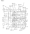
- FIG. 3 is a block diagram showing the pitch control device 1.
- the pitch control device 1 shown in FIG. 3 is disposed inside the hub 103, for example.
- the pitch control device 1 includes a plurality of (in this embodiment, three) induction motors 11 (11a, 11b, 11c), a plurality of (in this embodiment, three) batteries 12 (12a, 12b, 12c), a plurality of (in this embodiment, three) motor controllers 13 (13a, 13b, 13c), a plurality of (in this embodiment, three) encoders 14 (14a, 14b, 14c), a plurality of (in this embodiment, three) battery remaining power detectors 15 (15a, 15b, 15c), and so on.
- the pitch control device 1 includes, as lines (wires) and switches for the electricity supply system, a plurality of (in this embodiment, three) normal drive lines 16 (16a, 16b, 16c), a plurality of (in this embodiment, three) direct drive lines 17 (17a, 17b, 17c), a plurality of (in this embodiment, three) normal drive switches 18 (18a, 18b, 18c), a plurality of (in this embodiment, three) direct drive switches (19a, 19b, 19c), a common direct drive line 20, a direct power source switch 21, a plurality of (in this embodiment, three) main power source lines 22 (22a, 22b, 22c), a common main power source line 23, a plurality of (in this embodiment, three) independent drive switches 24 (24a, 24b, 24c), and so on.
- a plurality of (in this embodiment, three) normal drive lines 16 (16a, 16b, 16c)
- Each of the three induction motors 11 constitutes an electric motor in the present embodiment that is coupled to the pitch drive device 108 for changing the pitch angle of each of the three blades 104 (104a, 104b, 104c).
- the induction motors 11 are installed so as to be able to output the driving force for changing the pitch angle of the blades 104.
- the induction motor 11a is provided so as to correspond to the blade 104a
- the induction motor 11b is provided so as to correspond to the blade 104b
- the induction motor 11c is provided so as to correspond to the blade 104c.
- the three batteries 12 (12a, 12b, 12c) are provided so as to be able to apply electricity to the respective induction motors 11 (11a, 11b, 11c) via the motor controllers 13, which will be described later.
- the battery 12a, the battery 12b, and the battery 12c are configured to be able to apply electricity to the induction motor 11a, the induction motor 11b, and the induction motor 11c, respectively.
- the batteries 12 (12a, 12b, 12c) are provided so as to correspond to the respective motor controllers 13 (13a, 13b, 13c).
- the electricity from a main power source 111 is supplied to the batteries 12 (12a, 12b, 12c) respectively via the common main power source line 23, the main power source lines 22 (22a, 22b, 22c), and the motor controllers 13 (13a, 13b, 13c) that will be described later, and electricity is thereby stored in the batteries 12 (12a, 12b, 12c).
- Each battery 12 (12a, 12b, 12c) constitutes an electricity accumulator in the present embodiment.
- the present embodiment will be described, taking, as an example, a configuration in which the batteries 12 (12a, 12b, 12c) are provided as the electricity accumulators, a configuration in which electricity accumulators in the form other than the batteries are provided may alternatively employed.
- a configuration in which a condenser or a capacitor such as an EDLC (Electric double-layer capacitor) is used as the electricity accumulator may also be employed.
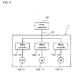
- FIG. 4 is a block diagram showing the motor controllers 13 (13a, 13b, 13c) and the pitch controller 50, which is a computer superordinate thereto.
- the pitch controller 50 shown in FIG. 4 includes a CPU (Central Processing Unit), a memory, and so on, which are not shown in FIG. 4 , and is configured to be able to communicate with the motor controllers 13 (13a, 13b, 13c) via a communication line 51.
- CPU Central Processing Unit
- the pitch controller 50 determines the target pitch angle of the blades 104 (104a, 104b, 104c) such that rotation is properly performed in accordance with the wind pressure exerted on the blades 104, based on a result of a wind pressure detection performed by a wind pressure sensor (not shown). Based on the target pitch angle, the pitch controller 50 transmits a control signal for pitch control for changing the pitch angle of the blades 104 to the motor controllers 13 (13a, 13b, 13c) via the communication line 51.
- the three motor controls 13 (13a, 13b, 13c) shown in FIGS. 3 and 4 are provided, and installed so as to correspond to the respective induction motors 11 (i.e., so as to correspond to the respective blades 104).
- the motor controller 13a is provided so as to correspond to the blade 104a and the induction motor 11a
- the motor controller 13b is provided so as to correspond to the blade 104b and the induction motor 11b
- the motor controller 13c is provided so as to correspond to the blade 104c and the induction motor 11c.
- Each motor controller 13 (13a, 13b, 13c) includes a CPU (Central Processing Unit), an interface circuit, a power module portion that controls electricity supplied to the induction motor 11, a memory, and so on, which are not shown in the drawings.
- the motor controllers 13 are connected via the communication line 51 to the pitch controller 50 so as to be able to communicate therewith, and are also connected to the induction motors 11 and the batteries 12 so as to be able to communicate therewith.
- the motor controllers 13 are configured to be connected to the main power source 111, which is an external power source for supplying electricity during normal operation that is a state where no power failure, or no equipment fault or abnormality in the electricity supply system is occurring, and thus electricity is supplied to the motor controllers 13.
- the power module portion for example, is configured as an inverter circuit that controls electricity supplied to the induction motors 11 and rotation of the induction motors 11 by converting direct-current power supplied from the main power source 111 to alternating-current power.
- the main power source 111 is configured as, for example the electricity supply system that supplies direct-current power that is electricity from an external alternating-current power source rectified by a rectifier (not shown) into direct-current power.
- the external alternating-current power source that supplies the electricity to the main power source 111 via the rectifier may be, for example, a direct power source 112, which will be described later, or may be an external alternating-current power source constituted independently from the direct power source 112.
- the motor controllers 13 are configured to control storage of electricity from the main power source 111 in the batteries 12 and discharge of electricity stored in the batteries 12 to the induction motors 11. That is, the motor controller 13a controls storage and discharge of electricity in and from the battery 12a, the motor controller 13b controls storage and discharge of electricity in and from the battery 12b, and the motor controller 13c controls storage and discharge of electricity in and from the battery 12c. Further, the motor controllers 13 receive the above-mentioned control signal transmitted from the pitch controller 13 via the communication line 51, and control the operation of the induction motors 11 based on the control signal. In other words, based on the control signal from the pitch controller 13, the motor controller 13a controls the induction motor 11a; the motor controller 13b controls the induction motor 11b, and the motor controller 13c controls the induction motor 11c.
- the motor controllers 13 are configured to continue the pitch control for the blades 104 by controlling the induction motors 11 with the electricity supplied from the batteries 12, based on the control signal from the pitch controller 13. Further, the motor controllers 13 are also configured to be able to control the pitch angle of the blades 104 with the electricity of the batteries 12 such that the pitch angle is changed in a direction in which the wind pressure exerted on the blades 104 is reduced, based on a result of detection by the battery remaining power detectors 15, which will be described later.
- the motor controllers 13 are configured so as to be able to rotate the induction motors 11 with the electricity of the batteries 12 such that feathering is performed for changing the pitch angle in a direction in which the wind pressure exerted on the blades 104 is reduced. Note that if the aforementioned rotational operation of the induction motors 11 is performed under the control of the motor controllers 13, each induction motor 11 is stopped at a predetermined rotational angle position (feather position) that brings about a feathering state.
- the pitch angle of the blade 104 is fixed in a state where the blade surface of the blade portion 105b of each blade 104 is parallel to the wind direction such that substantially no wind pressure is exerted on the blade 104.
- the motor controllers 13 receipt of the control signal from the pitch controller 50 and transmission of a command signal to the induction motors 11 and the batteries 12 are performed via the interface circuits.
- the memories in the motor controllers 13 store a program for performing processing of the motor controllers 13 for controlling storage and discharge of electricity in and from the batteries 12 and the operation of the induction motors 11, and the program is read and executed by the CPU.
- the three encoders 14 (14a, 14b, 14c) shown in FIG. 3 are provided so as to correspond to the respective induction motors 11 (i.e., so as to correspond to the respective blades 14), and are configured to be able to detect the rotation number of the induction motors 11 (and so as to be able to also detect the rotational angle and the rotational speed of the induction motors 11).
- the encoder 14a is provided so as to detect the rotation number of the induction motor 11a for driving the blade 104a
- the encoder 14b is provided so as to detect the rotation number of the induction motor 11b for driving the blade 104b
- the encoder 14c is provided so as to detect the rotation number of the induction motor 11c for driving the blade 104c.
- each encoder 14 constitutes a pitch angle detector in the present embodiment that detects the pitch angle of the blade 104 (104a, 104b, 104c) based on a result of detection of the rotation number of the induction motor 11.
- each induction motor 11 is stopped at the predetermined rotational angle position (feather position) that brings about the feathering state, based on the result of detection by the encoder 14 serving as the pitch angle detector.
- the pitch angle detector may be configured as a limit switch that is disposed at a feather position and detects the pitch angle that brings about this feather position is also possible.
- the pitch angle detector is configured as a gear unit that is disposed in the vicinity of the shaft portion 105a of each blade 104 and is meshed with a gear formed on the shaft portion 105a to detect the pitch angle that brings about the feather position.
- the three battery remaining power detectors 15 (15a, 15b, 15c) shown in FIG. 3 are provided, as mentioned above, and are installed in the respective batteries 12.
- Each battery remaining power detector 15 is configured as a detector that detects a remaining power of the battery 12.
- the battery remaining power detector 15a is installed in the battery 12a and detects the remaining power therein
- the battery remaining power detector 15b is installed in the battery 12b and detects the remaining power therein
- the battery remaining power detector 15c is installed in the battery 12c and detects the remaining power therein.
- each battery remaining power detector 15 (15a, 15b, 15c) constitutes an electricity accumulator operation monitoring portion in the present embodiment that monitors an operational state of the battery 12 by detecting the remaining power of the battery 12.
- each battery remaining power detector 15 also constitutes an electricity accumulator remaining power detector in the present embodiment.
- a condenser remaining power detector or a capacitor remaining power detector is provided as the electricity accumulator operation monitoring portion and the electricity accumulator remaining power detector.
- control for changing the pitch angle of the blades 104 in a direction in which the wind pressure is reduced is performed to perform feathering, based on a result of monitoring by the electricity accumulator operation monitoring portion, that is, a result of detection by the battery remaining power detectors 15.
- the pitch control device 1 is configured such that this feathering control is performed when the remaining power detected by any of the battery remaining power detector 15 is smaller than or equal to a predetermined value, while the motor controllers 13 are continuing the pitch control with the electricity supplied from the batteries 12 at the time of a loss of the electricity supply capability of the main power source 111.
- feathering control is performed by the motor controllers 13 controlling the induction motors 11 based on the result of detection by the battery remaining power detectors 15.
- the three normal drive lines 16 (16a, 16b, 16c) shown in FIG. 3 are provided, as mentioned above, so as to correspond to the respective induction motors 11 (i.e., so as to correspond to the respective blades 104).
- the normal drive line 16a is provided as an electricity supply line that connects the motor controller 13a to the induction motor 11a and is able to supply electricity to the induction motor 11a during normal operation.
- the normal drive line 16b is provided as an electricity supply line that connects the motor controller 13b to the induction motor 11b and is able to supply electricity to the induction motor 11b during normal operation.
- the normal drive line 16c is provided as an electricity supply line that connects the motor controller 13c to the induction motor 11c and is able to supply electricity to the induction motor 11c during normal operation.
- the three direct drive lines 17 (17a, 17b, 17c) shown in FIG. 3 are provided, as mentioned above, so as to correspond to the respective induction motors 11 (i.e., so as to correspond to the respective blades 104).
- the direct drive line 17a is provided as an electricity supply line that connects the induction motor 11a to the direct power source 112, which is provided as an external alternating-current power source different from the main power source 111, via the normal drive line 16a, and that is able to supply alternating-current power from the direct-current power source 112 to the induction motor 11a to drive the induction motor 11a.
- the direct drive line 17b is provided as an electricity supply line that connects the direct power source 112 to the induction motor 11b via the normal drive line 16b, and is able to supply the alternating-current power from the direct power source 112 to the induction motor 11b to drive the induction motor 11b.
- the direct drive line 17c is provided as an electricity supply line that connects the direct power source 112 to the induction motor 11c via the normal drive line 16c, and is able to supply the alternating-current power from the direct power source 112 to the induction motor 11c to drive the induction motor 11c.
- the three normal drive switches 18 (18a, 18b, 18c) shown in FIG. 3 are provided, as mentioned above, so as to correspond to the respective normal drive lines 16 (i.e., so as to correspond to the respective blades 104).
- the normal drive switch 18a is provided as a switch on the normal drive line 16a that is able to switch between a state where the motor controller 13a and the induction motor 11a are connected to each other and a state where they are disconnected from each other.
- the normal drive switch 18b is provided as a switch on the normal drive line 16b that is able to switch between a state where the motor controller 13b and the induction motor 11b are connected to each other and a state where they are disconnected from each other.
- the normal drive switch 18c is provided as a switch on the normal drive line 16c that is able to switch between a state where the motor controller 13c and the induction motor 11c are connected to each other and a state where they are disconnected from each other. Note that these normal drive switches 18 (18a, 18b, 18c) are configured to be able to switch between the connected state (on state) and the disconnected state (off state) based on a command signal from any of the motor controllers 13 (13a, 13b, 13c), for example.
- the three direct drive switches 19 (19a, 19b, 19c) shown in FIG. 3 are provided as mentioned above, so as to correspond to the respective direct drive lines 17 (i.e., so as to correspond to the respective blades 104).
- the direct drive switch 19a is provided as a switch on the direct drive line 17a that is able to switch between a state where the direct power source 112 and the induction motor 11a are connected to each other and a state where they are disconnected from each other.
- the direct drive switch 19b is provided as a switch on the direct drive line 17b that is able to switch between a state where the direct power source 112 and the induction motor 11b are connected from each other and a state where they are disconnected from each other.
- the direct drive switch 19c is provided as a switch on the direct drive line 17c that is able to switch between a state where the direct power source 112 and the induction motor 11c are connected to each other and a state where they are disconnected from each other.
- these direct drive switches 19 (19a, 19b, 19c) are configured to be able to switch between the connected state (on state) and the disconnected state (off state) based on a command signal from any of the motor controllers 13 (13a, 13b, 13c), for example.
- the common direct drive line 20 shown in FIG. 3 is provided as an electricity supply line that connects the direct power source 112 to the direct drive lines 17 (117a, 17b, 17c).
- the direct drive lines 17 (17a, 17b, 17c) are configured to be connected to the same direct power source 112 via the common direct drive line 20 that is provided to be shared by the direct drive lines 17.
- the common direct drive line 20 is provided with the direct power source switch 21.
- the direct power source switch 21 is configured as a switch capable of switching between a state where the direct power source 112 and the direct drive lines 17 (17a, 17b, 17c) are connected to each other and a state where they are disconnected from each other.
- the direct power source switch 21 is configured to be able to switch between the connected state (on state) and the disconnected state (off state), based on a command signal from at least any of the motor controllers 13, for example.
- the three main power source lines 22 (22a, 22b, 22c) shown in FIG. 3 are provided, as mentioned above, as electricity supply lines that are connected to the respective motor controllers 13 so as to supply electricity from the main power source 111 to the motor controllers 13 (13a, 13b, 13c).
- the main power source line 22a is configured to be connected to the motor controller 13a and supply electricity thereto.
- the main power source line 22b is configured to be connected to the motor controller 13b and supply electricity thereto.
- the main power source line 22c is configured to be connected to the motor controller 13c and supply electricity thereto.
- the common main power source line 23 shown in FIG. 3 is provided as an electricity supply line that connects the main power source 111 to the main power source lines 22 (22a, 22b, 22c).
- the main power source lines 22 (22a, 22b, 22c) are configured to be connected to the same main power source 111 via the common main power source line 23 that is provided to be shared by the main power source lines 22.
- the three independent drive switches 24 (24a, 24b, 24c) shown in FIG. 3 are provided, as mentioned above, on the respective normal drive lines 16 (16a, 16b, 16c).
- the independent drive switch 24a is provided as a switch on the normal drive line 16a between the normal drive switch 18a and the induction motor 11a that is able to switch between a state where the normal drive switch 18a and the induction motor 11a are connected to each other and a state where they are disconnected from each other.
- the direct drive line 17a is connected to the normal drive line 16a between the normal drive switch 18a and the independent drive switch 24a.
- the independent drive switch 24b is provided as a switch on the normal drive line 16b between the normal drive switch 18b and the induction motor 11b that is able to switch between a state where the normal drive switch 18b and the induction motor 11b are connected to each other and a state where they are disconnected from each other.
- the direct drive line 17b is connected to the normal drive line 16b between the normal drive switch 18b and the independent drive switch 24b.
- the independent drive switch 24c is provided as a switch on the normal drive line 16c between the normal drive switch 18c and the induction motor 11c that is able to switch between a state where the normal drive switch 18c and the induction motor 11c are connected to each other and a state where they are disconnected from each other.
- the direct drive line 17c is connected to the normal drive line 16c between the normal drive switch 18c and the independent drive switch 24c.
- these independent drive switches 24 24a, 24b, 24c are configured to be able to switch between the connected state (on state) and the disconnected state (off state) based on a command signal from any of the motor controllers 13 (13a, 13b, 13c), for example.
- the direct power source switch 21 is turned off, and the normal drive switches 18 and the independent drive switches 24 are in the on state.
- Electricity from the main power source 111 is supplied to the induction motors 11 via the common main power source line 23, the main power source lines 22, the motor controllers 13, and the normal drive lines 16.
- the motor controllers 13 control the induction motors 13 with electricity supplied from the main power source 111 based on a control signal from the pitch controller 50, and the pitch drive devices 108 are thereby driven.
- the pitch control for the blades 104 is performed by the pitch control device 1 such that the pitch angle is appropriate for the wind pressure exerted on the blades 104.
- Feathering is performed if it is detected by any of the battery remaining power detectors 15 that the remaining power is smaller than or equal to a predetermined value while the pitch control is being continued with the electricity from the batteries 12 due to occurrence of a loss of the electricity supply capability of the main power source 111.
- the motor controllers 13 control the induction motors 11 with the electricity supplied from the batteries 12, and feathering is performed for changing the pitch angle in a direction in which the wind pressure exerted on the blades 104 is reduced.
- the windmill 100 is prevented from being damaged due to an abnormal increase in the rotational speed of the blades 104 and the hub 103.
- feathering is performed if it is detected by the battery remaining power detectors 15 that the remaining power is smaller than or equal to a predetermined value. Therefore, it is possible to readily implement the configuration in which feathering is performed before feathering becomes impossible due to a lack of the electricity of the batteries 12.
- feathering is performed with the electricity of the direct power source 112 if it is detected that the remaining power detected by the battery remaining power detectors 15 rapidly or suddenly becomes smaller than or equal to a predetermined lower limit value, which is further smaller than the aforementioned predetermined value, while the pitch control is being continued with the electricity from the batteries 12 due to occurrence of a loss of the electricity supply capability of the main power source 111.
- feathering is performed not with the electricity of the batteries 12 but with the electricity of the direct power source 112 if the capability of the batteries 12 has degraded or an abnormality has occurred in the batteries 12, causing the remaining power to rapidly or suddenly fall below a remaining power state in which feathering can be performed with the electricity of the batteries 12.
- the normal drive switches 18 are turned to the off state, and then the direct power source switch 21 and the direct drive switches 19 are turned to the on state. Note that the on state of the independent drive switches 24 is maintained.
- feathering is performed for changing the pitch angle in a direction in which the wind pressure exerted on the blades 104 is reduced, with the electricity of the direct power source 112. It is possible to stop, at a predetermined position, the feathering operation for changing the pitch angle of the blades 104 to complete feathering, based on a result of detection by the encoders 14 each serving as the pitch angle detector. Accordingly, with the pitch control device 1, feathering can be performed also with the electricity of the direct power source 112. Therefore, it is possible to perform feathering even if the capability of the batteries 12 has degraded or an abnormality has occurred in the batteries 12 while the pitch control is being performed with the electricity of the batteries 12.
- the pitch control device 1 if an abnormality has occurred in any of the motor controllers 13, the pitch control is performed for the blade 104 corresponding to the abnormal controller that is the motor controller 13 in which the abnormality has occurred, by a normal controller that is the motor controller 13 which is normal and different from the abnormal controller. For example, if an abnormality has occurred in the motor controller 13a (abnormal controller) during normal operation, or while the pitch control is being performed with electricity of the batteries 12, the pitch control for the blade 104a is performed by the motor controller 13b or the motor controller 13c that is a normal controller.
- the pitch control for the blade 104b or 104c is performed by one of the two motor controllers 13 other than the motor controller 13b or 13c in which the abnormality occurred. Further, if an abnormality has occurred in two motor controllers (e.g., 13a and 13b), the pitch controller for the blades (104a and 104b in this case) is performed by the remaining motor controller (e.g., 13c) that is a normal controller. Note that if the pitch control for the blade 104 corresponding to an abnormal controller is performed by a normal controller, the pitch control for the blade 104 corresponding to the normal controller is also performed simultaneously by the normal controller.
- the off state of the direct power source switch 21 is maintained, while the on state of the normal drive switch 18b corresponding to the motor controller 13b that is a normal controller and the blade 104b is maintained.
- the direct drive switch 19b is turned to the on state.
- the normal drive switch 18a corresponding to the motor controller 13a that is an abnormal controller and the blade 104a is turned to the off state, and the direct drive switch 19a is turned to the on state. Note that the on state of the independent drive switches 24a and 24b is maintained.
- a windmill pitch control device 1 capable of performing feathering, and continuing to generate electricity even at the time of a loss of the electricity supply capability of the main power source 111.
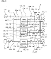
- FIG. 5 is a block diagram showing a windmill pitch control device 2 (hereinafter, also referred to simply as a "pitch control device 2") according to the second embodiment.
- the pitch control device 2 shown in FIG. 5 is applied to the windmill 100, as with the pitch control device 1 in the first embodiment.
- the pitch control device 2 is configured similarly to the first embodiment, and has the same components as those of the pitch control device1.
- the pitch control device 2 is different from the pitch control device 1 of the first embodiment on the point that it further has a main power source switch 25 and on a point concerning the configuration for transmitting a signal from the encoders 14 each serving as the pitch angle detector to the motor controllers 13.
- the description of the same configuration as that in the first embodiment will be omitted by using, or citing, the same symbols in the drawings, and only the configuration different from that in the first embodiment will be described.
- the common main power source line 23 in the pitch control device 2 is provided with the main power source switch 25.
- the main power source switch 25 is configured as a switch capable of switching between a state where the main power source 111 and the main power source lines 22 (22a, 22b, 22c) are connected to each other and a state where they are disconnected from each other.
- the direct power source switch 25 is configured to be able to switch between the connected state (on state) and the disconnected state (off state) based on a command signal from at least one of the motor controllers 13.
- each encoder (pitch angle detector) 14 is connected to all motor controllers 13 so as to be able to transmit a detection result signal to all those motor controllers 13.
- the encoder 14a is connected to the motor controller 13a via a pitch angle detection signal line 26 so as to be able to transmit a detection result signal to the motor controller 13a
- the motor controller 13b is connected to the motor controller 13b via a pitch angle detection signal line 27 so as to be able to transmit a detection result signal to the motor controller 13b
- a pitch angle detection signal line 28 so as to be able to transmit a detection result signal to the motor controller 13c.
- each of the encoders 14b and 14c is connected to the motor controller 13a via the pitch angle detection signal line 26 (not shown) so as to be able to transmit a detection result signal to the motor controller 13a, is connected to the motor controller 13b via a pitch angle detection signal line 27 (not shown) so as to be able to transmit a detection result signal to the motor controller 13b, and is connected to the motor controller 13c via a pitch angle detection signal line 28 (not shown) so as to be able to transmit a detection result signal to the motor controller 13c.
- the pitch control device 2 operates similarly to the pitch control device 1 in the first embodiment during normal operation in which no power failure or no equipment fault or abnormality is occurring in the main power source 111.
- the motor controllers 13 control the induction motors 11 with electricity supplied from the main power source 111, based on a control signal from the pitch controller 50, and thus the pitch control for the blades 104 is performed.
- the pitch control device 2 also operates similarly to the pitch control device 1 in the first embodiment if power failure, or equipment fault or abnormality has occurred in the main power source 111 and a loss of the electricity supply capability of the main power source 111 has occurred accordingly.
- the motor controllers 13 control the induction motors 11 with the electricity supplied from the batteries 12 to continue the pitch control, based on a control signal from the pitch controller 50.
- electricity generation is continued even at the time of a loss of the electricity supply capability of the main power source 111.
- feathering is performed as in the first embodiment.
- the windmill 100 is prevented from being damaged due to an abnormal increase in the rotational speed of the blades 104 and the hub 103.
- feathering can be performed before feathering becomes impossible due to a lack of the electricity of the batteries 12.
- feathering is performed as in the first embodiment if the capability of the batteries 12 has degraded or an abnormality of the batteries 12 has occurred such that the remaining power therein rapidly or suddenly falls below a remaining power state in which feathering can be performed with the electricity of the batteries 12 while the pitch control is being continued with the electricity from the batteries 12 due to occurrence of a loss of the electricity supply capability of the main power source 111.
- predetermined switches (18, 19, 21) are switched, and feathering is performed not with electricity of the batteries 12 but with electricity of the direct power source 112. Therefore, it is possible to perform feathering even if the capability of the batteries 12 has degraded or an abnormality of the batteries 12 has occurred while the pitch control is being performed with the electricity of the batteries 12.
- the windmill pitch control device 2 capable of performing feathering, and of continuing to generate electricity even at the time of a loss of the electricity supply capability of the main power source 111, as in the first embodiment.
- the common main power source line 23 in the pitch control device 2 is provided with the main power source switch 25. Therefore, even if the remaining power of a battery (any one of 12a, 12b, 12c) corresponding to any one of the motor controllers (13a, 13b, 13c) has become low while the pitch control is being continued with the electricity from the batteries 12 due to occurrence of a loss of the electricity supply capability of the main power source 111, it can be supplemented by the electricity of the batteries 12 corresponding to the other motor controllers 13.
- the main power source switch 25 is turned to the off state based on a command signal from the motor controller 13a.
- electricity can be supplied to the battery 12a corresponding to the motor controller 13a from the batteries (12b, 12c) corresponding to the motor controllers (13b, 13c) via the main power source lines (22a, 22b, 22c) and the common main power source line 23.
- the pitch control device 2 when, in the pitch control device 2, an abnormality occurred in any of the motor controllers 13, the pitch control is independently performed for the blades 104 by a normal controller that is the motor controller 13 which is normal and different from an abnormal controller that is the motor controller 13 in which the abnormality occurred.
- the result of detection by each of the encoders 14 corresponding to the respective blades 104 is transmitted to all motor controllers 13, and the independent drive switches 24 are provided between the electric motors 11 and both the points of the direct drive lines 17 located on the normal drive lines 16 and the normal drive switches 18.
- the pitch control for the blade 104 corresponding to the normal controller and the pitch control for the blade 104 corresponding to the abnormal controller are independently performed by the normal controller, as a result of the independent drive switch 24 corresponding to the normal controller and the independent drive switch 24 corresponding to the abnormal controller being switched.
- the off state of the direct power source switch 21 is maintained, while the on state of the normal drive switch 18b corresponding to the motor controller 13b that is a normal controller and the blade 104b is maintained. Then, the direct drive switch 19b is turned to the on state. Meanwhile, the normal drive switch 18a corresponding to the motor controller 13a that is the abnormal controller and the blade 104a is turned to the off state, and the direct drive switch 19a is turned to the on state. Then, the on state and the off state of the independent drive switches 24a and 24b are alternately switched based on a command signal from the motor controller 13b.
- the on state and the off state of the independent drive switches 24a and 24b are alternately switched such that the independent drive switch 24b is set to the off state when the independent drive switch 24a is in the on state, and the independent drive switch 24b is set to the on state when the independent drive switch 24a is in the off state.
- the pitch control for the respective blades 104 can be independently continued to generate electricity, by the other normal motor controllers 13.
- the electricity accumulator operation monitoring portion may be provided in a casing that is separate from the electricity accumulator, or may be configured to monitor an operational state other than the remaining power of the electricity accumulator.
- the present embodiments have been described, taking, as an example, the configuration in which feathering is controlled based on a command signal from the motor controllers, this need not be the case.
- a configuration is also possible in which a controller other than the motor controllers is further provided, and feathering is controlled by this controller.
- the first and second embodiments have been described, taking, as an example, a configuration in which the electric motors connected to the pitch drive devices are configured as the induction motors, this need not be the case.
- a configuration in which the electric motors are configured as brush direct-current motors, brushless motors, synchronous motors, or the like is also possible.
- the configuration of the power module portions in the main power source, the direct power source, and the motor controllers will be changed in accordance with the configuration of the electric motors.
- direct-current motors are used as the electric motors, it is desired to consider problems such as a decrease in the maintainability of the electric motors, an increase in the outside diameter thereof, and a decrease in the responsiveness thereof.
- the brushless motors are used as the electric motors, it is desired to consider the problem in that an additional drive controller is necessary, while such electric motors have good maintainability.
- the present invention can be widely applied to windmill pitch control devices that include an electricity accumulator capable of applying electricity to electric motors connected to a pitch drive device for changing the pitch angle of each blade of a windmill that is provided rotatably on a main shaft portion of the windmill, and that is able to control the pitch angle of the blade with electricity of the electricity accumulator such that the pitch angle is changed in a direction in which the wind pressure exerted on the blade is reduced.
- an electricity accumulator capable of applying electricity to electric motors connected to a pitch drive device for changing the pitch angle of each blade of a windmill that is provided rotatably on a main shaft portion of the windmill, and that is able to control the pitch angle of the blade with electricity of the electricity accumulator such that the pitch angle is changed in a direction in which the wind pressure exerted on the blade is reduced.
Landscapes
- Engineering & Computer Science (AREA)
- Life Sciences & Earth Sciences (AREA)
- Sustainable Development (AREA)
- Sustainable Energy (AREA)
- Chemical & Material Sciences (AREA)
- Combustion & Propulsion (AREA)
- Mechanical Engineering (AREA)
- General Engineering & Computer Science (AREA)
- Physics & Mathematics (AREA)
- Fluid Mechanics (AREA)
- Wind Motors (AREA)
Abstract
Description
- The present invention relates to a windmill pitch control device that includes an electricity accumulator capable of applying electricity to an electric motor connected to a pitch drive device for changing the pitch angle of a blade of a windmill that is provided rotatably on a main shaft portion of the windmill, and that is able to control the pitch angle of the blade with electricity of the electricity accumulator such that the pitch angle is changed in a direction in which the wind pressure exerted on the blade is reduced.
- A windmill may be provided with a windmill pitch control device that controls the pitch angle of blades provided rotatably on a main shaft portion of the windmill. As such a windmill pitch control device, a windmill pitch control device is known that includes a battery serving as an electricity accumulator capable of applying electricity to an electric motor coupled to a pitch drive device for changing the pitch angle of a blade of a windmill, and that controls the pitch angle of the blade with the electricity of the battery so as to change the pitch angle in a direction in which the wind pressure exerted on the blade is reduced (see Patent Document 1). In the windmill pitch control device disclosed in
Patent Document 1, during normal operation, the electric motor coupled to the pitch drive device is driven as a result of electricity being supplied to the electric motor from an external power source via an electricity controller (221), which serves as a motor controller that controls supply of electricity to the electric motor coupled to the pitch drive device to control operation of the electric motor. Note that the external power source is provided as a main power source that is a power source for supplying electricity during normal operation. In the case of power failure, on the other hand, the source of electricity to the electric motor coupled to the pitch drive device is switched from the main power source to a battery (220) by the electricity controller. Then, the pitch angle of the blade is controlled such that the pitch angle is changed in a direction in which the wind pressure exerted on the blade is reduced (such that feathering of the blade is performed). This is aimed at preventing the windmill from being damaged by an abnormal increase in the rotational speed of the blades and the main shaft portion. - Patent Document 1:
JP2003-222070A FIG. 3 ) - The windmill pitch control device disclosed in
Patent Document 1 is configured such that in the case where a loss of an electricity supply capability of the main power source has occurred due to occurrence of power failure, feathering is performed for changing the pitch angle in a direction in which the wind pressure exerted on the blade is reduced, by supplying electricity from the battery. However, in this windmill pitch control device, feathering is performed as mentioned above at the time of a loss of the electricity supply capability of the main power source, and therefore, pitch control for changing the pitch angle of the blade cannot be performed. Accordingly, the windmill pitch control device has a problem of inability to continue to generate electricity because the pitch control necessary for electricity generation cannot be performed at the time of a loss of the electricity supply capability of the main power source. - In light of the foregoing situation, it is an object of the present invention to provide a windmill pitch control device capable of performing feathering, and continuing to generate electricity even at the time of a loss of the electricity supply capability of the main power source.
- A windmill pitch control device according to a first aspect of the present invention for achieving the above-stated object is a windmill pitch control device that includes an electricity accumulator capable of applying electricity to an electric motor coupled to a pitch drive device for changing a pitch angle of a blade of a windmill that is provided rotatably on a main shaft portion of the windmill, and that is able to control the pitch angle of the blade with the electricity of the electricity accumulator such that the pitch angle is changed in a direction in which a wind pressure exerted on the blade is reduced, the windmill pitch control device comprising: a motor controller that controls storage and discharge of the electricity in and from the electricity accumulator, and controls the electric motor based on a control signal for pitch control for changing the pitch angle of the blade from a pitch controller that transmits the control signal; and an electricity accumulator operation monitoring portion that monitors an operational state of the electricity accumulator, wherein the motor controller is connected to a main power source that is a power source for supplying electricity during normal operation such that the electricity is supplied to the motor controller, and at the time of a loss of an electricity supply capability of the main power source, the motor controller controls the electric motor with the electricity supplied from the electricity accumulator and continues the pitch control, based on the control signal, and control for changing the pitch angle of the blade in a direction in which the wind pressure is reduced is performed based on a result of monitoring by the electricity accumulator operation monitoring portion.
- According to the first aspect of the present invention, at the time of a loss of the electricity supply capability of the main power source, the motor controller controls the electric motor with the electricity supplied from the electricity accumulator to continue the pitch control, based on the control signal from the pitch controller. Therefore, with the windmill pitch control device according to the present invention, it is possible to continue to generate electricity even at the time of loss of the power supply capability of the main power source. Furthermore, with the windmill pitch control device according to the present invention, feathering is performed for changing the pitch angle in a direction in which the wind pressure exerted on the blade is reduced, based on the result of monitoring by the electricity accumulator operation monitoring portion that monitors the operational state of the electricity accumulator. Thus, the windmill is prevented from being damaged due to an abnormal increase in the rotational speed of the blade and the main shaft portion.
- Accordingly, according to the present invention, it is possible to provide a windmill pitch control device capable of performing feathering, and continuing to generate electricity even at the time of a loss of the electricity supply capability of the main power source.
- A windmill pitch control device according to a second aspect of the present invention is the windmill pitch control device of the first aspect, wherein a plurality of the motor controllers are provided in one-to-one correspondence to a plurality of the blades provided on the windmill, and if an abnormality has occurred in any of the motor controllers, the pitch control for the blade corresponding to an abnormal controller that is the motor controller in which the abnormality has occurred is performed by a normal controller that is the motor controller which is normal and different from the abnormal controller.
- According to the second aspect of the present invention, if an abnormality has occurred in any of the motor controllers, the pitch control for the blade corresponding to the abnormal controller is performed by the normal controller that is different from the abnormal controller. Therefore, it is possible to continue to generate electricity not only at the time of a loss of the electricity supply capability of the main power source, but also in the case where an abnormality has occurred in any of the motor controllers.
- A windmill pitch control device according to a third aspect of the present invention is the windmill pitch control device of the first aspect, wherein the electric motor is provided as an induction motor, and the windmill pitch control device further comprises: a normal drive line that connects the motor controller to the electric motor, and is able to supply the electricity to the electric motor during the normal operation; a direct drive line that connects directly, or via the normal drive line, the electric motor to a direct power source provided as an alternating-current power source which is different from the main power source, and that is able to supply the electricity from the direct power source to the electric motor and drive the electric motor; a normal-drive switch that is provided on the normal drive line and is able to switch between a state where the motor controller and the electric motor are connected to each other and a state where they are disconnected from each other; a direct drive switch that is provided on the direct drive line and is able to switch between a state where the direct power source and the electric motor are connected to each other and a state where they are disconnected from each other; and a pitch angle detector that detects the pitch angle of the blade.
- According to the third aspect of the present invention, the normal drive line and the normal drive switch provided on this normal drive line, the direct drive line that connects the alternating-current direct power source to the induction motor and the direct drive switch provided on this direct drive line, and the pitch angle detector are provided. Therefore, at the time of a loss of the electricity supply capability of the main power source, it is possible to perform, with the electricity of the direct power source, feathering for changing the pitch angle in a direction in which the wind pressure is exerted on the blade, by turning the direct drive switch to the on state after turning the normal drive switch to the off state. It is then possible to stop, at a predetermined position, the feathering operation in which the pitch angle of the blade is changed and to complete feathering, based on a result of detection by the pitch angle detector. Accordingly, feathering can be performed also with the electricity of the direct power source, and it is therefore possible to perform feathering even if the capability of the electricity accumulator has degraded or an abnormality has occurred in the electricity accumulator while the pitch control is being performed with the electricity of the electricity accumulator.
- A windmill pitch control device according to a fourth aspect of the present invention is the windmill pitch control device of the third aspect, wherein a plurality of the motor controllers, a plurality of the pitch angle detectors, a plurality of the direct drive lines, a plurality of the direct drive switches, a plurality of the normal drive lines, and a plurality of the normal drive switches are provided in one-to-one correspondence to a plurality of the blades provided on the windmill, the direct drive lines are connected to the same direct power source via a common direct drive line provided to be shared by the direct drive lines, and the common direct drive line is provided with a direct power source switch capable of switching between a state where the direct power source and the direct drive lines are connected to each other and a state where they are disconnected from each other.
- According to the fourth aspect of the present invention, the motor controllers, the pitch angle detectors, the direct drive lines, the direct drive switches, the normal drive lines, and the normal drive switches are provided so as to correspond to the respective blades. The direct drive lines are connected to the same direct power source via the common direct drive line, and the direct power source switch is provided on this common direct drive line. Therefore, a circuit can be configured in which the direct power source switch is in the off state and the normal drive switch and the direct drive switch corresponding to one blade are in the on state, while the normal drive switch corresponding to another blade is in the off state, and the direct drive switch corresponding to this blade is in the on state. Thus, the motor controller corresponding to one blade can control the electric motor for changing the pitch angle of another blade. Consequently, in the windmill pitch control device in which the feathering can be performed with the electricity of the direct power source at the time of a loss of the electricity supply capability of the main power source, even if an abnormality has occurred in any of the motor controllers, it is possible to continue the pitch control with another normal motor controller, and thus to continue to generate electricity.
- A windmill pitch control device according to a fifth aspect of the present invention is the windmill pitch control device of the fourth aspect, wherein each of the normal drive lines is provided with an independent drive switch between the normal drive switches and the electric motors, the independent drive switch being able to switch between a state where the normal drive switches and the electric motors are connected to each other and a state where they are disconnected from each other, the direct drive lines are connected to the respective normal drive lines between the normal drive switches and the independent drive switches, each of the pitch angle detectors is connected to all of the motor controllers so as to be able to transmit a detection result signal thereto, and if an abnormality has occurred in any of the motor controllers, the pitch control for the blade corresponding to an abnormal controller that is the motor controller in which the abnormality has occurred and the pitch control for the blade corresponding to a normal controller that is the motor controller which is normal and different from the abnormal controller are independently performed by the normal controller as a result of the independent drive switch corresponding to the normal controller and the independent drive switch corresponding to the abnormal controller being switched.
- According to the fifth aspect of the present invention, the result of detection by the pitch angle detector corresponding to each blade is transmitted to all of the motor controllers, and the independent drive switch is provided between the electric motor and both a point of the direct drive line located on the normal drive line and the normal drive switch. If an abnormality has occurred in any of the motor controllers, the pitch control for the blade corresponding to the normal controller, which is different from the abnormal controller, and the pitch control for the blade corresponding to the abnormal controller are independently performed by the normal controller, as a result of the independent drive switch being switched. Consequently, in the windmill pitch control device capable of performing feathering with the electricity of the direct power source at the time of a loss of the electricity supply capability of the main power source, even if an abnormality has occurred in any of the motor controllers, it is possible to continue independent pitch control for each blade with another normal motor controller, and thus to continue to generate electricity.
- A windmill pitch control device according to a sixth aspect of the present invention is the windmill pitch control device of any one of the first to fifth aspects, wherein a plurality of the electricity accumulators are provided in one-to-one correspondence to a plurality of the motor controllers, a plurality of main power source lines connected to the respective motor controllers are provided so as to supply electricity from the main power source thereto, the main power source lines are connected to the same main power source via a common main power source line provided to be shared by the main power source lines, and the common main power source line is provided with a main power source switch capable of switching between a state where the main power source and the main power source lines are connected to each other and a state where they are disconnected from each other.
- According to the sixth aspect of the present invention, the electricity accumulator and the main power source line that supplies electricity from the main power source are provided so as to correspond to each motor controller. The main power source lines are connected to the same main power source via the common main power source line, and the main power source switch is provided on this common main power source line. Therefore, while the main power source switch is in the off state, electricity can be supplied from the electricity accumulator corresponding to one motor controller to the electricity accumulator corresponding to another motor controller via the main power source lines and the common main power source line (or only via both main power source lines if the electricity accumulator can be connected without via the common main power source line). Accordingly, even if the remaining power of the electricity accumulator corresponding to any of the motor controller has become low, this electricity accumulator can be supplemented by the power of the electricity accumulator corresponding to another motor controller. Furthermore, even if the remaining power of the electricity accumulator corresponding to any of the motor controllers has become low, this electricity accumulator can be supplemented by the power of another electricity accumulator, and it is therefore possible to maintain independent pitch control for each blade.
- A windmill pitch control device according to a seventh aspect of the present invention is the windmill pitch control device of any one of the first to sixth aspects, wherein an electricity accumulator remaining power detector that detects a remaining power of the electricity accumulator is provided as the electricity accumulator operation monitoring portion, and if the remaining power detected by the electricity accumulator remaining power detector is smaller than or equal to a predetermined value while the motor controller is continuing the pitch control with the electricity supplied from the electricity accumulator, the pitch angle of the blade is controlled such that the pitch angle is changed in a direction in which the wind pressure exerted on the blade is reduced.
- According to the seventh aspect of the present invention, the electricity accumulator remaining power detector is provided as the electricity accumulator operation monitoring portion, and feathering is performed if the remaining power detected by the electricity accumulator remaining power detector is smaller than or equal to the predetermined value while the pitch control is being continued with the electricity of the electricity accumulator. Therefore, a configuration can be readily implemented in which feathering is performed before feathering becomes impossible due to a lack of the power of the electricity accumulator.
- According to the present invention, it is possible to provide a windmill pitch control device capable of performing feathering, and continuing to generate electricity even at the time of a loss of the electricity supply capability of the main power source.
-
-
FIG. 1 is a perspective view of a windmill to which a windmill pitch control device according to a first embodiment of the present invention is applied. -
FIG. 2 is an enlarged cross-sectional view of a portion of the windmill shown inFIG. 1 where a blade is attached to a hub. -
FIG. 3 is a block diagram showing a windmill pitch control device according to the first embodiment of the present invention. -
FIG. 4 is a block diagram showing a motor controller in the pitch control device shown inFIG. 3 and a pitch controller that is superordinate thereto. -
FIG. 5 is a block diagram showing a windmill pitch control device according to a second embodiment of the present invention. - Hereinafter, embodiments of the present invention will be described with reference to the drawings. The embodiments of the present invention can be widely applied to windmill pitch control devices that include an electricity accumulator capable of applying electricity to an electric motor coupled to a pitch drive device for changing the pitch angle of blades of a windmill that are provided rotatably on a main shaft portion of the windmill, and that is able to control the pitch angle of the blades with the electricity of the electricity accumulator such that the pitch angle is changed in a direction in which the wind pressure exerted on the blades is reduced.
-
FIG. 1 is a perspective view of awindmill 100 to which a windmill pitch control device 1 (hereinafter, also referred to simply as a "pitch control device 1") according to a first embodiment of the present invention is applied. As shown inFIG. 1 , thewindmill 100 includes atower 101, anacelle 102, a hub (main shaft portion) 103,blades 104, and so on. Thetower 101 is installed, extending vertically upward from the ground. Thenacelle 102 is rotatably disposed on thetower 101 so as to be turned around in a horizontal plane by a yaw drive device (not shown). A power transmission shaft, an electricity generator, and so on, which are not shown in the drawings, are disposed inside thenacelle 102. Thehub 103, which constitutes the main shaft portion in the present embodiment, is coupled to the aforementioned power transmission shaft and is rotatably provided on thenacelle 102. A plurality of (in the present embodiment, three) blades 104 (104a, 104b, 104c) are attached to thehub 103, extending radially at equal angle intervals. Each blade 104 (104a, 104b, 104c) is constituted by a hollowcylindrical shaft portion 105a that is attached to thehub 103, and ablade portion 105b for receiving wind. -
FIG. 2 is an enlarged cross-sectional view showing a portion where eachblade 104 is attached to thehub 103, together with apitch drive device 108 and aninduction motor 11 serving as a motor for driving thepitch drive device 108. Thehub 103 has openings formed in portions to which theblades 104 are attached, and theblades 104 are disposed so as to face those openings at the ends of theirshaft portions 105a. Eachblade 104 is supported at itsshaft portion 105a on thehub 104 via abearing 106, and is rotatably provided on thehub 103. Aring gear 107 having internal teeth disposed on its inner circumferential side is provided at the end of theshaft portion 105a on the side attached to the hub 103 (inFIG. 2 , the internal teeth of thering gear 107 are not shown). Thering gear 107 is disposed such that its shaft center coincides with the shaft center of theshaft portion 105a, and is configured so as to mesh with anoutput pinion 109 of thepitch drive device 108, which is configured as a speed reducer. - Three
pitch drive devices 108 are provided, respectively corresponding to the three blades 104 (104a, 104b, 104c), and eachpitch drive device 108 is attached via abracket 110 to the inside of an opening portion of thehub 103 to which theblade 104 is attached. Thepitch drive devices 108 are each coupled to theinduction motor 11, reduce the speed of the driving force input from theinduction motor 11 and output the driving force to thepinion 109, thereby causing theblade 104 to rotate about its shaft center with respect to thehub 103, together with thering gear 107 that meshes with thepinion 109. Thepitch drive devices 108 are thereby configured to change the pitch angle of the blades 104 (104a, 104b, 104c). - Next, the
pitch control device 1 according to the first embodiment of the prensent invention will be described.FIG. 3 is a block diagram showing thepitch control device 1. Thepitch control device 1 shown inFIG. 3 is disposed inside thehub 103, for example. Thepitch control device 1 includes a plurality of (in this embodiment, three) induction motors 11 (11a, 11b, 11c), a plurality of (in this embodiment, three) batteries 12 (12a, 12b, 12c), a plurality of (in this embodiment, three) motor controllers 13 (13a, 13b, 13c), a plurality of (in this embodiment, three) encoders 14 (14a, 14b, 14c), a plurality of (in this embodiment, three) battery remaining power detectors 15 (15a, 15b, 15c), and so on. In addition to the aforementioned components, thepitch control device 1 includes, as lines (wires) and switches for the electricity supply system, a plurality of (in this embodiment, three) normal drive lines 16 (16a, 16b, 16c), a plurality of (in this embodiment, three) direct drive lines 17 (17a, 17b, 17c), a plurality of (in this embodiment, three) normal drive switches 18 (18a, 18b, 18c), a plurality of (in this embodiment, three) direct drive switches (19a, 19b, 19c), a common direct drive line 20, a directpower source switch 21, a plurality of (in this embodiment, three) main power source lines 22 (22a, 22b, 22c), a common mainpower source line 23, a plurality of (in this embodiment, three) independent drive switches 24 (24a, 24b, 24c), and so on. - Each of the three induction motors 11 (11a, 11b, 11c) constitutes an electric motor in the present embodiment that is coupled to the
pitch drive device 108 for changing the pitch angle of each of the three blades 104 (104a, 104b, 104c). Theinduction motors 11 are installed so as to be able to output the driving force for changing the pitch angle of theblades 104. Note that theinduction motor 11a is provided so as to correspond to theblade 104a, theinduction motor 11b is provided so as to correspond to theblade 104b, and theinduction motor 11c is provided so as to correspond to theblade 104c. - The three batteries 12 (12a, 12b, 12c) are provided so as to be able to apply electricity to the respective induction motors 11 (11a, 11b, 11c) via the
motor controllers 13, which will be described later. In other words, thebattery 12a, thebattery 12b, and thebattery 12c are configured to be able to apply electricity to theinduction motor 11a, theinduction motor 11b, and theinduction motor 11c, respectively. The batteries 12 (12a, 12b, 12c) are provided so as to correspond to the respective motor controllers 13 (13a, 13b, 13c). The electricity from amain power source 111 is supplied to the batteries 12 (12a, 12b, 12c) respectively via the common mainpower source line 23, the main power source lines 22 (22a, 22b, 22c), and the motor controllers 13 (13a, 13b, 13c) that will be described later, and electricity is thereby stored in the batteries 12 (12a, 12b, 12c). Each battery 12 (12a, 12b, 12c) constitutes an electricity accumulator in the present embodiment. Although the present embodiment will be described, taking, as an example, a configuration in which the batteries 12 (12a, 12b, 12c) are provided as the electricity accumulators, a configuration in which electricity accumulators in the form other than the batteries are provided may alternatively employed. For example, a configuration in which a condenser or a capacitor such as an EDLC (Electric double-layer capacitor) is used as the electricity accumulator may also be employed. - Here, a description will be given of a
pitch controller 50 that transmits a control signal to the motor controllers 13 (13a, 13b, 13c), which will be described later.FIG. 4 is a block diagram showing the motor controllers 13 (13a, 13b, 13c) and thepitch controller 50, which is a computer superordinate thereto. InFIG. 4 , components of thepitch control device 1 other than themotor controllers 13 and theinduction motors 11 are omitted. Thepitch controller 50 shown inFIG. 4 includes a CPU (Central Processing Unit), a memory, and so on, which are not shown inFIG. 4 , and is configured to be able to communicate with the motor controllers 13 (13a, 13b, 13c) via acommunication line 51. Thepitch controller 50 determines the target pitch angle of the blades 104 (104a, 104b, 104c) such that rotation is properly performed in accordance with the wind pressure exerted on theblades 104, based on a result of a wind pressure detection performed by a wind pressure sensor (not shown). Based on the target pitch angle, thepitch controller 50 transmits a control signal for pitch control for changing the pitch angle of theblades 104 to the motor controllers 13 (13a, 13b, 13c) via thecommunication line 51. - As mentioned above, the three motor controls 13 (13a, 13b, 13c) shown in
FIGS. 3 and4 are provided, and installed so as to correspond to the respective induction motors 11 (i.e., so as to correspond to the respective blades 104). In other words, themotor controller 13a is provided so as to correspond to theblade 104a and theinduction motor 11a, themotor controller 13b is provided so as to correspond to theblade 104b and theinduction motor 11b, and themotor controller 13c is provided so as to correspond to theblade 104c and theinduction motor 11c. Each motor controller 13 (13a, 13b, 13c) includes a CPU (Central Processing Unit), an interface circuit, a power module portion that controls electricity supplied to theinduction motor 11, a memory, and so on, which are not shown in the drawings. Themotor controllers 13 are connected via thecommunication line 51 to thepitch controller 50 so as to be able to communicate therewith, and are also connected to theinduction motors 11 and thebatteries 12 so as to be able to communicate therewith. - Further, the
motor controllers 13 are configured to be connected to themain power source 111, which is an external power source for supplying electricity during normal operation that is a state where no power failure, or no equipment fault or abnormality in the electricity supply system is occurring, and thus electricity is supplied to themotor controllers 13. In eachmotor controller 13, the power module portion, for example, is configured as an inverter circuit that controls electricity supplied to theinduction motors 11 and rotation of theinduction motors 11 by converting direct-current power supplied from themain power source 111 to alternating-current power. In the present embodiment, themain power source 111 is configured as, for example the electricity supply system that supplies direct-current power that is electricity from an external alternating-current power source rectified by a rectifier (not shown) into direct-current power. The external alternating-current power source that supplies the electricity to themain power source 111 via the rectifier may be, for example, adirect power source 112, which will be described later, or may be an external alternating-current power source constituted independently from thedirect power source 112. - Further, the
motor controllers 13 are configured to control storage of electricity from themain power source 111 in thebatteries 12 and discharge of electricity stored in thebatteries 12 to theinduction motors 11. That is, themotor controller 13a controls storage and discharge of electricity in and from thebattery 12a, themotor controller 13b controls storage and discharge of electricity in and from thebattery 12b, and themotor controller 13c controls storage and discharge of electricity in and from thebattery 12c. Further, themotor controllers 13 receive the above-mentioned control signal transmitted from thepitch controller 13 via thecommunication line 51, and control the operation of theinduction motors 11 based on the control signal. In other words, based on the control signal from thepitch controller 13, themotor controller 13a controls theinduction motor 11a; themotor controller 13b controls theinduction motor 11b, and themotor controller 13c controls theinduction motor 11c. - In addition, at the time of a loss of the electricity supply capability of the
main power source 111 due to occurrence of power failure, equipment fault, or the like, themotor controllers 13 are configured to continue the pitch control for theblades 104 by controlling theinduction motors 11 with the electricity supplied from thebatteries 12, based on the control signal from thepitch controller 13. Further, themotor controllers 13 are also configured to be able to control the pitch angle of theblades 104 with the electricity of thebatteries 12 such that the pitch angle is changed in a direction in which the wind pressure exerted on theblades 104 is reduced, based on a result of detection by the battery remainingpower detectors 15, which will be described later. In other words, themotor controllers 13 are configured so as to be able to rotate theinduction motors 11 with the electricity of thebatteries 12 such that feathering is performed for changing the pitch angle in a direction in which the wind pressure exerted on theblades 104 is reduced. Note that if the aforementioned rotational operation of theinduction motors 11 is performed under the control of themotor controllers 13, eachinduction motor 11 is stopped at a predetermined rotational angle position (feather position) that brings about a feathering state. In the state where feathering has been performed (the state where eachinduction motor 11 has been stopped at the feather position), the pitch angle of theblade 104 is fixed in a state where the blade surface of theblade portion 105b of eachblade 104 is parallel to the wind direction such that substantially no wind pressure is exerted on theblade 104. - Note that in the
motor controllers 13, receipt of the control signal from thepitch controller 50 and transmission of a command signal to theinduction motors 11 and thebatteries 12 are performed via the interface circuits. The memories in themotor controllers 13 store a program for performing processing of themotor controllers 13 for controlling storage and discharge of electricity in and from thebatteries 12 and the operation of theinduction motors 11, and the program is read and executed by the CPU. - As mentioned above, the three encoders 14 (14a, 14b, 14c) shown in
FIG. 3 are provided so as to correspond to the respective induction motors 11 (i.e., so as to correspond to the respective blades 14), and are configured to be able to detect the rotation number of the induction motors 11 (and so as to be able to also detect the rotational angle and the rotational speed of the induction motors 11). In other words, theencoder 14a is provided so as to detect the rotation number of theinduction motor 11a for driving theblade 104a, theencoder 14b is provided so as to detect the rotation number of theinduction motor 11b for driving theblade 104b, and the encoder 14c is provided so as to detect the rotation number of theinduction motor 11c for driving theblade 104c. - Further, each encoder 14 (14a, 14b, 14c) constitutes a pitch angle detector in the present embodiment that detects the pitch angle of the blade 104 (104a, 104b, 104c) based on a result of detection of the rotation number of the
induction motor 11. When the aforementioned feathering is performed, eachinduction motor 11 is stopped at the predetermined rotational angle position (feather position) that brings about the feathering state, based on the result of detection by theencoder 14 serving as the pitch angle detector. Although the present embodiment has been described, taking, as an example, a configuration in which the pitch angle detector is configured as theencoder 14, this need not be the case. For example, the pitch angle detector may be configured as a limit switch that is disposed at a feather position and detects the pitch angle that brings about this feather position is also possible. Another configuration is also possible in which the pitch angle detector is configured as a gear unit that is disposed in the vicinity of theshaft portion 105a of eachblade 104 and is meshed with a gear formed on theshaft portion 105a to detect the pitch angle that brings about the feather position. - The three battery remaining power detectors 15 (15a, 15b, 15c) shown in
FIG. 3 are provided, as mentioned above, and are installed in therespective batteries 12. Each battery remainingpower detector 15 is configured as a detector that detects a remaining power of thebattery 12. In other words, the battery remainingpower detector 15a is installed in thebattery 12a and detects the remaining power therein, the battery remainingpower detector 15b is installed in thebattery 12b and detects the remaining power therein, and the battery remainingpower detector 15c is installed in thebattery 12c and detects the remaining power therein. Furthermore, each battery remaining power detector 15 (15a, 15b, 15c) constitutes an electricity accumulator operation monitoring portion in the present embodiment that monitors an operational state of thebattery 12 by detecting the remaining power of thebattery 12. Furthermore, each battery remaining power detector 15 (15a, 15b, 15c) also constitutes an electricity accumulator remaining power detector in the present embodiment. Note that in the configuration in which a condenser or a capacitor is provided as the electricity accumulator, a condenser remaining power detector or a capacitor remaining power detector is provided as the electricity accumulator operation monitoring portion and the electricity accumulator remaining power detector. - In the
pitch control device 1, control for changing the pitch angle of theblades 104 in a direction in which the wind pressure is reduced is performed to perform feathering, based on a result of monitoring by the electricity accumulator operation monitoring portion, that is, a result of detection by the battery remainingpower detectors 15. Thepitch control device 1 is configured such that this feathering control is performed when the remaining power detected by any of the battery remainingpower detector 15 is smaller than or equal to a predetermined value, while themotor controllers 13 are continuing the pitch control with the electricity supplied from thebatteries 12 at the time of a loss of the electricity supply capability of themain power source 111. In other words, feathering control is performed by themotor controllers 13 controlling theinduction motors 11 based on the result of detection by the battery remainingpower detectors 15. - The three normal drive lines 16 (16a, 16b, 16c) shown in
FIG. 3 are provided, as mentioned above, so as to correspond to the respective induction motors 11 (i.e., so as to correspond to the respective blades 104). Thenormal drive line 16a is provided as an electricity supply line that connects themotor controller 13a to theinduction motor 11a and is able to supply electricity to theinduction motor 11a during normal operation. Thenormal drive line 16b is provided as an electricity supply line that connects themotor controller 13b to theinduction motor 11b and is able to supply electricity to theinduction motor 11b during normal operation. Thenormal drive line 16c is provided as an electricity supply line that connects themotor controller 13c to theinduction motor 11c and is able to supply electricity to theinduction motor 11c during normal operation. - The three direct drive lines 17 (17a, 17b, 17c) shown in
FIG. 3 are provided, as mentioned above, so as to correspond to the respective induction motors 11 (i.e., so as to correspond to the respective blades 104). Thedirect drive line 17a is provided as an electricity supply line that connects theinduction motor 11a to thedirect power source 112, which is provided as an external alternating-current power source different from themain power source 111, via thenormal drive line 16a, and that is able to supply alternating-current power from the direct-current power source 112 to theinduction motor 11a to drive theinduction motor 11a. Thedirect drive line 17b is provided as an electricity supply line that connects thedirect power source 112 to theinduction motor 11b via thenormal drive line 16b, and is able to supply the alternating-current power from thedirect power source 112 to theinduction motor 11b to drive theinduction motor 11b. Thedirect drive line 17c is provided as an electricity supply line that connects thedirect power source 112 to theinduction motor 11c via thenormal drive line 16c, and is able to supply the alternating-current power from thedirect power source 112 to theinduction motor 11c to drive theinduction motor 11c. - The three normal drive switches 18 (18a, 18b, 18c) shown in
FIG. 3 are provided, as mentioned above, so as to correspond to the respective normal drive lines 16 (i.e., so as to correspond to the respective blades 104). Thenormal drive switch 18a is provided as a switch on thenormal drive line 16a that is able to switch between a state where themotor controller 13a and theinduction motor 11a are connected to each other and a state where they are disconnected from each other. Thenormal drive switch 18b is provided as a switch on thenormal drive line 16b that is able to switch between a state where themotor controller 13b and theinduction motor 11b are connected to each other and a state where they are disconnected from each other. Thenormal drive switch 18c is provided as a switch on thenormal drive line 16c that is able to switch between a state where themotor controller 13c and theinduction motor 11c are connected to each other and a state where they are disconnected from each other. Note that these normal drive switches 18 (18a, 18b, 18c) are configured to be able to switch between the connected state (on state) and the disconnected state (off state) based on a command signal from any of the motor controllers 13 (13a, 13b, 13c), for example. - The three direct drive switches 19 (19a, 19b, 19c) shown in
FIG. 3 are provided as mentioned above, so as to correspond to the respective direct drive lines 17 (i.e., so as to correspond to the respective blades 104). Thedirect drive switch 19a is provided as a switch on thedirect drive line 17a that is able to switch between a state where thedirect power source 112 and theinduction motor 11a are connected to each other and a state where they are disconnected from each other. Thedirect drive switch 19b is provided as a switch on thedirect drive line 17b that is able to switch between a state where thedirect power source 112 and theinduction motor 11b are connected from each other and a state where they are disconnected from each other. Thedirect drive switch 19c is provided as a switch on thedirect drive line 17c that is able to switch between a state where thedirect power source 112 and theinduction motor 11c are connected to each other and a state where they are disconnected from each other. Note that these direct drive switches 19 (19a, 19b, 19c) are configured to be able to switch between the connected state (on state) and the disconnected state (off state) based on a command signal from any of the motor controllers 13 (13a, 13b, 13c), for example. - The common direct drive line 20 shown in
FIG. 3 is provided as an electricity supply line that connects thedirect power source 112 to the direct drive lines 17 (117a, 17b, 17c). Thus the direct drive lines 17 (17a, 17b, 17c) are configured to be connected to the samedirect power source 112 via the common direct drive line 20 that is provided to be shared by the direct drive lines 17. Further, the common direct drive line 20 is provided with the directpower source switch 21. The directpower source switch 21 is configured as a switch capable of switching between a state where thedirect power source 112 and the direct drive lines 17 (17a, 17b, 17c) are connected to each other and a state where they are disconnected from each other. Note that the directpower source switch 21 is configured to be able to switch between the connected state (on state) and the disconnected state (off state), based on a command signal from at least any of themotor controllers 13, for example. - The three main power source lines 22 (22a, 22b, 22c) shown in
FIG. 3 are provided, as mentioned above, as electricity supply lines that are connected to therespective motor controllers 13 so as to supply electricity from themain power source 111 to the motor controllers 13 (13a, 13b, 13c). In other words, the mainpower source line 22a is configured to be connected to themotor controller 13a and supply electricity thereto. The mainpower source line 22b is configured to be connected to themotor controller 13b and supply electricity thereto. The mainpower source line 22c is configured to be connected to themotor controller 13c and supply electricity thereto. - The common main
power source line 23 shown inFIG. 3 is provided as an electricity supply line that connects themain power source 111 to the main power source lines 22 (22a, 22b, 22c). Thus the main power source lines 22 (22a, 22b, 22c) are configured to be connected to the samemain power source 111 via the common mainpower source line 23 that is provided to be shared by the main power source lines 22. - The three independent drive switches 24 (24a, 24b, 24c) shown in
FIG. 3 are provided, as mentioned above, on the respective normal drive lines 16 (16a, 16b, 16c). Theindependent drive switch 24a is provided as a switch on thenormal drive line 16a between thenormal drive switch 18a and theinduction motor 11a that is able to switch between a state where thenormal drive switch 18a and theinduction motor 11a are connected to each other and a state where they are disconnected from each other. Thedirect drive line 17a is connected to thenormal drive line 16a between thenormal drive switch 18a and theindependent drive switch 24a. Theindependent drive switch 24b is provided as a switch on thenormal drive line 16b between thenormal drive switch 18b and theinduction motor 11b that is able to switch between a state where thenormal drive switch 18b and theinduction motor 11b are connected to each other and a state where they are disconnected from each other. Thedirect drive line 17b is connected to thenormal drive line 16b between thenormal drive switch 18b and theindependent drive switch 24b. Theindependent drive switch 24c is provided as a switch on thenormal drive line 16c between thenormal drive switch 18c and theinduction motor 11c that is able to switch between a state where thenormal drive switch 18c and theinduction motor 11c are connected to each other and a state where they are disconnected from each other. Thedirect drive line 17c is connected to thenormal drive line 16c between thenormal drive switch 18c and theindependent drive switch 24c. Note that these independent drive switches 24 (24a, 24b, 24c) are configured to be able to switch between the connected state (on state) and the disconnected state (off state) based on a command signal from any of the motor controllers 13 (13a, 13b, 13c), for example. - Next, the operation of the aforementioned
pitch control device 1 will be described. During normal operation in which no power failure or no equipment fault or abnormality is occurring in themain power source 111, the directpower source switch 21 is turned off, and the normal drive switches 18 and the independent drive switches 24 are in the on state. Electricity from themain power source 111 is supplied to theinduction motors 11 via the common mainpower source line 23, the main power source lines 22, themotor controllers 13, and the normal drive lines 16. Further, themotor controllers 13 control theinduction motors 13 with electricity supplied from themain power source 111 based on a control signal from thepitch controller 50, and thepitch drive devices 108 are thereby driven. Thus the pitch control for theblades 104 is performed by thepitch control device 1 such that the pitch angle is appropriate for the wind pressure exerted on theblades 104. - On the other hand, if power failure, or equipment fault or abnormality has occurred in the
main power source 111 and a loss of the electricity supply capability of themain power source 111 has occurred accordingly, electricity of thebatteries 12 is supplied to theinduction motors 11 via themotor controllers 13 and the normal drive lines 16. Then, themotor controllers 13 control theinduction motors 11 with electricity supplied from thebatteries 12 to continue the pitch control, based on a control signal from thepitch controller 50. Therefore, with thepitch control device 1, it is possible to continue to generate electricity even at the time of a loss of the electricity supply capability of themain power source 111. - Feathering is performed if it is detected by any of the battery remaining
power detectors 15 that the remaining power is smaller than or equal to a predetermined value while the pitch control is being continued with the electricity from thebatteries 12 due to occurrence of a loss of the electricity supply capability of themain power source 111. In other words, based on a result of monitoring by the battery remainingpower detectors 15 each serving as the electricity accumulator operation monitoring portion, themotor controllers 13 control theinduction motors 11 with the electricity supplied from thebatteries 12, and feathering is performed for changing the pitch angle in a direction in which the wind pressure exerted on theblades 104 is reduced. Thus, thewindmill 100 is prevented from being damaged due to an abnormal increase in the rotational speed of theblades 104 and thehub 103. Furthermore, with thepitch control device 1, feathering is performed if it is detected by the battery remainingpower detectors 15 that the remaining power is smaller than or equal to a predetermined value. Therefore, it is possible to readily implement the configuration in which feathering is performed before feathering becomes impossible due to a lack of the electricity of thebatteries 12. - Furthermore, with the
pitch control device 1, feathering is performed with the electricity of thedirect power source 112 if it is detected that the remaining power detected by the battery remainingpower detectors 15 rapidly or suddenly becomes smaller than or equal to a predetermined lower limit value, which is further smaller than the aforementioned predetermined value, while the pitch control is being continued with the electricity from thebatteries 12 due to occurrence of a loss of the electricity supply capability of themain power source 111. In other words, feathering is performed not with the electricity of thebatteries 12 but with the electricity of thedirect power source 112 if the capability of thebatteries 12 has degraded or an abnormality has occurred in thebatteries 12, causing the remaining power to rapidly or suddenly fall below a remaining power state in which feathering can be performed with the electricity of thebatteries 12. In this case, based on a command signal from themotor controllers 13, the normal drive switches 18 are turned to the off state, and then the directpower source switch 21 and the direct drive switches 19 are turned to the on state. Note that the on state of the independent drive switches 24 is maintained. - With the above-described configuration, feathering is performed for changing the pitch angle in a direction in which the wind pressure exerted on the
blades 104 is reduced, with the electricity of thedirect power source 112. It is possible to stop, at a predetermined position, the feathering operation for changing the pitch angle of theblades 104 to complete feathering, based on a result of detection by theencoders 14 each serving as the pitch angle detector. Accordingly, with thepitch control device 1, feathering can be performed also with the electricity of thedirect power source 112. Therefore, it is possible to perform feathering even if the capability of thebatteries 12 has degraded or an abnormality has occurred in thebatteries 12 while the pitch control is being performed with the electricity of thebatteries 12. - In the
pitch control device 1, if an abnormality has occurred in any of themotor controllers 13, the pitch control is performed for theblade 104 corresponding to the abnormal controller that is themotor controller 13 in which the abnormality has occurred, by a normal controller that is themotor controller 13 which is normal and different from the abnormal controller. For example, if an abnormality has occurred in themotor controller 13a (abnormal controller) during normal operation, or while the pitch control is being performed with electricity of thebatteries 12, the pitch control for theblade 104a is performed by themotor controller 13b or themotor controller 13c that is a normal controller. Similarly, if an abnormality has occurred in themotor controller blade motor controllers 13 other than themotor controller blade 104 corresponding to an abnormal controller is performed by a normal controller, the pitch control for theblade 104 corresponding to the normal controller is also performed simultaneously by the normal controller. - Here, the aforementioned case where the pitch control for the
blade 104 corresponding to an abnormal controller is performed by a normal controller in thepitch control device 1 will be described in further detail. The following description will be given, taking, an example, the case where an abnormality has occurred in themotor controller 13a and the pitch control for theblade 104a is performed by themotor controller 13b. The same description is applied to other cases, which will not be described accordingly. - In the aforementioned case, first, the off state of the direct
power source switch 21 is maintained, while the on state of thenormal drive switch 18b corresponding to themotor controller 13b that is a normal controller and theblade 104b is maintained. Thedirect drive switch 19b is turned to the on state. Meanwhile, thenormal drive switch 18a corresponding to themotor controller 13a that is an abnormal controller and theblade 104a is turned to the off state, and thedirect drive switch 19a is turned to the on state. Note that the on state of theindependent drive switches motor controller 13b to both theinduction motors normal drive line 16b, thenormal drive switch 18b and theindependent drive switch 24a, thedirect drive line 17b and thedirect drive switch 19b, the common direct drive line 20, thedirect drive line 17a and thedirect drive switch 19a, and thenormal drive line 16a and theindependent drive switch 24a. - As a result of the above configuration, with the
motor controller 14b that is the normal controller corresponding to oneblade 104b, it is possible to also control theinduction motor 11a for changing the pitch angle of anotherblade 104a corresponding to themotor controller 13a, which is the abnormal controller. Consequently, in thepitch control device 1 capable of performing feathering with electricity of thedirect power source 112 at the time of a loss of the electricity supply capability of themain power source 111, even if an abnormality has occurred in any of themotor controllers 13, it is possible to continue the pitch control with the othernormal motor controllers 13, and thus to continue to generate electricity. - As described above, according to the present invention, it is possible to provide a windmill
pitch control device 1 capable of performing feathering, and continuing to generate electricity even at the time of a loss of the electricity supply capability of themain power source 111. - Next, a second embodiment of the present invention will be discussed.
FIG. 5 is a block diagram showing a windmill pitch control device 2 (hereinafter, also referred to simply as a "pitch control device 2") according to the second embodiment. Thepitch control device 2 shown inFIG. 5 is applied to thewindmill 100, as with thepitch control device 1 in the first embodiment. Thepitch control device 2 is configured similarly to the first embodiment, and has the same components as those of the pitch control device1. However, thepitch control device 2 is different from thepitch control device 1 of the first embodiment on the point that it further has a mainpower source switch 25 and on a point concerning the configuration for transmitting a signal from theencoders 14 each serving as the pitch angle detector to themotor controllers 13. Hereinafter, the description of the same configuration as that in the first embodiment will be omitted by using, or citing, the same symbols in the drawings, and only the configuration different from that in the first embodiment will be described. - As shown in
FIG. 5 , the common mainpower source line 23 in thepitch control device 2 is provided with the mainpower source switch 25. The mainpower source switch 25 is configured as a switch capable of switching between a state where themain power source 111 and the main power source lines 22 (22a, 22b, 22c) are connected to each other and a state where they are disconnected from each other. For example, the directpower source switch 25 is configured to be able to switch between the connected state (on state) and the disconnected state (off state) based on a command signal from at least one of themotor controllers 13. - As shown in
FIG. 5 , in thepitch control device 2, each encoder (pitch angle detector) 14 is connected to allmotor controllers 13 so as to be able to transmit a detection result signal to all thosemotor controllers 13. In other words, theencoder 14a is connected to themotor controller 13a via a pitch angledetection signal line 26 so as to be able to transmit a detection result signal to themotor controller 13a, is connected to themotor controller 13b via a pitch angledetection signal line 27 so as to be able to transmit a detection result signal to themotor controller 13b, and is connected to themotor controller 13c via a pitch angledetection signal line 28 so as to be able to transmit a detection result signal to themotor controller 13c. Although not shown inFIG. 5 , similarly, each of theencoders 14b and 14c is connected to themotor controller 13a via the pitch angle detection signal line 26 (not shown) so as to be able to transmit a detection result signal to themotor controller 13a, is connected to themotor controller 13b via a pitch angle detection signal line 27 (not shown) so as to be able to transmit a detection result signal to themotor controller 13b, and is connected to themotor controller 13c via a pitch angle detection signal line 28 (not shown) so as to be able to transmit a detection result signal to themotor controller 13c. - Next, the operation of the aforementioned
pitch control device 2 will be described. Thepitch control device 2 operates similarly to thepitch control device 1 in the first embodiment during normal operation in which no power failure or no equipment fault or abnormality is occurring in themain power source 111. In other words, in this case, themotor controllers 13 control theinduction motors 11 with electricity supplied from themain power source 111, based on a control signal from thepitch controller 50, and thus the pitch control for theblades 104 is performed. - The
pitch control device 2 also operates similarly to thepitch control device 1 in the first embodiment if power failure, or equipment fault or abnormality has occurred in themain power source 111 and a loss of the electricity supply capability of themain power source 111 has occurred accordingly. In other words, in this case, themotor controllers 13 control theinduction motors 11 with the electricity supplied from thebatteries 12 to continue the pitch control, based on a control signal from thepitch controller 50. Thus, electricity generation is continued even at the time of a loss of the electricity supply capability of themain power source 111. - Further, if, in the
pitch control device 2, it is detected by any of the battery remainingpower detectors 15 that the remaining power is smaller than or equal to a predetermined value while the pitch control is being continued with the electricity from thebatteries 12 due to occurrence of a loss of the electricity supply capability of themain power source 111, feathering is performed as in the first embodiment. Thus, thewindmill 100 is prevented from being damaged due to an abnormal increase in the rotational speed of theblades 104 and thehub 103. Moreover, feathering can be performed before feathering becomes impossible due to a lack of the electricity of thebatteries 12. - In the
pitch control device 2, feathering is performed as in the first embodiment if the capability of thebatteries 12 has degraded or an abnormality of thebatteries 12 has occurred such that the remaining power therein rapidly or suddenly falls below a remaining power state in which feathering can be performed with the electricity of thebatteries 12 while the pitch control is being continued with the electricity from thebatteries 12 due to occurrence of a loss of the electricity supply capability of themain power source 111. In other words, as in the first embodiment, predetermined switches (18, 19, 21) are switched, and feathering is performed not with electricity of thebatteries 12 but with electricity of thedirect power source 112. Therefore, it is possible to perform feathering even if the capability of thebatteries 12 has degraded or an abnormality of thebatteries 12 has occurred while the pitch control is being performed with the electricity of thebatteries 12. - Accordingly, according to the present embodiment, it is possible to provide the windmill
pitch control device 2 capable of performing feathering, and of continuing to generate electricity even at the time of a loss of the electricity supply capability of themain power source 111, as in the first embodiment. - Meanwhile, unlike the
pitch control device 1 in the first embodiment, the common mainpower source line 23 in thepitch control device 2 is provided with the mainpower source switch 25. Therefore, even if the remaining power of a battery (any one of 12a, 12b, 12c) corresponding to any one of the motor controllers (13a, 13b, 13c) has become low while the pitch control is being continued with the electricity from thebatteries 12 due to occurrence of a loss of the electricity supply capability of themain power source 111, it can be supplemented by the electricity of thebatteries 12 corresponding to theother motor controllers 13. - For example, if the remaining power of the
battery 12a corresponding to themotor controller 13a has become low, the mainpower source switch 25 is turned to the off state based on a command signal from themotor controller 13a. Thus, electricity can be supplied to thebattery 12a corresponding to themotor controller 13a from the batteries (12b, 12c) corresponding to the motor controllers (13b, 13c) via the main power source lines (22a, 22b, 22c) and the common mainpower source line 23. In other words, even if the remaining power of thebattery 12a corresponding to themotor controller 13a has become low, it can be supplemented by the electricity of the batteries (12b, 12c) corresponding to the other motor controllers (13b, 13c). - Although the above description has been given, taking, as an example, the case where the remaining power of the
battery 12a corresponding to themotor controller 13a has become low, the same applies to the case where the remaining power of the batteries (12b, 12c) corresponding to the motor controllers (13b, 13c) has become low. With thepitch control device 2, even if the remaining power of thebattery 12 corresponding to any of themotor controllers 13 has become low, it can be supplemented by the electricity of theother batteries 12. Therefore, the independent pitch control for theblades 104 can be maintained. - Unlike the
pitch control device 1 in the first embodiment, when, in thepitch control device 2, an abnormality occurred in any of themotor controllers 13, the pitch control is independently performed for theblades 104 by a normal controller that is themotor controller 13 which is normal and different from an abnormal controller that is themotor controller 13 in which the abnormality occurred. In other words, in thepitch control device 2, the result of detection by each of theencoders 14 corresponding to therespective blades 104 is transmitted to allmotor controllers 13, and the independent drive switches 24 are provided between theelectric motors 11 and both the points of thedirect drive lines 17 located on thenormal drive lines 16 and the normal drive switches 18. If an abnormality has occurred in any of themotor controllers 13, the pitch control for theblade 104 corresponding to the normal controller and the pitch control for theblade 104 corresponding to the abnormal controller are independently performed by the normal controller, as a result of theindependent drive switch 24 corresponding to the normal controller and theindependent drive switch 24 corresponding to the abnormal controller being switched. - A specific example of the aforementioned configuration will be described, taking, as an example, the case where an abnormality has occurred in the
motor controller 13a during normal operation, or while the pitch control is being performed with electricity of thebatteries 12, and the pitch control for theblade 104a is performed by themotor controller 13b. - In this case, first, the off state of the direct
power source switch 21 is maintained, while the on state of thenormal drive switch 18b corresponding to themotor controller 13b that is a normal controller and theblade 104b is maintained. Then, thedirect drive switch 19b is turned to the on state. Meanwhile, thenormal drive switch 18a corresponding to themotor controller 13a that is the abnormal controller and theblade 104a is turned to the off state, and thedirect drive switch 19a is turned to the on state. Then, the on state and the off state of theindependent drive switches motor controller 13b. In other words, the on state and the off state of theindependent drive switches independent drive switch 24b is set to the off state when theindependent drive switch 24a is in the on state, and theindependent drive switch 24b is set to the on state when theindependent drive switch 24a is in the off state. - With the above configuration, electricity is supplied alternately to the
induction motors motor controller 13b that receives the detection result signal of the encoders (14a, 14b), and thus the pitch control for the respective blades (104a, 104b) is alternately performed. In other words, by themotor controller 13b that is the normal controller, the pitch control for theblade 104b corresponding to thismotor controller 13b as well as the pitch control for theblade 104a corresponding to themotor controller 13a that is the abnormal controller are independently performed as a result of the independent drive switches (24a, 24b) being switched. Note that the pitch control for therespective blades 104 is independently performed, not only in the case described above as an example, but also in other cases. Accordingly, according to the present embodiment, even if an abnormality has occurred in any of themotor controllers 13 in thepitch control device 2 capable of performing feathering with electricity of thedirect power source 112 at the time of a loss of the electricity supply capability of themain power source 111, the pitch control for therespective blades 104 can be independently continued to generate electricity, by the othernormal motor controllers 13. - Although the embodiments of the present invention have been described thus far, the present invention is not limited to the embodiments described above, and various modifications may be made within the scope recited in the claims. For example, the following modifications can be made for implementation.
- (1) Although the first and second embodiments have been described, taking, as an example, the configuration in which the electricity accumulator operation monitoring portion is configured as the electricity accumulator remaining power detector installed in the electricity accumulator, this need not be the case. In other words, the electricity accumulator operation monitoring portion may be provided in a casing that is separate from the electricity accumulator, or may be configured to monitor an operational state other than the remaining power of the electricity accumulator. Further, although the present embodiments have been described, taking, as an example, the configuration in which feathering is controlled based on a command signal from the motor controllers, this need not be the case. For example, a configuration is also possible in which a controller other than the motor controllers is further provided, and feathering is controlled by this controller.
- (2) Although the first and second embodiments have been described, taking, as an example, the configuration in which the electricity accumulators are provided so as to correspond to the respective motor controllers, this need not be the case. A configuration in which the electricity accumulators are installed separately from the motor controllers is also possible, or a configuration in which the electricity accumulators are configured as a single unitary electricity accumulator is also possible.
- (3) Although the first and second embodiments have been described, taking, as an example, the configuration in which the direct drive lines connect the direct power source to the electric motors via the normal drive lines, this need not be the case. A configuration in which the direct drive lines directly connect the direct power source to the electric motors is also possible.
- (4) Although the first and second embodiments have been described, taking, as an example, a configuration in which the electric motors connected to the pitch drive devices are configured as the induction motors, this need not be the case. For example, a configuration in which the electric motors are configured as brush direct-current motors, brushless motors, synchronous motors, or the like is also possible. In this case, the configuration of the power module portions in the main power source, the direct power source, and the motor controllers will be changed in accordance with the configuration of the electric motors. Note that if direct-current motors are used as the electric motors, it is desired to consider problems such as a decrease in the maintainability of the electric motors, an increase in the outside diameter thereof, and a decrease in the responsiveness thereof. Further, if the brushless motors are used as the electric motors, it is desired to consider the problem in that an additional drive controller is necessary, while such electric motors have good maintainability.
- The present invention can be widely applied to windmill pitch control devices that include an electricity accumulator capable of applying electricity to electric motors connected to a pitch drive device for changing the pitch angle of each blade of a windmill that is provided rotatably on a main shaft portion of the windmill, and that is able to control the pitch angle of the blade with electricity of the electricity accumulator such that the pitch angle is changed in a direction in which the wind pressure exerted on the blade is reduced.
-
- 1 Windmill pitch control device
- 11, 11a, 11b, 11c Induction motor (electric motor)
- 12, 12a, 12b, 12c Battery (electricity accumulator)
- 13, 13a, 13b, 13c Motor controller
- 15, 15a, 15b, 15c Battery remaining power detector (electricity accumulator operation monitoring portion, electricity accumulator remaining power detector)
- 100 Windmill
- 103 Hub (main shaft portion)
- 104 Blade
- 108 Pitch drive device
Claims (7)
- A windmill pitch control device that includes an electricity accumulator capable of applying electricity to an electric motor coupled to a pitch drive device for changing a pitch angle of a blade of a windmill that is provided rotatably on a main shaft portion of the windmill, and that is able to control the pitch angle of the blade with the electricity of the electricity accumulator such that the pitch angle is changed in a direction in which a wind pressure exerted on the blade is reduced, the windmill pitch control device comprising:a motor controller that controls storage and discharge of the electricity in and from the electricity accumulator, and controls the electric motor based on a control signal for pitch control for changing the pitch angle of the blade from a pitch controller that transmits the control signal; andan electricity accumulator operation monitoring portion that monitors an operational state of the electricity accumulator,wherein the motor controller is connected to a main power source that is a power source for supplying electricity during normal operation such that the electricity is supplied to the motor controller, and at the time of a loss of an electricity supply capability of the main power source, the motor controller controls the electric motor with the electricity supplied from the electricity accumulator and continues the pitch control, based on the control signal, andcontrol for changing the pitch angle of the blade in a direction in which the wind pressure is reduced is performed based on a result of monitoring by the electricity accumulator operation monitoring portion.
- The windmill pitch control device according to claim 1,
wherein a plurality of the motor controllers are provided in one-to-one correspondence to a plurality of the blades provided on the windmill, and
if an abnormality has occurred in any of the motor controllers, the pitch control for the blade corresponding to an abnormal controller that is the motor controller in which the abnormality has occurred is performed by a normal controller that is the motor controller which is normal and different from the abnormal controller. - The pitch control device according to claim 1,
wherein the electric motor is provided as an induction motor, and
the windmill pitch control device further comprises:a normal drive line that connects the motor controller to the electric motor, and is able to supply the electricity to the electric motor during the normal operation;a direct drive line that connects directly, or via the normal drive line, the electric motor to a direct power source provided as an alternating-current power source which is different from the main power source, and that is able to supply the electricity from the direct power source to the electric motor and drive the electric motor;a normal drive switch that is provided on the normal drive line and is able to switch between a state where the motor controller and the electric motor are connected to each other and a state where they are disconnected from each other;a direct drive switch that is provided on the direct drive line and is able to switch between a state where the direct power source and the electric motor are connected to each other and a state where they are disconnected from each other; anda pitch angle detector that detects the pitch angle of the blade. - The pitch control device according to claim 3,
wherein a plurality of the motor controllers, a plurality of the pitch angle detectors, a plurality of the direct drive lines, a plurality of the direct drive switches, a plurality of the normal drive lines, and a plurality of the normal drive switches are provided in one-to-one correspondence to a plurality of the blades provided on the windmill,
the direct drive lines are connected to the same direct power source via a common direct drive line provided to be shared by the direct drive lines, and
the common direct drive line is provided with a direct power source switch capable of switching between a state where the direct power source and the direct drive lines are connected to each other and a state where they are disconnected from each other. - The windmill pitch control device according to claim 4,
wherein each of the normal drive lines is provided with an independent drive switch between the normal drive switches and the electric motors, the independent drive switch being able to switch between a state where the normal drive switches and the electric motors are connected to each other and a state where they are disconnected from each other,
the direct drive lines are connected to the respective normal drive lines between the normal drive switches and the independent drive switches,
each of the pitch angle detectors is connected to all of the motor controllers so as to be able to transmit a detection result signal thereto, and
if an abnormality has occurred in any of the motor controllers, the pitch control for the blade corresponding to an abnormal controller that is the motor controller in which the abnormality has occurred and the pitch control for the blade corresponding to a normal controller that is the motor controller which is normal and different from the abnormal controller are independently performed by the normal controller as a result of the independent drive switch corresponding to the normal controller and the independent drive switch corresponding to the abnormal controller being switched. - The windmill pitch control device according to any one of claims 1 to 5,
wherein a plurality of the electricity accumulators are provided in one-to-one correspondence to a plurality of the motor controllers,
a plurality of main power source lines connected to the respective motor controllers are provided so as to supply electricity from the main power source thereto,
the main power source lines are connected to the same main power source via a common main power source line provided to be shared by the main power source lines, and
the common main power source line is provided with a main power source switch capable of switching between a state where the main power source and the main power source lines are connected to each other and a state where they are disconnected from each other. - The windmill pitch control device according to any one of claims 1 to 6,
wherein an electricity accumulator remaining power detector that detects a remaining power of the electricity accumulator is provided as the electricity accumulator operation monitoring portion, and
if the remaining power detected by the electricity accumulator remaining power detector is smaller than or equal to a predetermined value while the motor controller is continuing the pitch control with the electricity supplied from the electricity accumulator, the pitch angle of the blade is controlled such that the pitch angle is changed in a direction in which the wind pressure exerted on the blade is reduced.
Applications Claiming Priority (2)
| Application Number | Priority Date | Filing Date | Title |
|---|---|---|---|
| JP2010150946A JP5520715B2 (en) | 2010-07-01 | 2010-07-01 | Pitch control device for windmill |
| PCT/JP2011/064510 WO2012002265A1 (en) | 2010-07-01 | 2011-06-24 | Windmill pitch control device |
Publications (3)
| Publication Number | Publication Date |
|---|---|
| EP2589800A1 true EP2589800A1 (en) | 2013-05-08 |
| EP2589800A4 EP2589800A4 (en) | 2015-03-25 |
| EP2589800B1 EP2589800B1 (en) | 2017-06-14 |
Family
ID=45401982
Family Applications (1)
| Application Number | Title | Priority Date | Filing Date |
|---|---|---|---|
| EP11800730.1A Not-in-force EP2589800B1 (en) | 2010-07-01 | 2011-06-24 | Windmill pitch control device |
Country Status (6)
| Country | Link |
|---|---|
| EP (1) | EP2589800B1 (en) |
| JP (1) | JP5520715B2 (en) |
| CN (1) | CN103080539B (en) |
| DK (1) | DK2589800T3 (en) |
| ES (1) | ES2635380T3 (en) |
| WO (1) | WO2012002265A1 (en) |
Cited By (6)
| Publication number | Priority date | Publication date | Assignee | Title |
|---|---|---|---|---|
| WO2015055217A1 (en) * | 2013-10-18 | 2015-04-23 | Mita-Teknik A/S | System for pitch control |
| WO2017121697A1 (en) * | 2016-01-16 | 2017-07-20 | Ssb Wind Systems Gmbh & Co. Kg | Wind power installation |
| EP3222847A1 (en) * | 2016-03-21 | 2017-09-27 | General Electric Company | Wind pitch adjustment system |
| EP3521612A1 (en) * | 2018-01-31 | 2019-08-07 | Siemens Gamesa Renewable Energy A/S | Method for controlling the pitch angle of wind turbine blades |
| EP4092263A1 (en) * | 2021-05-18 | 2022-11-23 | Siemens Gamesa Renewable Energy A/S | Reducing seismic loads that act on a wind turbine |
| US11767821B2 (en) | 2021-11-29 | 2023-09-26 | General Electric Renovables Espana, S.L. | System and method for responding to a friction coefficient signal of a wind turbine |
Families Citing this family (13)
| Publication number | Priority date | Publication date | Assignee | Title |
|---|---|---|---|---|
| JPH0638869B2 (en) | 1990-01-31 | 1994-05-25 | 極東産機株式会社 | Curtain length sewing machine |
| JPH0639654Y2 (en) | 1991-01-30 | 1994-10-19 | 極東産機株式会社 | Sewing machine pleating device |
| JPH0683752B2 (en) | 1991-01-30 | 1994-10-26 | 極東産機株式会社 | Curtain pleating device for sewing machines |
| JP3184181B2 (en) | 1999-05-21 | 2001-07-09 | 中日本ジューキ株式会社 | Automatic curtain fold sewing machine |
| JP3184188B2 (en) | 1999-11-12 | 2001-07-09 | 中日本ジューキ株式会社 | Automatic curtain fold sewing machine |
| CN102709944B (en) * | 2012-05-24 | 2014-12-31 | 浙江运达风电股份有限公司 | Control method of low voltage through of wind driven generator set based on DGNR variable pitch system |
| US8916988B2 (en) * | 2012-10-23 | 2014-12-23 | General Electric Company | Systems and methods for use in operating power generation systems |
| CN103352798B (en) * | 2013-06-26 | 2015-07-15 | 国家电网公司 | Blade collection system and blade collection method of wind generation set |
| KR101466104B1 (en) * | 2013-11-11 | 2014-11-27 | 삼성중공업 주식회사 | System and method for pitch of wind power generator |
| JP2015140726A (en) * | 2014-01-29 | 2015-08-03 | ナブテスコ株式会社 | Pitch drive device |
| JP6921514B2 (en) * | 2016-12-07 | 2021-08-18 | ナブテスコ株式会社 | Windmill drive system and windmill |
| CN114962153A (en) * | 2022-06-28 | 2022-08-30 | 西安热工研究院有限公司 | A wind power DC pitch system based on brushless DC permanent magnet motor control system |
| CN117231417A (en) * | 2023-08-07 | 2023-12-15 | 国华(锡林郭勒)新能源有限公司 | Pitch circuit and fan |
Family Cites Families (10)
| Publication number | Priority date | Publication date | Assignee | Title |
|---|---|---|---|---|
| JP2003222070A (en) | 2002-01-30 | 2003-08-08 | Mitsubishi Heavy Ind Ltd | Windmill |
| US6921985B2 (en) * | 2003-01-24 | 2005-07-26 | General Electric Company | Low voltage ride through for wind turbine generators |
| JP4233400B2 (en) * | 2003-07-04 | 2009-03-04 | ナブテスコ株式会社 | Wind turbine blade pitch angle drive device |
| DE10338127C5 (en) * | 2003-08-15 | 2015-08-06 | Senvion Se | Wind turbine with a rotor |
| WO2005021962A1 (en) * | 2003-09-03 | 2005-03-10 | General Electric Company | Redundant blade pitch control system for a wind turbine and method for controlling a wind turbine |
| DE102004005169B3 (en) * | 2004-02-02 | 2005-11-03 | Repower Systems Ag | Rotor blade pitch control system for wind turbine generating electricity has DC supply for motor with parallel-wound and series-wound field coils with diode bypassing series field coil during braking |
| DE102005030709A1 (en) * | 2005-06-29 | 2007-01-04 | Bosch Rexroth Ag | Actuator and emergency energy supply device |
| WO2007132303A1 (en) * | 2006-05-13 | 2007-11-22 | Clipper Windpower Technology, Inc. | Wind turbine system with ac servo motor rotor blade pitch control, using super-capacitor energy storage |
| JP4365394B2 (en) * | 2006-09-20 | 2009-11-18 | 株式会社日立製作所 | Wind power generation system and operation method thereof |
| US7745948B2 (en) * | 2007-11-28 | 2010-06-29 | General Electric Company | Emergency pitch drive unit for a wind turbine |
-
2010
- 2010-07-01 JP JP2010150946A patent/JP5520715B2/en active Active
-
2011
- 2011-06-24 ES ES11800730.1T patent/ES2635380T3/en active Active
- 2011-06-24 DK DK11800730.1T patent/DK2589800T3/en active
- 2011-06-24 WO PCT/JP2011/064510 patent/WO2012002265A1/en not_active Ceased
- 2011-06-24 CN CN201180042471.3A patent/CN103080539B/en not_active Expired - Fee Related
- 2011-06-24 EP EP11800730.1A patent/EP2589800B1/en not_active Not-in-force
Cited By (13)
| Publication number | Priority date | Publication date | Assignee | Title |
|---|---|---|---|---|
| WO2015055217A1 (en) * | 2013-10-18 | 2015-04-23 | Mita-Teknik A/S | System for pitch control |
| US11009007B2 (en) | 2016-01-16 | 2021-05-18 | Nidec Ssb Wind Systems Gmbh | Wind power installation |
| WO2017121697A1 (en) * | 2016-01-16 | 2017-07-20 | Ssb Wind Systems Gmbh & Co. Kg | Wind power installation |
| AU2017201646B2 (en) * | 2016-03-21 | 2021-09-23 | General Electric Renovables España, S.L. | Wind pitch adjustment system |
| US10408191B2 (en) | 2016-03-21 | 2019-09-10 | General Electric Company | Wind pitch adjustment system |
| RU2727541C2 (en) * | 2016-03-21 | 2020-07-22 | Дженерал Электрик Компани | Wind turbine blade inclination angle adjustment system, inclination angle control system control method and wind turbine system |
| EP3222847A1 (en) * | 2016-03-21 | 2017-09-27 | General Electric Company | Wind pitch adjustment system |
| WO2019149568A1 (en) * | 2018-01-31 | 2019-08-08 | Siemens Gamesa Renewable Energy A/S | Method for controlling the pitch angle of wind turbine blades |
| US10982652B2 (en) | 2018-01-31 | 2021-04-20 | Siemens Gamesa Renewable Energy A/S | Method for controlling the pitch angle of wind turbine blades |
| EP3521612A1 (en) * | 2018-01-31 | 2019-08-07 | Siemens Gamesa Renewable Energy A/S | Method for controlling the pitch angle of wind turbine blades |
| EP4092263A1 (en) * | 2021-05-18 | 2022-11-23 | Siemens Gamesa Renewable Energy A/S | Reducing seismic loads that act on a wind turbine |
| WO2022243023A1 (en) * | 2021-05-18 | 2022-11-24 | Siemens Gamesa Renewable Energy A/S | Reducing seismic loads that act on a wind turbine |
| US11767821B2 (en) | 2021-11-29 | 2023-09-26 | General Electric Renovables Espana, S.L. | System and method for responding to a friction coefficient signal of a wind turbine |
Also Published As
| Publication number | Publication date |
|---|---|
| ES2635380T3 (en) | 2017-10-03 |
| EP2589800A4 (en) | 2015-03-25 |
| WO2012002265A1 (en) | 2012-01-05 |
| DK2589800T3 (en) | 2017-10-02 |
| CN103080539A (en) | 2013-05-01 |
| EP2589800B1 (en) | 2017-06-14 |
| JP2012013014A (en) | 2012-01-19 |
| CN103080539B (en) | 2015-08-12 |
| JP5520715B2 (en) | 2014-06-11 |
Similar Documents
| Publication | Publication Date | Title |
|---|---|---|
| EP2589800B1 (en) | Windmill pitch control device | |
| EP2418380B1 (en) | Pitch control device for windmill | |
| US9297360B2 (en) | Wind turbine | |
| US8154141B2 (en) | Wind power installation and method of modifying the blade pitch in a wind power installation | |
| EP3462017B1 (en) | Contingency autonomous yaw control for a wind turbine | |
| EP1664527B1 (en) | Redundant blade pitch control system for a wind turbine | |
| EP2551514A2 (en) | Redundant pitch control for wind turbine blade | |
| EP2902621B1 (en) | Wind farm and operation method for the same | |
| US9909565B2 (en) | Wind turbine rotational system | |
| EP3091227B1 (en) | Autonomous yaw control for a wind turbine | |
| US20160090965A1 (en) | Wind park and method for controlling a wind park | |
| KR101298627B1 (en) | Yaw control system and method of wind power generator | |
| US12025099B2 (en) | Wind turbine blade pitch system | |
| JP6650330B2 (en) | Wind power generation system or wind power generation system control method | |
| KR20130024108A (en) | Yaw control system of wind power generator |
Legal Events
| Date | Code | Title | Description |
|---|---|---|---|
| PUAI | Public reference made under article 153(3) epc to a published international application that has entered the european phase |
Free format text: ORIGINAL CODE: 0009012 |
|
| 17P | Request for examination filed |
Effective date: 20130131 |
|
| AK | Designated contracting states |
Kind code of ref document: A1 Designated state(s): AL AT BE BG CH CY CZ DE DK EE ES FI FR GB GR HR HU IE IS IT LI LT LU LV MC MK MT NL NO PL PT RO RS SE SI SK SM TR |
|
| DAX | Request for extension of the european patent (deleted) | ||
| A4 | Supplementary search report drawn up and despatched |
Effective date: 20150224 |
|
| RIC1 | Information provided on ipc code assigned before grant |
Ipc: F03D 7/04 20060101AFI20150218BHEP Ipc: F03D 9/02 20060101ALI20150218BHEP Ipc: F03D 7/02 20060101ALI20150218BHEP |
|
| 17Q | First examination report despatched |
Effective date: 20160223 |
|
| GRAP | Despatch of communication of intention to grant a patent |
Free format text: ORIGINAL CODE: EPIDOSNIGR1 |
|
| STAA | Information on the status of an ep patent application or granted ep patent |
Free format text: STATUS: GRANT OF PATENT IS INTENDED |
|
| INTG | Intention to grant announced |
Effective date: 20161223 |
|
| RIC1 | Information provided on ipc code assigned before grant |
Ipc: F03D 7/04 20060101AFI20161209BHEP Ipc: F03D 7/02 20060101ALI20161209BHEP |
|
| GRAS | Grant fee paid |
Free format text: ORIGINAL CODE: EPIDOSNIGR3 |
|
| GRAA | (expected) grant |
Free format text: ORIGINAL CODE: 0009210 |
|
| STAA | Information on the status of an ep patent application or granted ep patent |
Free format text: STATUS: THE PATENT HAS BEEN GRANTED |
|
| AK | Designated contracting states |
Kind code of ref document: B1 Designated state(s): AL AT BE BG CH CY CZ DE DK EE ES FI FR GB GR HR HU IE IS IT LI LT LU LV MC MK MT NL NO PL PT RO RS SE SI SK SM TR |
|
| REG | Reference to a national code |
Ref country code: GB Ref legal event code: FG4D |
|
| REG | Reference to a national code |
Ref country code: CH Ref legal event code: EP Ref country code: AT Ref legal event code: REF Ref document number: 901244 Country of ref document: AT Kind code of ref document: T Effective date: 20170615 |
|
| REG | Reference to a national code |
Ref country code: IE Ref legal event code: FG4D |
|
| REG | Reference to a national code |
Ref country code: DE Ref legal event code: R096 Ref document number: 602011038762 Country of ref document: DE |
|
| REG | Reference to a national code |
Ref country code: DK Ref legal event code: T3 Effective date: 20170927 |
|
| REG | Reference to a national code |
Ref country code: ES Ref legal event code: FG2A Ref document number: 2635380 Country of ref document: ES Kind code of ref document: T3 Effective date: 20171003 |
|
| REG | Reference to a national code |
Ref country code: NL Ref legal event code: MP Effective date: 20170614 |
|
| REG | Reference to a national code |
Ref country code: LT Ref legal event code: MG4D |
|
| PG25 | Lapsed in a contracting state [announced via postgrant information from national office to epo] |
Ref country code: FI Free format text: LAPSE BECAUSE OF FAILURE TO SUBMIT A TRANSLATION OF THE DESCRIPTION OR TO PAY THE FEE WITHIN THE PRESCRIBED TIME-LIMIT Effective date: 20170614 Ref country code: LT Free format text: LAPSE BECAUSE OF FAILURE TO SUBMIT A TRANSLATION OF THE DESCRIPTION OR TO PAY THE FEE WITHIN THE PRESCRIBED TIME-LIMIT Effective date: 20170614 Ref country code: HR Free format text: LAPSE BECAUSE OF FAILURE TO SUBMIT A TRANSLATION OF THE DESCRIPTION OR TO PAY THE FEE WITHIN THE PRESCRIBED TIME-LIMIT Effective date: 20170614 Ref country code: NO Free format text: LAPSE BECAUSE OF FAILURE TO SUBMIT A TRANSLATION OF THE DESCRIPTION OR TO PAY THE FEE WITHIN THE PRESCRIBED TIME-LIMIT Effective date: 20170914 Ref country code: GR Free format text: LAPSE BECAUSE OF FAILURE TO SUBMIT A TRANSLATION OF THE DESCRIPTION OR TO PAY THE FEE WITHIN THE PRESCRIBED TIME-LIMIT Effective date: 20170915 |
|
| REG | Reference to a national code |
Ref country code: AT Ref legal event code: MK05 Ref document number: 901244 Country of ref document: AT Kind code of ref document: T Effective date: 20170614 |
|
| PG25 | Lapsed in a contracting state [announced via postgrant information from national office to epo] |
Ref country code: RS Free format text: LAPSE BECAUSE OF FAILURE TO SUBMIT A TRANSLATION OF THE DESCRIPTION OR TO PAY THE FEE WITHIN THE PRESCRIBED TIME-LIMIT Effective date: 20170614 Ref country code: BG Free format text: LAPSE BECAUSE OF FAILURE TO SUBMIT A TRANSLATION OF THE DESCRIPTION OR TO PAY THE FEE WITHIN THE PRESCRIBED TIME-LIMIT Effective date: 20170914 Ref country code: LV Free format text: LAPSE BECAUSE OF FAILURE TO SUBMIT A TRANSLATION OF THE DESCRIPTION OR TO PAY THE FEE WITHIN THE PRESCRIBED TIME-LIMIT Effective date: 20170614 Ref country code: NL Free format text: LAPSE BECAUSE OF FAILURE TO SUBMIT A TRANSLATION OF THE DESCRIPTION OR TO PAY THE FEE WITHIN THE PRESCRIBED TIME-LIMIT Effective date: 20170614 Ref country code: SE Free format text: LAPSE BECAUSE OF FAILURE TO SUBMIT A TRANSLATION OF THE DESCRIPTION OR TO PAY THE FEE WITHIN THE PRESCRIBED TIME-LIMIT Effective date: 20170614 |
|
| PG25 | Lapsed in a contracting state [announced via postgrant information from national office to epo] |
Ref country code: AT Free format text: LAPSE BECAUSE OF FAILURE TO SUBMIT A TRANSLATION OF THE DESCRIPTION OR TO PAY THE FEE WITHIN THE PRESCRIBED TIME-LIMIT Effective date: 20170614 Ref country code: SK Free format text: LAPSE BECAUSE OF FAILURE TO SUBMIT A TRANSLATION OF THE DESCRIPTION OR TO PAY THE FEE WITHIN THE PRESCRIBED TIME-LIMIT Effective date: 20170614 Ref country code: EE Free format text: LAPSE BECAUSE OF FAILURE TO SUBMIT A TRANSLATION OF THE DESCRIPTION OR TO PAY THE FEE WITHIN THE PRESCRIBED TIME-LIMIT Effective date: 20170614 Ref country code: CZ Free format text: LAPSE BECAUSE OF FAILURE TO SUBMIT A TRANSLATION OF THE DESCRIPTION OR TO PAY THE FEE WITHIN THE PRESCRIBED TIME-LIMIT Effective date: 20170614 Ref country code: RO Free format text: LAPSE BECAUSE OF FAILURE TO SUBMIT A TRANSLATION OF THE DESCRIPTION OR TO PAY THE FEE WITHIN THE PRESCRIBED TIME-LIMIT Effective date: 20170614 |
|
| REG | Reference to a national code |
Ref country code: CH Ref legal event code: PL |
|
| PG25 | Lapsed in a contracting state [announced via postgrant information from national office to epo] |
Ref country code: PL Free format text: LAPSE BECAUSE OF FAILURE TO SUBMIT A TRANSLATION OF THE DESCRIPTION OR TO PAY THE FEE WITHIN THE PRESCRIBED TIME-LIMIT Effective date: 20170614 Ref country code: IT Free format text: LAPSE BECAUSE OF FAILURE TO SUBMIT A TRANSLATION OF THE DESCRIPTION OR TO PAY THE FEE WITHIN THE PRESCRIBED TIME-LIMIT Effective date: 20170614 Ref country code: SM Free format text: LAPSE BECAUSE OF FAILURE TO SUBMIT A TRANSLATION OF THE DESCRIPTION OR TO PAY THE FEE WITHIN THE PRESCRIBED TIME-LIMIT Effective date: 20170614 Ref country code: IS Free format text: LAPSE BECAUSE OF FAILURE TO SUBMIT A TRANSLATION OF THE DESCRIPTION OR TO PAY THE FEE WITHIN THE PRESCRIBED TIME-LIMIT Effective date: 20171014 |
|
| REG | Reference to a national code |
Ref country code: DE Ref legal event code: R097 Ref document number: 602011038762 Country of ref document: DE |
|
| REG | Reference to a national code |
Ref country code: IE Ref legal event code: MM4A |
|
| PG25 | Lapsed in a contracting state [announced via postgrant information from national office to epo] |
Ref country code: MC Free format text: LAPSE BECAUSE OF FAILURE TO SUBMIT A TRANSLATION OF THE DESCRIPTION OR TO PAY THE FEE WITHIN THE PRESCRIBED TIME-LIMIT Effective date: 20170614 |
|
| PLBE | No opposition filed within time limit |
Free format text: ORIGINAL CODE: 0009261 |
|
| STAA | Information on the status of an ep patent application or granted ep patent |
Free format text: STATUS: NO OPPOSITION FILED WITHIN TIME LIMIT |
|
| PG25 | Lapsed in a contracting state [announced via postgrant information from national office to epo] |
Ref country code: LU Free format text: LAPSE BECAUSE OF NON-PAYMENT OF DUE FEES Effective date: 20170624 Ref country code: LI Free format text: LAPSE BECAUSE OF NON-PAYMENT OF DUE FEES Effective date: 20170630 Ref country code: IE Free format text: LAPSE BECAUSE OF NON-PAYMENT OF DUE FEES Effective date: 20170624 Ref country code: CH Free format text: LAPSE BECAUSE OF NON-PAYMENT OF DUE FEES Effective date: 20170630 |
|
| REG | Reference to a national code |
Ref country code: FR Ref legal event code: ST Effective date: 20180416 |
|
| 26N | No opposition filed |
Effective date: 20180315 |
|
| GBPC | Gb: european patent ceased through non-payment of renewal fee |
Effective date: 20170914 |
|
| REG | Reference to a national code |
Ref country code: BE Ref legal event code: MM Effective date: 20170630 |
|
| PG25 | Lapsed in a contracting state [announced via postgrant information from national office to epo] |
Ref country code: GB Free format text: LAPSE BECAUSE OF NON-PAYMENT OF DUE FEES Effective date: 20170914 |
|
| PG25 | Lapsed in a contracting state [announced via postgrant information from national office to epo] |
Ref country code: BE Free format text: LAPSE BECAUSE OF NON-PAYMENT OF DUE FEES Effective date: 20170630 Ref country code: FR Free format text: LAPSE BECAUSE OF NON-PAYMENT OF DUE FEES Effective date: 20170816 Ref country code: SI Free format text: LAPSE BECAUSE OF FAILURE TO SUBMIT A TRANSLATION OF THE DESCRIPTION OR TO PAY THE FEE WITHIN THE PRESCRIBED TIME-LIMIT Effective date: 20170614 |
|
| PG25 | Lapsed in a contracting state [announced via postgrant information from national office to epo] |
Ref country code: MT Free format text: LAPSE BECAUSE OF NON-PAYMENT OF DUE FEES Effective date: 20170624 |
|
| PG25 | Lapsed in a contracting state [announced via postgrant information from national office to epo] |
Ref country code: HU Free format text: LAPSE BECAUSE OF FAILURE TO SUBMIT A TRANSLATION OF THE DESCRIPTION OR TO PAY THE FEE WITHIN THE PRESCRIBED TIME-LIMIT; INVALID AB INITIO Effective date: 20110624 |
|
| PGFP | Annual fee paid to national office [announced via postgrant information from national office to epo] |
Ref country code: DE Payment date: 20190619 Year of fee payment: 9 Ref country code: DK Payment date: 20190621 Year of fee payment: 9 |
|
| PG25 | Lapsed in a contracting state [announced via postgrant information from national office to epo] |
Ref country code: CY Free format text: LAPSE BECAUSE OF NON-PAYMENT OF DUE FEES Effective date: 20170614 |
|
| PGFP | Annual fee paid to national office [announced via postgrant information from national office to epo] |
Ref country code: ES Payment date: 20190722 Year of fee payment: 9 |
|
| PG25 | Lapsed in a contracting state [announced via postgrant information from national office to epo] |
Ref country code: MK Free format text: LAPSE BECAUSE OF FAILURE TO SUBMIT A TRANSLATION OF THE DESCRIPTION OR TO PAY THE FEE WITHIN THE PRESCRIBED TIME-LIMIT Effective date: 20170614 |
|
| PG25 | Lapsed in a contracting state [announced via postgrant information from national office to epo] |
Ref country code: TR Free format text: LAPSE BECAUSE OF FAILURE TO SUBMIT A TRANSLATION OF THE DESCRIPTION OR TO PAY THE FEE WITHIN THE PRESCRIBED TIME-LIMIT Effective date: 20170614 |
|
| PG25 | Lapsed in a contracting state [announced via postgrant information from national office to epo] |
Ref country code: PT Free format text: LAPSE BECAUSE OF FAILURE TO SUBMIT A TRANSLATION OF THE DESCRIPTION OR TO PAY THE FEE WITHIN THE PRESCRIBED TIME-LIMIT Effective date: 20170614 |
|
| PG25 | Lapsed in a contracting state [announced via postgrant information from national office to epo] |
Ref country code: AL Free format text: LAPSE BECAUSE OF FAILURE TO SUBMIT A TRANSLATION OF THE DESCRIPTION OR TO PAY THE FEE WITHIN THE PRESCRIBED TIME-LIMIT Effective date: 20170614 |
|
| REG | Reference to a national code |
Ref country code: DE Ref legal event code: R119 Ref document number: 602011038762 Country of ref document: DE |
|
| REG | Reference to a national code |
Ref country code: DK Ref legal event code: EBP Effective date: 20200630 |
|
| PG25 | Lapsed in a contracting state [announced via postgrant information from national office to epo] |
Ref country code: DE Free format text: LAPSE BECAUSE OF NON-PAYMENT OF DUE FEES Effective date: 20210101 |
|
| PG25 | Lapsed in a contracting state [announced via postgrant information from national office to epo] |
Ref country code: DK Free format text: LAPSE BECAUSE OF NON-PAYMENT OF DUE FEES Effective date: 20200630 |
|
| PG25 | Lapsed in a contracting state [announced via postgrant information from national office to epo] |
Ref country code: ES Free format text: LAPSE BECAUSE OF NON-PAYMENT OF DUE FEES Effective date: 20200625 |