EP2589759A2 - Mid-Turbine Bearing Support - Google Patents
Mid-Turbine Bearing Support Download PDFInfo
- Publication number
- EP2589759A2 EP2589759A2 EP12190437.9A EP12190437A EP2589759A2 EP 2589759 A2 EP2589759 A2 EP 2589759A2 EP 12190437 A EP12190437 A EP 12190437A EP 2589759 A2 EP2589759 A2 EP 2589759A2
- Authority
- EP
- European Patent Office
- Prior art keywords
- bearing
- assembly
- axis
- struts
- angled
- Prior art date
- Legal status (The legal status is an assumption and is not a legal conclusion. Google has not performed a legal analysis and makes no representation as to the accuracy of the status listed.)
- Granted
Links
- 230000000295 complement effect Effects 0.000 claims description 3
- 238000000034 method Methods 0.000 claims description 3
- 239000007789 gas Substances 0.000 description 15
- 239000003570 air Substances 0.000 description 9
- 230000000712 assembly Effects 0.000 description 2
- 238000000429 assembly Methods 0.000 description 2
- 239000012080 ambient air Substances 0.000 description 1
- 238000005452 bending Methods 0.000 description 1
- 239000000567 combustion gas Substances 0.000 description 1
- 238000002485 combustion reaction Methods 0.000 description 1
- 230000000694 effects Effects 0.000 description 1
- 239000000446 fuel Substances 0.000 description 1
- 238000003754 machining Methods 0.000 description 1
- 239000000203 mixture Substances 0.000 description 1
- 238000012986 modification Methods 0.000 description 1
- 230000004048 modification Effects 0.000 description 1
Images


Classifications
-
- F—MECHANICAL ENGINEERING; LIGHTING; HEATING; WEAPONS; BLASTING
- F01—MACHINES OR ENGINES IN GENERAL; ENGINE PLANTS IN GENERAL; STEAM ENGINES
- F01D—NON-POSITIVE DISPLACEMENT MACHINES OR ENGINES, e.g. STEAM TURBINES
- F01D25/00—Component parts, details, or accessories, not provided for in, or of interest apart from, other groups
- F01D25/16—Arrangement of bearings; Supporting or mounting bearings in casings
- F01D25/162—Bearing supports
-
- F—MECHANICAL ENGINEERING; LIGHTING; HEATING; WEAPONS; BLASTING
- F05—INDEXING SCHEMES RELATING TO ENGINES OR PUMPS IN VARIOUS SUBCLASSES OF CLASSES F01-F04
- F05D—INDEXING SCHEME FOR ASPECTS RELATING TO NON-POSITIVE-DISPLACEMENT MACHINES OR ENGINES, GAS-TURBINES OR JET-PROPULSION PLANTS
- F05D2260/00—Function
- F05D2260/30—Retaining components in desired mutual position
- F05D2260/31—Retaining bolts or nuts
-
- Y—GENERAL TAGGING OF NEW TECHNOLOGICAL DEVELOPMENTS; GENERAL TAGGING OF CROSS-SECTIONAL TECHNOLOGIES SPANNING OVER SEVERAL SECTIONS OF THE IPC; TECHNICAL SUBJECTS COVERED BY FORMER USPC CROSS-REFERENCE ART COLLECTIONS [XRACs] AND DIGESTS
- Y10—TECHNICAL SUBJECTS COVERED BY FORMER USPC
- Y10T—TECHNICAL SUBJECTS COVERED BY FORMER US CLASSIFICATION
- Y10T29/00—Metal working
- Y10T29/49—Method of mechanical manufacture
- Y10T29/49229—Prime mover or fluid pump making
Definitions
- the invention relates to spool support structures used within gas turbine engines in general, and to spool support structures for multi-spool gas turbine engines in particular.
- a gas turbine engine generally includes a fan, a low pressure compressor, a high pressure compressor, a combustor section, a low pressure turbine, and a high pressure turbine disposed along a common longitudinal axis.
- the fan and compressor sections input work into the ambient air drawn into the engine, thereby increasing the pressure and temperature of the air. Fuel is added to the worked air and the mixture is burned within the combustor section. The combustion products and any unburned air subsequently power the turbine sections and exit the engine and may produce thrust.
- a low pressure spool (sometimes referred to as an "axial shaft”) connects the fan, which may also produce thrust, and a low pressure compressor and the low pressure turbine.
- a high pressure spool (sometimes referred to as an "axial shaft”) connects the high pressure compressor and the high pressure turbine. The low pressure spool and high pressure spool are rotatable about the longitudinal axis.
- support frames e.g., with circumferentially distributed struts
- the support frames extend radially toward each respective spool and have a bearing disposed at a distal end, which bearing is in contact with the spool.
- the bearings facilitate rotation of the spools and provide a load path between the spool and the support frame.
- the angular momentum (“L”) of the axial shaft which is a function of its angular velocity (“.omega.”), imparts a torque to the frame to which the bearing is mounted.
- the torque in turn, creates shear stress within the frame.
- the frame may include a torque box.
- a bearing assembly for a gas turbine engine includes a bearing, an outer assembly disposed about an axis and having an angled perimeter, and an inner assembly supporting the bearing and having a surface angled to slide against and attach to the angled perimeter as the bearing is aligned with the axis.
- an assembly for supporting a bearing includes an outer casing, an inner casing having an outer surface, and a plurality of struts connecting the inner casing and the outer casing, each strut having a surface disposed at a complementary angle to the outer surface.
- the surface and the outer surface move relative to each other in plane as the bearing is aligned along an axis.
- a fastener attaches the surface to the outer surface after the bearing is aligned with the axis.
- a method of assembling a rotating engine includes the steps of: providing a bearing, providing an outer assembly disposed about an axis and having an angled perimeter greater than zero degrees; providing an inner assembly for supporting the bearing and having a surface angled at a same angle as the perimeter; and sliding the angled perimeter along the surface in plane while aligning the bearing along the axis.
- a gas turbine engine 10 includes a fan 12, a low pressure compressor 14, a high pressure compressor 16, a combustor 18, a low pressure turbine 20, a high pressure turbine 22, a low pressure spool 24, a high pressure spool 26, and a nozzle 28.
- Each compressor and turbine section 14, 16, 20, 22 include a plurality of stator vane stages and rotor stages (shown generally herein).
- Each stator vane stage includes a plurality of stator vanes that guide air into or out of a rotor stage in a manner designed in part to optimize performance of that rotor stage.
- Each rotor stage includes a plurality of rotor blades attached to a rotor disk.
- the low pressure spool 24 extends between, and connects the low pressure compressor 14 to the low pressure turbine 20 and the fan 12.
- the high pressure spool 26 extends between, and is connected with, the high pressure compressor 16 and the high pressure turbine 22.
- the low pressure spool 24 and the high pressure spool 26 are concentric and rotatable about the longitudinally extending axis 30 of the engine.
- an embodiment of an assembly 38 (shown schematically in Fig. 2 ) is disposed between the low pressure turbine 20 and the high pressure turbine 22.
- the assembly 38 supports bearings rotatably supporting the low pressure spool 24 and the high pressure spool 26 as will be discussed hereinbelow.
- the assembly 38 has a casing 39, a ring structure 40 disposed within the casing 39, and a cover 45 for attaching the assembly 39 to a bearing structure 50.
- the casing 39 is attached to the ring structure 40 (e.g., an inner assembly) by struts 32 (e.g., an outer assembly).
- the ring structure and the cover 45 form a torque box that resists bending and thrust moments.
- each strut 32 fits within a hot air passage 55 through which highly energized air passes from the high pressure turbine 20 to the low pressure turbine 22.
- Each strut 32 is enclosed by a fairing 60, which directs air to the low pressure turbine 22 at a particular angle as is known in the art.
- the bearing structure 50 has a high pressure spool bearing 65, and a low pressure spool bearing 70 that are supported thereby and as will be discussed herein.
- struts 32 are welded at their outer diameters 75 to the casing 39.
- the inner diameter portions 80 of each strut 32 form the shape of a cone about a virtual perimeter 83 thereof.
- a pair of bolt holes 85 is disposed in an inner diameter 80 of the struts 32.
- Each strut 32 essentially forms an I-beam shape 90 and has a pair of beams 95 each having a bolt hole 85 therein. The beams 95 are connected by a web 100.
- the struts 32 are disposed at a particular angle relative to the air flow passing through the gas turbine engine 10 to provide stiffness in the radial and axial directions to counteract the massive torque created by combustion gases passing over turbine airfoils within the gas turbine engine 10.
- An inner diameter 80 has an angle ⁇ relative to axis 30 passing through the gas turbine engine 10 to conform with the shape of the hot air passage 55 (see Figures 4 and 6 ).
- the beams 95 are circular but other shapes are within the teachings described herein.
- the struts have good stiffness and torsional rigidity fore and aft.
- the angles of the struts could be between 30° and 60° relative to a direction of flow through the engine 10.
- the ring structure 40 has an outwardly angled surface 105 that cooperates with the inner diameter 80 of the struts 32 also at angle ⁇ relative to axis 30 passing through the gas turbine engine 10.
- the surface 105 creates a conical surface about the ring structure perimeter 107.
- Oversized holes 110 passing through the angled surface 105 receive bolts 115 (e.g., fasteners) there through that attach within the bolt holes 85 in the beams 95 of the struts 32. See also Figure 6 .
- the ring structure 40 has a first radially inwardly extending flange 120 extending from a first end 125 thereof, and a second radially inwardly extending flange 130 extending from a second end 135 thereof.
- a first axially extending flange 140 extends axially aft from the first radially inwardly extending flange 120 to mate with the inner cover 45 as will be discussed herein.
- the second radially inwardly extending flange 130 also mates with the cover assembly 45 as will be discussed herein.
- the cover 45 has a second axially extending flange 145 cooperating with the first axially extending flange 140 for attachment thereto by bolts or other means.
- a third radially extending flange 150 cooperates with the second radially extending flange 120 on the ring structure 40.
- a fourth radially extending flange 155 that extends radially outwardly from the second axially extending flange 145 attaches to the bearing structure 15 as will be discussed herein.
- the third radially extending flange 150 and fourth radially extending flange 155 are connected by an axially extending connector 160.
- the bearing structure 50 has an upright bracket 170 that attaches to the fourth radially inwardly extending flange 155 by bolts or otherwise.
- An angled support 175 extends axially forward and has an attaching attachment 180 that supports a U-shaped land 185 having a land surface 190.
- the land surface 190 supports bearings 65 attaching to the high pressure spool bearing 65.
- complementary bracket 195 extends radially aft and supports a land 200 which supports bearings bearing 70 about which the low pressure spool rotates.
- oversized holes 110 allow sliding along the inner diameter end 80 of the struts and the angled surface 105 of the ring structure as the low pressure spool 24 and the high pressure spool 26 are aligned along axis 30.
- the perimeter of the struts 32 aligns with the perimeter 107 of the angled surface 105 Because the lands 190 and 200 are oversized, any sliding between the strut inner diameter 80 and the ring structure outer angled surface 105 causes the lands 190, 200 to move axially along the bearings 65, 70 to account for tolerance deviations thereof.
Landscapes
- Engineering & Computer Science (AREA)
- Mechanical Engineering (AREA)
- General Engineering & Computer Science (AREA)
- Turbine Rotor Nozzle Sealing (AREA)
- Structures Of Non-Positive Displacement Pumps (AREA)
- Support Of The Bearing (AREA)
Abstract
Description
- The invention relates to spool support structures used within gas turbine engines in general, and to spool support structures for multi-spool gas turbine engines in particular.
- A gas turbine engine generally includes a fan, a low pressure compressor, a high pressure compressor, a combustor section, a low pressure turbine, and a high pressure turbine disposed along a common longitudinal axis. The fan and compressor sections input work into the ambient air drawn into the engine, thereby increasing the pressure and temperature of the air. Fuel is added to the worked air and the mixture is burned within the combustor section. The combustion products and any unburned air subsequently power the turbine sections and exit the engine and may produce thrust. A low pressure spool (sometimes referred to as an "axial shaft") connects the fan, which may also produce thrust, and a low pressure compressor and the low pressure turbine. A high pressure spool (sometimes referred to as an "axial shaft") connects the high pressure compressor and the high pressure turbine. The low pressure spool and high pressure spool are rotatable about the longitudinal axis.
- It is known to use support frames (e.g., with circumferentially distributed struts) to support the low and high pressure spools within the gas turbine engine. The support frames extend radially toward each respective spool and have a bearing disposed at a distal end, which bearing is in contact with the spool. The bearings facilitate rotation of the spools and provide a load path between the spool and the support frame.
- The angular momentum ("L") of the axial shaft, which is a function of its angular velocity (".omega."), imparts a torque to the frame to which the bearing is mounted. The torque, in turn, creates shear stress within the frame. To accommodate the torque and concomitant stress, the frame may include a torque box.
- According to an embodiment disclosed herein, a bearing assembly for a gas turbine engine includes a bearing, an outer assembly disposed about an axis and having an angled perimeter, and an inner assembly supporting the bearing and having a surface angled to slide against and attach to the angled perimeter as the bearing is aligned with the axis.
- According to a further embodiment disclosed herein, an assembly for supporting a bearing includes an outer casing, an inner casing having an outer surface, and a plurality of struts connecting the inner casing and the outer casing, each strut having a surface disposed at a complementary angle to the outer surface. The surface and the outer surface move relative to each other in plane as the bearing is aligned along an axis. A fastener attaches the surface to the outer surface after the bearing is aligned with the axis.
- According to a further embodiment disclosed herein, a method of assembling a rotating engine includes the steps of: providing a bearing, providing an outer assembly disposed about an axis and having an angled perimeter greater than zero degrees; providing an inner assembly for supporting the bearing and having a surface angled at a same angle as the perimeter; and sliding the angled perimeter along the surface in plane while aligning the bearing along the axis.
- These and other features of the invention would be better understood from the following specifications and drawings, the following of which is a brief description.
-
-
Figure 1 is a cross-sectional perspective view of gas turbine engine. -
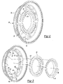
Figure 2 is a perspective view of an assembly that forms a portion of the gas turbine engine ofFigure 1 . -
Figure 3 is an exploded view of the assembly ofFigure 2 . -
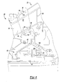
Figure 4 shows the assembly ofFigure 2 within the environment of a gas turbine engine. -
Figure 5 shows a portion of the assembly ofFigure 4 in a disassembled state. -
Figure 6 shows a portion of the assembly ofFigure 5 in a reassembled state. - Referring to
FIGS. 1-2 , agas turbine engine 10 includes afan 12, alow pressure compressor 14, ahigh pressure compressor 16, acombustor 18, alow pressure turbine 20, ahigh pressure turbine 22, alow pressure spool 24, ahigh pressure spool 26, and anozzle 28. Each compressor andturbine section low pressure spool 24 extends between, and connects thelow pressure compressor 14 to thelow pressure turbine 20 and thefan 12. Thehigh pressure spool 26 extends between, and is connected with, thehigh pressure compressor 16 and thehigh pressure turbine 22. Thelow pressure spool 24 and thehigh pressure spool 26 are concentric and rotatable about the longitudinally extendingaxis 30 of the engine. One of ordinary skill in the art will recognize that other arrangements of the components of thegas turbine engine 10 are within the teachings made herein. - Referring now to
Figures 2-4 , an embodiment of an assembly 38 (shown schematically inFig. 2 ) is disposed between thelow pressure turbine 20 and thehigh pressure turbine 22. Theassembly 38 supports bearings rotatably supporting thelow pressure spool 24 and thehigh pressure spool 26 as will be discussed hereinbelow. Theassembly 38 has acasing 39, aring structure 40 disposed within thecasing 39, and acover 45 for attaching theassembly 39 to abearing structure 50. Thecasing 39 is attached to the ring structure 40 (e.g., an inner assembly) by struts 32 (e.g., an outer assembly). The ring structure and thecover 45 form a torque box that resists bending and thrust moments. - Referring to
Figure 4 , eachstrut 32 fits within a hot air passage 55 through which highly energized air passes from thehigh pressure turbine 20 to thelow pressure turbine 22. Eachstrut 32 is enclosed by afairing 60, which directs air to thelow pressure turbine 22 at a particular angle as is known in the art. Thebearing structure 50 has a high pressure spool bearing 65, and a low pressure spool bearing 70 that are supported thereby and as will be discussed herein. - Referring back to
Figures 2-4 ,struts 32 are welded at theirouter diameters 75 to thecasing 39. Theinner diameter portions 80 of eachstrut 32 form the shape of a cone about avirtual perimeter 83 thereof. A pair ofbolt holes 85 is disposed in aninner diameter 80 of thestruts 32. Eachstrut 32 essentially forms an I-beam shape 90 and has a pair ofbeams 95 each having abolt hole 85 therein. Thebeams 95 are connected by aweb 100. Thestruts 32 are disposed at a particular angle relative to the air flow passing through thegas turbine engine 10 to provide stiffness in the radial and axial directions to counteract the massive torque created by combustion gases passing over turbine airfoils within thegas turbine engine 10. Aninner diameter 80 has an angle α relative toaxis 30 passing through thegas turbine engine 10 to conform with the shape of the hot air passage 55 (seeFigures 4 and6 ). Thebeams 95 are circular but other shapes are within the teachings described herein. The struts have good stiffness and torsional rigidity fore and aft. The angles of the struts could be between 30° and 60° relative to a direction of flow through theengine 10. - The
ring structure 40 has an outwardlyangled surface 105 that cooperates with theinner diameter 80 of thestruts 32 also at angle α relative toaxis 30 passing through thegas turbine engine 10. Thesurface 105 creates a conical surface about thering structure perimeter 107.Oversized holes 110 passing through theangled surface 105 receive bolts 115 (e.g., fasteners) there through that attach within thebolt holes 85 in thebeams 95 of thestruts 32. See alsoFigure 6 . - Referring now to
Figures 4-6 , thering structure 40 has a first radially inwardly extendingflange 120 extending from afirst end 125 thereof, and a second radially inwardly extendingflange 130 extending from asecond end 135 thereof. A first axially extendingflange 140 extends axially aft from the first radially inwardly extendingflange 120 to mate with theinner cover 45 as will be discussed herein. Similarly, the second radially inwardly extendingflange 130 also mates with thecover assembly 45 as will be discussed herein. - The
cover 45 has a second axially extendingflange 145 cooperating with the first axially extendingflange 140 for attachment thereto by bolts or other means. A third radially extendingflange 150 cooperates with the second radially extendingflange 120 on thering structure 40. A fourth radially extendingflange 155 that extends radially outwardly from the second axially extendingflange 145 attaches to the bearing structure 15 as will be discussed herein. The third radially extendingflange 150 and fourth radially extendingflange 155 are connected by anaxially extending connector 160. - The bearing
structure 50 has anupright bracket 170 that attaches to the fourth radially inwardly extendingflange 155 by bolts or otherwise. Anangled support 175 extends axially forward and has an attachingattachment 180 that supports aU-shaped land 185 having aland surface 190. Theland surface 190 supportsbearings 65 attaching to the highpressure spool bearing 65. Similarly, complementary bracket 195 (seeFigure 3-4 ) extends radially aft and supports aland 200 which supports bearings bearing 70 about which the low pressure spool rotates. - While machining is remarkably accurate, there are always some intolerances within an
engine 10. In order to minimize the effect of the intolerances, and the stresses that may accompany them, theassembly 38 takes the intolerances into account. For instance,oversized holes 110 allow sliding along the inner diameter end 80 of the struts and theangled surface 105 of the ring structure as thelow pressure spool 24 and thehigh pressure spool 26 are aligned alongaxis 30. The perimeter of thestruts 32 aligns with theperimeter 107 of theangled surface 105 Because thelands inner diameter 80 and the ring structure outerangled surface 105 causes thelands bearings - Although an embodiment of this invention has been disclosed, a worker of ordinary skill in this art would recognize that certain modifications would come within the scope of this invention. One of ordinary skill in the art will recognize that the teachings herein are applicable to other bearing assemblies, including other bearing assemblies in gas turbine engines.
- For that reason, the following claims should be studied to determine the true scope and content of this invention.
Claims (15)
- A bearing assembly for a gas turbine engine, said assembly comprising:a bearing (65; 70),an outer assembly disposed about an axis and having an angled perimeter (83), andan inner assembly supporting said bearing and having a surface (105) angled to slide against and attach to said angled perimeter (83) as said bearing is aligned with said axis.
- The bearing assembly of claim 1 wherein said outer assembly includes a plurality of struts (32) attached to an outer casing (39).
- The bearing assembly of claim 2 wherein said struts (32) comprise an I-beam shape.
- The bearing assembly of claim 2 or 3 wherein said surface (105) slides along an inner diameter of said struts (32) as said bearing is aligned with said axis.
- The bearing assembly of claim 4 wherein fasteners (115), e.g. bolts, pass through openings (110) in said surface (105) and attach to said struts (32).
- The bearing surface of claim 5 wherein said openings (110) are greater than a diameter of said fastener (115) to allow relative movement between said struts (32) and said surface (105) while aligning said bearing with said axis.
- The bearing assembly of any preceding claim wherein said inner assembly is a cone (40).
- The bearing assembly of any preceding claim further comprising:a support (45) disposed between said inner assembly and said bearing wherein said support (45) and said inner assembly form a torque box.
- The bearing assembly of any preceding claim wherein said bearing supports a low pressure spool (24) and/or a high pressure spool (26).
- A assembly (38) for supporting a bearing comprising:an outer casing (39),an inner casing (40) having an outer surface (105),a plurality of struts (32) connecting said inner casing (40) and said outer casing (39), each strut (32) having a surface (80) disposed at a complementary angle to said outer surface (105) wherein said surface (80) and said outer surface (105) move relative to each other in plane as said bearing is aligned along an axis, anda fastener (115) for attaching said surface (80) to said outer surface (105) after said bearing is aligned with said axis.
- The assembly of claim 10 wherein each strut (32) has a pair of end portions (95) each end portion (95) having an opening (85) for receiving said fastener (115) therein.
- The assembly of claim 10 or 11 wherein each end portion (95) is rod-shaped.
- The assembly of claim 10, 11 or 12 wherein said end portions (95) are connected by a web (100).
- The assembly of any of claims 10 to 13 wherein said fastener, e.g. a bolt (115), passes through an oversized opening (110) in said outer surface (105) to allow relative movement between said outer surface (105) and said surface (80) in plane.
- A method of assembling a rotating engine, said method comprising
providing a bearing (65, 70),
providing an outer assembly disposed about an axis and having an angled perimeter (83) greater than zero degrees,
providing an inner assembly (40) for supporting said bearing and having a surface (105) angled at a same angle as said perimeter (83),
sliding said angled perimeter (83) along said surface (105) in plane while aligning said bearing along said axis; and optionally further comprising:affixing said angled perimeter (83) to said surface (105) after aligning said bearing (65; 70) along said axis; and/orproviding oversized fastening holes (110) in one of said inner assembly or said outer assembly to permit attachment of said inner assembly to said outer assembly after aligning said bearing (65; 70) along said axis.
Applications Claiming Priority (1)
| Application Number | Priority Date | Filing Date | Title |
|---|---|---|---|
| US13/290,598 US8979483B2 (en) | 2011-11-07 | 2011-11-07 | Mid-turbine bearing support |
Publications (3)
| Publication Number | Publication Date |
|---|---|
| EP2589759A2 true EP2589759A2 (en) | 2013-05-08 |
| EP2589759A3 EP2589759A3 (en) | 2016-10-19 |
| EP2589759B1 EP2589759B1 (en) | 2019-06-12 |
Family
ID=47146196
Family Applications (1)
| Application Number | Title | Priority Date | Filing Date |
|---|---|---|---|
| EP12190437.9A Active EP2589759B1 (en) | 2011-11-07 | 2012-10-29 | Mid-Turbine Bearing Support |
Country Status (2)
| Country | Link |
|---|---|
| US (1) | US8979483B2 (en) |
| EP (1) | EP2589759B1 (en) |
Cited By (1)
| Publication number | Priority date | Publication date | Assignee | Title |
|---|---|---|---|---|
| EP2636855A1 (en) * | 2012-03-05 | 2013-09-11 | General Electric Company | Gas turbine frame stiffening rails |
Families Citing this family (8)
| Publication number | Priority date | Publication date | Assignee | Title |
|---|---|---|---|---|
| US9328626B2 (en) * | 2012-08-21 | 2016-05-03 | United Technologies Corporation | Annular turbomachine seal and heat shield |
| US9856741B2 (en) * | 2014-10-13 | 2018-01-02 | Pw Power Systems, Inc. | Power turbine cooling air metering ring |
| US9945240B2 (en) * | 2014-10-13 | 2018-04-17 | Pw Power Systems, Inc. | Power turbine heat shield architecture |
| US20160201512A1 (en) * | 2015-01-09 | 2016-07-14 | United Technologies Corporation | Gas turbine engine mid-turbine frame tie rod arrangement |
| US9885254B2 (en) * | 2015-04-24 | 2018-02-06 | United Technologies Corporation | Mid turbine frame including a sealed torque box |
| US11306726B2 (en) | 2019-03-11 | 2022-04-19 | Emerson Climate Technologies, Inc. | Foil bearing assembly and compressor including same |
| CN116951008A (en) * | 2023-07-17 | 2023-10-27 | 中国航发沈阳发动机研究所 | A straight-arm low-pressure turbine shaft flange with special-shaped holes |
| FR3167131A1 (en) * | 2024-10-09 | 2026-04-10 | Safran Nacelles | PROPULSION ASSEMBLY FOR AN AIRCRAFT |
Family Cites Families (12)
| Publication number | Priority date | Publication date | Assignee | Title |
|---|---|---|---|---|
| US5224341A (en) * | 1992-01-06 | 1993-07-06 | United Technologies Corporation | Separable fan strut for a gas turbofan powerplant |
| US5272869A (en) * | 1992-12-10 | 1993-12-28 | General Electric Company | Turbine frame |
| US6439841B1 (en) * | 2000-04-29 | 2002-08-27 | General Electric Company | Turbine frame assembly |
| US6708482B2 (en) | 2001-11-29 | 2004-03-23 | General Electric Company | Aircraft engine with inter-turbine engine frame |
| US7677047B2 (en) * | 2006-03-29 | 2010-03-16 | United Technologies Corporation | Inverted stiffened shell panel torque transmission for loaded struts and mid-turbine frames |
| US7775049B2 (en) | 2006-04-04 | 2010-08-17 | United Technologies Corporation | Integrated strut design for mid-turbine frames with U-base |
| US7797946B2 (en) * | 2006-12-06 | 2010-09-21 | United Technologies Corporation | Double U design for mid-turbine frame struts |
| US8312726B2 (en) * | 2007-12-21 | 2012-11-20 | United Technologies Corp. | Gas turbine engine systems involving I-beam struts |
| FR2933130B1 (en) * | 2008-06-25 | 2012-02-24 | Snecma | STRUCTURAL CASING FOR TURBOMACHINE |
| US8347500B2 (en) * | 2008-11-28 | 2013-01-08 | Pratt & Whitney Canada Corp. | Method of assembly and disassembly of a gas turbine mid turbine frame |
| US8568083B2 (en) | 2009-09-04 | 2013-10-29 | United Technologies Corporation | Spool support structure for a multi-spool gas turbine engine |
| US8316523B2 (en) * | 2009-10-01 | 2012-11-27 | Pratt & Whitney Canada Corp. | Method for centering engine structures |
-
2011
- 2011-11-07 US US13/290,598 patent/US8979483B2/en active Active
-
2012
- 2012-10-29 EP EP12190437.9A patent/EP2589759B1/en active Active
Non-Patent Citations (1)
| Title |
|---|
| None |
Cited By (2)
| Publication number | Priority date | Publication date | Assignee | Title |
|---|---|---|---|---|
| EP2636855A1 (en) * | 2012-03-05 | 2013-09-11 | General Electric Company | Gas turbine frame stiffening rails |
| US9316108B2 (en) | 2012-03-05 | 2016-04-19 | General Electric Company | Gas turbine frame stiffening rails |
Also Published As
| Publication number | Publication date |
|---|---|
| EP2589759B1 (en) | 2019-06-12 |
| EP2589759A3 (en) | 2016-10-19 |
| US20130115057A1 (en) | 2013-05-09 |
| US8979483B2 (en) | 2015-03-17 |
Similar Documents
| Publication | Publication Date | Title |
|---|---|---|
| EP2589759B1 (en) | Mid-Turbine Bearing Support | |
| CA2680629C (en) | Integrated guide vane assembly | |
| CA2762810C (en) | Variable geometry vane system for gas turbine engines | |
| CA2862397C (en) | Gas turbine engine inlet assembly and method of making same | |
| US20050109013A1 (en) | Turbofan case and method of making | |
| US9133723B2 (en) | Shield system for gas turbine engine | |
| US20150337687A1 (en) | Split cast vane fairing | |
| EP3225792A1 (en) | Attachment system between a strut and an engine casing | |
| EP2971681B1 (en) | Turbofan engine assembly methods and turbofan engine | |
| EP2472070A2 (en) | Methods of manufacturing a gas turbine engine case and corresponding case | |
| US10329957B2 (en) | Turbine exhaust case multi-piece framed | |
| US11131209B2 (en) | Gas turbine | |
| US10955045B2 (en) | Planet carrier and method of assembling of a planet carrier | |
| EP3546367B1 (en) | A geared turbofan engine mount arrangement | |
| US20200263555A1 (en) | Turbomachine with Alternatingly Spaced Rotor Blades | |
| US11795839B2 (en) | Structural assembly for a gas turbine engine | |
| EP3623581B1 (en) | Integral vane stage | |
| US20200224545A1 (en) | Shroud and shroud assembly process for variable vane assemblies | |
| US10711648B2 (en) | Nosecone support | |
| US20200063604A1 (en) | Gas turbine engine |
Legal Events
| Date | Code | Title | Description |
|---|---|---|---|
| PUAI | Public reference made under article 153(3) epc to a published international application that has entered the european phase |
Free format text: ORIGINAL CODE: 0009012 |
|
| AK | Designated contracting states |
Kind code of ref document: A2 Designated state(s): AL AT BE BG CH CY CZ DE DK EE ES FI FR GB GR HR HU IE IS IT LI LT LU LV MC MK MT NL NO PL PT RO RS SE SI SK SM TR |
|
| AX | Request for extension of the european patent |
Extension state: BA ME |
|
| PUAL | Search report despatched |
Free format text: ORIGINAL CODE: 0009013 |
|
| AK | Designated contracting states |
Kind code of ref document: A3 Designated state(s): AL AT BE BG CH CY CZ DE DK EE ES FI FR GB GR HR HU IE IS IT LI LT LU LV MC MK MT NL NO PL PT RO RS SE SI SK SM TR |
|
| AX | Request for extension of the european patent |
Extension state: BA ME |
|
| RIC1 | Information provided on ipc code assigned before grant |
Ipc: F01D 25/16 20060101AFI20160915BHEP |
|
| RAP1 | Party data changed (applicant data changed or rights of an application transferred) |
Owner name: UNITED TECHNOLOGIES CORPORATION |
|
| STAA | Information on the status of an ep patent application or granted ep patent |
Free format text: STATUS: REQUEST FOR EXAMINATION WAS MADE |
|
| 17P | Request for examination filed |
Effective date: 20170419 |
|
| RBV | Designated contracting states (corrected) |
Designated state(s): AL AT BE BG CH CY CZ DE DK EE ES FI FR GB GR HR HU IE IS IT LI LT LU LV MC MK MT NL NO PL PT RO RS SE SI SK SM TR |
|
| GRAP | Despatch of communication of intention to grant a patent |
Free format text: ORIGINAL CODE: EPIDOSNIGR1 |
|
| STAA | Information on the status of an ep patent application or granted ep patent |
Free format text: STATUS: GRANT OF PATENT IS INTENDED |
|
| INTG | Intention to grant announced |
Effective date: 20181022 |
|
| GRAJ | Information related to disapproval of communication of intention to grant by the applicant or resumption of examination proceedings by the epo deleted |
Free format text: ORIGINAL CODE: EPIDOSDIGR1 |
|
| STAA | Information on the status of an ep patent application or granted ep patent |
Free format text: STATUS: REQUEST FOR EXAMINATION WAS MADE |
|
| GRAP | Despatch of communication of intention to grant a patent |
Free format text: ORIGINAL CODE: EPIDOSNIGR1 |
|
| STAA | Information on the status of an ep patent application or granted ep patent |
Free format text: STATUS: GRANT OF PATENT IS INTENDED |
|
| INTG | Intention to grant announced |
Effective date: 20190318 |
|
| GRAS | Grant fee paid |
Free format text: ORIGINAL CODE: EPIDOSNIGR3 |
|
| GRAA | (expected) grant |
Free format text: ORIGINAL CODE: 0009210 |
|
| STAA | Information on the status of an ep patent application or granted ep patent |
Free format text: STATUS: THE PATENT HAS BEEN GRANTED |
|
| AK | Designated contracting states |
Kind code of ref document: B1 Designated state(s): AL AT BE BG CH CY CZ DE DK EE ES FI FR GB GR HR HU IE IS IT LI LT LU LV MC MK MT NL NO PL PT RO RS SE SI SK SM TR |
|
| REG | Reference to a national code |
Ref country code: GB Ref legal event code: FG4D |
|
| REG | Reference to a national code |
Ref country code: CH Ref legal event code: EP |
|
| REG | Reference to a national code |
Ref country code: AT Ref legal event code: REF Ref document number: 1142809 Country of ref document: AT Kind code of ref document: T Effective date: 20190615 |
|
| REG | Reference to a national code |
Ref country code: DE Ref legal event code: R096 Ref document number: 602012060869 Country of ref document: DE |
|
| REG | Reference to a national code |
Ref country code: IE Ref legal event code: FG4D |
|
| REG | Reference to a national code |
Ref country code: NL Ref legal event code: MP Effective date: 20190612 |
|
| REG | Reference to a national code |
Ref country code: LT Ref legal event code: MG4D |
|
| PG25 | Lapsed in a contracting state [announced via postgrant information from national office to epo] |
Ref country code: ES Free format text: LAPSE BECAUSE OF FAILURE TO SUBMIT A TRANSLATION OF THE DESCRIPTION OR TO PAY THE FEE WITHIN THE PRESCRIBED TIME-LIMIT Effective date: 20190612 Ref country code: AL Free format text: LAPSE BECAUSE OF FAILURE TO SUBMIT A TRANSLATION OF THE DESCRIPTION OR TO PAY THE FEE WITHIN THE PRESCRIBED TIME-LIMIT Effective date: 20190612 Ref country code: SE Free format text: LAPSE BECAUSE OF FAILURE TO SUBMIT A TRANSLATION OF THE DESCRIPTION OR TO PAY THE FEE WITHIN THE PRESCRIBED TIME-LIMIT Effective date: 20190612 Ref country code: FI Free format text: LAPSE BECAUSE OF FAILURE TO SUBMIT A TRANSLATION OF THE DESCRIPTION OR TO PAY THE FEE WITHIN THE PRESCRIBED TIME-LIMIT Effective date: 20190612 Ref country code: NO Free format text: LAPSE BECAUSE OF FAILURE TO SUBMIT A TRANSLATION OF THE DESCRIPTION OR TO PAY THE FEE WITHIN THE PRESCRIBED TIME-LIMIT Effective date: 20190912 Ref country code: LT Free format text: LAPSE BECAUSE OF FAILURE TO SUBMIT A TRANSLATION OF THE DESCRIPTION OR TO PAY THE FEE WITHIN THE PRESCRIBED TIME-LIMIT Effective date: 20190612 Ref country code: HR Free format text: LAPSE BECAUSE OF FAILURE TO SUBMIT A TRANSLATION OF THE DESCRIPTION OR TO PAY THE FEE WITHIN THE PRESCRIBED TIME-LIMIT Effective date: 20190612 |
|
| PG25 | Lapsed in a contracting state [announced via postgrant information from national office to epo] |
Ref country code: GR Free format text: LAPSE BECAUSE OF FAILURE TO SUBMIT A TRANSLATION OF THE DESCRIPTION OR TO PAY THE FEE WITHIN THE PRESCRIBED TIME-LIMIT Effective date: 20190913 Ref country code: LV Free format text: LAPSE BECAUSE OF FAILURE TO SUBMIT A TRANSLATION OF THE DESCRIPTION OR TO PAY THE FEE WITHIN THE PRESCRIBED TIME-LIMIT Effective date: 20190612 Ref country code: BG Free format text: LAPSE BECAUSE OF FAILURE TO SUBMIT A TRANSLATION OF THE DESCRIPTION OR TO PAY THE FEE WITHIN THE PRESCRIBED TIME-LIMIT Effective date: 20190912 Ref country code: RS Free format text: LAPSE BECAUSE OF FAILURE TO SUBMIT A TRANSLATION OF THE DESCRIPTION OR TO PAY THE FEE WITHIN THE PRESCRIBED TIME-LIMIT Effective date: 20190612 |
|
| REG | Reference to a national code |
Ref country code: AT Ref legal event code: MK05 Ref document number: 1142809 Country of ref document: AT Kind code of ref document: T Effective date: 20190612 |
|
| PG25 | Lapsed in a contracting state [announced via postgrant information from national office to epo] |
Ref country code: NL Free format text: LAPSE BECAUSE OF FAILURE TO SUBMIT A TRANSLATION OF THE DESCRIPTION OR TO PAY THE FEE WITHIN THE PRESCRIBED TIME-LIMIT Effective date: 20190612 Ref country code: AT Free format text: LAPSE BECAUSE OF FAILURE TO SUBMIT A TRANSLATION OF THE DESCRIPTION OR TO PAY THE FEE WITHIN THE PRESCRIBED TIME-LIMIT Effective date: 20190612 Ref country code: EE Free format text: LAPSE BECAUSE OF FAILURE TO SUBMIT A TRANSLATION OF THE DESCRIPTION OR TO PAY THE FEE WITHIN THE PRESCRIBED TIME-LIMIT Effective date: 20190612 Ref country code: RO Free format text: LAPSE BECAUSE OF FAILURE TO SUBMIT A TRANSLATION OF THE DESCRIPTION OR TO PAY THE FEE WITHIN THE PRESCRIBED TIME-LIMIT Effective date: 20190612 Ref country code: CZ Free format text: LAPSE BECAUSE OF FAILURE TO SUBMIT A TRANSLATION OF THE DESCRIPTION OR TO PAY THE FEE WITHIN THE PRESCRIBED TIME-LIMIT Effective date: 20190612 Ref country code: PT Free format text: LAPSE BECAUSE OF FAILURE TO SUBMIT A TRANSLATION OF THE DESCRIPTION OR TO PAY THE FEE WITHIN THE PRESCRIBED TIME-LIMIT Effective date: 20191014 Ref country code: SK Free format text: LAPSE BECAUSE OF FAILURE TO SUBMIT A TRANSLATION OF THE DESCRIPTION OR TO PAY THE FEE WITHIN THE PRESCRIBED TIME-LIMIT Effective date: 20190612 |
|
| PG25 | Lapsed in a contracting state [announced via postgrant information from national office to epo] |
Ref country code: IT Free format text: LAPSE BECAUSE OF FAILURE TO SUBMIT A TRANSLATION OF THE DESCRIPTION OR TO PAY THE FEE WITHIN THE PRESCRIBED TIME-LIMIT Effective date: 20190612 Ref country code: SM Free format text: LAPSE BECAUSE OF FAILURE TO SUBMIT A TRANSLATION OF THE DESCRIPTION OR TO PAY THE FEE WITHIN THE PRESCRIBED TIME-LIMIT Effective date: 20190612 Ref country code: IS Free format text: LAPSE BECAUSE OF FAILURE TO SUBMIT A TRANSLATION OF THE DESCRIPTION OR TO PAY THE FEE WITHIN THE PRESCRIBED TIME-LIMIT Effective date: 20191012 |
|
| REG | Reference to a national code |
Ref country code: DE Ref legal event code: R097 Ref document number: 602012060869 Country of ref document: DE |
|
| PG25 | Lapsed in a contracting state [announced via postgrant information from national office to epo] |
Ref country code: TR Free format text: LAPSE BECAUSE OF FAILURE TO SUBMIT A TRANSLATION OF THE DESCRIPTION OR TO PAY THE FEE WITHIN THE PRESCRIBED TIME-LIMIT Effective date: 20190612 |
|
| PLBE | No opposition filed within time limit |
Free format text: ORIGINAL CODE: 0009261 |
|
| STAA | Information on the status of an ep patent application or granted ep patent |
Free format text: STATUS: NO OPPOSITION FILED WITHIN TIME LIMIT |
|
| PG25 | Lapsed in a contracting state [announced via postgrant information from national office to epo] |
Ref country code: DK Free format text: LAPSE BECAUSE OF FAILURE TO SUBMIT A TRANSLATION OF THE DESCRIPTION OR TO PAY THE FEE WITHIN THE PRESCRIBED TIME-LIMIT Effective date: 20190612 Ref country code: PL Free format text: LAPSE BECAUSE OF FAILURE TO SUBMIT A TRANSLATION OF THE DESCRIPTION OR TO PAY THE FEE WITHIN THE PRESCRIBED TIME-LIMIT Effective date: 20190612 |
|
| 26N | No opposition filed |
Effective date: 20200313 |
|
| PG25 | Lapsed in a contracting state [announced via postgrant information from national office to epo] |
Ref country code: IS Free format text: LAPSE BECAUSE OF FAILURE TO SUBMIT A TRANSLATION OF THE DESCRIPTION OR TO PAY THE FEE WITHIN THE PRESCRIBED TIME-LIMIT Effective date: 20200224 Ref country code: MC Free format text: LAPSE BECAUSE OF FAILURE TO SUBMIT A TRANSLATION OF THE DESCRIPTION OR TO PAY THE FEE WITHIN THE PRESCRIBED TIME-LIMIT Effective date: 20190612 Ref country code: SI Free format text: LAPSE BECAUSE OF FAILURE TO SUBMIT A TRANSLATION OF THE DESCRIPTION OR TO PAY THE FEE WITHIN THE PRESCRIBED TIME-LIMIT Effective date: 20190612 |
|
| REG | Reference to a national code |
Ref country code: CH Ref legal event code: PL |
|
| PG2D | Information on lapse in contracting state deleted |
Ref country code: IS |
|
| PG25 | Lapsed in a contracting state [announced via postgrant information from national office to epo] |
Ref country code: CH Free format text: LAPSE BECAUSE OF NON-PAYMENT OF DUE FEES Effective date: 20191031 Ref country code: LU Free format text: LAPSE BECAUSE OF NON-PAYMENT OF DUE FEES Effective date: 20191029 Ref country code: LI Free format text: LAPSE BECAUSE OF NON-PAYMENT OF DUE FEES Effective date: 20191031 |
|
| REG | Reference to a national code |
Ref country code: BE Ref legal event code: MM Effective date: 20191031 |
|
| PG25 | Lapsed in a contracting state [announced via postgrant information from national office to epo] |
Ref country code: BE Free format text: LAPSE BECAUSE OF NON-PAYMENT OF DUE FEES Effective date: 20191031 |
|
| PG25 | Lapsed in a contracting state [announced via postgrant information from national office to epo] |
Ref country code: IE Free format text: LAPSE BECAUSE OF NON-PAYMENT OF DUE FEES Effective date: 20191029 |
|
| PG25 | Lapsed in a contracting state [announced via postgrant information from national office to epo] |
Ref country code: CY Free format text: LAPSE BECAUSE OF FAILURE TO SUBMIT A TRANSLATION OF THE DESCRIPTION OR TO PAY THE FEE WITHIN THE PRESCRIBED TIME-LIMIT Effective date: 20190612 |
|
| PG25 | Lapsed in a contracting state [announced via postgrant information from national office to epo] |
Ref country code: MT Free format text: LAPSE BECAUSE OF FAILURE TO SUBMIT A TRANSLATION OF THE DESCRIPTION OR TO PAY THE FEE WITHIN THE PRESCRIBED TIME-LIMIT Effective date: 20190612 Ref country code: HU Free format text: LAPSE BECAUSE OF FAILURE TO SUBMIT A TRANSLATION OF THE DESCRIPTION OR TO PAY THE FEE WITHIN THE PRESCRIBED TIME-LIMIT; INVALID AB INITIO Effective date: 20121029 |
|
| PG25 | Lapsed in a contracting state [announced via postgrant information from national office to epo] |
Ref country code: MK Free format text: LAPSE BECAUSE OF FAILURE TO SUBMIT A TRANSLATION OF THE DESCRIPTION OR TO PAY THE FEE WITHIN THE PRESCRIBED TIME-LIMIT Effective date: 20190612 |
|
| REG | Reference to a national code |
Ref country code: DE Ref legal event code: R081 Ref document number: 602012060869 Country of ref document: DE Owner name: RAYTHEON TECHNOLOGIES CORPORATION (N.D.GES.D.S, US Free format text: FORMER OWNER: UNITED TECHNOLOGIES CORPORATION, FARMINGTON, CONN., US |
|
| P01 | Opt-out of the competence of the unified patent court (upc) registered |
Effective date: 20230520 |
|
| PGFP | Annual fee paid to national office [announced via postgrant information from national office to epo] |
Ref country code: GB Payment date: 20240919 Year of fee payment: 13 |
|
| PGFP | Annual fee paid to national office [announced via postgrant information from national office to epo] |
Ref country code: FR Payment date: 20240919 Year of fee payment: 13 |
|
| PGFP | Annual fee paid to national office [announced via postgrant information from national office to epo] |
Ref country code: DE Payment date: 20240919 Year of fee payment: 13 |