EP2589572A1 - Protein-enclosed carbon nanotube film, and sensor and power-generating device each equipped with the carbon nanotube film as electrode - Google Patents
Protein-enclosed carbon nanotube film, and sensor and power-generating device each equipped with the carbon nanotube film as electrode Download PDFInfo
- Publication number
- EP2589572A1 EP2589572A1 EP11800755.8A EP11800755A EP2589572A1 EP 2589572 A1 EP2589572 A1 EP 2589572A1 EP 11800755 A EP11800755 A EP 11800755A EP 2589572 A1 EP2589572 A1 EP 2589572A1
- Authority
- EP
- European Patent Office
- Prior art keywords
- carbon nanotube
- nanotube film
- enzyme
- electrode
- aggregate
- Prior art date
- Legal status (The legal status is an assumption and is not a legal conclusion. Google has not performed a legal analysis and makes no representation as to the accuracy of the status listed.)
- Withdrawn
Links
- 239000002238 carbon nanotube film Substances 0.000 title claims abstract description 231
- 239000002041 carbon nanotube Substances 0.000 claims abstract description 147
- 102000004190 Enzymes Human genes 0.000 claims abstract description 146
- 108090000790 Enzymes Proteins 0.000 claims abstract description 146
- OKTJSMMVPCPJKN-UHFFFAOYSA-N Carbon Chemical compound [C] OKTJSMMVPCPJKN-UHFFFAOYSA-N 0.000 claims abstract description 144
- 229910021393 carbon nanotube Inorganic materials 0.000 claims abstract description 137
- 102000004169 proteins and genes Human genes 0.000 claims abstract description 31
- 108090000623 proteins and genes Proteins 0.000 claims abstract description 31
- 239000004094 surface-active agent Substances 0.000 claims abstract description 16
- 230000004931 aggregating effect Effects 0.000 claims abstract description 3
- 239000000243 solution Substances 0.000 claims description 46
- 239000000758 substrate Substances 0.000 claims description 40
- 238000004519 manufacturing process Methods 0.000 claims description 26
- 239000007853 buffer solution Substances 0.000 claims description 23
- 239000000446 fuel Substances 0.000 claims description 22
- 101710088194 Dehydrogenase Proteins 0.000 claims description 7
- 108090000854 Oxidoreductases Proteins 0.000 claims description 7
- 102000004316 Oxidoreductases Human genes 0.000 claims description 7
- 239000011148 porous material Substances 0.000 claims description 4
- 238000009826 distribution Methods 0.000 claims description 3
- 238000011161 development Methods 0.000 abstract description 4
- 229940088598 enzyme Drugs 0.000 description 134
- 238000000034 method Methods 0.000 description 73
- RFSUNEUAIZKAJO-ARQDHWQXSA-N Fructose Chemical compound OC[C@H]1O[C@](O)(CO)[C@@H](O)[C@@H]1O RFSUNEUAIZKAJO-ARQDHWQXSA-N 0.000 description 33
- 230000000052 comparative effect Effects 0.000 description 32
- 238000011156 evaluation Methods 0.000 description 31
- 229930091371 Fructose Natural products 0.000 description 30
- 229960002737 fructose Drugs 0.000 description 30
- 239000005715 Fructose Substances 0.000 description 28
- 238000001035 drying Methods 0.000 description 23
- 238000005259 measurement Methods 0.000 description 22
- 230000008569 process Effects 0.000 description 22
- 238000003756 stirring Methods 0.000 description 20
- 230000000694 effects Effects 0.000 description 17
- 108010015428 Bilirubin oxidase Proteins 0.000 description 16
- 239000000872 buffer Substances 0.000 description 11
- 230000003068 static effect Effects 0.000 description 11
- LFQSCWFLJHTTHZ-UHFFFAOYSA-N Ethanol Chemical compound CCO LFQSCWFLJHTTHZ-UHFFFAOYSA-N 0.000 description 9
- 239000012298 atmosphere Substances 0.000 description 9
- 238000007781 pre-processing Methods 0.000 description 9
- 108010029541 Laccase Proteins 0.000 description 7
- 229910052799 carbon Inorganic materials 0.000 description 7
- 239000000463 material Substances 0.000 description 7
- 230000003287 optical effect Effects 0.000 description 7
- 230000003647 oxidation Effects 0.000 description 7
- 238000007254 oxidation reaction Methods 0.000 description 7
- 229910021607 Silver chloride Inorganic materials 0.000 description 6
- PCHJSUWPFVWCPO-UHFFFAOYSA-N gold Chemical compound [Au] PCHJSUWPFVWCPO-UHFFFAOYSA-N 0.000 description 6
- BASFCYQUMIYNBI-UHFFFAOYSA-N platinum Chemical compound [Pt] BASFCYQUMIYNBI-UHFFFAOYSA-N 0.000 description 6
- HKZLPVFGJNLROG-UHFFFAOYSA-M silver monochloride Chemical compound [Cl-].[Ag+] HKZLPVFGJNLROG-UHFFFAOYSA-M 0.000 description 6
- IJGRMHOSHXDMSA-UHFFFAOYSA-N Atomic nitrogen Chemical compound N#N IJGRMHOSHXDMSA-UHFFFAOYSA-N 0.000 description 5
- 239000002551 biofuel Substances 0.000 description 5
- 239000003054 catalyst Substances 0.000 description 5
- 238000006243 chemical reaction Methods 0.000 description 5
- 238000002848 electrochemical method Methods 0.000 description 5
- 230000033116 oxidation-reduction process Effects 0.000 description 5
- 229920006395 saturated elastomer Polymers 0.000 description 5
- 239000007787 solid Substances 0.000 description 5
- MWNLTKCQHFZFHN-UHFFFAOYSA-N CBQCA reagent Chemical compound C1=CC(C(=O)O)=CC=C1C(=O)C1=CC2=CC=CC=C2N=C1C=O MWNLTKCQHFZFHN-UHFFFAOYSA-N 0.000 description 4
- RFSUNEUAIZKAJO-VRPWFDPXSA-N D-Fructose Natural products OC[C@H]1OC(O)(CO)[C@@H](O)[C@@H]1O RFSUNEUAIZKAJO-VRPWFDPXSA-N 0.000 description 4
- WQZGKKKJIJFFOK-GASJEMHNSA-N Glucose Chemical group OC[C@H]1OC(O)[C@H](O)[C@@H](O)[C@@H]1O WQZGKKKJIJFFOK-GASJEMHNSA-N 0.000 description 4
- XUIMIQQOPSSXEZ-UHFFFAOYSA-N Silicon Chemical compound [Si] XUIMIQQOPSSXEZ-UHFFFAOYSA-N 0.000 description 4
- 239000010931 gold Substances 0.000 description 4
- 229910052737 gold Inorganic materials 0.000 description 4
- JVTAAEKCZFNVCJ-UHFFFAOYSA-N lactic acid Chemical compound CC(O)C(O)=O JVTAAEKCZFNVCJ-UHFFFAOYSA-N 0.000 description 4
- 239000001301 oxygen Substances 0.000 description 4
- 229910052760 oxygen Inorganic materials 0.000 description 4
- 230000009467 reduction Effects 0.000 description 4
- 238000006722 reduction reaction Methods 0.000 description 4
- 229910052710 silicon Inorganic materials 0.000 description 4
- 239000010703 silicon Substances 0.000 description 4
- 239000000126 substance Substances 0.000 description 4
- XLYOFNOQVPJJNP-UHFFFAOYSA-N water Substances O XLYOFNOQVPJJNP-UHFFFAOYSA-N 0.000 description 4
- OKKJLVBELUTLKV-UHFFFAOYSA-N Methanol Chemical compound OC OKKJLVBELUTLKV-UHFFFAOYSA-N 0.000 description 3
- -1 Polyethylene Terephthalate Polymers 0.000 description 3
- QVGXLLKOCUKJST-UHFFFAOYSA-N atomic oxygen Chemical compound [O] QVGXLLKOCUKJST-UHFFFAOYSA-N 0.000 description 3
- 239000010419 fine particle Substances 0.000 description 3
- 229910052757 nitrogen Inorganic materials 0.000 description 3
- 239000011368 organic material Substances 0.000 description 3
- 229910052697 platinum Inorganic materials 0.000 description 3
- 238000010248 power generation Methods 0.000 description 3
- 238000004804 winding Methods 0.000 description 3
- 102000007698 Alcohol dehydrogenase Human genes 0.000 description 2
- 108010021809 Alcohol dehydrogenase Proteins 0.000 description 2
- 108010005939 Ciliary Neurotrophic Factor Proteins 0.000 description 2
- 102100031614 Ciliary neurotrophic factor Human genes 0.000 description 2
- 102000043368 Multicopper oxidase Human genes 0.000 description 2
- CZMRCDWAGMRECN-UGDNZRGBSA-N Sucrose Chemical compound O[C@H]1[C@H](O)[C@@H](CO)O[C@@]1(CO)O[C@@H]1[C@H](O)[C@@H](O)[C@H](O)[C@@H](CO)O1 CZMRCDWAGMRECN-UGDNZRGBSA-N 0.000 description 2
- 229930006000 Sucrose Natural products 0.000 description 2
- 239000013504 Triton X-100 Substances 0.000 description 2
- 229920004890 Triton X-100 Polymers 0.000 description 2
- 239000000512 collagen gel Substances 0.000 description 2
- 230000008602 contraction Effects 0.000 description 2
- 239000013256 coordination polymer Substances 0.000 description 2
- 238000010586 diagram Methods 0.000 description 2
- 239000004205 dimethyl polysiloxane Substances 0.000 description 2
- 239000007772 electrode material Substances 0.000 description 2
- 230000007613 environmental effect Effects 0.000 description 2
- 238000002474 experimental method Methods 0.000 description 2
- 239000008103 glucose Substances 0.000 description 2
- 230000036541 health Effects 0.000 description 2
- 230000002209 hydrophobic effect Effects 0.000 description 2
- 235000014655 lactic acid Nutrition 0.000 description 2
- 239000004310 lactic acid Substances 0.000 description 2
- 239000011259 mixed solution Substances 0.000 description 2
- 238000012986 modification Methods 0.000 description 2
- 230000004048 modification Effects 0.000 description 2
- 238000012544 monitoring process Methods 0.000 description 2
- 108700020788 multicopper oxidase Proteins 0.000 description 2
- 239000002245 particle Substances 0.000 description 2
- 239000002953 phosphate buffered saline Substances 0.000 description 2
- 229920000435 poly(dimethylsiloxane) Polymers 0.000 description 2
- 229920000139 polyethylene terephthalate Polymers 0.000 description 2
- 239000005020 polyethylene terephthalate Substances 0.000 description 2
- 238000002360 preparation method Methods 0.000 description 2
- 238000006479 redox reaction Methods 0.000 description 2
- 230000002441 reversible effect Effects 0.000 description 2
- 239000005720 sucrose Substances 0.000 description 2
- 235000000346 sugar Nutrition 0.000 description 2
- 230000002123 temporal effect Effects 0.000 description 2
- 238000012360 testing method Methods 0.000 description 2
- LJCNDNBULVLKSG-UHFFFAOYSA-N 2-aminoacetic acid;butane Chemical compound CCCC.CCCC.NCC(O)=O LJCNDNBULVLKSG-UHFFFAOYSA-N 0.000 description 1
- 239000002028 Biomass Substances 0.000 description 1
- 108010050375 Glucose 1-Dehydrogenase Proteins 0.000 description 1
- 108010015776 Glucose oxidase Proteins 0.000 description 1
- 239000004366 Glucose oxidase Substances 0.000 description 1
- UFHFLCQGNIYNRP-UHFFFAOYSA-N Hydrogen Chemical compound [H][H] UFHFLCQGNIYNRP-UHFFFAOYSA-N 0.000 description 1
- 102000003855 L-lactate dehydrogenase Human genes 0.000 description 1
- 108700023483 L-lactate dehydrogenases Proteins 0.000 description 1
- 108010073450 Lactate 2-monooxygenase Proteins 0.000 description 1
- 229920001213 Polysorbate 20 Polymers 0.000 description 1
- 238000001237 Raman spectrum Methods 0.000 description 1
- 238000010521 absorption reaction Methods 0.000 description 1
- 238000004458 analytical method Methods 0.000 description 1
- 239000011230 binding agent Substances 0.000 description 1
- 230000005540 biological transmission Effects 0.000 description 1
- 229910021538 borax Inorganic materials 0.000 description 1
- 238000011088 calibration curve Methods 0.000 description 1
- 239000002134 carbon nanofiber Substances 0.000 description 1
- 230000015556 catabolic process Effects 0.000 description 1
- 238000005229 chemical vapour deposition Methods 0.000 description 1
- 239000004020 conductor Substances 0.000 description 1
- 239000000470 constituent Substances 0.000 description 1
- 238000010276 construction Methods 0.000 description 1
- 238000002425 crystallisation Methods 0.000 description 1
- 230000008025 crystallization Effects 0.000 description 1
- 230000007547 defect Effects 0.000 description 1
- 238000006731 degradation reaction Methods 0.000 description 1
- 238000013461 design Methods 0.000 description 1
- 238000003795 desorption Methods 0.000 description 1
- 238000001514 detection method Methods 0.000 description 1
- LOKCTEFSRHRXRJ-UHFFFAOYSA-I dipotassium trisodium dihydrogen phosphate hydrogen phosphate dichloride Chemical compound P(=O)(O)(O)[O-].[K+].P(=O)(O)([O-])[O-].[Na+].[Na+].[Cl-].[K+].[Cl-].[Na+] LOKCTEFSRHRXRJ-UHFFFAOYSA-I 0.000 description 1
- 230000005684 electric field Effects 0.000 description 1
- 230000009144 enzymatic modification Effects 0.000 description 1
- 238000006911 enzymatic reaction Methods 0.000 description 1
- 238000010304 firing Methods 0.000 description 1
- 235000013305 food Nutrition 0.000 description 1
- 239000007789 gas Substances 0.000 description 1
- 239000011521 glass Substances 0.000 description 1
- 229940116332 glucose oxidase Drugs 0.000 description 1
- 235000019420 glucose oxidase Nutrition 0.000 description 1
- 239000001257 hydrogen Substances 0.000 description 1
- 229910052739 hydrogen Inorganic materials 0.000 description 1
- 230000006872 improvement Effects 0.000 description 1
- 239000012535 impurity Substances 0.000 description 1
- 238000011534 incubation Methods 0.000 description 1
- 239000002608 ionic liquid Substances 0.000 description 1
- 239000007788 liquid Substances 0.000 description 1
- 238000012423 maintenance Methods 0.000 description 1
- 229910052751 metal Inorganic materials 0.000 description 1
- 239000002184 metal Substances 0.000 description 1
- VNWKTOKETHGBQD-UHFFFAOYSA-N methane Chemical compound C VNWKTOKETHGBQD-UHFFFAOYSA-N 0.000 description 1
- 238000001000 micrograph Methods 0.000 description 1
- 239000003068 molecular probe Substances 0.000 description 1
- 239000002071 nanotube Substances 0.000 description 1
- 230000007935 neutral effect Effects 0.000 description 1
- 150000002926 oxygen Chemical class 0.000 description 1
- 238000012536 packaging technology Methods 0.000 description 1
- 239000000256 polyoxyethylene sorbitan monolaurate Substances 0.000 description 1
- 235000010486 polyoxyethylene sorbitan monolaurate Nutrition 0.000 description 1
- 238000011160 research Methods 0.000 description 1
- 230000027756 respiratory electron transport chain Effects 0.000 description 1
- 230000004044 response Effects 0.000 description 1
- 238000001878 scanning electron micrograph Methods 0.000 description 1
- 239000004065 semiconductor Substances 0.000 description 1
- NRHMKIHPTBHXPF-TUJRSCDTSA-M sodium cholate Chemical compound [Na+].C([C@H]1C[C@H]2O)[C@H](O)CC[C@]1(C)[C@@H]1[C@@H]2[C@@H]2CC[C@H]([C@@H](CCC([O-])=O)C)[C@@]2(C)[C@@H](O)C1 NRHMKIHPTBHXPF-TUJRSCDTSA-M 0.000 description 1
- 239000001488 sodium phosphate Substances 0.000 description 1
- 229910000162 sodium phosphate Inorganic materials 0.000 description 1
- 235000010339 sodium tetraborate Nutrition 0.000 description 1
- 150000008163 sugars Chemical class 0.000 description 1
- 230000002194 synthesizing effect Effects 0.000 description 1
- BSVBQGMMJUBVOD-UHFFFAOYSA-N trisodium borate Chemical compound [Na+].[Na+].[Na+].[O-]B([O-])[O-] BSVBQGMMJUBVOD-UHFFFAOYSA-N 0.000 description 1
- RYFMWSXOAZQYPI-UHFFFAOYSA-K trisodium phosphate Chemical compound [Na+].[Na+].[Na+].[O-]P([O-])([O-])=O RYFMWSXOAZQYPI-UHFFFAOYSA-K 0.000 description 1
- 238000002604 ultrasonography Methods 0.000 description 1
Images










Classifications
-
- C—CHEMISTRY; METALLURGY
- C12—BIOCHEMISTRY; BEER; SPIRITS; WINE; VINEGAR; MICROBIOLOGY; ENZYMOLOGY; MUTATION OR GENETIC ENGINEERING
- C12N—MICROORGANISMS OR ENZYMES; COMPOSITIONS THEREOF; PROPAGATING, PRESERVING, OR MAINTAINING MICROORGANISMS; MUTATION OR GENETIC ENGINEERING; CULTURE MEDIA
- C12N9/00—Enzymes; Proenzymes; Compositions thereof; Processes for preparing, activating, inhibiting, separating or purifying enzymes
-
- B—PERFORMING OPERATIONS; TRANSPORTING
- B82—NANOTECHNOLOGY
- B82Y—SPECIFIC USES OR APPLICATIONS OF NANOSTRUCTURES; MEASUREMENT OR ANALYSIS OF NANOSTRUCTURES; MANUFACTURE OR TREATMENT OF NANOSTRUCTURES
- B82Y30/00—Nanotechnology for materials or surface science, e.g. nanocomposites
-
- B—PERFORMING OPERATIONS; TRANSPORTING
- B82—NANOTECHNOLOGY
- B82Y—SPECIFIC USES OR APPLICATIONS OF NANOSTRUCTURES; MEASUREMENT OR ANALYSIS OF NANOSTRUCTURES; MANUFACTURE OR TREATMENT OF NANOSTRUCTURES
- B82Y40/00—Manufacture or treatment of nanostructures
-
- C—CHEMISTRY; METALLURGY
- C01—INORGANIC CHEMISTRY
- C01B—NON-METALLIC ELEMENTS; COMPOUNDS THEREOF; METALLOIDS OR COMPOUNDS THEREOF NOT COVERED BY SUBCLASS C01C
- C01B32/00—Carbon; Compounds thereof
- C01B32/15—Nano-sized carbon materials
- C01B32/158—Carbon nanotubes
- C01B32/168—After-treatment
-
- C—CHEMISTRY; METALLURGY
- C01—INORGANIC CHEMISTRY
- C01B—NON-METALLIC ELEMENTS; COMPOUNDS THEREOF; METALLOIDS OR COMPOUNDS THEREOF NOT COVERED BY SUBCLASS C01C
- C01B32/00—Carbon; Compounds thereof
- C01B32/15—Nano-sized carbon materials
- C01B32/158—Carbon nanotubes
- C01B32/168—After-treatment
- C01B32/178—Opening; Filling
-
- G—PHYSICS
- G01—MEASURING; TESTING
- G01N—INVESTIGATING OR ANALYSING MATERIALS BY DETERMINING THEIR CHEMICAL OR PHYSICAL PROPERTIES
- G01N27/00—Investigating or analysing materials by the use of electric, electrochemical, or magnetic means
- G01N27/26—Investigating or analysing materials by the use of electric, electrochemical, or magnetic means by investigating electrochemical variables; by using electrolysis or electrophoresis
- G01N27/28—Electrolytic cell components
- G01N27/30—Electrodes, e.g. test electrodes; Half-cells
- G01N27/327—Biochemical electrodes, e.g. electrical or mechanical details for in vitro measurements
- G01N27/3275—Sensing specific biomolecules, e.g. nucleic acid strands, based on an electrode surface reaction
- G01N27/3278—Sensing specific biomolecules, e.g. nucleic acid strands, based on an electrode surface reaction involving nanosized elements, e.g. nanogaps or nanoparticles
-
- H—ELECTRICITY
- H01—ELECTRIC ELEMENTS
- H01M—PROCESSES OR MEANS, e.g. BATTERIES, FOR THE DIRECT CONVERSION OF CHEMICAL ENERGY INTO ELECTRICAL ENERGY
- H01M4/00—Electrodes
- H01M4/86—Inert electrodes with catalytic activity, e.g. for fuel cells
- H01M4/88—Processes of manufacture
- H01M4/8825—Methods for deposition of the catalytic active composition
- H01M4/8846—Impregnation
-
- H—ELECTRICITY
- H01—ELECTRIC ELEMENTS
- H01M—PROCESSES OR MEANS, e.g. BATTERIES, FOR THE DIRECT CONVERSION OF CHEMICAL ENERGY INTO ELECTRICAL ENERGY
- H01M4/00—Electrodes
- H01M4/86—Inert electrodes with catalytic activity, e.g. for fuel cells
- H01M4/90—Selection of catalytic material
- H01M4/9075—Catalytic material supported on carriers, e.g. powder carriers
- H01M4/9083—Catalytic material supported on carriers, e.g. powder carriers on carbon or graphite
-
- C—CHEMISTRY; METALLURGY
- C01—INORGANIC CHEMISTRY
- C01B—NON-METALLIC ELEMENTS; COMPOUNDS THEREOF; METALLOIDS OR COMPOUNDS THEREOF NOT COVERED BY SUBCLASS C01C
- C01B2202/00—Structure or properties of carbon nanotubes
- C01B2202/04—Nanotubes with a specific amount of walls
-
- C—CHEMISTRY; METALLURGY
- C01—INORGANIC CHEMISTRY
- C01B—NON-METALLIC ELEMENTS; COMPOUNDS THEREOF; METALLOIDS OR COMPOUNDS THEREOF NOT COVERED BY SUBCLASS C01C
- C01B2202/00—Structure or properties of carbon nanotubes
- C01B2202/08—Aligned nanotubes
-
- C—CHEMISTRY; METALLURGY
- C01—INORGANIC CHEMISTRY
- C01B—NON-METALLIC ELEMENTS; COMPOUNDS THEREOF; METALLOIDS OR COMPOUNDS THEREOF NOT COVERED BY SUBCLASS C01C
- C01B2202/00—Structure or properties of carbon nanotubes
- C01B2202/20—Nanotubes characterized by their properties
- C01B2202/34—Length
-
- H—ELECTRICITY
- H01—ELECTRIC ELEMENTS
- H01M—PROCESSES OR MEANS, e.g. BATTERIES, FOR THE DIRECT CONVERSION OF CHEMICAL ENERGY INTO ELECTRICAL ENERGY
- H01M8/00—Fuel cells; Manufacture thereof
- H01M8/16—Biochemical fuel cells, i.e. cells in which microorganisms function as catalysts
-
- Y—GENERAL TAGGING OF NEW TECHNOLOGICAL DEVELOPMENTS; GENERAL TAGGING OF CROSS-SECTIONAL TECHNOLOGIES SPANNING OVER SEVERAL SECTIONS OF THE IPC; TECHNICAL SUBJECTS COVERED BY FORMER USPC CROSS-REFERENCE ART COLLECTIONS [XRACs] AND DIGESTS
- Y02—TECHNOLOGIES OR APPLICATIONS FOR MITIGATION OR ADAPTATION AGAINST CLIMATE CHANGE
- Y02E—REDUCTION OF GREENHOUSE GAS [GHG] EMISSIONS, RELATED TO ENERGY GENERATION, TRANSMISSION OR DISTRIBUTION
- Y02E60/00—Enabling technologies; Technologies with a potential or indirect contribution to GHG emissions mitigation
- Y02E60/30—Hydrogen technology
- Y02E60/50—Fuel cells
-
- Y—GENERAL TAGGING OF NEW TECHNOLOGICAL DEVELOPMENTS; GENERAL TAGGING OF CROSS-SECTIONAL TECHNOLOGIES SPANNING OVER SEVERAL SECTIONS OF THE IPC; TECHNICAL SUBJECTS COVERED BY FORMER USPC CROSS-REFERENCE ART COLLECTIONS [XRACs] AND DIGESTS
- Y10—TECHNICAL SUBJECTS COVERED BY FORMER USPC
- Y10S—TECHNICAL SUBJECTS COVERED BY FORMER USPC CROSS-REFERENCE ART COLLECTIONS [XRACs] AND DIGESTS
- Y10S977/00—Nanotechnology
- Y10S977/70—Nanostructure
- Y10S977/701—Integrated with dissimilar structures on a common substrate
- Y10S977/702—Integrated with dissimilar structures on a common substrate having biological material component
- Y10S977/705—Protein or peptide
-
- Y—GENERAL TAGGING OF NEW TECHNOLOGICAL DEVELOPMENTS; GENERAL TAGGING OF CROSS-SECTIONAL TECHNOLOGIES SPANNING OVER SEVERAL SECTIONS OF THE IPC; TECHNICAL SUBJECTS COVERED BY FORMER USPC CROSS-REFERENCE ART COLLECTIONS [XRACs] AND DIGESTS
- Y10—TECHNICAL SUBJECTS COVERED BY FORMER USPC
- Y10S—TECHNICAL SUBJECTS COVERED BY FORMER USPC CROSS-REFERENCE ART COLLECTIONS [XRACs] AND DIGESTS
- Y10S977/00—Nanotechnology
- Y10S977/70—Nanostructure
- Y10S977/701—Integrated with dissimilar structures on a common substrate
- Y10S977/712—Integrated with dissimilar structures on a common substrate formed from plural layers of nanosized material, e.g. stacked structures
- Y10S977/714—Containing protein
-
- Y—GENERAL TAGGING OF NEW TECHNOLOGICAL DEVELOPMENTS; GENERAL TAGGING OF CROSS-SECTIONAL TECHNOLOGIES SPANNING OVER SEVERAL SECTIONS OF THE IPC; TECHNICAL SUBJECTS COVERED BY FORMER USPC CROSS-REFERENCE ART COLLECTIONS [XRACs] AND DIGESTS
- Y10—TECHNICAL SUBJECTS COVERED BY FORMER USPC
- Y10S—TECHNICAL SUBJECTS COVERED BY FORMER USPC CROSS-REFERENCE ART COLLECTIONS [XRACs] AND DIGESTS
- Y10S977/00—Nanotechnology
- Y10S977/70—Nanostructure
- Y10S977/734—Fullerenes, i.e. graphene-based structures, such as nanohorns, nanococoons, nanoscrolls or fullerene-like structures, e.g. WS2 or MoS2 chalcogenide nanotubes, planar C3N4, etc.
- Y10S977/735—Carbon buckyball
- Y10S977/737—Carbon buckyball having a modified surface
-
- Y—GENERAL TAGGING OF NEW TECHNOLOGICAL DEVELOPMENTS; GENERAL TAGGING OF CROSS-SECTIONAL TECHNOLOGIES SPANNING OVER SEVERAL SECTIONS OF THE IPC; TECHNICAL SUBJECTS COVERED BY FORMER USPC CROSS-REFERENCE ART COLLECTIONS [XRACs] AND DIGESTS
- Y10—TECHNICAL SUBJECTS COVERED BY FORMER USPC
- Y10S—TECHNICAL SUBJECTS COVERED BY FORMER USPC CROSS-REFERENCE ART COLLECTIONS [XRACs] AND DIGESTS
- Y10S977/00—Nanotechnology
- Y10S977/70—Nanostructure
- Y10S977/734—Fullerenes, i.e. graphene-based structures, such as nanohorns, nanococoons, nanoscrolls or fullerene-like structures, e.g. WS2 or MoS2 chalcogenide nanotubes, planar C3N4, etc.
- Y10S977/742—Carbon nanotubes, CNTs
- Y10S977/745—Carbon nanotubes, CNTs having a modified surface
- Y10S977/746—Modified with biological, organic, or hydrocarbon material
- Y10S977/747—Modified with an enzyme
-
- Y—GENERAL TAGGING OF NEW TECHNOLOGICAL DEVELOPMENTS; GENERAL TAGGING OF CROSS-SECTIONAL TECHNOLOGIES SPANNING OVER SEVERAL SECTIONS OF THE IPC; TECHNICAL SUBJECTS COVERED BY FORMER USPC CROSS-REFERENCE ART COLLECTIONS [XRACs] AND DIGESTS
- Y10—TECHNICAL SUBJECTS COVERED BY FORMER USPC
- Y10S—TECHNICAL SUBJECTS COVERED BY FORMER USPC CROSS-REFERENCE ART COLLECTIONS [XRACs] AND DIGESTS
- Y10S977/00—Nanotechnology
- Y10S977/70—Nanostructure
- Y10S977/755—Nanosheet or quantum barrier/well, i.e. layer structure having one dimension or thickness of 100 nm or less
Definitions
- the present invention is related to a protein-enclosed carbon nanotube aggregate (called a Carbon Nanotube Forest; CNTF) free standing film.
- the present invention is related to a free standing film of a carbon nanotube aggregate containing a protein such as an enzyme and a sensor and a power generating device used in the film for an electrode and a manufacturing method of the same.
- a free standing film refers to a film which does not require a support substrate.
- a biofuel cell is a type of fuel cell which includes a structure in which an enzyme which oxidizes a fuel derived from living matter is fixed to an anode electrode, an enzyme which reduces an enzyme is fixed to a cathode electrode and electrical energy is obtained from a fuel derived from living matter using an oxidation reduction reaction by these enzymes.
- an electrode material with carbon as constituent element has excellent safety, durability and biocompatibility, it is used widely in sensors or batteries and is usually attached to carbon fine particles using a binder.
- a procedure in which low temperature firing carbon fine particles are adsorbed on an electrode and an enzyme is fixed to the inner space or external surface of the fine particles is reported in patent document 1.
- pore size in which matches the size of a protein can't be controlled and there is no flexibility.
- the present invention answers the demands of power generating devices and biosensor development and provides a flexible, free-standing type protein containing carbon nanotube film, and a sensor and power generating device each equipped with the carbon nanotube film as an electrode.
- a safe, small scale and flexible, free-standing type protein containing carbon nanotube film, and a sensor and power generating device each equipped with the carbon nanotube film as an electrode are provided.
- a protein containing carbon nanotube film, and a sensor and power generating device each equipped with the carbon nanotube film as an electrode related to the present invention and a method of manufacturing the same are explained below while referring to the diagrams.
- the protein containing carbon nanotube film, sensor and power generating device each equipped with the carbon nanotube film as an electrode related to the present invention includes an electrode which includes a carbon nanotube aggregate.
- the protein containing carbon nanotube film, sensor and power generating device each equipped with the carbon nanotube film as an electrode related to the present invention and method of manufacturing the same should not be interpreted as being limited to the descriptive content of the embodiments and examples shown below. Furthermore, in the diagrams which are referred to by the present embodiment and the examples described herein, the same reference symbols are attached to the parts having the same or similar functions and therefore repeating explanations are omitted.
- the inventors of the present invention made keen examinations for realizing a safe, small scale and flexible, free-standing type protein containing carbon nanotube film, and a sensor and power generating device each equipped with the carbon nanotube film as an electrode.
- the inventors arrived at providing a flexible carbon nanotube film with improved battery capabilities, a sensor and power generating device each equipped with the carbon nanotube film as an electrode by fixing a fragile enzyme to a carbon nanotube aggregate which is an excellent conductive material using a mild fixing method.
- the inventors of the present invention conducted research into a CNT structure having a high orientation using a Chemical Vapor Deposition method (referred to as CVD below), for example, they reported on a single-walled CNT structure and manufacturing method thereof in Science 306, 1362-1364 (2004 ) and International Published Patent WO2006/011655 .
- CVD Chemical Vapor Deposition method
- Patent Document 2 The inventors of the present invention reported in Patent Document 2 of realizing a highly efficient hydrogen generating device by making it possible for an electrode material in which an oxidation-reduction protein is fixed to an aggregate of an orientated single-walled CNT formed on a semiconductor substrate using the CVD (referred to as supper growth method below) described above, to efficiently accept electrons between the CNT and the oxidation-reduction protein.
- supper growth method referred to as supper growth method below
- the carbon nanotube film 100 includes a structure in which a carbon nanotube aggregate 110 aggregated with a CNT 111 contains a protein 120.
- the protein 120 exists among CNT 111 which forms the carbon nanotube aggregate 110 aggregated with the CNT 111.
- a protein (enzyme) which includes redox activity is used as the protein 120.
- an inactive protein or a protein which does not obstruct a reaction of a protein which includes redox activity may also be included.
- an orientated single-walled CNT is used as the CNT 111 which forms the carbon nanotube aggregate 110 related to the present embodiment.
- the CNT 111 can be synthesized using the super growth method mentioned above. It is possible to obtain the carbon nanotube aggregate 110 by peeling an aggregate of the synthesized CNT 111 from a synthetic substrate.
- the relative surface area of the carbon nanotube aggregate 110 used in the carbon nanotube film 100 is preferred to be 600 m 2 /g or more and 1,300 m 2 /g or less if unopened single-walled CNTs are mainly present.
- the relative surface area of the carbon nanotube aggregate 110 used in the carbon nanotube film 100 is preferred to be 1,300 m 2 /g or more and 2,600 m 2 /g or less if opened single-walled CNTs are mainly present. It is possible to calculate the relative surface area of a carbon nanotube aggregate by measuring an absorption/desorption isotherm curve at 77K of liquid nitrogen.
- Sheet resistance of the carbon nanotube aggregate 110 is 1.74 ⁇ /cm 2 or more in a perpendicular direction and 2.61 ⁇ /cm 2 or more in a parallel direction.
- weight density of the carbon nanotube aggregate 110 is 0.002 g/cm 3 or more and 0.2 g/cm 3 or less.
- the carbon nanotube aggregate 110 used in the carbon nanotube film 100 has a single-walled CNT contained ratio of 98% or more (ratio of the number of single-walled CNTs with respect to double layer CNTs and multi-layer CNTs calculated from a transmission type electron microscope image of the carbon nanotube aggregate), a pore size distribution maximum of 5nm or more and 100nm or less, metal impurities of 0.01 mass % or less, a carbon purity of 99.9 mass % or more, a G/D ratio of 50 or less, an average external diameter of 1.5nm or more and 4nm or less, a half value width of 1nm, and a Herman orientation factor of 0.1 or more and 1 or less.
- the enzyme 120 used in the carbon nanotube film 100 related to the present embodiment is an oxidase such as dehydrogenase, or for example, a combination of diaphorase and glucose dehydrogenase, or selected from enzymes such as glucose oxidase, fructose oxidase, fructose dehydrogenase, alcohol oxidase, alcohol dehydrogenase, lactate oxidase or lactate dehydrogenase as the enzyme included in an anode electrode.
- the enzyme which can be used in the anode electrode is not limited to these. For example, any enzyme can be used as long as the enzyme is useful in the degradation of a biomass fuel such as sugar or alcohol.
- an enzyme with oxygen such as oxidase as the substrate for example, an enzyme such as a multicopper oxidase such as bilirubin oxidase or laccase is used as the enzyme included in an cathode electrode.
- an enzyme with oxygen such as oxidase as the substrate
- an enzyme such as a multicopper oxidase such as bilirubin oxidase or laccase is used as the enzyme included in an cathode electrode.
- the enzyme which can be used in the cathode electrode is not limited to these.
- any enzyme can be used as it is useful in oxidation-reduction.
- the manufacturing method of a carbon nanotube film described above is explained below.
- the carbon nanotube film is manufactured by including the enzyme 120 in the carbon nanotube aggregate 110. Because the carbon nanotube aggregate 110 contains a very high level of hydrophoby, including the enzyme 120 in the carbon nanotube aggregate 110 is not easy.
- the inventors of the present invention discovered a method for including an enzyme in the carbon nanotube aggregate 110 after repeated trial and error. Specifically, since a biomolecule has a fragile structure it is necessary to consider the mildness of a process in an inclusion and contraction process. This means that it is impossible to realize this if the materials used in the constriction process of the free-standing film proposed in the present application and the conditions are not together.
- Fig. 3 shows a manufacturing method of the carbon nanotube film 100 related to the present embodiment.
- the carbon nanotube aggregate related to the present embodiment can be manufactured using the supper growth method (International Published Patent WO2006/011655 ) reported by the inventors.
- a manufacturing process of the carbon nanotube film 100 can include a carbon nanotube aggregate peeling process, pre-processing and an enzyme inclusion process, and a drying process additionally.
- the carbon nanotube aggregate peeling process is a process of peeling a sheet shaped carbon nanotube aggregate 110 from a highly orientated CNT aggregate synthesized on a synthetic substrate. Even if the carbon nanotube aggregate is peeling, catalyst particles formed on a synthetic substrate for synthesizing the carbon nanotube aggregate 110 are almost never peeled from the top of the synthetic substrate. As a result, in the carbon nanotube aggregate peeling process it is possible to obtain a highly pure carbon nanotube aggregate 110 without including hardly any catalyst particles in the carbon nanotube aggregate 110.
- the pre-processing process is for immersing the peeled carbon nanotube aggregate 110 in a buffer solution for a certain period of time under reduced pressure conditions. By reducing pressure, any gas remaining within the carbon nanotube aggregate 110 is deaerated.
- the carbon nanotube aggregate 110 is sufficiently deaerated in order to easily immerse a solution which includes the enzyme 120 in the carbon nanotube aggregate 110 in the next enzyme inclusion process. It was discovered that it is possible to realize sufficiently including an enzyme into a carbon nanotube aggregate via this deaeration process.
- a surfactant may also be added to the buffer solution.
- an ionic liquid may be used instead of a surfactant. Because a CNT is hydrophobic it is possible to increase the affinity to water by adding a surfactant.
- the carbon nanotube aggregate 110 forms a free-standing type carbon nanotube film by immersing a water component among the CNT 111.
- TritonX-100, Tween 20 etc or any surfactant that does not affect the activity of the enzyme 120 can be used as the surfactant used in the pre-processing process of the carbon nanotube aggregate 110 related to the present embodiment.
- any buffer solution may be used as the buffer solution as long as it does not affect the activity of the enzyme 120 such as phosphate buffered saline, PBS, or Mcllvaine buffer solution.
- the enzyme 120 is included in the carbon nanotube aggregate 110 using an enzyme inclusion process.
- the carbon nanotube aggregate 110 is immersed in an enzyme solution for a certain period of time.
- the carbon nanotube aggregate 110 containing the enzyme 110 is washed using a buffer solution and the carbon nanotube film 100 (as grown) is obtained.
- the enzyme inclusion process can be performed using a static inclusion method or a stirring inclusion method.
- the static inclusion method is a method for including the enzyme 120 by leaving the carbon nanotube aggregate 110 to stand for a certain period of time within the enzyme solution.
- the stirring inclusion method is a method for including the enzyme 120 by immersing the carbon nanotube aggregate 110 for a certain period of time in a stirred enzyme solution. While it is possible to use either the static inclusion method of the stirring inclusion method in the enzyme inclusion process, as is shown in the examples described below, the stirring inclusion method can include the enzyme 120 in the carbon nanotube aggregate 110 more efficiently compared to the static inclusion method. In addition, in the enzyme inclusion process, it is possible to adjust the amount of included enzyme in a carbon nanotube aggregate by changing the concentration of the enzyme solution.
- the carbon nanotube film 100 containing the enzyme 100 may further be dried by a drying process.
- the carbon nanotube film 100 constricts.
- the carbon nanotube film 100 it is possible to produce a small scale free standing type film.
- the intervals among the CNT 111 become narrower to the extent of the contained enzyme 120.
- the size of the intervals among the CNT 111 become the extent of the contained enzyme 120 when the carbon nanotube film 200 constricts due to drying
- a protein which is larger than the enzyme 120 and does not obstruct inactivity or an enzyme reaction of the enzyme 120 it is possible to provide a place for a reaction in order to improve the reaction efficiency of the enzyme 120 within the carbon nanotube film 200.
- a mediator may further be included in the carbon nanotube film.
- a known mediator may be used as the mediator.
- Fig. 4 shows an example where a carbon nanotube film is attached to a flexible substrate 150.
- a carbon nanotube film is attached to a flexible substrate 150.
- PET Polyethylene Terephthalate
- the carbon nanotube film 100 is placed on the flexible substrate 150 and dried under an atmosphere at room temperature.
- the carbon nanotube film 200 is attached to the flexible substrate 150, the carbon nanotube film is moistened using the buffer solution described above and attached to the flexible substrate 150.
- the film is maintained in a state where the protein 120 is included without widening the intervals within the CNT 111 even when immersed in a solution.
- the carbon nanotube film 200 curves with the flexible substrate 150 but does not peel. Because the substrate includes a property which absorbs a fuel solution when forming a power generating device especially when a collagen gel is used as the flexible substrate 150, it is possible to prepare a fuel integrated type small biofuel cell.
- the carbon nanotube film of the present invention related to the present embodiment can efficiently accept electrons with an redox protein and free standing film with flexibility is provided.
- the size of the protein included in the CNT intervals is adjusted by drying the carbon nanotube film related to the present embodiment, the film is small with high reaction density and functions as an electrode which physically maintains an enzyme, activity and has excellent electron transfer efficiency.
- the carbon nanotube film related to the present embodiment is provided with both mechanical strength and flexibility, it is possible to prepare a flexible biosensor or power generating device formed only with a clean organic material.
- a power generating device 400 is explained using the carbon nanotube film explained in the first embodiment.
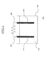
- Fig. 5 is an exemplary view of the power generating device 400 related to the present embodiment of the present invention.
- the power generating device 400 has a structure in which an anode electrode 411 and cathode electrode 413 are arranged at certain intervals on the interior side of a container 430 and is filled with fuel 470.
- Wiring 450 is connected to the anode electrode 411 and cathode electrode 413 and electrical energy is extracted from the power generating device 400.
- the container 430 and wiring 450 can each be formed using a known material.
- the fuel 470 of the power generating device 400 related to the present embodiment is selected from grape sugar (glucose), fruit sugar (fructose), alcohol such as methanol or ethanol, lactic acid or sucrose.
- the fuel which can be used is not limited to these however, anything can be used as long as it can be used as the substrate of the anode electrode enzyme and cathode electrode enzyme explained in the first embodiment.
- the anode electrode 411 and the cathode electrode 413 can be formed for example by winding the wiring 450 around the carbon nanotube film 100.
- Fig. 6 shows an electrode of the power generating device 400 shown in Fig. 5 related to the present embodiment.
- the fuel 470 is immersed in a carbon nanotube film and the included enzyme 120 generates electrical energy with the fuel 470 as a substrate.
- the carbon nanotube film includes flexibility it is possible to wind the film on the wiring 450 and the film functions as an electrode in the power generating device 400.
- the anode electrode 411 and the cathode electrode 413 can be formed by winding the carbon nanotube film 100 on the wiring 450 and drying in an atmosphere under room temperature. It is possible to use the carbon nanotube film 100 and carbon nanotube film 200 explained in the first embodiment as the carbon nanotube film used in the electrode of the power generating device 400 of the present embodiment. In the case where the carbon nanotube film 100 is used, the film may be wound on the wiring 450. However, in the case where the carbon nanotube film 200 is used, the carbon nanotube film is moistened using the buffer solution described above and wound on the wiring 450. After the carbon nanotube film is attached to a base material such as the wiring 450, the film is maintained in a state where the protein 120 is included without widening the intervals within the CNT 111 even when immersed in a solution.
- the power generating device of the present invention related to the present embodiment it is possible to form a flexible, free standing film used in an electrode, in which an enzyme is included in a high orientation carbon nanotube aggregate with excellent electrical conductivity. Because the carbon nanotube film related to the present embodiment is provided with both mechanical strength and flexibility, it is possible attach or wind the film to a substrate material or wiring and provide a flexible power generating device formed only with a safe and clean organic material
- the carbon nanotube film off the present invention explained in the first embodiment can obtain electrical energy using an oxidation-reduction reaction of a fuel as explained in the second embodiment.
- the carbon nanotube film of the present invention can be applied to a biosensor which detects a substance to be tested by detecting an oxidation-reduction current.
- grape sugar glucose
- fruit sugar fructose
- ethanol lactic acid or sucrose etc
- lactic acid or sucrose lactic acid or sucrose etc
- the substance to be measured is not limited to these however and can be any substance which becomes the substrate of an included enzyme.
- the biosensor of the present invention related to the present embodiment it is possible to form a flexible, free standing film used in a sensor, in which an enzyme is included in a high orientation carbon nanotube aggregate with excellent electrical conductivity. Because the carbon nanotube film related to the present embodiment is provided with both mechanical strength and flexibility, it is possible attach or wind the film to a substrate material or wiring and provide a flexible biosensor formed only with a safe and clean organic material
- the CNT 111 which forms the carbon nanotube aggregate 110 related to the present example is synthesized using the super growth method described above. An aggregate of the synthesized CNT 111 is peeled from a silicon substrate using tweezers and the carbon nanotube aggregate 110 is obtained.
- the carbon nanotube film 100 included a CNT 111 length of 1mm, CNT 111 interval of 16nm, sheet resistance of 1.74 ⁇ /cm 2 or more in a perpendicular direction and 2.61 ⁇ /cm 2 or more in a parallel direction and other characteristics were in the range shown in the first embodiment described above.
- the carbon nanotube aggregate 110 peeled from the silicon substrate is held between reverse type tweezers.
- the carbon nanotube aggregate is immersed in a buffer solution containing 1% of a surfactant (Triton X-100) and deaerated for 30 minutes in a vacuum chamber ( ⁇ 1 MPa). It is possible to sufficiently include an enzyme in the carbon nanotube aggregate via this deaeration process.
- the aggregate anchored with tweezers is immersed in 1ml of an enzyme solution (anode: D-fructose Dehydrogenese 10 mg/ml, cathode: Laccase 4.3 ⁇ M, Mcllvaine Buffer (pH 5.0) is used for the buffer solution).
- an enzyme solution anode: D-fructose Dehydrogenese 10 mg/ml, cathode: Laccase 4.3 ⁇ M, Mcllvaine Buffer (pH 5.0) is used for the buffer solution.
- the carbon nanotube aggregate is cleaned by blotting with a
- the carbon nanotube aggregate 110 peeled from the silicon substrate is held between reverse type tweezers.
- the carbon nanotube aggregate is immersed in a buffer solution containing 1% of a surfactant agent (Triton X-100) and deaerated for 30 minutes in a vacuum chamber ( ⁇ 1 MPa). It is possible to sufficiently include an enzyme in the carbon nanotube aggregate via this deaeration process.
- Triton X-100 Triton X-100
- the carbon nanotube aggregate held by the tweezers is immersed in a vial containing 1 ml of an enzyme solution (anode: D-fructose Dehydrogenese 0.5 mg/ml, cathode: Laccase 4.3 ⁇ M, Mcllvaine Buffer (pH 5.0) is used for the buffer solution) and a stirrer so that the aggregate does not interfere with the stirrer.
- an enzyme solution anode: D-fructose Dehydrogenese 0.5 mg/ml, cathode: Laccase 4.3 ⁇ M, Mcllvaine Buffer (pH 5.0) is used for the buffer solution
- Mcllvaine Buffer pH 5.0
- the carbon nanotube aggregate is immersed for 12 hours while stirring the solution at 4°C.
- the carbon nanotube aggregate within the solution was blotted using a pipette.
- the carbon nanotube aggregate was cleaned by pouring out into 10 ml of the buffer solution (Mcllvaine Buffer (
- the carbon nanotube aggregate is cleaned, it is poured onto carbon paper (abbreviated to CP below) and constricted by drying in an atmosphere at room temperature.
- the carbon nanotube film constricted by the drying process was observed using an optical microscope.
- a carbon nanotube film 201 with only a buffer solution which does not contain the enzyme 120, a carbon nanotube film 210 containing Laccase (LAC) as the enzyme 120 and a carbon nanotube film 230 containing D-fructose Dehydrogenese (FDH) as the enzyme 120 were each constricted by the drying process and the carbon nanotube film 200 (solid) was obtained.
- Fig. 7 it can be seen that the constriction rate of the carbon nanotube film changes depending on the size of the contained enzyme.
- the evaluation results of the conduction capabilities of a carbon nanotube film are shown below.
- the evaluation of the conduction capabilities of a carbon nanotube film was performed using an anode which oxidizes a fuel and a cathode which reduces an enzyme.
- the capacitance of the carbon nanotube aggregate was evaluated in order to estimate the permitted amount of an enzyme which can be included.
- the carbon nanotube film 101 (as grown) which is not constricted is used as the first example and the carbon nanotube film 201 (solid) which is constricted is used as the second example.
- a non-orientated CNT is used as an electrode as a comparative example
- a non-orientated CNT 910 with a length of 1 mm is used in comparative example 1
- a non-orientated CNT 920 with a length of 2 ⁇ 5 ⁇ m is used in comparative example 2.
- Example 1, example 2, comparative example 1 and comparative example 2 are each prepared as follows.
- An electrode was prepared for measuring the capacitance of the carbon nanotube film 101 and the carbon nanotube film 201.
- a carbon nanotube aggregate extending n a perpendicular direction from a silicon substrate was peeled using tweezers and immersed in DMF (N, N-dimenthylformide, manufactured by Sigma).
- the carbon nanotube aggregate was blotted with a pipette, placed on a gold electrode (electrode area of 0.01 cm 2 ) prepared on a glass substrate and the carbon nanotube aggregate (as grown) was prepared by drying in an atmosphere at room temperature.
- the carbon nanotube aggregate solid was immersed in the DMF, the aggregate was poured on carbon paper, constricted by drying in an atmosphere at room temperature and placed on a gold electrode (electrode area of 0.01 cm 2 ) using tweezers. The DMF was dripped and dried in an atmosphere at room temperature. A CNT (length: 1 mm) which disperses the carbon nanotube aggregate using an ultrasonic homogenizer and a CNT (length: 2 ⁇ 5 ⁇ m) which similarly disperses a commercially available CNT was used as the non-orientated CNT. DMF was used to prepare the electrode and 90ng/ ⁇ l of a CNT solution was prepared.
- the CNT solution was subjected to ultrasound for 15 minutes at 10W using an ultrasonic homogenizer (Sonifier 250D BRANSON) and the CNT was dispersed. 2.6 ⁇ l of the dispersed solution was dripped onto the gold electrode and dried for 1.5 hours in a vacuum oven at 80°C. These electrodes were observed using an electron microscope ( Fig. 8 (a) ).
- the capacitance volume was calculated by measuring impedance Z and frequency f using a current impedance method, and inserting into the formula (1).
- C 1 / 2 ⁇ ⁇ fz
- An electrochemical measurement system (Electrochemical Analyzer Model 600S, manufactured by BAS) was used as the measuring instrument and an alternating electric field of ⁇ 5 mV and a frequency of 1 Hz ⁇ 1 X 10 5 Hz in a buffer solution (Mcllvaine Buffer (pH 5.0)) were used as the measurement conditions.
- Capacitance volume using alternating current impedance is shown in Fig 8 (b) . It can be seen that a volume of the film of the carbon nanotube aggregate in example 1 and example 2 was more than twice compared to the non-orientated CNT in comparative example 1 and comparative example 2. In addition, it can be seen that there was no significant difference in the capacitance volume of the carbon nanotube aggregate before or after constriction.
- an anode electrode was prepared and its capabilities were evaluated.
- a film 510 of a carbon nanotube aggregate which is not constricted using a static inclusion method was prepared as example 3
- a carbon nanotube film 520 which is not constricted using a stirring inclusion method was prepared as example 4
- a carbon nanotube film 530 which is constricted using a stirring inclusion method was prepared as example 5.
- a 1mm long non-orientated CNT 910 was used as comparative example 3 and a 2 ⁇ 5 ⁇ m long non-orientated CNT 920 was used as comparative example 4.
- anode electrode was prepared using a carbon nanotube film
- the film was placed on a gold electrode (electrode area of 0.01 cm 2 ) and a buffer solution was dripped onto the electrode. After drying the film was attached to the electrode and a carbon nanotube film electrode was prepared.
- An enzyme was incorporated into the non-orientated CNT electrode in the comparative examples by dripping an enzyme solution (D-fructose Dehydrogenese 10mg/ml) on the electrode prepared by the method explained in the evaluation of capacitance volume.
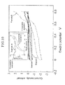
- a current, potential curve of fructose oxidation is shown in Fig. 9 .
- the current, potential curve was obtained by a three electrode method (working: enzyme electrode, reference: Ag/AgCl sat. KCI, counter: platinum) using an electrochemical measurement system (Electrochemical Analyzer Model 600S, manufactured by BAS). The measurement conditions were a sweep velocity of 10 mV/s at room temperature in 200 mM of a fructose solution
- the non-orientated CNTs in comparative example 3 and comparative example 4 had about the same current density.
- the carbon nanotube film 510 which is not constricted using the static inclusion method in example 3 showed a significantly larger current density compared to the comparative examples.
- the carbon nanotube film 520 which is not constricted using the stirring inclusion method in example 4 showed about 20 times the current density compared to the comparative examples and the carbon nanotube film 530 which is constricted using the stirring inclusion method in example 5 showed an excellent current density of about 40 times compared to the comparative examples.
- example 4 and example 5 show a maximum current of about the same value, the current density was the largest in example 5 given the amount of constriction. This suggests that no drop in enzyme activity due to constriction of a carbon nanotube film is observed.
- a cathode electrode was prepared and its capabilities were evaluated.
- a carbon nanotube film 510 which is not constricted using a static inclusion method was prepared as example 7
- a carbon nanotube film 520 which is not constricted using a stirring inclusion method was prepared as example 8
- a carbon nanotube film 530 which is constricted using a stirring inclusion method was prepared as example 9.
- a 1mm long non-orientated CNT 910 was used as comparative example 5 and a 2 ⁇ 5 ⁇ m long non-orientated CNT 920 was used as comparative example 6.
- the same method used for preparing the anode electrode described above was used as the preparation method of each electrode.
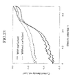
- An enzyme reduction current, potential curve is shown in Fig. 10 .
- the current, potential curve was obtained using a device which is used in the evaluation of the anode electrode capabilities, under the same conditions and under enzyme neutral conditions.
- the current, potential curve was the same as the result obtained in the evaluation of the anode electrode capabilities and the non-orientated CNT in comparative example 5 and comparative example 6 had about the same current density.
- the carbon nanotube film 510 which is not constricted using the static inclusion method in example 7 showed a significantly larger current density compared to the comparative examples.
- the carbon nanotube film 520 which is not constricted using the stirring inclusion method in example 8 showed about 20 times the current density compared to the comparative examples and the carbon nanotube film 530 which is constricted using the stirring inclusion method in example 9 showed an excellent current density of about 60 times compared to the comparative examples.
- example 8 and example 9 show a maximum current of about the same value, the current density was the largest in example 9 given the amount of constriction. This suggests that no drop in enzyme activity due to constriction of a carbon nanotube film is observed.
- a bio-power generating device was prepared using the constricted carbon nanotube film 530 using the stirring inclusion method in example 5 and example 9 described above, different external resistors (10 k ⁇ ⁇ 2 M ⁇ ) were connected between electrodes, a voltage at this time was measured using an electrochemical measurement system (Electrochemical Analyzer Model 600S, manufactured by BAS) and current and output were measured. The measurement conditions were 200 mM of an oxygen saturated fructose solution. The results are shown in Fig. 11 . It was possible to obtain a maximum output density of 19 ⁇ W/cm 3 at a voltage of 0.61 V using the bio-power generating device related to the present example.
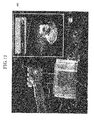
- the carbon nanotube film described above was wound onto a wire electrode and a lighting test of an LED was performed.
- a condenser (1 ⁇ F) and a red LED were bonded to a charge pump IC S-882Z20, manufactured by Seiko Instruments).
- the assembled device was sealed using Polydimethylsiloxane (PDMS).
- the LED device related to the present example is shown in Fig. 12 .
- the carbon nanotube film 200 was wound onto a gold wire 450 (diameter 0.2 mm) extending from the device.
- the carbon nanotube film prepared the same as in the example described above was moistened in a buffer solution and wound onto the wire 450 using tweezers. After drying in an atmosphere under room temperature, 200 mM of a fructose solution was filled into a container 430 as a fuel 470 and lighting of the LED was confirmed by immersing the gold wire 450 in the fuel 470.
- FIG. 9 and Fig. 10 An example of a biosensor of the present invention explained in the third embodiment is shown in Fig. 9 and Fig. 10 . It is possible to evaluate Fig. 9 and Fig. 10 as a biosensor using the carbon nanotube films in each example and the non-orientated CNT in the comparative example. That is, each example and comparative example shows a biosensor which detects fructose in Fig. 9 and oxygen in Fig. 10 .
- example 6 in Fig. 9 is an example of detecting a buffer solution which not include fructose using the carbon nanotube film 520 which is not constricted using the stirring inclusion method in example 4
- an example 10 in Fig. 10 is an example of detecting a buffer solution in which nitrogen (N 2 ) is saturated using the carbon nanotube film 520 which is not constricted using the stirring inclusion method in example 8. From this result it can be seen that the carbon nanotube film related to the present invention of the present example functions as a highly sensitive biosensor.
- the carbon nanotube film related to the present invention a theoretical evaluation of the included amount of fructose dehydrogenase, (FDH, molecular weight: ca. 140kDa) in a carbon nanotube aggregate 110 (1 mm x 12 ⁇ m x 1mm) was performed.
- FDH fructose dehydrogenase
- the carbon nanotube aggregate 110 included CNTs 111 with a diameter of 2.8 mm arranged at intervals of 16 nm with multiple spaces existing therein.
- H 1.0 mm (CNT length)
- R 7.0 x 10 -6 mm (FDH diameter)
- S 12 x 10 -3 mm 2 (bottom surface area of the carbon nanotube aggregate 110)
- U 2.6 x 10 -10 mm 2 (bottom surface area of a space enclosed by a 16 nm interval).
- FDH fructose dehydrogenase
- a carbon nanotube aggregate 110 (1 mm x 12 ⁇ m x 1mm) was performed by way of experiment.
- the amount of included FDH was measured using a Protein Quantitation Kit (C-6667, manufactured by Molecular Probes).
- Inclusion of an enzyme in the carbon nanotube aggregate 110 was performed using the stirring method shown previously.
- the carbon nanotube aggregate (CNTF) included with an enzyme was immersed in a sodium phosphate water solution (including 0.1 M sodium borate, 1% of sodium cholate, pH 9.3) and dispersed using an ultrasonic homonegizer.
- CBQCA was labeled on the FDH using 5 mM (3-(4-carboxybenzoyl)-quinoline-2-carboxaldehyde (ATTO-TAG CBQCA) referred to below as CBQCA) and 20 mM KCN.
- the fluorescence intensity was measured following 1.5 hours of incubation and the amount of FDH was calculated from a calibration curve calculated in advance.
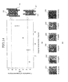
- Fig. 14 (a) The measurement results are shown in Fig. 14 (a) .
- the amount of enzyme included in the carbon nanotube film 100 increased with an increase in the immersed enzyme concentration.
- the constriction of the carbon nanotube film 200 was controlled with an increase in the included amount of the enzyme. That is, it is possible to control the included amount of an enzyme in a carbon nanotube film by the concentration of an immersed enzyme.
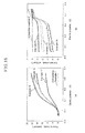
- Fig. 15 shows the relationship between the concentration of an immersed enzyme and current density. From the results in Fig. 15 , the current density of the carbon nanotube film was largest in both example 11 and example 12 under a condition where FDH was included in the carbon nanotube aggregate 110 with an enzyme concentration of 3 mg/ml. As is shown in Fig. 14 (a) , the FDH concentration matched a theoretical value calculated from a model in which FDH were densely arranged in one column parallel to the length direction of the CNT 111 in a space enclosed by 4 CNTs 111 in the carbon nanotube aggregate.
- the current density of the carbon nanotube film dropped when FDH was included in the carbon nanotube aggregate 110 with an excess enzyme concentration which exceeds 3 mg/ml. From this result, it is inferred that the electrode capabilities per unit area dropped when the constriction of the carbon nanotube film is controlled in a drying process and miniaturization of the carbon nanotube film is obstructed when FDH was included in the carbon nanotube aggregate 110 with an excess enzyme concentration which exceeds 3 mg/ml. In addition, it is inferred that inclusion of FDH at an excessive enzyme concentration causes changes in the orientation of an enzyme included in the carbon nanotube film and a drop in electrode capabilities due to a loss of activity of the enzyme.
- electrode capabilities become optimum per unit area by including a structure in which the enzyme 120 is arranged in one column in a parallel direction to the length direction of the CNT 111 in a space enclosed by 4 CNTs 111 of the carbon nanotube aggregate. It is possible to optimize electrode capabilities in the carbon nanotube film related to the present invention by adjusting the concentration of immersed enzyme.
- Durability of an enzyme electrode was evaluated using a carbon nanotube film included with FDH in a 3 mg/ml solution as example 13 and a carbon nanotube film with this constricted as example 14.
- the durability evaluation was performed by measuring an oxidation current (0.2 V, reference: Ag/AgCl) in a Mcllvaine buffer (pH 5.0) including 200 mM fructose and calculating a temporal reduction rate with respect to an initial current.
- oxidation current 0.2 V, reference: Ag/AgCl
- Mcllvaine buffer pH 5.0
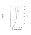
- output current dropped only 25% in example 14. From this result it is inferred that nano-level spaces in the carbon nanotube film constricted by the drying process contributed to enzyme maintenance and activity support.
- Km, app showed 10 ⁇ 1 mM and this matches a value measured when an enzyme is in a bulk state dispersed in a solution. That is, it is clear that enzyme activity is maintained even when the carbon nanotube film related to the present invention is constricted.
- the detection limit of fructose is 10 ⁇ M and a linear correlation is shown with current density at a fructose concentration up to around 50 mM, it is clear that the carbon nanotube film related to the present invention includes excellent capabilities even as a biosensor.
- an cathode was evaluated by preparing two constricted stacked carbon nanotube films as example 18, one constricted carbon nanotube film as example 19, and one non-constricted stacked carbon nanotube film as example 20 which were immersed in 0.25 mg/ml of a solution and included with Laccase, and a Mcllvaine buffer (pH 5.0) with saturated oxygen was used as the measurement solution.
- a Mcllvaine buffer (pH 5.0) saturated with nitrogen was used in the measurement of a non-constricted carbon nanotube film as comparative example 8.
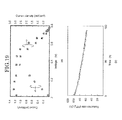
- the evaluation of the battery was performed by measuring an oxidation current (0.2V, reference: Ag/AgCl) in a Mcllvaine buffer (pH 5.0) including 200 mM of fructose and by calculating a temporal reduction rate with respect to an initial power. As is shown in Fig. 19 (b) , the battery in the present example could maintain a power of 80% even after 37 hours had elapsed from the start of the measurement.
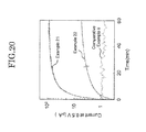
- Fig. 20 shows the oxidation current of a fructose obtained in a three electrode method (working: carbon nanotube electrode, reference: Ag/AgCl sat. KCL, counter: platinum) using an electrochemical measurement system (Electrochemical Analyzer Model 600S, manufactured by BAS), and measured at a constant voltage (0.5V).
- the carbon nanotube aggregate constricted by pre-processing in example 22 held about the same capacitance volume as the carbon nanotube aggregate (example 2) which is not constricted by pre-processing as is shown in Fig. 8 (b) .
- the fructose oxidation current was smaller by single figures.
- the current density of non-orientated CNT in comparative example 9 was smaller again by single digits.
- Fig. 21 shows the oxidation current of a fructose obtained in a three electrode method (working: carbon nanotube electrode, reference: Ag/AgCl sat. KCL, counter: platinum) using an electrochemical measurement system (Electrochemical Analyzer Model 600S, manufactured by BAS), and measured at a constant voltage (0.5V).
- the G/D ratio shows the ratio of a G band and D band in a Raman spectrum and shows higher crystallization (fewer defects) the greater the value.
- the electrode capabilities were better in the carbon nanotube aggregate with the higher G/D ratio.
- a carbon nanotube film in which bilirubin oxidase (BOD) known as multicopper oxidase is used as a catalyst was prepared and capabilities were evaluated.
- BOD bilirubin oxidase
- a carbon nanotube aggregate 110 not constricted by pre-processing was used in a current density evaluation.
- Fig. 22 (a) shows the relationship between concentration of the BOD solution to be immersed in and current density.
- a current value increased in response to an increase in the concentration of the BOD solution and saturated at a BOD concentration of about 0.05 mg/ml or more.
- the appearance of constriction of a carbon nanotube film 250 which includes this BOD was observed using an optical microscope ( Fig.
- the level of constriction depends on the concentration of the BOD solution in which the carbon nanotube film is immersed.
- the constriction of the film saturated at 0.05 mg/ml or more which half an initial area. This matches a model in which BOD size was assume to be about 2 nm and a CNT surface was saturated with the BOD.
- a surfactant on the capabilities of the carbon nanotube film 250 included with BOD was examined.
- An oxidation-reduction current, potential curve is shown in Fig. 23 . It is clear that surface modification of a nanotube by a surfactant is important for the activity of an enzyme. This is assumed to reduce drying out of a water component in the constriction process by modification of the surfactant on the CNT surface which is originally hydrophobic. As a result, a maximum current density of 2.0 mA/cm 2 at 0V vs, Ag/AgCl was obtained.
- a safe, small scale and flexible, free-standing type protein containing carbon nanotube film is provide and and a sensor and power generating device with excellent functions are provided by using the carbon nanotube film.
- carbon nanotube film related to the present invention 101 carbon nanotube film not including an enzyme 110 carbon nanotube film aggregate 120 enzyme 150 flexible substrate 200 carbon nanotube film related to the present invention 201 carbon nanotube film not including an enzyme 210 carbon nanotube film including LAC 230 carbon nanotube film including FDH 250 carbon nanotube film including BOD 400 power generating device related to the present invention 411 anode electrode 413 cathode electrode 430 container 450 wiring 470 fuel 510 carbon nanotube film not constricted using a static inclusion method 520 carbon nanotube film not constricted using a stirring inclusion method 530 carbon nanotube film constricted using a stirring inclusion method 610 carbon nanotube film not constricted including FDH 630 carbon nanotube film constricted including FDH 910 1 mm long non-orientated CNT 920 2 ⁇ 5 ⁇ m long non-orientated CNT
Landscapes
- Chemical & Material Sciences (AREA)
- Engineering & Computer Science (AREA)
- Nanotechnology (AREA)
- Life Sciences & Earth Sciences (AREA)
- Health & Medical Sciences (AREA)
- Organic Chemistry (AREA)
- Materials Engineering (AREA)
- Physics & Mathematics (AREA)
- Chemical Kinetics & Catalysis (AREA)
- Electrochemistry (AREA)
- Molecular Biology (AREA)
- General Physics & Mathematics (AREA)
- Biochemistry (AREA)
- Wood Science & Technology (AREA)
- Zoology (AREA)
- Genetics & Genomics (AREA)
- Bioinformatics & Cheminformatics (AREA)
- General Health & Medical Sciences (AREA)
- Manufacturing & Machinery (AREA)
- General Chemical & Material Sciences (AREA)
- Condensed Matter Physics & Semiconductors (AREA)
- Crystallography & Structural Chemistry (AREA)
- Inorganic Chemistry (AREA)
- Microbiology (AREA)
- Biotechnology (AREA)
- Medicinal Chemistry (AREA)
- Biomedical Technology (AREA)
- General Engineering & Computer Science (AREA)
- Composite Materials (AREA)
- Pathology (AREA)
- Immunology (AREA)
- Analytical Chemistry (AREA)
- Spectroscopy & Molecular Physics (AREA)
- Carbon And Carbon Compounds (AREA)
- Inert Electrodes (AREA)
- Sustainable Development (AREA)
- Sustainable Energy (AREA)
Abstract
Description
- The present invention is related to a protein-enclosed carbon nanotube aggregate (called a Carbon Nanotube Forest; CNTF) free standing film. In particular, the present invention is related to a free standing film of a carbon nanotube aggregate containing a protein such as an enzyme and a sensor and a power generating device used in the film for an electrode and a manufacturing method of the same. Here, a free standing film refers to a film which does not require a support substrate.
- In recent years, beginning with environmental problems power generation devices with a low environmental burden are being demanded. In addition, together with the development circumstances of electronic paper or bio-electronic devices such as health monitoring which are dominant as a near future device, the demand for next generation power generation devices continues to head towards to conventional safety and light weight as well as clean, flexible and small scale devices. Given these circumstances, since a biofuel cell which generates power using a fuel derived from living matter also includes much appeal (close biofuel (sugars, alcohol), mild operating environment (normal temperature, neutrality, atmosphere), unnecessary fuel refinement and unnecessary separator etc), they are attracting attention worldwide.
- A biofuel cell is a type of fuel cell which includes a structure in which an enzyme which oxidizes a fuel derived from living matter is fixed to an anode electrode, an enzyme which reduces an enzyme is fixed to a cathode electrode and electrical energy is obtained from a fuel derived from living matter using an oxidation reduction reaction by these enzymes.
- However, there are many problems in the material, components and packaging technology of a biofuel cell derived from a chemical battery or a biosensor. Because an electrode material with carbon as constituent element has excellent safety, durability and biocompatibility, it is used widely in sensors or batteries and is usually attached to carbon fine particles using a binder. For example, a procedure in which low temperature firing carbon fine particles are adsorbed on an electrode and an enzyme is fixed to the inner space or external surface of the fine particles is reported in
patent document 1. However, pore size in which matches the size of a protein can't be controlled and there is no flexibility. In addition, enzyme fixing to a carbon nanotube aggregate orientated in a perpendicular direction on a substrate is previously reported by the inventors inpatent document 2 or innon-patent document 1, and an enzyme modification to a carbon nano-fiber is reported innon-patent document 2. However, in each of these reports the carbon nanotube aggregate integrally formed with a support and does not contain flexibility. -
- Patent Document 1: Japanese Laid Open Patent
2007-34537 - Patent Document 2: Japanese Laid Open Patent
2009-222459 - Non-Patent Documents
-
- Non-Patent Document 1: Chow Khim Tan, Kian Ping Loh, Thong T. L John, Analyst, 133 (2008) 448
- Non-Patent Document 2: Eugenii Katz, Itamar Willner, ChemPhysChem, 5 (2004) 1084.
- If capabilities such as safety, small scale and flexibility can be provided to an electrode, the design freedom of a power generating device can be improved and the performance of a battery is advanced. In addition, these electrode capabilities are commonly demanded for a biosensor and significantly contribute to the development of biosensors.
- The present invention answers the demands of power generating devices and biosensor development and provides a flexible, free-standing type protein containing carbon nanotube film, and a sensor and power generating device each equipped with the carbon nanotube film as an electrode.
-
- (1) According to the present invention a carbon nanotube film is provided including a carbon nanotube aggregate formed by aggregating a plurality of carbon nanotubes, and a plurality of enzymes included between the plurality of carbon nanotubes.
-
- (2) The carbon nanotube film may include a different protein to the enzyme.
-
- (3) The carbon nanotube film may include a surfactant agent between the plurality of carbon nanotubes.
-
- (4) The carbon nanotube film according to
claim 1, wherein a plurality of mediator molecules is included between the plurality of carbon nanotubes. -
- (5) The enzyme may be oxidase or a dehydrogenase.
-
- (6) The carbon nanotube aggregate may include a surface area of 600 m2/g or more and 2,600 m2/g or less, a weight density of 0.002 g/cm3 or more and 0.2 g/cm3 or less, and a pore size distribution maximum of 5nm or more and 100nm or less.
-
- (7) A part may be included in which the enzyme is arranged in one column in a parallel direction to a length direction of the carbon nanotube at a space enclosed by 4 of the carbon nanotubes of the carbon nanotube aggregate.
-
- (8) In addition, according to the present invention a fuel cell is provide including a pair of electrodes including the carbon nanotube film according to any one of (1) to (7) and a fuel.
-
- (9) In addition, according to the present invention a sensor is provided including an electrode including the carbon nanotube film according to any one of (1) to (7).
-
- (10) In addition, according to the present invention a method of manufacturing a carbon nanotube film is provided including peeling a carbon nanotube film including a plurality of carbon nanotubes grown on a substrate from the substrate, and immersing the carbon nanotube film in a solution including an enzyme.
-
- (11) In the method of manufacturing the carbon nanotube film, after peeling the carbon nanotube film from the substrate the carbon nanotube film may be immersed in a first buffer solution including a surfactant and next the carbon nanotube film may be immersed in the solution including the enzyme.
-
- (12) In the method of manufacturing the carbon nanotube film after the carbon nanotube film is immersed in the solution the carbon nanotube film may be dried.
-
- (13) In the method of manufacturing the carbon nanotube film the solution may include a different protein to the enzyme.
-
- (14) In the method of manufacturing the carbon nanotube film a plurality of mediator molecules may be included in the solution.
-
- (15) In the method of manufacturing the carbon nanotube film the enzyme may be an oxidase or a dehydrogenase.
-
- (16) In the method of manufacturing the carbon nanotube film the solution including the enzyme may be a concentration including a part in which the enzyme is arranged in one column in a parallel direction to a length direction of the carbon nanotube at a space enclosed by 4 of the carbon nanotubes of carbon nanotube aggregate.
- According to a method of the present invention, a safe, small scale and flexible, free-standing type protein containing carbon nanotube film, and a sensor and power generating device each equipped with the carbon nanotube film as an electrode are provided.
-
-
Fig. 1 is an exemplary view of acarbon nanotube film 100 related to one embodiment of the present invention, (a) is a perspective view and (b) is an upper surface view. -
Fig. 2 is an exemplary view of acarbon nanotube film 200 related to one embodiment of the present invention, (a) is a perspective view and (b) is an upper surface view. -
Fig. 3 shows a manufacturing method of a carbon nanotube film related to one embodiment of the present invention. -
Fig. 4 shows an example whereby thecarbon nanotube film 100 related to one embodiment of the present invention is attached to aflexible substrate 150, (a) is an optical photograph and (b) is an exemplary view. -
Fig. 5 is an exemplary view of apower generating device 400 related to one embodiment of the present invention. -
Fig. 6 shows an electrode of thepower generating device 400 related to one embodiment of the present invention, (a) shows an optical photograph and an exemplary view of thecarbon nanotube film 100 and (b) is an exemplary view and optical photograph of the electrode. -
Fig. 7 shows the relationship between the size of a contained enzyme and the size of thecarbon nanotube film 100 after drying related to one example of the present invention. -
Fig. 8 shows the result of a capacitance evaluation in the examples and comparative examples (a) shows an electron microscopic image (SEM image) of a carbon nanotube film and (b) shows the result of the capacitance evaluation. -
Fig. 9 shows a current, potential curve of fructose oxidation by an anode electrode in the examples and comparative examples. -
Fig. 10 shows a current, potential curve of oxygen reduction by a cathode electrode in the examples and comparative examples. -
Fig. 11 shows an output evaluation result of a bio power generation device. -
Fig. 12 shows an LED device related to one example of the present invention. -
Fig. 13 is an exemplary view showing a theoretical spatial arrangement between acarbon nanotube aggregate 110 and an enzyme 120 (a) is an upper surface view and (b) is a perspective view. -
Fig. 14 shows an actual measurement result of the amount of contained enzyme (a) shows the relationship between enzyme concentration and the amount of contained enzyme and (b) is optical microscopic image. -
Fig. 15 shows the relationship between enzyme concentration and current density. -
Fig. 16 shows the result of a durability evaluation of an enzyme electrode. -
Fig. 17 shows the relationship between fructose concentration and current density. -
Fig. 18 shows the relationship between a stacked carbon nanotube film and electrode capabilities (a) shows a measurement result of an anode and (b) shows a measurement result of a cathode. -
Fig. 19 shows a result of capabilities evaluation of a battery (a) shows a measurement result output with respect to a voltage of the battery and current density and (b) shows the result of a durability experiment. -
Fig. 20 shows the effects on electrode capabilities by the structure of a carbon nanotube film. -
Fig. 21 shows the relationship between the G/D ratio of a carbon nanotube film and electrode capabilities. -
Fig. 22 (a) shows the capabilities of a cathode which uses bilirubin oxidase as an electrode catalyst and (b) shows the relationship between the concentration of a bilirubin oxidase solution and contraction of a carbon nanotube aggregate. -
Fig. 23 shows the effects of a surfactant agent on electrode capabilities. - A protein containing carbon nanotube film, and a sensor and power generating device each equipped with the carbon nanotube film as an electrode related to the present invention and a method of manufacturing the same are explained below while referring to the diagrams. The protein containing carbon nanotube film, sensor and power generating device each equipped with the carbon nanotube film as an electrode related to the present invention includes an electrode which includes a carbon nanotube aggregate. The protein containing carbon nanotube film, sensor and power generating device each equipped with the carbon nanotube film as an electrode related to the present invention and method of manufacturing the same should not be interpreted as being limited to the descriptive content of the embodiments and examples shown below. Furthermore, in the diagrams which are referred to by the present embodiment and the examples described herein, the same reference symbols are attached to the parts having the same or similar functions and therefore repeating explanations are omitted.
- The inventors of the present invention made keen examinations for realizing a safe, small scale and flexible, free-standing type protein containing carbon nanotube film, and a sensor and power generating device each equipped with the carbon nanotube film as an electrode. As a result, the inventors arrived at providing a flexible carbon nanotube film with improved battery capabilities, a sensor and power generating device each equipped with the carbon nanotube film as an electrode by fixing a fragile enzyme to a carbon nanotube aggregate which is an excellent conductive material using a mild fixing method.
- The inventors of the present invention conducted research into a CNT structure having a high orientation using a Chemical Vapor Deposition method (referred to as CVD below), for example, they reported on a single-walled CNT structure and manufacturing method thereof in Science 306, 1362-1364 (2004) and International Published Patent
WO2006/011655 . In addition, they also reported on double-walled CNT (referred to as double-walled CNT below) structures and manufacturing method thereof inNature Nanotechnology 1, 131-136 (20062007-145634 - The inventors of the present invention reported in
Patent Document 2 of realizing a highly efficient hydrogen generating device by making it possible for an electrode material in which an oxidation-reduction protein is fixed to an aggregate of an orientated single-walled CNT formed on a semiconductor substrate using the CVD (referred to as supper growth method below) described above, to efficiently accept electrons between the CNT and the oxidation-reduction protein. However, because a conductive substrate is used inPatent Document 2, further improvement is necessary to realize a small scale and flexible free-standing carbon nanotube film. - An exemplary view of a
carbon nanotube film 100 related to an embodiment of the present invention is shown inFig. 1 . Thecarbon nanotube film 100 includes a structure in which acarbon nanotube aggregate 110 aggregated with aCNT 111 contains aprotein 120. In other words, theprotein 120 exists amongCNT 111 which forms thecarbon nanotube aggregate 110 aggregated with theCNT 111. A protein (enzyme) which includes redox activity is used as theprotein 120. However, an inactive protein or a protein which does not obstruct a reaction of a protein which includes redox activity may also be included. - It is preferred that an orientated single-walled CNT is used as the
CNT 111 which forms thecarbon nanotube aggregate 110 related to the present embodiment. TheCNT 111 can be synthesized using the super growth method mentioned above. It is possible to obtain thecarbon nanotube aggregate 110 by peeling an aggregate of the synthesizedCNT 111 from a synthetic substrate. - The relative surface area of the
carbon nanotube aggregate 110 used in thecarbon nanotube film 100 is preferred to be 600 m2/g or more and 1,300 m2/g or less if unopened single-walled CNTs are mainly present. The relative surface area of thecarbon nanotube aggregate 110 used in thecarbon nanotube film 100 is preferred to be 1,300 m2/g or more and 2,600 m2/g or less if opened single-walled CNTs are mainly present. It is possible to calculate the relative surface area of a carbon nanotube aggregate by measuring an absorption/desorption isotherm curve at 77K of liquid nitrogen. Sheet resistance of thecarbon nanotube aggregate 110 is 1.74 Ω/cm2 or more in a perpendicular direction and 2.61 Ω/cm2 or more in a parallel direction. In addition, weight density of thecarbon nanotube aggregate 110 is 0.002 g/cm3 or more and 0.2 g/cm3 or less. - In the present embodiment, the
carbon nanotube aggregate 110 used in thecarbon nanotube film 100, for example, as typical values, has a single-walled CNT contained ratio of 98% or more (ratio of the number of single-walled CNTs with respect to double layer CNTs and multi-layer CNTs calculated from a transmission type electron microscope image of the carbon nanotube aggregate), a pore size distribution maximum of 5nm or more and 100nm or less, metal impurities of 0.01 mass % or less, a carbon purity of 99.9 mass % or more, a G/D ratio of 50 or less, an average external diameter of 1.5nm or more and 4nm or less, a half value width of 1nm, and a Herman orientation factor of 0.1 or more and 1 or less. - It is preferred that the
enzyme 120 used in thecarbon nanotube film 100 related to the present embodiment is an oxidase such as dehydrogenase, or for example, a combination of diaphorase and glucose dehydrogenase, or selected from enzymes such as glucose oxidase, fructose oxidase, fructose dehydrogenase, alcohol oxidase, alcohol dehydrogenase, lactate oxidase or lactate dehydrogenase as the enzyme included in an anode electrode. The enzyme which can be used in the anode electrode is not limited to these. For example, any enzyme can be used as long as the enzyme is useful in the degradation of a biomass fuel such as sugar or alcohol. - In addition, it is preferred that an enzyme with oxygen such as oxidase as the substrate, for example, an enzyme such as a multicopper oxidase such as bilirubin oxidase or laccase is used as the enzyme included in an cathode electrode. However, the enzyme which can be used in the cathode electrode is not limited to these. For example, any enzyme can be used as it is useful in oxidation-reduction.
- The manufacturing method of a carbon nanotube film described above is explained below. The carbon nanotube film is manufactured by including the
enzyme 120 in thecarbon nanotube aggregate 110. Because thecarbon nanotube aggregate 110 contains a very high level of hydrophoby, including theenzyme 120 in thecarbon nanotube aggregate 110 is not easy. The inventors of the present invention discovered a method for including an enzyme in thecarbon nanotube aggregate 110 after repeated trial and error. Specifically, since a biomolecule has a fragile structure it is necessary to consider the mildness of a process in an inclusion and contraction process. This means that it is impossible to realize this if the materials used in the constriction process of the free-standing film proposed in the present application and the conditions are not together. There are two methods that can be used as an inclusion method, a method of immersing a carbon nanotube aggregate in a static enzyme solution and a method of immersing a carbon nanotube aggregate in a stirred enzyme solution. In addition, it is possible to reduce the size of thecarbon nanotube film 100 by constricting the carbon nanotube aggregate by drying after including theenzyme 120 in thecarbon nanotube aggregate 110. The carbon nanotube film before construction is called "as grown" and the carbon nanotube film after constriction is called "solid" below. -
Fig. 3 shows a manufacturing method of thecarbon nanotube film 100 related to the present embodiment. The carbon nanotube aggregate related to the present embodiment can be manufactured using the supper growth method (International Published PatentWO2006/011655 ) reported by the inventors. A manufacturing process of thecarbon nanotube film 100 can include a carbon nanotube aggregate peeling process, pre-processing and an enzyme inclusion process, and a drying process additionally. The carbon nanotube aggregate peeling process is a process of peeling a sheet shapedcarbon nanotube aggregate 110 from a highly orientated CNT aggregate synthesized on a synthetic substrate. Even if the carbon nanotube aggregate is peeling, catalyst particles formed on a synthetic substrate for synthesizing thecarbon nanotube aggregate 110 are almost never peeled from the top of the synthetic substrate. As a result, in the carbon nanotube aggregate peeling process it is possible to obtain a highly purecarbon nanotube aggregate 110 without including hardly any catalyst particles in thecarbon nanotube aggregate 110. - The pre-processing process is for immersing the peeled
carbon nanotube aggregate 110 in a buffer solution for a certain period of time under reduced pressure conditions. By reducing pressure, any gas remaining within thecarbon nanotube aggregate 110 is deaerated. Thecarbon nanotube aggregate 110 is sufficiently deaerated in order to easily immerse a solution which includes theenzyme 120 in thecarbon nanotube aggregate 110 in the next enzyme inclusion process. It was discovered that it is possible to realize sufficiently including an enzyme into a carbon nanotube aggregate via this deaeration process. A surfactant may also be added to the buffer solution. In addition, an ionic liquid may be used instead of a surfactant. Because a CNT is hydrophobic it is possible to increase the affinity to water by adding a surfactant. In addition, thecarbon nanotube aggregate 110 forms a free-standing type carbon nanotube film by immersing a water component among theCNT 111. - TritonX-100,
Tween 20 etc or any surfactant that does not affect the activity of theenzyme 120 can be used as the surfactant used in the pre-processing process of thecarbon nanotube aggregate 110 related to the present embodiment. In addition, any buffer solution may be used as the buffer solution as long as it does not affect the activity of theenzyme 120 such as phosphate buffered saline, PBS, or Mcllvaine buffer solution. - Next, the
enzyme 120 is included in thecarbon nanotube aggregate 110 using an enzyme inclusion process. In the enzyme inclusion process thecarbon nanotube aggregate 110 is immersed in an enzyme solution for a certain period of time. Following this, thecarbon nanotube aggregate 110 containing theenzyme 110 is washed using a buffer solution and the carbon nanotube film 100 (as grown) is obtained. Here, the enzyme inclusion process can be performed using a static inclusion method or a stirring inclusion method. - The static inclusion method is a method for including the
enzyme 120 by leaving thecarbon nanotube aggregate 110 to stand for a certain period of time within the enzyme solution. In addition, the stirring inclusion method is a method for including theenzyme 120 by immersing thecarbon nanotube aggregate 110 for a certain period of time in a stirred enzyme solution. While it is possible to use either the static inclusion method of the stirring inclusion method in the enzyme inclusion process, as is shown in the examples described below, the stirring inclusion method can include theenzyme 120 in thecarbon nanotube aggregate 110 more efficiently compared to the static inclusion method. In addition, in the enzyme inclusion process, it is possible to adjust the amount of included enzyme in a carbon nanotube aggregate by changing the concentration of the enzyme solution. - The
carbon nanotube film 100 containing theenzyme 100 may further be dried by a drying process. When thecarbon nanotube film 100 is dried in an atmosphere under room temperature on carbon paper (abbreviated to CP herein), thecarbon nanotube film 100 constricts. By drying thecarbon nanotube film 100 it is possible to produce a small scale free standing type film. In addition, as is shown inFig. 2 , when thecarbon nanotube film 100 constructs due to drying, the intervals among theCNT 111 become narrower to the extent of the containedenzyme 120. In this way, as is shown inFig. 2 , it is possible to provide a carbon nanotube film 200 (solid) with a high reaction density by efficiently contacting theCNT 111 andenzyme 120. - In addition, while the size of the intervals among the
CNT 111 become the extent of the containedenzyme 120 when thecarbon nanotube film 200 constricts due to drying, it is also possible to simultaneously include a different type of protein with different sized molecules to theenzyme 120. For example, in the case of including a protein which is larger than theenzyme 120 and does not obstruct inactivity or an enzyme reaction of theenzyme 120, it is possible to provide a place for a reaction in order to improve the reaction efficiency of theenzyme 120 within thecarbon nanotube film 200. - In the present embodiment, a mediator may further be included in the carbon nanotube film. A known mediator may be used as the mediator.
- Because the
carbon nanotube films Fig. 4 shows an example where a carbon nanotube film is attached to aflexible substrate 150. For example it is possible to use Polyethylene Terephthalate (PET) or a collagen gel as theflexible substrate 150 related to the present invention. After theenzyme 120 is included using the enzyme inclusion method described above, thecarbon nanotube film 100 is placed on theflexible substrate 150 and dried under an atmosphere at room temperature. In addition, in the case where thecarbon nanotube film 200 is attached to theflexible substrate 150, the carbon nanotube film is moistened using the buffer solution described above and attached to theflexible substrate 150. After a carbon nanotube film is attached to a base material such as thesubstrate 150, the film is maintained in a state where theprotein 120 is included without widening the intervals within theCNT 111 even when immersed in a solution. - As is shown in
Fig. 4 , even in a state where theflexible substrate 150 is curved, thecarbon nanotube film 200 curves with theflexible substrate 150 but does not peel. Because the substrate includes a property which absorbs a fuel solution when forming a power generating device especially when a collagen gel is used as theflexible substrate 150, it is possible to prepare a fuel integrated type small biofuel cell. - As explained above, by including an enzyme in a high orientation carbon nanotube aggregate with excellent electrical conductivity, the carbon nanotube film of the present invention related to the present embodiment can efficiently accept electrons with an redox protein and free standing film with flexibility is provided. In addition, the size of the protein included in the CNT intervals is adjusted by drying the carbon nanotube film related to the present embodiment, the film is small with high reaction density and functions as an electrode which physically maintains an enzyme, activity and has excellent electron transfer efficiency. Furthermore, because the carbon nanotube film related to the present embodiment is provided with both mechanical strength and flexibility, it is possible to prepare a flexible biosensor or power generating device formed only with a clean organic material.
- In the present embodiment a
power generating device 400 is explained using the carbon nanotube film explained in the first embodiment.Fig. 5 is an exemplary view of thepower generating device 400 related to the present embodiment of the present invention. Thepower generating device 400 has a structure in which ananode electrode 411 andcathode electrode 413 are arranged at certain intervals on the interior side of acontainer 430 and is filled withfuel 470. Wiring 450 is connected to theanode electrode 411 andcathode electrode 413 and electrical energy is extracted from thepower generating device 400. Thecontainer 430 andwiring 450 can each be formed using a known material. - In addition, it is preferred that the
fuel 470 of thepower generating device 400 related to the present embodiment is selected from grape sugar (glucose), fruit sugar (fructose), alcohol such as methanol or ethanol, lactic acid or sucrose. The fuel which can be used is not limited to these however, anything can be used as long as it can be used as the substrate of the anode electrode enzyme and cathode electrode enzyme explained in the first embodiment. - The
anode electrode 411 and thecathode electrode 413 can be formed for example by winding thewiring 450 around thecarbon nanotube film 100.Fig. 6 shows an electrode of thepower generating device 400 shown inFig. 5 related to the present embodiment. As is shown inFig. 6 (a) , in thepower generating device 400, thefuel 470 is immersed in a carbon nanotube film and the includedenzyme 120 generates electrical energy with thefuel 470 as a substrate. As is shown inFig. 6 (b) , because the carbon nanotube film includes flexibility it is possible to wind the film on thewiring 450 and the film functions as an electrode in thepower generating device 400. - The
anode electrode 411 and thecathode electrode 413 can be formed by winding thecarbon nanotube film 100 on thewiring 450 and drying in an atmosphere under room temperature. It is possible to use thecarbon nanotube film 100 andcarbon nanotube film 200 explained in the first embodiment as the carbon nanotube film used in the electrode of thepower generating device 400 of the present embodiment. In the case where thecarbon nanotube film 100 is used, the film may be wound on thewiring 450. However, in the case where thecarbon nanotube film 200 is used, the carbon nanotube film is moistened using the buffer solution described above and wound on thewiring 450. After the carbon nanotube film is attached to a base material such as thewiring 450, the film is maintained in a state where theprotein 120 is included without widening the intervals within theCNT 111 even when immersed in a solution. - As explained above, in the power generating device of the present invention related to the present embodiment, it is possible to form a flexible, free standing film used in an electrode, in which an enzyme is included in a high orientation carbon nanotube aggregate with excellent electrical conductivity. Because the carbon nanotube film related to the present embodiment is provided with both mechanical strength and flexibility, it is possible attach or wind the film to a substrate material or wiring and provide a flexible power generating device formed only with a safe and clean organic material
- The carbon nanotube film off the present invention explained in the first embodiment can obtain electrical energy using an oxidation-reduction reaction of a fuel as explained in the second embodiment. Similarly, the carbon nanotube film of the present invention can be applied to a biosensor which detects a substance to be tested by detecting an oxidation-reduction current.
- Specifically, it is possible to detect grape sugar (glucose), fruit sugar (fructose), ethanol, lactic acid or sucrose etc which are to be analyzed in health monitoring or food product analysis etc. The substance to be measured is not limited to these however and can be any substance which becomes the substrate of an included enzyme.
- It is possible to use the carbon nanotube film attached to the flexible substrate explained in the first embodiment or electrode explained in the second embodiment in the biosensor related to the present embodiment. In addition, it is also possible to use either the
carbon nanotube film 100 orcarbon nanotube film 200 in the biosensor related to the present embodiment. - As explained above, in the biosensor of the present invention related to the present embodiment, it is possible to form a flexible, free standing film used in a sensor, in which an enzyme is included in a high orientation carbon nanotube aggregate with excellent electrical conductivity. Because the carbon nanotube film related to the present embodiment is provided with both mechanical strength and flexibility, it is possible attach or wind the film to a substrate material or wiring and provide a flexible biosensor formed only with a safe and clean organic material
- An example of a carbon nanotube film, and a sensor and power generating device each equipped with the carbon nanotube film as an electrode related to the invention of the present embodiment described above is explained in detail below. Furthermore, the examples explained below are just examples and the carbon nanotube film, and a sensor and power generating device each equipped with the carbon nanotube film as an electrode of the present invention is not limited to these examples.
- An example of a method of manufacturing the
carbon nanotube film 100 is shown below. - The
CNT 111 which forms thecarbon nanotube aggregate 110 related to the present example is synthesized using the super growth method described above. An aggregate of the synthesizedCNT 111 is peeled from a silicon substrate using tweezers and thecarbon nanotube aggregate 110 is obtained. - Using the
carbon nanotube aggregate 110 with mainly unopened CNTs, thecarbon nanotube film 100 included aCNT 111 length of 1mm,CNT 111 interval of 16nm, sheet resistance of 1.74 Ω/cm2 or more in a perpendicular direction and 2.61 Ω/cm2 or more in a parallel direction and other characteristics were in the range shown in the first embodiment described above. - The
carbon nanotube aggregate 110 peeled from the silicon substrate is held between reverse type tweezers. The carbon nanotube aggregate is immersed in a buffer solution containing 1% of a surfactant (Triton X-100) and deaerated for 30 minutes in a vacuum chamber (∼1 MPa). It is possible to sufficiently include an enzyme in the carbon nanotube aggregate via this deaeration process. Next, the aggregate anchored with tweezers is immersed in 1ml of an enzyme solution (anode: D-fructose Dehydrogenese 10 mg/ml, cathode: Laccase 4.3 µM, Mcllvaine Buffer (pH 5.0) is used for the buffer solution). Following this the carbon nanotube aggregate is cleaned by blotting with a pipette and pouring out into 10 ml of the Mcllvaine Buffer. In this way, the carbon nanotube 100 (as grown) is obtained. - The
carbon nanotube aggregate 110 peeled from the silicon substrate is held between reverse type tweezers. The carbon nanotube aggregate is immersed in a buffer solution containing 1% of a surfactant agent (Triton X-100) and deaerated for 30 minutes in a vacuum chamber (∼1 MPa). It is possible to sufficiently include an enzyme in the carbon nanotube aggregate via this deaeration process. Next, the carbon nanotube aggregate held by the tweezers is immersed in a vial containing 1 ml of an enzyme solution (anode: D-fructose Dehydrogenese 0.5 mg/ml, cathode: Laccase 4.3 µM, Mcllvaine Buffer (pH 5.0) is used for the buffer solution) and a stirrer so that the aggregate does not interfere with the stirrer. Following this, the carbon nanotube aggregate is immersed for 12 hours while stirring the solution at 4°C. After the carbon nanotube aggregate is released from the tweezers into the solution, the carbon nanotube aggregate within the solution was blotted using a pipette. Following this, the carbon nanotube aggregate was cleaned by pouring out into 10 ml of the buffer solution (Mcllvaine Buffer (pH 5.0)). - After the carbon nanotube aggregate is cleaned, it is poured onto carbon paper (abbreviated to CP below) and constricted by drying in an atmosphere at room temperature. The carbon nanotube film constricted by the drying process was observed using an optical microscope. In the present example, using the
carbon nanotube aggregate 110 withCNT 111 intervals of 16 nm, acarbon nanotube film 201 with only a buffer solution which does not contain theenzyme 120, acarbon nanotube film 210 containing Laccase (LAC) as theenzyme 120 and acarbon nanotube film 230 containing D-fructose Dehydrogenese (FDH) as theenzyme 120 were each constricted by the drying process and the carbon nanotube film 200 (solid) was obtained. As is shown inFig. 7 , it can be seen that the constriction rate of the carbon nanotube film changes depending on the size of the contained enzyme. - The evaluation results of the conduction capabilities of a carbon nanotube film are shown below. The evaluation of the conduction capabilities of a carbon nanotube film was performed using an anode which oxidizes a fuel and a cathode which reduces an enzyme. The capacitance of the carbon nanotube aggregate was evaluated in order to estimate the permitted amount of an enzyme which can be included.
- The carbon nanotube film 101 (as grown) which is not constricted is used as the first example and the carbon nanotube film 201 (solid) which is constricted is used as the second example. In addition, a non-orientated CNT is used as an electrode as a comparative example, a non-orientated CNT 910 with a length of 1 mm is used in comparative example 1, and a non-orientated CNT 920 with a length of 2 ∼ 5 µm is used in comparative example 2. Example 1, example 2, comparative example 1 and comparative example 2 are each prepared as follows.
- An electrode was prepared for measuring the capacitance of the
carbon nanotube film 101 and thecarbon nanotube film 201. A carbon nanotube aggregate extending n a perpendicular direction from a silicon substrate was peeled using tweezers and immersed in DMF (N, N-dimenthylformide, manufactured by Sigma). The carbon nanotube aggregate was blotted with a pipette, placed on a gold electrode (electrode area of 0.01 cm2) prepared on a glass substrate and the carbon nanotube aggregate (as grown) was prepared by drying in an atmosphere at room temperature. After the carbon nanotube aggregate (solid) was immersed in the DMF, the aggregate was poured on carbon paper, constricted by drying in an atmosphere at room temperature and placed on a gold electrode (electrode area of 0.01 cm2) using tweezers. The DMF was dripped and dried in an atmosphere at room temperature. A CNT (length: 1 mm) which disperses the carbon nanotube aggregate using an ultrasonic homogenizer and a CNT (length: 2 ∼ 5µm) which similarly disperses a commercially available CNT was used as the non-orientated CNT. DMF was used to prepare the electrode and 90ng/µl of a CNT solution was prepared. The CNT solution was subjected to ultrasound for 15 minutes at 10W using an ultrasonic homogenizer (Sonifier 250D BRANSON) and the CNT was dispersed. 2.6µl of the dispersed solution was dripped onto the gold electrode and dried for 1.5 hours in a vacuum oven at 80°C. These electrodes were observed using an electron microscope (Fig. 8 (a) ). - The capacitance volume was calculated by measuring impedance Z and frequency f using a current impedance method, and inserting into the formula (1).

- An electrochemical measurement system (Electrochemical Analyzer Model 600S, manufactured by BAS) was used as the measuring instrument and an alternating electric field of ±5 mV and a frequency of 1 Hz ∼1 X 10⁵ Hz in a buffer solution (Mcllvaine Buffer (pH 5.0)) were used as the measurement conditions. Capacitance volume using alternating current impedance is shown in
Fig 8 (b) . It can be seen that a volume of the film of the carbon nanotube aggregate in example 1 and example 2 was more than twice compared to the non-orientated CNT in comparative example 1 and comparative example 2. In addition, it can be seen that there was no significant difference in the capacitance volume of the carbon nanotube aggregate before or after constriction. - Next, an anode electrode was prepared and its capabilities were evaluated. A film 510 of a carbon nanotube aggregate which is not constricted using a static inclusion method was prepared as example 3, a carbon nanotube film 520 which is not constricted using a stirring inclusion method was prepared as example 4, and a carbon nanotube film 530 which is constricted using a stirring inclusion method was prepared as example 5. In addition, a 1mm long non-orientated CNT 910 was used as comparative example 3 and a 2 ∼ 5µm long non-orientated CNT 920 was used as comparative example 4.
- After the anode electrode was prepared using a carbon nanotube film, the film was placed on a gold electrode (electrode area of 0.01 cm2) and a buffer solution was dripped onto the electrode. After drying the film was attached to the electrode and a carbon nanotube film electrode was prepared. An enzyme was incorporated into the non-orientated CNT electrode in the comparative examples by dripping an enzyme solution (D-fructose Dehydrogenese 10mg/ml) on the electrode prepared by the method explained in the evaluation of capacitance volume. A current, potential curve of fructose oxidation is shown in
Fig. 9 . The current, potential curve was obtained by a three electrode method (working: enzyme electrode, reference: Ag/AgCl sat. KCI, counter: platinum) using an electrochemical measurement system (Electrochemical Analyzer Model 600S, manufactured by BAS). The measurement conditions were a sweep velocity of 10 mV/s at room temperature in 200 mM of a fructose solution. - The non-orientated CNTs in comparative example 3 and comparative example 4 had about the same current density. However, the carbon nanotube film 510 which is not constricted using the static inclusion method in example 3 showed a significantly larger current density compared to the comparative examples. In addition, the carbon nanotube film 520 which is not constricted using the stirring inclusion method in example 4 showed about 20 times the current density compared to the comparative examples and the carbon nanotube film 530 which is constricted using the stirring inclusion method in example 5 showed an excellent current density of about 40 times compared to the comparative examples. Although example 4 and example 5 show a maximum current of about the same value, the current density was the largest in example 5 given the amount of constriction. This suggests that no drop in enzyme activity due to constriction of a carbon nanotube film is observed.
- Similarly, a cathode electrode was prepared and its capabilities were evaluated. A carbon nanotube film 510 which is not constricted using a static inclusion method was prepared as example 7, a carbon nanotube film 520 which is not constricted using a stirring inclusion method was prepared as example 8, and a carbon nanotube film 530 which is constricted using a stirring inclusion method was prepared as example 9. In addition, a 1mm long non-orientated CNT 910 was used as comparative example 5 and a 2 ∼ 5µm long non-orientated CNT 920 was used as comparative example 6.
- The same method used for preparing the anode electrode described above was used as the preparation method of each electrode. An enzyme reduction current, potential curve is shown in
Fig. 10 . The current, potential curve was obtained using a device which is used in the evaluation of the anode electrode capabilities, under the same conditions and under enzyme neutral conditions. - The current, potential curve was the same as the result obtained in the evaluation of the anode electrode capabilities and the non-orientated CNT in comparative example 5 and comparative example 6 had about the same current density. However, the carbon nanotube film 510 which is not constricted using the static inclusion method in example 7 showed a significantly larger current density compared to the comparative examples. In addition, the carbon nanotube film 520 which is not constricted using the stirring inclusion method in example 8 showed about 20 times the current density compared to the comparative examples and the carbon nanotube film 530 which is constricted using the stirring inclusion method in example 9 showed an excellent current density of about 60 times compared to the comparative examples. Although example 8 and example 9 show a maximum current of about the same value, the current density was the largest in example 9 given the amount of constriction. This suggests that no drop in enzyme activity due to constriction of a carbon nanotube film is observed.
- A bio-power generating device was prepared using the constricted carbon nanotube film 530 using the stirring inclusion method in example 5 and example 9 described above, different external resistors (10 kΩ ∼ 2 MΩ) were connected between electrodes, a voltage at this time was measured using an electrochemical measurement system (Electrochemical Analyzer Model 600S, manufactured by BAS) and current and output were measured. The measurement conditions were 200 mM of an oxygen saturated fructose solution. The results are shown in
Fig. 11 . It was possible to obtain a maximum output density of 19 µW/cm3 at a voltage of 0.61 V using the bio-power generating device related to the present example. - Furthermore, the carbon nanotube film described above was wound onto a wire electrode and a lighting test of an LED was performed. In the present example, a condenser (1 µF) and a red LED were bonded to a charge pump IC S-882Z20, manufactured by Seiko Instruments). The assembled device was sealed using Polydimethylsiloxane (PDMS). The LED device related to the present example is shown in
Fig. 12 . Thecarbon nanotube film 200 was wound onto a gold wire 450 (diameter 0.2 mm) extending from the device. The carbon nanotube film prepared the same as in the example described above was moistened in a buffer solution and wound onto thewire 450 using tweezers. After drying in an atmosphere under room temperature, 200 mM of a fructose solution was filled into acontainer 430 as afuel 470 and lighting of the LED was confirmed by immersing thegold wire 450 in thefuel 470. - An example of a biosensor of the present invention explained in the third embodiment is shown in
Fig. 9 andFig. 10 . It is possible to evaluateFig. 9 andFig. 10 as a biosensor using the carbon nanotube films in each example and the non-orientated CNT in the comparative example. That is, each example and comparative example shows a biosensor which detects fructose inFig. 9 and oxygen inFig. 10 . - Here, example 6 in
Fig. 9 is an example of detecting a buffer solution which not include fructose using the carbon nanotube film 520 which is not constricted using the stirring inclusion method in example 4, an example 10 inFig. 10 is an example of detecting a buffer solution in which nitrogen (N2) is saturated using the carbon nanotube film 520 which is not constricted using the stirring inclusion method in example 8. From this result it can be seen that the carbon nanotube film related to the present invention of the present example functions as a highly sensitive biosensor. - In the carbon nanotube film related to the present invention, a theoretical evaluation of the included amount of fructose dehydrogenase, (FDH, molecular weight: ca. 140kDa) in a carbon nanotube aggregate 110 (1 mm x 12 µm x 1mm) was performed. As is shown in
Fig. 13 (a) and Fig. 13 (b) , in the carbon nanotube film before drying, thecarbon nanotube aggregate 110 includedCNTs 111 with a diameter of 2.8 mm arranged at intervals of 16 nm with multiple spaces existing therein. The number (Nenz) which can include FDH (enzyme 120) with a diameter of 7 nm with respect to these spaces is expressed in formula (1)
[formula 1]
Here, H=1.0 mm (CNT length), R=7.0 x 10⁻⁶ mm (FDH diameter), S=12 x 10-3 mm2 (bottom surface area of the carbon nanotube aggregate 110), and U=2.6 x 10⁻¹⁰ mm2 (bottom surface area of a space enclosed by a 16 nm interval). From this result the maximum amount of FDH included in the carbon nanotube aggregate 110 (1 mm x 12 µm x 1mm) before drying was calculated as 6.2 µg from the relationship between the molecular weight of FDH and Avagado number. - In the carbon nanotube film related to the present invention, an evaluation of the included amount of fructose dehydrogenase, (FDH, molecular weight: ca. 140kDa) in a carbon nanotube aggregate 110 (1 mm x 12 µm x 1mm) was performed by way of experiment. The amount of included FDH was measured using a Protein Quantitation Kit (C-6667, manufactured by Molecular Probes). Inclusion of an enzyme in the
carbon nanotube aggregate 110 was performed using the stirring method shown previously. The carbon nanotube aggregate (CNTF) included with an enzyme was immersed in a sodium phosphate water solution (including 0.1 M sodium borate, 1% of sodium cholate, pH 9.3) and dispersed using an ultrasonic homonegizer. Following this, CBQCA was labeled on the FDH using 5 mM (3-(4-carboxybenzoyl)-quinoline-2-carboxaldehyde (ATTO-TAG CBQCA) referred to below as CBQCA) and 20 mM KCN. The fluorescence intensity was measured following 1.5 hours of incubation and the amount of FDH was calculated from a calibration curve calculated in advance. - The measurement results are shown in
Fig. 14 (a) . As is clear fromFig. 14 (a) , the amount of enzyme included in thecarbon nanotube film 100 increased with an increase in the immersed enzyme concentration. In addition, it was clear from the optical microscopic image shown inFig. 14 (b) that the constriction of thecarbon nanotube film 200 was controlled with an increase in the included amount of the enzyme. That is, it is possible to control the included amount of an enzyme in a carbon nanotube film by the concentration of an immersed enzyme. - Next, the relationship between the concentration of an immersed enzyme and the electrode capabilities of a carbon nanotube film were examined. A non-constricted carbon nanotube film 610 including FDH used in the actual measurement of an amount of included enzyme was used as example 11 and a constricted carbon nanotube film 630 including FDH was used as example 12 in the measurement of current density.
Fig. 15 shows the relationship between the concentration of an immersed enzyme and current density. From the results inFig. 15 , the current density of the carbon nanotube film was largest in both example 11 and example 12 under a condition where FDH was included in thecarbon nanotube aggregate 110 with an enzyme concentration of 3 mg/ml. As is shown inFig. 14 (a) , the FDH concentration matched a theoretical value calculated from a model in which FDH were densely arranged in one column parallel to the length direction of theCNT 111 in a space enclosed by 4CNTs 111 in the carbon nanotube aggregate. - However, the current density of the carbon nanotube film dropped when FDH was included in the
carbon nanotube aggregate 110 with an excess enzyme concentration which exceeds 3 mg/ml. From this result, it is inferred that the electrode capabilities per unit area dropped when the constriction of the carbon nanotube film is controlled in a drying process and miniaturization of the carbon nanotube film is obstructed when FDH was included in thecarbon nanotube aggregate 110 with an excess enzyme concentration which exceeds 3 mg/ml. In addition, it is inferred that inclusion of FDH at an excessive enzyme concentration causes changes in the orientation of an enzyme included in the carbon nanotube film and a drop in electrode capabilities due to a loss of activity of the enzyme. Therefore, in the carbon nanotube film related to the present invention, electrode capabilities become optimum per unit area by including a structure in which theenzyme 120 is arranged in one column in a parallel direction to the length direction of theCNT 111 in a space enclosed by 4CNTs 111 of the carbon nanotube aggregate. It is possible to optimize electrode capabilities in the carbon nanotube film related to the present invention by adjusting the concentration of immersed enzyme. - Durability of an enzyme electrode was evaluated using a carbon nanotube film included with FDH in a 3 mg/ml solution as example 13 and a carbon nanotube film with this constricted as example 14. The durability evaluation was performed by measuring an oxidation current (0.2 V, reference: Ag/AgCl) in a Mcllvaine buffer (pH 5.0) including 200 mM fructose and calculating a temporal reduction rate with respect to an initial current. As is clear from
Fig. 16 , after 28 hours from the start of the measurement output current dropped 41 % in example 13, however, output current dropped only 25% in example 14. From this result it is inferred that nano-level spaces in the carbon nanotube film constricted by the drying process contributed to enzyme maintenance and activity support. - Current density was measured in a fructose solution with different concentrations and the capabilities of a biosensor electrode of the carbon nanotube film related to the present invention were evaluated. The measurement results of current density are shown in
Fig. 17 . An actual measurement value was fitted into a Lineweaver-Burke equation (3) and a Michaelis Menten coefficient (Lm, app) was calculated.
[Formula 2]
Here, Iss is the current density in a fructose concentration (C) and Imax is a maximum current density. - From the measurement results, Km, app showed 10 ±1 mM and this matches a value measured when an enzyme is in a bulk state dispersed in a solution. That is, it is clear that enzyme activity is maintained even when the carbon nanotube film related to the present invention is constricted. In addition, because the detection limit of fructose is 10 µM and a linear correlation is shown with current density at a fructose concentration up to around 50 mM, it is clear that the carbon nanotube film related to the present invention includes excellent capabilities even as a biosensor.
- It was evaluated whether electrode capabilities are improved by stacking the carbon nanotube films described above. An anode was evaluated applying a Mcllvaine buffer (pH 5.0) including 200 mM of fructose to two constricted stacked carbon nanotube films as example 15, one constricted stacked carbon nanotube film as example 16, one non-constricted stacked carbon nanotube film as example 17, and a non-constructed carbon nanotube film with no fructose added as comparative example 7, which were immersed in 3 mg/ml of a solution and included with FDH.
- The measurement results are shown in
Fig. 18 (a) . It was clear that electrode capabilities in example 15 in which two constricted carbon nanotubes films were stacked improved compared to example 16 in which only one constricted carbon nanotube film was used. - In addition, similarly, an cathode was evaluated by preparing two constricted stacked carbon nanotube films as example 18, one constricted carbon nanotube film as example 19, and one non-constricted stacked carbon nanotube film as example 20 which were immersed in 0.25 mg/ml of a solution and included with Laccase, and a Mcllvaine buffer (pH 5.0) with saturated oxygen was used as the measurement solution. A Mcllvaine buffer (pH 5.0) saturated with nitrogen was used in the measurement of a non-constricted carbon nanotube film as comparative example 8.
- The measurement results are shown in
Fig. 18 (b) . It was clear that electrode capabilities in example 18 in which two constricted carbon nanotubes films were stacked improved compared to example 19 in which only one constricted carbon nanotube film was used. - An evaluation of battery output was performed using the two stacked constricted carbon nanotube films in example 15 and example 18 described above. The output measurement was carried out in a Mcllvaine buffer (pH 5.0) including 200 mM of fructose. The measurement results of output and current density with respect to battery voltage are shown in
Fig. 19 (a) . In the present example, an output of 1.16 mW/cm2 was obtained when voltage was 0.45V. An open circuit voltage and maximum current density were 0.77V and 3.2 mA/cm2 respectively. - Furthermore, durability of the above described battery was evaluated. The evaluation of the battery was performed by measuring an oxidation current (0.2V, reference: Ag/AgCl) in a Mcllvaine buffer (pH 5.0) including 200 mM of fructose and by calculating a temporal reduction rate with respect to an initial power. As is shown in
Fig. 19 (b) , the battery in the present example could maintain a power of 80% even after 37 hours had elapsed from the start of the measurement. - The structure of a carbon nanotube and effects on electrode capabilities was evaluated. The electrode was immersed in a stirred mixed solution (200 mM fructose buffer solution, 3 mg/ml FHD) using 3 types (carbon nanotube aggregate not constricted in pre-processing (example 21), carbon nanotube aggregate constricted in pre-processing (example 22) and a non-orientated CNT with a length of 1 mm (comparative example 9).
Fig. 20 shows the oxidation current of a fructose obtained in a three electrode method (working: carbon nanotube electrode, reference: Ag/AgCl sat. KCL, counter: platinum) using an electrochemical measurement system (Electrochemical Analyzer Model 600S, manufactured by BAS), and measured at a constant voltage (0.5V). - The carbon nanotube aggregate constricted by pre-processing in example 22 held about the same capacitance volume as the carbon nanotube aggregate (example 2) which is not constricted by pre-processing as is shown in
Fig. 8 (b) . However, because it is difficult to incorporate a nano-size enzyme one a space has been constricted, the fructose oxidation current was smaller by single figures. In addition, the current density of non-orientated CNT in comparative example 9 was smaller again by single digits. - The quality of a carbon nanotube film and effects on electrode capabilities were evaluated. The electrode was immersed in a stirred mixed solution (200 mM fructose buffer solution, 3 mg/ml FHD) using 2 types (carbon nanotube aggregate (comparative example 10) with a G/D ratio of 1, and a carbon nanotube aggregate (example 23) with a G/D ratio of 4).
Fig. 21 shows the oxidation current of a fructose obtained in a three electrode method (working: carbon nanotube electrode, reference: Ag/AgCl sat. KCL, counter: platinum) using an electrochemical measurement system (Electrochemical Analyzer Model 600S, manufactured by BAS), and measured at a constant voltage (0.5V). - The G/D ratio shows the ratio of a G band and D band in a Raman spectrum and shows higher crystallization (fewer defects) the greater the value. As is shown in
Fig. 12 , the electrode capabilities were better in the carbon nanotube aggregate with the higher G/D ratio. - A carbon nanotube film in which bilirubin oxidase (BOD) known as multicopper oxidase is used as a catalyst was prepared and capabilities were evaluated. First, the relationship between the concentration of a BOD solution to be immersed in and the capabilities of the carbon nanotube film were examined. A
carbon nanotube aggregate 110 not constricted by pre-processing was used in a current density evaluation.Fig. 22 (a) shows the relationship between concentration of the BOD solution to be immersed in and current density. A current value increased in response to an increase in the concentration of the BOD solution and saturated at a BOD concentration of about 0.05 mg/ml or more. The appearance of constriction of a carbon nanotube film 250 which includes this BOD was observed using an optical microscope (Fig. 22 (b) ). As is clear from the observation results, the level of constriction depends on the concentration of the BOD solution in which the carbon nanotube film is immersed. The constriction of the film saturated at 0.05 mg/ml or more which half an initial area. This matches a model in which BOD size was assume to be about 2 nm and a CNT surface was saturated with the BOD. - Next, the effects of a surfactant on the capabilities of the carbon nanotube film 250 included with BOD was examined. An oxidation-reduction current, potential curve is shown in
Fig. 23 . It is clear that surface modification of a nanotube by a surfactant is important for the activity of an enzyme. This is assumed to reduce drying out of a water component in the constriction process by modification of the surfactant on the CNT surface which is originally hydrophobic. As a result, a maximum current density of 2.0 mA/cm2 at 0V vs, Ag/AgCl was obtained. - As explained above, according to the present invention, a safe, small scale and flexible, free-standing type protein containing carbon nanotube film is provide and and a sensor and power generating device with excellent functions are provided by using the carbon nanotube film.
-
100 carbon nanotube film related to the present invention 101 carbon nanotube film not including an enzyme 110 carbon nanotube film aggregate 120 enzyme 150 flexible substrate 200 carbon nanotube film related to the present invention 201 carbon nanotube film not including an enzyme 210 carbon nanotube film including LAC 230 carbon nanotube film including FDH 250 carbon nanotube film including BOD 400 power generating device related to the present invention 411 anode electrode 413 cathode electrode 430 container 450 wiring 470 fuel 510 carbon nanotube film not constricted using a static inclusion method 520 carbon nanotube film not constricted using a stirring inclusion method 530 carbon nanotube film constricted using a stirring inclusion method 610 carbon nanotube film not constricted including FDH 630 carbon nanotube film constricted including FDH 910 1 mm long non-orientated CNT 920 2 ∼ 5 µm long non-orientated CNT
Claims (16)
- A carbon nanotube film comprising:a carbon nanotube aggregate formed by aggregating a plurality of carbon nanotubes; anda plurality of enzymes included between the plurality of carbon nanotubes.
- The carbon nanotube film according to claim 1, wherein a different protein to the enzyme is included.
- The carbon nanotube film according to claim 1, wherein a surfactant is included between the plurality of carbon nanotubes.
- The carbon nanotube film according to claim 1, wherein a plurality of mediator molecules is included between the plurality of carbon nanotubes.
- The carbon nanotube film according to claim 1, wherein the enzyme is an oxidase or a dehydrogenase.
- The carbon nanotube film according to claim 1, wherein the carbon nanotube aggregate includes a surface area of 600 m2/g or more and 2,600 m2/g or less, a weight density of 0.002 g/cm3 or more and 0.2 g/cm3 or less, and a pore size distribution maximum of 5nm or more and 100nm or less.
- The carbon nanotube film according to claim 1, wherein a part is included in which the enzyme is arranged in one column in a parallel direction to a length direction of the carbon nanotube at a space enclosed by 4 of the carbon nanotubes of the carbon nanotube aggregate.
- A fuel cell comprising:a pair of electrodes including the carbon nanotube film according to claim 1; anda fuel.
- A sensor comprising:an electrode including the carbon nanotube film according to claim 1.
- A method of manufacturing a carbon nanotube film comprising:peeling a carbon nanotube film including a plurality of carbon nanotubes grown on a substrate from the substrate; andimmersing the carbon nanotube film in a solution including an enzyme.
- The method of manufacturing a carbon nanotube film according to claim 10 wherein, after peeling the carbon nanotube film from the substrate the carbon nanotube film is immersed in a first buffer solution including a surfactant and next immersing the carbon nanotube film in the solution including the enzyme.
- The method of manufacturing a carbon nanotube film according to claim 10, after the carbon nanotube film is immersed in the solution the carbon nanotube film is dried.
- The method of manufacturing a carbon nanotube film according to claim 10, wherein the solution includes a different protein to the enzyme.
- The method of manufacturing a carbon nanotube film according to claim 10, wherein a plurality of mediator molecules is included in the solution.
- The method of manufacturing a carbon nanotube film according to claim 10, wherein the enzyme is an oxidase or a dehydrogenase.
- The method of manufacturing a carbon nanotube film according to claim 10, wherein the solution including the enzyme is a concentration including a part in which the enzyme is arranged in one column in a parallel direction to a length direction of the carbon nanotube at a space enclosed by 4 of the carbon nanotubes of the carbon nanotube aggregate.
Applications Claiming Priority (3)
| Application Number | Priority Date | Filing Date | Title |
|---|---|---|---|
| JP2010148068 | 2010-06-29 | ||
| JP2010227013 | 2010-10-06 | ||
| PCT/JP2011/064594 WO2012002290A1 (en) | 2010-06-29 | 2011-06-24 | Protein-enclosed carbon nanotube film, and sensor and power-generating device each equipped with the carbon nanotube film as electrode |
Publications (2)
| Publication Number | Publication Date |
|---|---|
| EP2589572A1 true EP2589572A1 (en) | 2013-05-08 |
| EP2589572A4 EP2589572A4 (en) | 2016-06-08 |
Family
ID=45402007
Family Applications (1)
| Application Number | Title | Priority Date | Filing Date |
|---|---|---|---|
| EP11800755.8A Withdrawn EP2589572A4 (en) | 2010-06-29 | 2011-06-24 | PROTEIN-ENCAPSULATING CARBON NANOTUBE FILM, AND CURRENT GENERATION DETECTOR AND DEVICE PROVIDED FOR EACH OF THE CARBON NANOTUBE FILM AS AN ELECTRODE |
Country Status (4)
| Country | Link |
|---|---|
| US (1) | US8921084B2 (en) |
| EP (1) | EP2589572A4 (en) |
| JP (1) | JP5652724B2 (en) |
| WO (1) | WO2012002290A1 (en) |
Families Citing this family (6)
| Publication number | Priority date | Publication date | Assignee | Title |
|---|---|---|---|---|
| US10485482B2 (en) | 2014-02-04 | 2019-11-26 | Board Of Regents, The University Of Texas System | Carbon nano tube based antennas |
| JP7043052B2 (en) * | 2017-09-15 | 2022-03-29 | 学校法人立命館 | Electrodes for power generation equipment and power generation equipment |
| JP6966346B2 (en) * | 2018-02-08 | 2021-11-17 | 日東電工株式会社 | Electrodes for sensors, electrodes for sensors, sensors, and biosensors |
| WO2019189808A1 (en) | 2018-03-29 | 2019-10-03 | 東洋紡株式会社 | Nanocarbon electron transfer action |
| CA3161349A1 (en) * | 2019-12-23 | 2021-07-01 | John V. Latour | Analyte sensors and sensing methods featuring low-potential detection |
| EP4316355A4 (en) | 2021-03-22 | 2025-03-12 | Waseda University | Sensor system, reader, and sensor |
Family Cites Families (11)
| Publication number | Priority date | Publication date | Assignee | Title |
|---|---|---|---|---|
| US7189472B2 (en) | 2001-03-28 | 2007-03-13 | Kabushiki Kaisha Toshiba | Fuel cell, electrode for fuel cell and a method of manufacturing the same |
| JP3884313B2 (en) * | 2001-03-28 | 2007-02-21 | 株式会社東芝 | Catalyst for carbon fiber synthesis and method for producing carbon fiber |
| EP1787955A4 (en) | 2004-07-27 | 2010-06-23 | Nat Inst Of Advanced Ind Scien | NANO SINGLE-LAYER CARBON TUBE AND OVERALL STRUCTURE OF SINGLE-LAYER CARBON NANO TUBE, PROCESS FOR PRODUCTION THEREOF, PRODUCTION APPARATUS AND USE |
| JP2007034537A (en) | 2005-07-25 | 2007-02-08 | Sony Corp | COMPOSITE STORAGE DEVICE, DATA WRITE METHOD, AND PROGRAM |
| JP2007035437A (en) | 2005-07-27 | 2007-02-08 | Sony Corp | Porous conductive material, method for producing the same, electrode, method for producing the same, fuel cell, method for producing the same, electronic device, moving object, power generation system, cogeneration system, and electrode reaction utilization device |
| JP4811712B2 (en) | 2005-11-25 | 2011-11-09 | 独立行政法人産業技術総合研究所 | Carbon nanotube bulk structure and manufacturing method thereof |
| JP4374456B2 (en) * | 2006-01-05 | 2009-12-02 | 国立大学法人 東京大学 | Carbon nanotube free-standing film and method for producing the same, and structure having carbon nanotube film and method for producing the same |
| JP2009541198A (en) * | 2006-06-30 | 2009-11-26 | ユニバーシティー オブ ウロンゴング | Nanostructured composites |
| JP4953072B2 (en) * | 2007-04-11 | 2012-06-13 | 独立行政法人物質・材料研究機構 | Bioreactive carbon nanotubes functionalized by non-covalent bonding of redox proteins |
| JP5026873B2 (en) * | 2007-07-04 | 2012-09-19 | 株式会社船井電機新応用技術研究所 | Enzyme electrode, method for producing enzyme electrode, and enzyme sensor |
| JP2009222459A (en) | 2008-03-14 | 2009-10-01 | National Institute Of Advanced Industrial & Technology | Orientation monolayer carbon nanotube bulk structure having immobilized redox protein, and its use |
-
2011
- 2011-06-24 JP JP2012522605A patent/JP5652724B2/en active Active
- 2011-06-24 EP EP11800755.8A patent/EP2589572A4/en not_active Withdrawn
- 2011-06-24 WO PCT/JP2011/064594 patent/WO2012002290A1/en not_active Ceased
-
2012
- 2012-12-26 US US13/727,042 patent/US8921084B2/en not_active Expired - Fee Related
Also Published As
| Publication number | Publication date |
|---|---|
| US8921084B2 (en) | 2014-12-30 |
| EP2589572A4 (en) | 2016-06-08 |
| JPWO2012002290A1 (en) | 2013-08-22 |
| WO2012002290A1 (en) | 2012-01-05 |
| US20130130230A1 (en) | 2013-05-23 |
| JP5652724B2 (en) | 2015-01-14 |
Similar Documents
| Publication | Publication Date | Title |
|---|---|---|
| US8921084B2 (en) | Protein-enclosed carbon nanotube film, and sensor and power-generating device each equipped with the carbon nanotube film as electrode | |
| Muthuchamy et al. | High-performance glucose biosensor based on green synthesized zinc oxide nanoparticle embedded nitrogen-doped carbon sheet | |
| Brownson et al. | Graphene electrochemistry: an overview of potential applications | |
| Xiao et al. | Nanocomposites: from fabrications to electrochemical bioapplications | |
| Kong et al. | An amperometric glucose biosensor based on the immobilization of glucose oxidase on the ZnO nanotubes | |
| Mahadeva et al. | Conductometric glucose biosensor made with cellulose and tin oxide hybrid nanocomposite | |
| Dai et al. | Immobilization and direct electrochemistry of glucose oxidase on a tetragonal pyramid-shaped porous ZnO nanostructure for a glucose biosensor | |
| Alizadeh et al. | A Nafion-free non-enzymatic amperometric glucose sensor based on copper oxide nanoparticles–graphene nanocomposite | |
| Jiang et al. | One-step synthesis of three-dimensional Co (OH) 2/rGO nano-flowers as enzyme-mimic sensors for glucose detection | |
| Liu et al. | Nanosized flower-like ZnO synthesized by a simple hydrothermal method and applied as matrix for horseradish peroxidase immobilization for electro-biosensing | |
| Mao et al. | Depositing reduced graphene oxide on ZnO nanorods to improve the performance of enzymatic glucose sensors | |
| Sakthivel et al. | Synthesis of two-dimensional Sr-Doped MoSe2 nanosheets and their application for efficient electrochemical reduction of metronidazole | |
| Zhu et al. | Enzyme-free glucose biosensor based on low density CNT forest grown directly on a Si/SiO2 substrate | |
| US20190019632A1 (en) | Ultrathin graphene-protein supercapacitors | |
| KR20240142430A (en) | Laser-induced carbon nanostructures | |
| Abraham et al. | Mesoporous silica particle embedded functional graphene oxide as an efficient platform for urea biosensing | |
| Xiang et al. | Amperometric hydrogen peroxide and glucose biosensor based on NiFe 2/ordered mesoporous carbon nanocomposites | |
| Fatema et al. | New design of active material based on YInWO4-G-SiO2 for a urea sensor and high performance for nonenzymatic electrical sensitivity | |
| Gao et al. | Enzyme-free amperometric glucose sensor using a glassy carbon electrode modified with poly (vinyl butyral) incorporating a hybrid nanostructure composed of molybdenum disulfide and copper sulfide | |
| Sharma et al. | Studies on clay-gelatin nanocomposite as urea sensor | |
| Aroutiounian | Properties of hydrogen peroxide sensors made from nanocrystalline materials | |
| Yang et al. | Preparation of nickel oxide nanoparticles on N-doped reduced graphene oxide: A two-dimensional hybrid for electrocatalytic sensing of L-cysteine | |
| Lei et al. | ZnO nanotetrapod network as the adsorption layer for the improvement of glucose detection via multiterminal electron-exchange | |
| Shan et al. | Nitrogen-containing three-dimensional biomass porous carbon materials as an efficient enzymatic biosensing platform for glucose sensing | |
| Ding et al. | A promising biosensing-platform based on bismuth oxide polycrystalline-modified electrode: characterization and its application in development of amperometric glucose sensor |
Legal Events
| Date | Code | Title | Description |
|---|---|---|---|
| PUAI | Public reference made under article 153(3) epc to a published international application that has entered the european phase |
Free format text: ORIGINAL CODE: 0009012 |
|
| 17P | Request for examination filed |
Effective date: 20121231 |
|
| AK | Designated contracting states |
Kind code of ref document: A1 Designated state(s): AL AT BE BG CH CY CZ DE DK EE ES FI FR GB GR HR HU IE IS IT LI LT LU LV MC MK MT NL NO PL PT RO RS SE SI SK SM TR |
|
| RAP1 | Party data changed (applicant data changed or rights of an application transferred) |
Owner name: TOHOKU UNIVERSITY |
|
| DAX | Request for extension of the european patent (deleted) | ||
| RA4 | Supplementary search report drawn up and despatched (corrected) |
Effective date: 20160510 |
|
| RIC1 | Information provided on ipc code assigned before grant |
Ipc: G01N 27/327 20060101ALI20160503BHEP Ipc: H01M 4/90 20060101ALI20160503BHEP Ipc: B82Y 30/00 20110101ALI20160503BHEP Ipc: C12N 9/00 20060101ALI20160503BHEP Ipc: H01M 8/16 20060101ALN20160503BHEP Ipc: H01M 4/88 20060101ALI20160503BHEP Ipc: C01B 31/02 20060101AFI20160503BHEP Ipc: B82Y 40/00 20110101ALI20160503BHEP |
|
| STAA | Information on the status of an ep patent application or granted ep patent |
Free format text: STATUS: REQUEST FOR EXAMINATION WAS MADE |
|
| STAA | Information on the status of an ep patent application or granted ep patent |
Free format text: STATUS: THE APPLICATION IS DEEMED TO BE WITHDRAWN |
|
| 18D | Application deemed to be withdrawn |
Effective date: 20161210 |