EP2589481A1 - Device for continuously manufacturing a composite pipe with connection sleeve - Google Patents
Device for continuously manufacturing a composite pipe with connection sleeve Download PDFInfo
- Publication number
- EP2589481A1 EP2589481A1 EP20110187934 EP11187934A EP2589481A1 EP 2589481 A1 EP2589481 A1 EP 2589481A1 EP 20110187934 EP20110187934 EP 20110187934 EP 11187934 A EP11187934 A EP 11187934A EP 2589481 A1 EP2589481 A1 EP 2589481A1
- Authority
- EP
- European Patent Office
- Prior art keywords
- channel
- air
- support air
- nozzle
- conveying direction
- Prior art date
- Legal status (The legal status is an assumption and is not a legal conclusion. Google has not performed a legal analysis and makes no representation as to the accuracy of the status listed.)
- Granted
Links
- 239000002131 composite material Substances 0.000 title claims description 16
- 238000004519 manufacturing process Methods 0.000 title description 9
- 238000013022 venting Methods 0.000 claims abstract description 25
- 238000001125 extrusion Methods 0.000 claims abstract description 11
- 239000007921 spray Substances 0.000 claims description 20
- 238000000465 moulding Methods 0.000 claims description 12
- 230000007704 transition Effects 0.000 claims description 5
- 238000011144 upstream manufacturing Methods 0.000 claims description 5
- 230000000295 complement effect Effects 0.000 claims 1
- 238000010924 continuous production Methods 0.000 claims 1
- 239000003570 air Substances 0.000 description 55
- 230000015572 biosynthetic process Effects 0.000 description 4
- 238000002347 injection Methods 0.000 description 4
- 239000007924 injection Substances 0.000 description 4
- 238000007493 shaping process Methods 0.000 description 3
- 238000000034 method Methods 0.000 description 2
- 239000004033 plastic Substances 0.000 description 2
- 229920003023 plastic Polymers 0.000 description 2
- -1 polyethylene Polymers 0.000 description 2
- 238000007789 sealing Methods 0.000 description 2
- 239000004698 Polyethylene Substances 0.000 description 1
- 239000004743 Polypropylene Substances 0.000 description 1
- 239000012080 ambient air Substances 0.000 description 1
- 230000008859 change Effects 0.000 description 1
- 238000010276 construction Methods 0.000 description 1
- 238000001816 cooling Methods 0.000 description 1
- 230000001419 dependent effect Effects 0.000 description 1
- 238000011161 development Methods 0.000 description 1
- 230000018109 developmental process Effects 0.000 description 1
- 230000000694 effects Effects 0.000 description 1
- 230000006872 improvement Effects 0.000 description 1
- 238000003780 insertion Methods 0.000 description 1
- 230000037431 insertion Effects 0.000 description 1
- 229920000573 polyethylene Polymers 0.000 description 1
- 229920000098 polyolefin Polymers 0.000 description 1
- 229920001155 polypropylene Polymers 0.000 description 1
- 230000008569 process Effects 0.000 description 1
- 238000007711 solidification Methods 0.000 description 1
- 230000008023 solidification Effects 0.000 description 1
- 238000009423 ventilation Methods 0.000 description 1
Images


Classifications
-
- B—PERFORMING OPERATIONS; TRANSPORTING
- B29—WORKING OF PLASTICS; WORKING OF SUBSTANCES IN A PLASTIC STATE IN GENERAL
- B29C—SHAPING OR JOINING OF PLASTICS; SHAPING OF MATERIAL IN A PLASTIC STATE, NOT OTHERWISE PROVIDED FOR; AFTER-TREATMENT OF THE SHAPED PRODUCTS, e.g. REPAIRING
- B29C48/00—Extrusion moulding, i.e. expressing the moulding material through a die or nozzle which imparts the desired form; Apparatus therefor
- B29C48/25—Component parts, details or accessories; Auxiliary operations
- B29C48/88—Thermal treatment of the stream of extruded material, e.g. cooling
- B29C48/90—Thermal treatment of the stream of extruded material, e.g. cooling with calibration or sizing, i.e. combined with fixing or setting of the final dimensions of the extruded article
- B29C48/908—Thermal treatment of the stream of extruded material, e.g. cooling with calibration or sizing, i.e. combined with fixing or setting of the final dimensions of the extruded article characterised by calibrator surface, e.g. structure or holes for lubrication, cooling or venting
-
- B—PERFORMING OPERATIONS; TRANSPORTING
- B29—WORKING OF PLASTICS; WORKING OF SUBSTANCES IN A PLASTIC STATE IN GENERAL
- B29C—SHAPING OR JOINING OF PLASTICS; SHAPING OF MATERIAL IN A PLASTIC STATE, NOT OTHERWISE PROVIDED FOR; AFTER-TREATMENT OF THE SHAPED PRODUCTS, e.g. REPAIRING
- B29C48/00—Extrusion moulding, i.e. expressing the moulding material through a die or nozzle which imparts the desired form; Apparatus therefor
- B29C48/03—Extrusion moulding, i.e. expressing the moulding material through a die or nozzle which imparts the desired form; Apparatus therefor characterised by the shape of the extruded material at extrusion
- B29C48/09—Articles with cross-sections having partially or fully enclosed cavities, e.g. pipes or channels
-
- B—PERFORMING OPERATIONS; TRANSPORTING
- B29—WORKING OF PLASTICS; WORKING OF SUBSTANCES IN A PLASTIC STATE IN GENERAL
- B29C—SHAPING OR JOINING OF PLASTICS; SHAPING OF MATERIAL IN A PLASTIC STATE, NOT OTHERWISE PROVIDED FOR; AFTER-TREATMENT OF THE SHAPED PRODUCTS, e.g. REPAIRING
- B29C48/00—Extrusion moulding, i.e. expressing the moulding material through a die or nozzle which imparts the desired form; Apparatus therefor
- B29C48/03—Extrusion moulding, i.e. expressing the moulding material through a die or nozzle which imparts the desired form; Apparatus therefor characterised by the shape of the extruded material at extrusion
- B29C48/13—Articles with a cross-section varying in the longitudinal direction, e.g. corrugated pipes
-
- B—PERFORMING OPERATIONS; TRANSPORTING
- B29—WORKING OF PLASTICS; WORKING OF SUBSTANCES IN A PLASTIC STATE IN GENERAL
- B29C—SHAPING OR JOINING OF PLASTICS; SHAPING OF MATERIAL IN A PLASTIC STATE, NOT OTHERWISE PROVIDED FOR; AFTER-TREATMENT OF THE SHAPED PRODUCTS, e.g. REPAIRING
- B29C48/00—Extrusion moulding, i.e. expressing the moulding material through a die or nozzle which imparts the desired form; Apparatus therefor
- B29C48/16—Articles comprising two or more components, e.g. co-extruded layers
- B29C48/18—Articles comprising two or more components, e.g. co-extruded layers the components being layers
- B29C48/21—Articles comprising two or more components, e.g. co-extruded layers the components being layers the layers being joined at their surfaces
-
- B—PERFORMING OPERATIONS; TRANSPORTING
- B29—WORKING OF PLASTICS; WORKING OF SUBSTANCES IN A PLASTIC STATE IN GENERAL
- B29C—SHAPING OR JOINING OF PLASTICS; SHAPING OF MATERIAL IN A PLASTIC STATE, NOT OTHERWISE PROVIDED FOR; AFTER-TREATMENT OF THE SHAPED PRODUCTS, e.g. REPAIRING
- B29C48/00—Extrusion moulding, i.e. expressing the moulding material through a die or nozzle which imparts the desired form; Apparatus therefor
- B29C48/25—Component parts, details or accessories; Auxiliary operations
- B29C48/30—Extrusion nozzles or dies
- B29C48/303—Extrusion nozzles or dies using dies or die parts movable in a closed circuit, e.g. mounted on movable endless support
-
- B—PERFORMING OPERATIONS; TRANSPORTING
- B29—WORKING OF PLASTICS; WORKING OF SUBSTANCES IN A PLASTIC STATE IN GENERAL
- B29C—SHAPING OR JOINING OF PLASTICS; SHAPING OF MATERIAL IN A PLASTIC STATE, NOT OTHERWISE PROVIDED FOR; AFTER-TREATMENT OF THE SHAPED PRODUCTS, e.g. REPAIRING
- B29C48/00—Extrusion moulding, i.e. expressing the moulding material through a die or nozzle which imparts the desired form; Apparatus therefor
- B29C48/25—Component parts, details or accessories; Auxiliary operations
- B29C48/36—Means for plasticising or homogenising the moulding material or forcing it through the nozzle or die
- B29C48/50—Details of extruders
- B29C48/695—Flow dividers, e.g. breaker plates
- B29C48/70—Flow dividers, e.g. breaker plates comprising means for dividing, distributing and recombining melt flows
- B29C48/71—Flow dividers, e.g. breaker plates comprising means for dividing, distributing and recombining melt flows for layer multiplication
-
- B—PERFORMING OPERATIONS; TRANSPORTING
- B29—WORKING OF PLASTICS; WORKING OF SUBSTANCES IN A PLASTIC STATE IN GENERAL
- B29C—SHAPING OR JOINING OF PLASTICS; SHAPING OF MATERIAL IN A PLASTIC STATE, NOT OTHERWISE PROVIDED FOR; AFTER-TREATMENT OF THE SHAPED PRODUCTS, e.g. REPAIRING
- B29C48/00—Extrusion moulding, i.e. expressing the moulding material through a die or nozzle which imparts the desired form; Apparatus therefor
- B29C48/25—Component parts, details or accessories; Auxiliary operations
- B29C48/92—Measuring, controlling or regulating
-
- B—PERFORMING OPERATIONS; TRANSPORTING
- B29—WORKING OF PLASTICS; WORKING OF SUBSTANCES IN A PLASTIC STATE IN GENERAL
- B29C—SHAPING OR JOINING OF PLASTICS; SHAPING OF MATERIAL IN A PLASTIC STATE, NOT OTHERWISE PROVIDED FOR; AFTER-TREATMENT OF THE SHAPED PRODUCTS, e.g. REPAIRING
- B29C2948/00—Indexing scheme relating to extrusion moulding
- B29C2948/92—Measuring, controlling or regulating
- B29C2948/92009—Measured parameter
- B29C2948/92019—Pressure
-
- B—PERFORMING OPERATIONS; TRANSPORTING
- B29—WORKING OF PLASTICS; WORKING OF SUBSTANCES IN A PLASTIC STATE IN GENERAL
- B29C—SHAPING OR JOINING OF PLASTICS; SHAPING OF MATERIAL IN A PLASTIC STATE, NOT OTHERWISE PROVIDED FOR; AFTER-TREATMENT OF THE SHAPED PRODUCTS, e.g. REPAIRING
- B29C2948/00—Indexing scheme relating to extrusion moulding
- B29C2948/92—Measuring, controlling or regulating
- B29C2948/92323—Location or phase of measurement
- B29C2948/92361—Extrusion unit
- B29C2948/92409—Die; Nozzle zone
-
- B—PERFORMING OPERATIONS; TRANSPORTING
- B29—WORKING OF PLASTICS; WORKING OF SUBSTANCES IN A PLASTIC STATE IN GENERAL
- B29C—SHAPING OR JOINING OF PLASTICS; SHAPING OF MATERIAL IN A PLASTIC STATE, NOT OTHERWISE PROVIDED FOR; AFTER-TREATMENT OF THE SHAPED PRODUCTS, e.g. REPAIRING
- B29C2948/00—Indexing scheme relating to extrusion moulding
- B29C2948/92—Measuring, controlling or regulating
- B29C2948/92504—Controlled parameter
- B29C2948/92514—Pressure
-
- B—PERFORMING OPERATIONS; TRANSPORTING
- B29—WORKING OF PLASTICS; WORKING OF SUBSTANCES IN A PLASTIC STATE IN GENERAL
- B29C—SHAPING OR JOINING OF PLASTICS; SHAPING OF MATERIAL IN A PLASTIC STATE, NOT OTHERWISE PROVIDED FOR; AFTER-TREATMENT OF THE SHAPED PRODUCTS, e.g. REPAIRING
- B29C2948/00—Indexing scheme relating to extrusion moulding
- B29C2948/92—Measuring, controlling or regulating
- B29C2948/92819—Location or phase of control
- B29C2948/92857—Extrusion unit
- B29C2948/92904—Die; Nozzle zone
-
- B—PERFORMING OPERATIONS; TRANSPORTING
- B29—WORKING OF PLASTICS; WORKING OF SUBSTANCES IN A PLASTIC STATE IN GENERAL
- B29C—SHAPING OR JOINING OF PLASTICS; SHAPING OF MATERIAL IN A PLASTIC STATE, NOT OTHERWISE PROVIDED FOR; AFTER-TREATMENT OF THE SHAPED PRODUCTS, e.g. REPAIRING
- B29C48/00—Extrusion moulding, i.e. expressing the moulding material through a die or nozzle which imparts the desired form; Apparatus therefor
- B29C48/001—Combinations of extrusion moulding with other shaping operations
- B29C48/0013—Extrusion moulding in several steps, i.e. components merging outside the die
- B29C48/0015—Extrusion moulding in several steps, i.e. components merging outside the die producing hollow articles having components brought in contact outside the extrusion die
-
- B—PERFORMING OPERATIONS; TRANSPORTING
- B29—WORKING OF PLASTICS; WORKING OF SUBSTANCES IN A PLASTIC STATE IN GENERAL
- B29C—SHAPING OR JOINING OF PLASTICS; SHAPING OF MATERIAL IN A PLASTIC STATE, NOT OTHERWISE PROVIDED FOR; AFTER-TREATMENT OF THE SHAPED PRODUCTS, e.g. REPAIRING
- B29C48/00—Extrusion moulding, i.e. expressing the moulding material through a die or nozzle which imparts the desired form; Apparatus therefor
- B29C48/25—Component parts, details or accessories; Auxiliary operations
- B29C48/36—Means for plasticising or homogenising the moulding material or forcing it through the nozzle or die
- B29C48/49—Means for plasticising or homogenising the moulding material or forcing it through the nozzle or die using two or more extruders to feed one die or nozzle
-
- B—PERFORMING OPERATIONS; TRANSPORTING
- B29—WORKING OF PLASTICS; WORKING OF SUBSTANCES IN A PLASTIC STATE IN GENERAL
- B29C—SHAPING OR JOINING OF PLASTICS; SHAPING OF MATERIAL IN A PLASTIC STATE, NOT OTHERWISE PROVIDED FOR; AFTER-TREATMENT OF THE SHAPED PRODUCTS, e.g. REPAIRING
- B29C48/00—Extrusion moulding, i.e. expressing the moulding material through a die or nozzle which imparts the desired form; Apparatus therefor
- B29C48/25—Component parts, details or accessories; Auxiliary operations
- B29C48/36—Means for plasticising or homogenising the moulding material or forcing it through the nozzle or die
- B29C48/50—Details of extruders
- B29C48/695—Flow dividers, e.g. breaker plates
-
- B—PERFORMING OPERATIONS; TRANSPORTING
- B29—WORKING OF PLASTICS; WORKING OF SUBSTANCES IN A PLASTIC STATE IN GENERAL
- B29C—SHAPING OR JOINING OF PLASTICS; SHAPING OF MATERIAL IN A PLASTIC STATE, NOT OTHERWISE PROVIDED FOR; AFTER-TREATMENT OF THE SHAPED PRODUCTS, e.g. REPAIRING
- B29C48/00—Extrusion moulding, i.e. expressing the moulding material through a die or nozzle which imparts the desired form; Apparatus therefor
- B29C48/25—Component parts, details or accessories; Auxiliary operations
- B29C48/88—Thermal treatment of the stream of extruded material, e.g. cooling
- B29C48/90—Thermal treatment of the stream of extruded material, e.g. cooling with calibration or sizing, i.e. combined with fixing or setting of the final dimensions of the extruded article
- B29C48/901—Thermal treatment of the stream of extruded material, e.g. cooling with calibration or sizing, i.e. combined with fixing or setting of the final dimensions of the extruded article of hollow bodies
- B29C48/902—Thermal treatment of the stream of extruded material, e.g. cooling with calibration or sizing, i.e. combined with fixing or setting of the final dimensions of the extruded article of hollow bodies internally
-
- B—PERFORMING OPERATIONS; TRANSPORTING
- B29—WORKING OF PLASTICS; WORKING OF SUBSTANCES IN A PLASTIC STATE IN GENERAL
- B29C—SHAPING OR JOINING OF PLASTICS; SHAPING OF MATERIAL IN A PLASTIC STATE, NOT OTHERWISE PROVIDED FOR; AFTER-TREATMENT OF THE SHAPED PRODUCTS, e.g. REPAIRING
- B29C49/00—Blow-moulding, i.e. blowing a preform or parison to a desired shape within a mould; Apparatus therefor
- B29C49/0015—Making articles of indefinite length, e.g. corrugated tubes
- B29C49/0021—Making articles of indefinite length, e.g. corrugated tubes using moulds or mould parts movable in a closed path, e.g. mounted on movable endless supports
-
- B—PERFORMING OPERATIONS; TRANSPORTING
- B29—WORKING OF PLASTICS; WORKING OF SUBSTANCES IN A PLASTIC STATE IN GENERAL
- B29C—SHAPING OR JOINING OF PLASTICS; SHAPING OF MATERIAL IN A PLASTIC STATE, NOT OTHERWISE PROVIDED FOR; AFTER-TREATMENT OF THE SHAPED PRODUCTS, e.g. REPAIRING
- B29C49/00—Blow-moulding, i.e. blowing a preform or parison to a desired shape within a mould; Apparatus therefor
- B29C49/0015—Making articles of indefinite length, e.g. corrugated tubes
- B29C49/0025—Making articles of indefinite length, e.g. corrugated tubes subsequent mould cavities being different, e.g. for making bells
-
- B—PERFORMING OPERATIONS; TRANSPORTING
- B29—WORKING OF PLASTICS; WORKING OF SUBSTANCES IN A PLASTIC STATE IN GENERAL
- B29L—INDEXING SCHEME ASSOCIATED WITH SUBCLASS B29C, RELATING TO PARTICULAR ARTICLES
- B29L2016/00—Articles with corrugations or pleats
-
- B—PERFORMING OPERATIONS; TRANSPORTING
- B29—WORKING OF PLASTICS; WORKING OF SUBSTANCES IN A PLASTIC STATE IN GENERAL
- B29L—INDEXING SCHEME ASSOCIATED WITH SUBCLASS B29C, RELATING TO PARTICULAR ARTICLES
- B29L2023/00—Tubular articles
- B29L2023/18—Pleated or corrugated hoses
Definitions
- the invention relates to a device according to the preamble of claim 1.
- Such a device is known from EP 2 103 412 A1 (corresponding US 2009/0236032 A1 ) known.
- This opens into the space between the outer nozzle and the inner nozzle, a channel for supplying supporting air, wherein the support air can be switched on and off. From the area between outer nozzle and inner nozzle, in turn, opens a separate vent channel, which is constantly open to the atmosphere.
- the embodiment with a permanent connection to the atmosphere has proven to be advantageous in the production of large composite pipes of polyolefins, ie polyethylene and / or polypropylene.
- Large composite pipes are understood to mean pipes with nominal widths ⁇ DN 250, the composite pipes comprising simple composite pipes and composite pipes with a double-layered connecting sleeve.
- the invention is therefore based on the object to improve a device of the type initially assumed in that the control of the air pressure in the space between the outer tube and inner tube with very simple means is possible.
- connection sleeves on the device.
- the present invention large dimensioned or dimensionable support air and vent channel, on the one hand a quick venting to the atmosphere on the other hand, but also to achieve a rapid supply of atmospheric air in a pulsating expansion of the inner tube to the connection sleeve. This is done by allowing more or less ambient air to flow in as well as the support air as needed. This is an important effect with slightly fluctuating values of the partial vacuum at the half molds. This applies to the production of the double-layered connection sleeve, in particular with regard to the requirements of the
- the system is very stable. Special sealing measures in the area of the beginning of the supporting air and venting channel are not required because the entire system does not have to be pressure-tight and therefore is not.
- the support air is in this case dimensioned so that it partially supports the shaping by the vacuum method, but does not exert a dominating influence on the shaping, in particular during the shaping of the double-layered connecting sleeve.
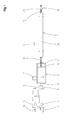
- Fig. 1 illustrated plant for the production of composite pipes has two extruders 1, 2. These are each driven by a variable-speed drive motor 3 or 3a, which - with respect to a conveying direction 4 of the entire system - upstream of the feed hoppers 5 of the extruder 1, 2 is provided.
- a forming machine 6 With reference to the conveying direction 4 downstream of the extruders 1, 2, a forming machine 6, a so-called corrugator, is arranged, to which in turn an aftercooling device 7 is arranged downstream.
- an extruder 1 On an extruder 1, which is arranged in alignment with the molding machine 6 and the aftercooling device 7, a transverse extrusion head 8, that is to say an extrusion tool, is mounted which projects into the molding machine 6.
- the other extruder 2 arranged laterally of this extruder 1 is connected to the transverse extrusion head 8 via an injection channel 9 which opens laterally into the transverse extrusion head 8.
- a composite pipe 10 is formed, which emerges in the conveying direction 4 from the molding machine 6 and is cooled in the aftercooling device 7. Behind This aftercooling device 7 can then be cut into pieces of suitable length.
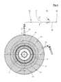
- the molding machine 6 is known in its construction and customary in practice. She is for example in the EP 0 563 575 B1 (corresponding U.S. Patent 5,320,797 ), to which reference is expressly made. It essentially has a machine table 11, on which half-molds 12, 12a are arranged. The half-molds 12, 12a are combined on the machine table 11 in the conveying direction 4 each to a mold pair 13 and from - related to the conveying direction 4 - upstream inlet end 14 to the downstream outlet end 15, again in the conveying direction 4 consecutively following mold pairs 13th close to each other.
- the drive of the half-molds 12, 12a, which are brought together in each case on mold sections 16 to mold pairs 13, takes place by means of a drive motor 17.
- the transport of the half-grooves 12, 12a and the mold pairs 13 on the machine table 11 is described in detail in FIG EP 0 764 516 B1 (corresponding US 5,693,347 ) and described, to which reference may be made.
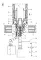
- the cross-spray head 8 has two concentric to a common central longitudinal axis 18 arranged melt channels, namely an inner melt channel 19 and an outer melt channel 20, which - related to the conveying direction 4 - downstream in an inner nozzle 21 and an outer nozzle 22 end.
- the inner melt channel 19 is connected to an injection channel 23 of the extruder 1 arranged in alignment with the molding machine 6, whereas the outer melt channel 20 is connected to the injection channel 9 of the other extruder 2.
- a calibration mandrel 25 is attached to this, which also extends concentrically to the axis 18.
- the spray head 8, so the extrusion tool is constructed in many parts.
- the inner melt channel 19 is delimited by an inner nozzle mandrel 26 and an inner nozzle jacket 27.
- the outer melt channel 20 is bounded by an outer nozzle mandrel 28 and an outer nozzle shell 29, wherein the description - with respect to the axis 18 - has taken place from the inside to the outside.
- the half-molds 12, 12a have annular shaped recesses 33, which are arranged at regular intervals one behind the other and which are each connected to partial vacuum channels 34. At the inlet of the half-molds 12, 12a in the molding section 16 reach the partial vacuum channels 34, not shown, in the EP 11 184 779.4 shown and described partial vacuum supply sources, so that the mold recesses 33 are subjected to partial vacuum.
- the spray head 8 supplied plastic melt flows through the outer melt channel 20 to the outer nozzle 22 and is extruded there to form an outer tube 35. Due to the partial vacuum and due to the support air supplied through the supporting air and venting channel 24, this outer tube 35 defines a shaped with annular wave crests 36 hose into the mold recesses 33. From the extruder 1 is through the spray channel 23 to the transverse Spray head 8 supplied plastic melt and flows through the inner melt channel 19 to the inner nozzle 21 and there emerges as an inner tube 37, which passes to the calibration mandrel 25.
- the half-molds 12, 12a are formed so that in each case at predetermined intervals within the endlessly produced composite pipe 10 connecting sleeves 39 are formed.
- a sleeve recess 40 is formed in a pair of half-molds 12, 12a, which thus has a substantially smooth, cylindrical wall 41.
- a transition surface 42 is formed between the wall 41 of the socket recess 40 and the leading in the conveying direction 4 mold cavity 33.
- the support air and vent channel 24 extends as well Fig. 2 can be removed - over a substantial part of the extension of the spray head 8 in the direction of the axis 18.
- a support air supply pipe 47 a It is connected via a support air line 48 to a compressed air source 49.
- a manually adjustable pressure regulator 50, a controllable solenoid valve 51 and a pressure gauge 52 are arranged. From the support air and vent channel 24 opens a constantly open to the atmosphere vent line 53 from.
- Fig. 5 shows a variant of the embodiment according to Fig. 4 ,
- an air distributor housing 54 is supported by means of a support plate 55 on the spray head 8.
- the air distributor housing 54 opens centrally the support air line 48 a.
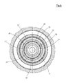
- Fig. 6 As Fig. 6 can be removed, are provided in the support air and venting channel 24 immediately before the exit space 57 between the outer nozzle 22 and inner nozzle 21 more in the present example by 120 ° staggered centering 58 to the outer nozzle mandrel 28 with the radially outboard parts relative to the inner nozzle shell 27 and the parts lying within this support and center.
- centering pieces 58 are to be dimensioned so that a sufficiently large free cross section in the supporting air and venting channel 24, 24 'remains.
- a modified cross-spray head 8 ' so a modified extrusion tool, shown, which is a so-called star distributor.
- This embodiment is used in particular in the production of pipes with a very large diameter, since in the conventional described embodiment of the spray heads whose weight is too large.
- Such a transverse extrusion head 8 ', as in the Fig. 7 and 8th is shown in the EP 2 116 352 B1 shown in detail and described, which may be referred to.
- the parts of the previous description the same parts are designated by the same reference numerals. Functionally identical but structurally different parts are designated by the same reference numerals with a prime, so that a detailed description is not necessary.
- the inner nozzle mandrel 26 ', the inner nozzle casing 27', the outer nozzle mandrel 28 'and the outer nozzle casing 29' are each composed of several parts.
- In the area in front of the outlet space 57 'of the supporting air and venting channel 24' is formed annular cylindrical concentric with the axis 18 and arranged.
- At least one support air feed tube 47 ' extends parallel to the axis through a portion of the crosshead 8', between the inner melt channel 19 'and the outer melt channel 20'.
- the support air supply tube 47 'and the vent line 53' terminate within the crosshead 8 'in an annular disk-shaped distributor channel 59, from which the support air and venting channel 24' opens.
- the minimum gap width a of the ring-cylindrical supporting air and venting channel 24 or 24 ' is to be sized sufficiently large. The following applies: a ⁇ 2.0 mm.
Abstract
Description
Die Erfindung betrifft eine Vorrichtung nach dem Oberbegriff des Anspruchs 1.The invention relates to a device according to the preamble of
Eine derartige Vorrichtung ist aus der
Aus der
Die Ausgestaltung mit einer ständigen Verbindung zur Atmosphäre hat sich grundsätzlich als vorteilhaft bei der Herstellung von großen Verbundrohren aus Polyolefinen, also Polyethylen und/oder Polypropylen bewiesen. Unter großen Verbundrohren werden hierbei Rohre mit Nennweiten ≥ DN 250 verstanden, wobei die Verbundrohre einfache Verbundrohre und Verbundrohre mit doppellagiger Verbindungsmuffe umfassen.The embodiment with a permanent connection to the atmosphere has proven to be advantageous in the production of large composite pipes of polyolefins, ie polyethylene and / or polypropylene. Large composite pipes are understood to mean pipes with nominal widths ≥ DN 250, the composite pipes comprising simple composite pipes and composite pipes with a double-layered connecting sleeve.
Es hat sich aber herausgestellt, dass dieses System noch verbesserungsbedürftig ist.However, it has turned out that this system is still in need of improvement.
Der Erfindung liegt daher die Aufgabe zu Grunde, eine Vorrichtung der eingangs vorausgesetzten Art dahingehend zu verbessern, dass die Steuerung des Luftdrucks im Raum zwischen Außen-Schlauch und Innen-Schlauch mit sehr einfachen Mitteln möglich ist.The invention is therefore based on the object to improve a device of the type initially assumed in that the control of the air pressure in the space between the outer tube and inner tube with very simple means is possible.
Diese Aufgabe wird erfindungsgemäß bei einer Vorrichtung nach dem Oberbegriff des Anspruches 1 durch die Merkmale in dessen Kennzeichnungsteil gelöst. Durch den groß dimensionierten bzw. dimensionierbaren Stützluft- und Entlüftungs-Kanal ist es möglich, einen entlang der Formstrecke sich verändernden Luftvolumenbedarf zwischen den Schläuchen auf einfache Weise zu kompensieren. Insbesondere bei großen Rohren kommt dies zum Tragen, da bei der Ausformung der Wellenberge größere Stützluft-Volumina erforderlich sind, während bei der Ausformung der Wellentäler, wo der Innen-Schlauch mit dem Außen-Schlauch verschweißt wird, wenig bzw. gar keine Stützluft erforderlich ist. Es kann nicht nur Stützluft zugeführt werden, sondern auch abgeführt werden.This object is achieved in a device according to the preamble of
Besonders vorteilhaft ist die erfindungsgemäße Ausgestaltung, wenn gemäß Anspruch 2 vorgesehen ist, auch doppellagige Verbindungs-Muffen auf der Vorrichtung herzustellen. Hier ist es durch den erfindungsgemäß groß dimensionierten bzw. dimensionierbaren Stützluft- und Entlüftungs-Kanal möglich, einerseits ein schnelles Entlüften an die Atmosphäre andererseits aber auch ein schnelles Zuführen von Atmosphärenluft bei einer pulsierenden Aufweitung des Innenschlauchs zur Verbindungs-Muffe zu erreichen. Dies erfolgt dadurch, dass neben der Stützluft je nach Bedarf mehr oder weniger Umgebungsluft nachströmen kann. Dies ist ein wichtiger Effekt bei leicht schwankenden Werten des Teilvakuums an den Halbkokillen. Dies gilt für die Herstellung der doppellagigen Verbindungs-Muffe, und zwar insbesondere im Hinblick auf die Anforderungen an denParticularly advantageous is the embodiment of the invention, if it is provided according to
Entlüftungsvorgang beim Übergang von der Muffenformung zurück auf die Herstellung des normal gewellten doppelwandigen Verbundrohres. Das System ist sehr stabil. Besondere Abdichtungsmaßnahmen im Bereich des Anfangs des Stützluft- und Entlüftungskanals sind nicht erforderlich, da das gesamte System nicht druckdicht sein muss und demzufolge auch nicht ist. Die Stützluft wird hierbei so bemessen, dass sie die Formgebung durch das Vakuumverfahren bereichsweise unterstützt, jedoch keinen dominierenden Einfluss auf die Formgebung, insbesondere während der Ausformung der doppellagigen Verbindungsmuffe, ausübt.Ventilation process at the transition from the socket forming back to the production of the normal corrugated double-walled composite pipe. The system is very stable. Special sealing measures in the area of the beginning of the supporting air and venting channel are not required because the entire system does not have to be pressure-tight and therefore is not. The support air is in this case dimensioned so that it partially supports the shaping by the vacuum method, but does not exert a dominating influence on the shaping, in particular during the shaping of the double-layered connecting sleeve.
Die Unteransprüche geben vorteilhafte Weiterbildungen wider.The dependent claims reflect advantageous developments.
Weitere Einzelheiten, Vorteile und Merkmale ergeben sich aus der nachfolgenden Beschreibung von Ausführungsbeispielen anhand der Zeichnung. Es zeigt:
- Fig. 1
- eine im Wesentlichen aus zwei Extrudern, einer Formmaschine und einer Nachkühlvorrichtung bestehende Anlage zur Herstellung von Verbundrohren mit Verbindungs-Muffen in Draufsicht in schematischer Darstellung,
- Fig. 2
- einen Spritzkopf und das Einlaufende der Formmaschine im Horizontalschnitt,
- Fig. 3
- einen Teilausschnitt aus
Fig. 2 in gegenüberFig. 2 vergrößertem Maßstab, - Fig. 4
- einen Querschnitt durch
Fig. 2 entsprechend der Schnittlinie IV-IV inFig. 2 , - Fig. 5
- eine gegenüber
Fig. 4 abgewandelte Querschnittsdarstellung, - Fig. 6
- einen Querschnitt durch Fig. III, entsprechend der Schnittlinie VI-VI in
Fig. 3 , - Fig. 7
- eine
Fig. 2 entsprechende Darstellung eines abgewandelten Spritzkopfes und - Fig. 8
- eine vergrößerte Teildarstellung aus
Fig. 7 .
- Fig. 1
- a system consisting essentially of two extruders, a molding machine and an aftercooler for the production of composite pipes with connecting sleeves in a plan view in schematic representation,
- Fig. 2
- a spray head and the inlet end of the molding machine in horizontal section,
- Fig. 3
- a partial section
Fig. 2 in oppositeFig. 2 enlarged scale, - Fig. 4
- a cross section through
Fig. 2 according to the section line IV-IV inFig. 2 . - Fig. 5
- one opposite
Fig. 4 modified cross-sectional representation, - Fig. 6
- a cross-section through Fig. III, corresponding to the section line VI-VI in
Fig. 3 . - Fig. 7
- a
Fig. 2 corresponding representation of a modified spray head and - Fig. 8
- an enlarged partial view
Fig. 7 ,
Die in
Bezogen auf die Förderrichtung 4 stromabwärts von den Extrudern 1, 2 ist eine Formmaschine 6, ein so genannter Korrugator, angeordnet, dem wiederum eine Nachkühlvorrichtung 7 nachgeordnet ist. An einem fluchtend mit der Formmaschine 6 und der Nachkühlvorrichtung 7 angeordneten Extruder 1 ist ein Quer-Spritzkopf 8 also ein Extrusionswerkzeug angebracht, der in die Formmaschine 6 hineinragt. Der andere, seitlich dieses Extruders 1 angeordnete Extruder 2 ist über einen seitlich in den Quer-Spritzkopf 8 einmündenden Spritzkanal 9 mit dem Quer-Spritzkopf 8 verbunden. Wie schematisch in
Die Formmaschine 6 ist in ihrem Aufbau bekannt und in der Praxis üblich. Sie ist beispielsweise in der
Der Quer-Spritzkopf 8 weist zwei konzentrisch zu einer gemeinsamen Mittel-Längs-Achse 18 angeordnete Schmelzekanäle, nämlich einen inneren Schmelzekanal 19 und einen äußeren Schmelzekanal 20, auf, die — bezogen auf die Förderrichtung 4 - stromabwärts in einer Innen-Düse 21 bzw. einer Außen-Düse 22 enden. Der innere Schmelzekanal 19 ist an einen Spritzkanal 23 des fluchtend mit der Formmaschine 6 angeordneten Extruders 1 angeschlossen, wogegen der äußere Schmelzekanal 20 an den Spritzkanal 9 des anderen Extruders 2 angeschlossen ist. Zwischen der Innen-Düse 21 und der Außen-Düse 22 mündet aus dem Spritzkopf 8 ein ringzylindrischer und zur Achse 18 konzentrischer Stützluft- und Entlüftungs-Kanal 24 aus.The
Am - bezogen auf die Förderrichtung 4 — stromabwärtigen Ende des Spritzkopfes 8 ist an diesem ein Kalibrierdorn 25 angebracht, der ebenfalls konzentrisch zur Achse 18 verläuft.At - with respect to the conveying direction 4 - downstream end of the
Der Spritzkopf 8, also das Extrusionswerkzeug, ist vielteilig aufgebaut. Der innere Schmelzekanal 19 wird von einem Innen-Düsendorn 26 und einem Innen-Düsenmantel 27 begrenzt. Der äußere Schmelzekanal 20 wird von einem Außen-Düsendorn 28 und einem Außen-Düsenmantel 29 begrenzt, wobei die Beschreibung — bezogen auf die Achse 18 — von innen nach außen erfolgt ist. Zwischen dem Innen-Düsenmantel 27 und dem Außen-Düsendorn 28 ist der Stützluft- und Entlüftungs-Kanal 24 ausgebildet und zwar als zur Achse 18 konzentrischer, ringzylindrischer Kanal 24.The
Auf dem Spritzkopf 8, also auf dessen Außen-Düsenmantel 29, ist — bezogen auf die Förderrichtung 4 - stromaufwärts der Außen-Düse 22 eine auswechselbar angebrachte, aus Halbschalen 30 gebildete, zylindrische Außenfläche 31 vorgesehen, zwischen denen und den Halbkokillen 12, 12a ein ringförmiger Dichtspalt 32 gebildet wird. Diese Ausgestaltung ist in der
Die Halbkokillen 12, 12a weisen ringförmige Formausnehmungen 33 auf, die in regelmäßigen Abständen hintereinander angeordnet sind und die jeweils an Teilvakuum-Kanäle 34 angeschlossen sind. Beim Einlauf der Halbkokillen 12, 12a in die Formstrecke 16 gelangen die Teilvakuum-Kanäle 34 an nicht dargestellte, in der
Die vom Extruder 2 durch den Spritzkanal 9 dem Spritzkopf 8 zugeführte Kunststoff-Schmelze strömt durch den äußeren Schmelzekanal 20 zur Außen-Düse 22 und wird dort unter Formung eines Außen-Schlauchs 35 extrudiert. Aufgrund des Teilvakuums und aufgrund von durch den Stützluft- und Entlüftungs-Kanal 24 zugeführter Stützluft legt sich dieser Außen-Schlauch 35 unter Formung eines mit ringförmigen Wellenbergen 36 ausgebildeten Schlauchs in die Formausnehmungen 33. Aus dem Extruder 1 wird durch den Spritzkanal 23 dem Quer-Spritzkopf 8 Kunststoff-Schmelze zugeführt und strömt durch den inneren Schmelzekanal 19 zur Innen-Düse 21 und tritt dort als Innen-Schlauch 37 aus, der auf den Kalibrier-Dorn 25 gelangt. Dieser erweitert sich von der Innen-Düse 21 in Förderrichtung 4 leicht nach außen, bis der Innen-Schlauch 37 gegen die Wellentäler 38 des Außen-Schlauchs 35 gelangt und hier mit diesem verschweißt wird. Der Innen-Schlauch 37 und der Außen-Schlauch 35 bilden nach Abkühlung unter Erstarrung das Verbundrohr 10.The from the
Wie insbesondere aus den
Der Stützluft- und Entlüftungs-Kanal 24 erstreckt sich —wie
Wie
In den
Der Innen-Düsendorn 26', der Innen-Düsenmantel 27', der Außen-Düsendorn 28' und der Außen-Düsenmantel 29' sind jeweils aus mehreren Teilen zusammengesetzt. Im Bereich vor dem Austritts-Raum 57' ist der Stützluft- und Entlüftungs-Kanal 24' ringzylindrisch konzentrisch zur Achse 18 ausgebildet und angeordnet.The inner nozzle mandrel 26 ', the inner nozzle casing 27', the outer nozzle mandrel 28 'and the outer nozzle casing 29' are each composed of several parts. In the area in front of the outlet space 57 'of the supporting air and venting channel 24' is formed annular cylindrical concentric with the
Mindestens ein Stützluft-Zuführrohr 47' verläuft parallel zur Achse durch einen Teil des Quer-Spritzkopfes 8', und zwar zwischen dem inneren Schmelzekanal 19' und dem äußeren Schmelzekanal 20'. Entsprechend angeordnet ist mindestens eine Entlüftungs-Leitung 53'. Das Stützluft-Zuführrohr 47' und die Entlüftungs-Leitung 53' enden innerhalb des Quer-Spritzkopfes 8' in einem ringscheibenförmigen Verteiler-Kanal 59, aus dem der Stützluft- und Entlüftungs-Kanal 24' ausmündet.At least one support air feed tube 47 'extends parallel to the axis through a portion of the crosshead 8', between the inner melt channel 19 'and the outer melt channel 20'. Correspondingly arranged is at least one venting line 53 '. The support air supply tube 47 'and the vent line 53' terminate within the crosshead 8 'in an annular disk-shaped
Die Mindest-Spaltweite a des ringzylindrischen Stützluft- und EntlüftungsKanals 24 bzw. 24' ist ausreichend groß zu bemessen. Es gilt: a ≥ 2,0 mm.The minimum gap width a of the ring-cylindrical supporting air and venting
Während der Produktion des Verbundrohres 10 wird Teilvakuum auf die Teilvakuum-Kanäle 34 aufgebracht, also sowohl auf die Formausnehmungen 33 als auch auf die Muffen-Ausnehmung 40. Während der Herstellung des normalen Verbundrohres 10 mit Wellenbergen 36 wird das Magnetventil 51 geöffnet, sodass von der Druckluftquelle 49 Druckluft mit einem am Druckregler 50 eingestellten Druck über den Stützluft- und Entlüftungs-Kanal 24 bzw. 24' in den Raum 57 zwischen dem Innen-Schlauch 37 und dem Außen-Schlauch 35 eingegeben wird. Da der Kanal 24 bzw. 24' ständig zur Atmosphäre geöffnet ist, stellt sich ein in der Praxis ermittelbarer Stützluft-Druck ein, der deutlich niedriger als der Vordruck in der Stützluft-Leitung 48 ist. Durch das Teilvakuum in den Formausnehmungen 33 und die leichte Unterstützung durch die Stützluft wird der Außen-Schlauch 35 an die Wand der Formausnehmung 33 angelegt und somit der Außen-schlauch ausgeformt. Die jeweils bei der Ausformung eines Wellenberges 36 bzw. eines Wellentales 38 im Außen-Schlauch 35 schwankenden Luftvolumina der Stützluft werden über den Stützluft- und Entlüftungs-Kanal 24 bzw. 24' kompensiert bzw. ausgepuffert. Drucksteuerungseinrichtungen für die Stützluft sind also nicht erforderlich. Die Stützluftzufuhr bleibt aufrecht erhalten, bis die Übergangs-Fläche 42 der Muffen-Ausnehmung 40 die Innen-Düse 21 erreicht, wie es in den
Der Druckabfall, also der Druckausgleich, von dem leichten Überdruck auf Atmosphärendruck beim Schließen des Magnetventils 51 erfolgt kurzzeitig, d.h. nahezu angenähert schlagartig; das Entlüften des Raums 57 erstreckt sich über den gesamten Zeitraum der Aufweitung des Innen-Schlauches 37 zur Verbindungs-Muffe 39.The pressure drop, so the pressure equalization, from the slight overpressure to atmospheric pressure when closing the
Claims (9)
dass der Stützluft-Kanal als ständig zur Atmosphäre offener, zumindest benachbart zum Bereich zwischen Innen-Düse (21) und Außen-Düse (22) ringzylindrischer und zur Mittel-Längs-Achse (18) konzentrischer Stützluft- und Entlüftungs-Kanal (24, 24') ausgebildet ist.
in that the support air channel is in the form of a constantly open air-venting channel (24, 24) at least adjacent to the area between the inner nozzle (21) and the outer nozzle (22) and cylindrical to the central longitudinal axis (18). 24 ') is formed.
dass zwischen Innen-Düse (21) und Kalibrierdorn (25) mindestens ein zusätzlicher Gas-Kanal (60) aus dem Spritzkopf (8) ausmündet,
dass mindestens ein Paar Halbkokillen (12, 12a) mit einer Muffen-Ausnehmung (40) versehen ist, und
dass die Muffen-Ausnehmung (40) durch eine in Förderrichtung (4) voreilende Übergangs-Fläche (42) begrenzt ist.Device according to claim 1, characterized in that
that between inner nozzle (21) and calibration mandrel (25) at least one additional gas channel (60) opens out of the spray head (8),
that at least one pair of half-molds (12, 12a) is provided with a socket recess (40), and
in that the sleeve recess (40) is delimited by a transition surface (42) leading in the conveying direction (4).
dass der Stützluft- und Entlüftungs-Kanal (24) sich über einen wesentlichen Teil der Länge des Spritzkopfes (8) erstreckt.Device according to Claim 1 or 2, characterized
in that the support air and vent channel (24) extends over a substantial part of the length of the spray head (8).
dass der Stützluft- und Entlüftungs-Kanal (24, 24') eine Spaltweite a aufweist, für die gilt: a ≥ 2,0 mm.Device according to one of claims 1 to 3, characterized
in that the supporting air and venting channel (24, 24 ') has a gap width a for which the following applies: a ≥ 2.0 mm.
dass der Stützluft- und Entlüftungs-Kanal (24, 24') an mindestens ein Stützluft-Zuführrohr (47, 47') angeschlossen ist.Device according to one of claims 1 to 4, characterized
in that the supporting air and venting channel (24, 24 ') is connected to at least one supporting air supply pipe (47, 47').
dass der Stützluft- und Entlüftungs-Kanal (24, 24') an mindestens eine Stützluft-Leitung (48) angeschlossen ist, die an eine Druckluftquelle (49) angeschlossen ist.Device according to one of claims 1 to 5, characterized
in that the support air and vent channel (24, 24 ') is connected to at least one support air line (48) which is connected to a compressed air source (49).
dass dem Stützluft- und Entlüftungs-Kanal (24, 24') ein Druckregler (50), ein Magnetventil (51) und ein Druck-Messgerät (52) vorgeordnet sind.Device according to one of claims 1 to 6, characterized
in that a pressure regulator (50), a solenoid valve (51) and a pressure measuring device (52) are arranged in front of the supporting air and venting channel (24, 24 ').
dass aus dem Stützluft- und Entlüftungs-Kanal (24, 24') eine ständig zur Atmosphäre offene Entlüftungs-Leitung (53, 53') ausmündet.Device according to one of claims 1 to 7, characterized
in that a venting line (53, 53 ') which is constantly open to the atmosphere opens out of the support air and venting channel (24, 24').
dass dem Stützluft- und Entlüftungs-Kanal (24) ein Luft-Verteiler-Gehäuse (54) vorgeordnet ist, in das eine Stützluft-Leitung (48) einmündet und aus dem eine Entlüftungs-Leitung (53) ausmündet und mit mehreren Stützluft- und Entlüftungs-Leitungen (56) mit dem Stützluft-und Entlüftungs-Kanal (24) verbunden ist.Device according to one of claims 1 to 7, characterized
that the support air and vent channel (24) upstream of an air distributor housing (54) into which a support air line (48) opens and from which opens a vent line (53) and with several Stützluft- and Vent lines (56) to the support air and vent channel (24) is connected.
Priority Applications (5)
| Application Number | Priority Date | Filing Date | Title |
|---|---|---|---|
| PL11187934T PL2589481T3 (en) | 2011-11-04 | 2011-11-04 | Device for continuously manufacturing a composite pipe with connection sleeve |
| EP11187934.2A EP2589481B1 (en) | 2011-11-04 | 2011-11-04 | Device for continuously manufacturing a composite pipe with connection sleeve |
| US13/659,166 US8794948B2 (en) | 2011-11-04 | 2012-10-24 | Apparatus for the continuous production of a twin wall pipe with an integral socket |
| CA2794366A CA2794366C (en) | 2011-11-04 | 2012-10-29 | Apparatus for the continuous production of a twin wall pipe with an integral socket |
| BR102012028016-7A BR102012028016B1 (en) | 2011-11-04 | 2012-10-31 | device for the continuous production of a double-walled tube |
Applications Claiming Priority (1)
| Application Number | Priority Date | Filing Date | Title |
|---|---|---|---|
| EP11187934.2A EP2589481B1 (en) | 2011-11-04 | 2011-11-04 | Device for continuously manufacturing a composite pipe with connection sleeve |
Publications (2)
| Publication Number | Publication Date |
|---|---|
| EP2589481A1 true EP2589481A1 (en) | 2013-05-08 |
| EP2589481B1 EP2589481B1 (en) | 2016-01-20 |
Family
ID=45509204
Family Applications (1)
| Application Number | Title | Priority Date | Filing Date |
|---|---|---|---|
| EP11187934.2A Active EP2589481B1 (en) | 2011-11-04 | 2011-11-04 | Device for continuously manufacturing a composite pipe with connection sleeve |
Country Status (5)
| Country | Link |
|---|---|
| US (1) | US8794948B2 (en) |
| EP (1) | EP2589481B1 (en) |
| BR (1) | BR102012028016B1 (en) |
| CA (1) | CA2794366C (en) |
| PL (1) | PL2589481T3 (en) |
Cited By (9)
| Publication number | Priority date | Publication date | Assignee | Title |
|---|---|---|---|---|
| CN106003656A (en) * | 2016-08-05 | 2016-10-12 | 张家港市金达利模塑有限公司 | Double-wall corrugated pipe extrusion die |
| CN106042321A (en) * | 2016-08-05 | 2016-10-26 | 张家港市金达利模塑有限公司 | Double-wall bellows extrusion mold interlayer airtight independent airway |
| WO2017019374A1 (en) * | 2014-07-29 | 2017-02-02 | Cc3D Llc | Method and apparatus for additive mechanical growth of tubular structures |
| DE102015219221A1 (en) | 2015-10-06 | 2017-04-06 | Ralph Peter Hegler | Spray head for a device for producing a composite pipe |
| US10335999B2 (en) | 2016-04-15 | 2019-07-02 | Cc3D Llc | Head and system for continuously manufacturing composite hollow structure |
| US10345068B2 (en) | 2017-02-13 | 2019-07-09 | Cc3D Llc | Composite sporting equipment |
| US10766594B2 (en) | 2016-11-03 | 2020-09-08 | Continuous Composites Inc. | Composite vehicle body |
| US10870233B2 (en) | 2016-11-04 | 2020-12-22 | Continuous Composites Inc. | Additive manufacturing system having feed-tensioner |
| US11235522B2 (en) | 2018-10-04 | 2022-02-01 | Continuous Composites Inc. | System for additively manufacturing composite structures |
Families Citing this family (39)
| Publication number | Priority date | Publication date | Assignee | Title |
|---|---|---|---|---|
| US9511543B2 (en) | 2012-08-29 | 2016-12-06 | Cc3D Llc | Method and apparatus for continuous composite three-dimensional printing |
| DE102012022409B3 (en) * | 2012-11-15 | 2013-05-29 | Heinz Gross | Hose head for use with trifunctional component for discharging molten tube for manufacturing of capillaries, tubes or pipes, has sleeve-shaped housing, in which melt is fed, where housing surrounds core |
| FR3044867B1 (en) | 2015-12-09 | 2018-01-26 | S.P.C.M. Sa | TREATMENT OF SEEDS BY HYDROGONFLABLE POLYMER |
| US10105910B2 (en) | 2016-04-15 | 2018-10-23 | Cc3D Llc | Method for continuously manufacturing composite hollow structure |
| US20180065317A1 (en) | 2016-09-06 | 2018-03-08 | Cc3D Llc | Additive manufacturing system having in-situ fiber splicing |
| US10625467B2 (en) | 2016-09-06 | 2020-04-21 | Continuous Composites Inc. | Additive manufacturing system having adjustable curing |
| US10759113B2 (en) | 2016-09-06 | 2020-09-01 | Continuous Composites Inc. | Additive manufacturing system having trailing cure mechanism |
| US10543640B2 (en) | 2016-09-06 | 2020-01-28 | Continuous Composites Inc. | Additive manufacturing system having in-head fiber teasing |
| US10908576B2 (en) | 2016-09-06 | 2021-02-02 | Continuous Composites Inc. | Systems and methods for controlling additive manufacturing |
| US20210094230A9 (en) | 2016-11-04 | 2021-04-01 | Continuous Composites Inc. | System for additive manufacturing |
| US10040240B1 (en) | 2017-01-24 | 2018-08-07 | Cc3D Llc | Additive manufacturing system having fiber-cutting mechanism |
| US10857726B2 (en) | 2017-01-24 | 2020-12-08 | Continuous Composites Inc. | Additive manufacturing system implementing anchor curing |
| US10798783B2 (en) | 2017-02-15 | 2020-10-06 | Continuous Composites Inc. | Additively manufactured composite heater |
| US10814569B2 (en) | 2017-06-29 | 2020-10-27 | Continuous Composites Inc. | Method and material for additive manufacturing |
| US20190001563A1 (en) | 2017-06-29 | 2019-01-03 | Cc3D Llc | Print head for additive manufacturing system |
| US10319499B1 (en) | 2017-11-30 | 2019-06-11 | Cc3D Llc | System and method for additively manufacturing composite wiring harness |
| US10131088B1 (en) | 2017-12-19 | 2018-11-20 | Cc3D Llc | Additive manufacturing method for discharging interlocking continuous reinforcement |
| US10919222B2 (en) | 2017-12-29 | 2021-02-16 | Continuous Composites Inc. | System and method for additively manufacturing functional elements into existing components |
| US10759114B2 (en) | 2017-12-29 | 2020-09-01 | Continuous Composites Inc. | System and print head for continuously manufacturing composite structure |
| US10081129B1 (en) | 2017-12-29 | 2018-09-25 | Cc3D Llc | Additive manufacturing system implementing hardener pre-impregnation |
| US10857729B2 (en) | 2017-12-29 | 2020-12-08 | Continuous Composites Inc. | System and method for additively manufacturing functional elements into existing components |
| US11167495B2 (en) | 2017-12-29 | 2021-11-09 | Continuous Composites Inc. | System and method for additively manufacturing functional elements into existing components |
| US11161300B2 (en) | 2018-04-11 | 2021-11-02 | Continuous Composites Inc. | System and print head for additive manufacturing system |
| US11110654B2 (en) | 2018-04-12 | 2021-09-07 | Continuous Composites Inc. | System and print head for continuously manufacturing composite structure |
| US11110656B2 (en) | 2018-04-12 | 2021-09-07 | Continuous Composites Inc. | System for continuously manufacturing composite structure |
| US11052603B2 (en) | 2018-06-07 | 2021-07-06 | Continuous Composites Inc. | Additive manufacturing system having stowable cutting mechanism |
| US20200086563A1 (en) | 2018-09-13 | 2020-03-19 | Cc3D Llc | System and head for continuously manufacturing composite structure |
| US11325304B2 (en) | 2018-10-26 | 2022-05-10 | Continuous Composites Inc. | System and method for additive manufacturing |
| US11358331B2 (en) | 2018-11-19 | 2022-06-14 | Continuous Composites Inc. | System and head for continuously manufacturing composite structure |
| US11420390B2 (en) | 2018-11-19 | 2022-08-23 | Continuous Composites Inc. | System for additively manufacturing composite structure |
| US20200238603A1 (en) | 2019-01-25 | 2020-07-30 | Continuous Composites Inc. | System for additively manufacturing composite structure |
| US20200376758A1 (en) | 2019-05-28 | 2020-12-03 | Continuous Composites Inc. | System for additively manufacturing composite structure |
| US11840022B2 (en) | 2019-12-30 | 2023-12-12 | Continuous Composites Inc. | System and method for additive manufacturing |
| US11904534B2 (en) | 2020-02-25 | 2024-02-20 | Continuous Composites Inc. | Additive manufacturing system |
| US11926100B2 (en) | 2020-06-23 | 2024-03-12 | Continuous Composites Inc. | Systems and methods for controlling additive manufacturing |
| US11465348B2 (en) | 2020-09-11 | 2022-10-11 | Continuous Composites Inc. | Print head for additive manufacturing system |
| US11926099B2 (en) | 2021-04-27 | 2024-03-12 | Continuous Composites Inc. | Additive manufacturing system |
| CN113459463B (en) * | 2021-07-09 | 2023-03-31 | 泰州长力树脂管有限公司 | PVC pipe production equipment and process |
| CN115041685A (en) * | 2022-05-25 | 2022-09-13 | 邯郸新兴特种管材有限公司 | Method for forming molybdenum tube |
Citations (7)
| Publication number | Priority date | Publication date | Assignee | Title |
|---|---|---|---|---|
| US5320797A (en) | 1992-03-31 | 1994-06-14 | Wilhelm Hegler | Method and apparatus for the continuous manufacture of a compound pipe with a pipe socket |
| US5693347A (en) | 1995-09-22 | 1997-12-02 | Hegler Ralph Peter | Apparatus for the manufacture of pipes of thermoplastic plastics having transverse profile features |
| EP0995579A2 (en) * | 1998-10-21 | 2000-04-26 | Hegler, Ralph-Peter, Dr.-Ing. | Method for continuous production of a composite pipe with socket and apparatus for carrying out the method |
| WO2005009720A1 (en) * | 2003-07-31 | 2005-02-03 | Manfred Arno Alfred Lupke | Device for manufacturing a double-walled thermoplastic pipe with a connecting sleeve |
| EP1612030A1 (en) * | 2004-07-03 | 2006-01-04 | Ralph-Peter Dr.-Ing. Hegler | Method for continuous manufacturing of a double walled corrugated pipe with a socket, the double walled corrugated pipe and the apparatus for performing the method |
| EP2103412A1 (en) | 2008-03-18 | 2009-09-23 | Ralph-Peter Dr.-Ing. Hegler | Method for continuous manufacture of a connecting rod with rod fitting and device for executing the method |
| EP2116352B1 (en) | 2008-05-09 | 2010-06-09 | Ralph-Peter Dr.-Ing. Hegler | Extrusion tool for a device for producing plastic connecting rods with grooves |
Family Cites Families (4)
| Publication number | Priority date | Publication date | Assignee | Title |
|---|---|---|---|---|
| AT325299B (en) * | 1967-02-27 | 1975-10-10 | Hegler Wilhelm | DEVICE FOR MANUFACTURING TUBES FROM THERMOPLASTIC PLASTIC |
| US5124109A (en) * | 1984-07-18 | 1992-06-23 | Contech Construction Products Inc. | Method for producing a double wall pipe |
| US6787092B2 (en) * | 2001-04-06 | 2004-09-07 | Harry Chan | Pipe extrusion die for multi-layer pipe |
| DE102010043786B4 (en) | 2010-11-11 | 2013-07-18 | Ralph Peter Hegler | Device for producing pipes made of thermoplastic material |
-
2011
- 2011-11-04 EP EP11187934.2A patent/EP2589481B1/en active Active
- 2011-11-04 PL PL11187934T patent/PL2589481T3/en unknown
-
2012
- 2012-10-24 US US13/659,166 patent/US8794948B2/en not_active Expired - Fee Related
- 2012-10-29 CA CA2794366A patent/CA2794366C/en active Active
- 2012-10-31 BR BR102012028016-7A patent/BR102012028016B1/en active IP Right Grant
Patent Citations (11)
| Publication number | Priority date | Publication date | Assignee | Title |
|---|---|---|---|---|
| US5320797A (en) | 1992-03-31 | 1994-06-14 | Wilhelm Hegler | Method and apparatus for the continuous manufacture of a compound pipe with a pipe socket |
| EP0563575B1 (en) | 1992-03-31 | 1995-09-27 | Wilhelm Hegler | Method and apparatus for continuous production of a composite pipe with sleeve |
| US5320797B1 (en) | 1992-03-31 | 1997-04-08 | Wilhelm Hegler | Method and apparatus for the continuous manufacture of a compound pipe with a pipe socket |
| US5693347A (en) | 1995-09-22 | 1997-12-02 | Hegler Ralph Peter | Apparatus for the manufacture of pipes of thermoplastic plastics having transverse profile features |
| EP0764516B1 (en) | 1995-09-22 | 2001-03-07 | Ralph-Peter Dr.-Ing. Hegler | Apparatus for producing transversely grooved thermoplastic tubes |
| EP0995579A2 (en) * | 1998-10-21 | 2000-04-26 | Hegler, Ralph-Peter, Dr.-Ing. | Method for continuous production of a composite pipe with socket and apparatus for carrying out the method |
| WO2005009720A1 (en) * | 2003-07-31 | 2005-02-03 | Manfred Arno Alfred Lupke | Device for manufacturing a double-walled thermoplastic pipe with a connecting sleeve |
| EP1612030A1 (en) * | 2004-07-03 | 2006-01-04 | Ralph-Peter Dr.-Ing. Hegler | Method for continuous manufacturing of a double walled corrugated pipe with a socket, the double walled corrugated pipe and the apparatus for performing the method |
| EP2103412A1 (en) | 2008-03-18 | 2009-09-23 | Ralph-Peter Dr.-Ing. Hegler | Method for continuous manufacture of a connecting rod with rod fitting and device for executing the method |
| US20090236032A1 (en) | 2008-03-18 | 2009-09-24 | Ralph Peter Hegler | Method of continuously manufacturing a compound pipe comprising a pipe socket and apparatus for implementing the method |
| EP2116352B1 (en) | 2008-05-09 | 2010-06-09 | Ralph-Peter Dr.-Ing. Hegler | Extrusion tool for a device for producing plastic connecting rods with grooves |
Cited By (15)
| Publication number | Priority date | Publication date | Assignee | Title |
|---|---|---|---|---|
| RU2671337C1 (en) * | 2014-07-29 | 2018-10-30 | СиСи3Ди ЭлЭлСи | Method and device for additive mechanical extension of tubular structures |
| WO2017019374A1 (en) * | 2014-07-29 | 2017-02-02 | Cc3D Llc | Method and apparatus for additive mechanical growth of tubular structures |
| US9808991B2 (en) | 2014-07-29 | 2017-11-07 | Cc3D Llc. | Method and apparatus for additive mechanical growth of tubular structures |
| US10583596B2 (en) | 2015-10-06 | 2020-03-10 | Ralph Peter Hegler | Injection head for an apparatus for the production of a twin-wall pipe |
| DE102015219221A1 (en) | 2015-10-06 | 2017-04-06 | Ralph Peter Hegler | Spray head for a device for producing a composite pipe |
| EP3153296A1 (en) | 2015-10-06 | 2017-04-12 | Ralph Peter Hegler | Extrusion head for a device for producing a composite pipe |
| US10335999B2 (en) | 2016-04-15 | 2019-07-02 | Cc3D Llc | Head and system for continuously manufacturing composite hollow structure |
| CN106042321B (en) * | 2016-08-05 | 2018-06-29 | 张家港市金达利模塑有限公司 | The closed separated air flue of double-wall corrugated pipe extrusion die interbedded gas |
| CN106003656B (en) * | 2016-08-05 | 2018-03-06 | 张家港市金达利模塑有限公司 | Double-wall corrugated pipe extrusion die |
| CN106003656A (en) * | 2016-08-05 | 2016-10-12 | 张家港市金达利模塑有限公司 | Double-wall corrugated pipe extrusion die |
| CN106042321A (en) * | 2016-08-05 | 2016-10-26 | 张家港市金达利模塑有限公司 | Double-wall bellows extrusion mold interlayer airtight independent airway |
| US10766594B2 (en) | 2016-11-03 | 2020-09-08 | Continuous Composites Inc. | Composite vehicle body |
| US10870233B2 (en) | 2016-11-04 | 2020-12-22 | Continuous Composites Inc. | Additive manufacturing system having feed-tensioner |
| US10345068B2 (en) | 2017-02-13 | 2019-07-09 | Cc3D Llc | Composite sporting equipment |
| US11235522B2 (en) | 2018-10-04 | 2022-02-01 | Continuous Composites Inc. | System for additively manufacturing composite structures |
Also Published As
| Publication number | Publication date |
|---|---|
| CA2794366C (en) | 2019-06-04 |
| US20130115324A1 (en) | 2013-05-09 |
| BR102012028016A2 (en) | 2014-10-29 |
| US8794948B2 (en) | 2014-08-05 |
| CA2794366A1 (en) | 2013-05-04 |
| EP2589481B1 (en) | 2016-01-20 |
| BR102012028016A8 (en) | 2018-05-15 |
| PL2589481T3 (en) | 2016-06-30 |
| BR102012028016B1 (en) | 2021-01-05 |
Similar Documents
| Publication | Publication Date | Title |
|---|---|---|
| EP2589481B1 (en) | Device for continuously manufacturing a composite pipe with connection sleeve | |
| EP0995579B1 (en) | Method for continuous production of a composite pipe with socket and apparatus for carrying out the method | |
| EP1612030B1 (en) | Method for continuous manufacturing of a double walled corrugated pipe with a socket, the double walled corrugated pipe and the apparatus for performing the method | |
| DE19724113A1 (en) | Composite pipe with molded pipe sleeve and method for its production | |
| DE2403618A1 (en) | DEVICE FOR PRODUCING A DOUBLE-WALLED PLASTIC PIPE | |
| EP2452803B1 (en) | Device for producing corrugated thermoplastic tubes | |
| EP2065159A1 (en) | Device for continuously manufacturing a connecting pipe with pipe sleeve | |
| EP1916089B1 (en) | Device for extruding hollow rods | |
| EP2125329B1 (en) | Method and device for the continuous manufacture of a plastic composite pipe having a connecting sleeve | |
| DE102009027437B4 (en) | Apparatus and method for cooling plastic profiles | |
| EP1914060A2 (en) | Device for extruding hollow rods | |
| EP3153296B1 (en) | Extrusion head for a device for producing a composite pipe | |
| DE19843341A1 (en) | Device for the production of plastic pipes | |
| EP1923199B1 (en) | Device for extruding hollow rods | |
| EP2425958B1 (en) | Apparatus for continuouly producing a compound pipe comprising a pipe socket | |
| EP2252449B1 (en) | Method and device for the continuous production of a composite pipe having a pipe bell and composite pipe | |
| WO2010029143A2 (en) | Device and method for cooling plastic profiles | |
| EP2436504B1 (en) | Method for continuous manufacture of a connecting tube with rod fitting, connecting tube with rod fitting and device for executing the method and manufacturing the connecting tube | |
| DE202008018223U1 (en) | Apparatus for the continuous production of a composite pipe with pipe socket | |
| DE3426680C2 (en) | ||
| DE202004019566U1 (en) | Transfer section between die and sizing ring for extrusion of hollow sections involves a vacuum chamber to draw material against outer guides | |
| WO2010029142A2 (en) | Device and method for cooling plastic profiles | |
| DE102006061059A1 (en) | Method and device for producing a plastic molding |
Legal Events
| Date | Code | Title | Description |
|---|---|---|---|
| PUAI | Public reference made under article 153(3) epc to a published international application that has entered the european phase |
Free format text: ORIGINAL CODE: 0009012 |
|
| AK | Designated contracting states |
Kind code of ref document: A1 Designated state(s): AL AT BE BG CH CY CZ DE DK EE ES FI FR GB GR HR HU IE IS IT LI LT LU LV MC MK MT NL NO PL PT RO RS SE SI SK SM TR |
|
| AX | Request for extension of the european patent |
Extension state: BA ME |
|
| 17P | Request for examination filed |
Effective date: 20131104 |
|
| RBV | Designated contracting states (corrected) |
Designated state(s): AL AT BE BG CH CY CZ DE DK EE ES FI FR GB GR HR HU IE IS IT LI LT LU LV MC MK MT NL NO PL PT RO RS SE SI SK SM TR |
|
| GRAP | Despatch of communication of intention to grant a patent |
Free format text: ORIGINAL CODE: EPIDOSNIGR1 |
|
| RIC1 | Information provided on ipc code assigned before grant |
Ipc: B29C 47/12 20060101AFI20150918BHEP Ipc: B29C 47/92 20060101ALI20150918BHEP Ipc: B29C 47/06 20060101ALN20150918BHEP Ipc: B29C 49/00 20060101ALN20150918BHEP |
|
| INTG | Intention to grant announced |
Effective date: 20151009 |
|
| GRAS | Grant fee paid |
Free format text: ORIGINAL CODE: EPIDOSNIGR3 |
|
| GRAA | (expected) grant |
Free format text: ORIGINAL CODE: 0009210 |
|
| AK | Designated contracting states |
Kind code of ref document: B1 Designated state(s): AL AT BE BG CH CY CZ DE DK EE ES FI FR GB GR HR HU IE IS IT LI LT LU LV MC MK MT NL NO PL PT RO RS SE SI SK SM TR |
|
| REG | Reference to a national code |
Ref country code: GB Ref legal event code: FG4D Free format text: NOT ENGLISH |
|
| REG | Reference to a national code |
Ref country code: CH Ref legal event code: EP |
|
| REG | Reference to a national code |
Ref country code: IE Ref legal event code: FG4D Free format text: LANGUAGE OF EP DOCUMENT: GERMAN |
|
| REG | Reference to a national code |
Ref country code: AT Ref legal event code: REF Ref document number: 771488 Country of ref document: AT Kind code of ref document: T Effective date: 20160215 |
|
| REG | Reference to a national code |
Ref country code: DE Ref legal event code: R096 Ref document number: 502011008699 Country of ref document: DE |
|
| REG | Reference to a national code |
Ref country code: LT Ref legal event code: MG4D Ref country code: NL Ref legal event code: MP Effective date: 20160120 |
|
| PG25 | Lapsed in a contracting state [announced via postgrant information from national office to epo] |
Ref country code: NL Free format text: LAPSE BECAUSE OF FAILURE TO SUBMIT A TRANSLATION OF THE DESCRIPTION OR TO PAY THE FEE WITHIN THE PRESCRIBED TIME-LIMIT Effective date: 20160120 |
|
| PG25 | Lapsed in a contracting state [announced via postgrant information from national office to epo] |
Ref country code: GR Free format text: LAPSE BECAUSE OF FAILURE TO SUBMIT A TRANSLATION OF THE DESCRIPTION OR TO PAY THE FEE WITHIN THE PRESCRIBED TIME-LIMIT Effective date: 20160421 Ref country code: NO Free format text: LAPSE BECAUSE OF FAILURE TO SUBMIT A TRANSLATION OF THE DESCRIPTION OR TO PAY THE FEE WITHIN THE PRESCRIBED TIME-LIMIT Effective date: 20160420 Ref country code: ES Free format text: LAPSE BECAUSE OF FAILURE TO SUBMIT A TRANSLATION OF THE DESCRIPTION OR TO PAY THE FEE WITHIN THE PRESCRIBED TIME-LIMIT Effective date: 20160120 Ref country code: IT Free format text: LAPSE BECAUSE OF FAILURE TO SUBMIT A TRANSLATION OF THE DESCRIPTION OR TO PAY THE FEE WITHIN THE PRESCRIBED TIME-LIMIT Effective date: 20160120 Ref country code: HR Free format text: LAPSE BECAUSE OF FAILURE TO SUBMIT A TRANSLATION OF THE DESCRIPTION OR TO PAY THE FEE WITHIN THE PRESCRIBED TIME-LIMIT Effective date: 20160120 Ref country code: FI Free format text: LAPSE BECAUSE OF FAILURE TO SUBMIT A TRANSLATION OF THE DESCRIPTION OR TO PAY THE FEE WITHIN THE PRESCRIBED TIME-LIMIT Effective date: 20160120 |
|
| PG25 | Lapsed in a contracting state [announced via postgrant information from national office to epo] |
Ref country code: PT Free format text: LAPSE BECAUSE OF FAILURE TO SUBMIT A TRANSLATION OF THE DESCRIPTION OR TO PAY THE FEE WITHIN THE PRESCRIBED TIME-LIMIT Effective date: 20160520 Ref country code: SE Free format text: LAPSE BECAUSE OF FAILURE TO SUBMIT A TRANSLATION OF THE DESCRIPTION OR TO PAY THE FEE WITHIN THE PRESCRIBED TIME-LIMIT Effective date: 20160120 Ref country code: LT Free format text: LAPSE BECAUSE OF FAILURE TO SUBMIT A TRANSLATION OF THE DESCRIPTION OR TO PAY THE FEE WITHIN THE PRESCRIBED TIME-LIMIT Effective date: 20160120 Ref country code: IS Free format text: LAPSE BECAUSE OF FAILURE TO SUBMIT A TRANSLATION OF THE DESCRIPTION OR TO PAY THE FEE WITHIN THE PRESCRIBED TIME-LIMIT Effective date: 20160520 Ref country code: RS Free format text: LAPSE BECAUSE OF FAILURE TO SUBMIT A TRANSLATION OF THE DESCRIPTION OR TO PAY THE FEE WITHIN THE PRESCRIBED TIME-LIMIT Effective date: 20160120 Ref country code: LV Free format text: LAPSE BECAUSE OF FAILURE TO SUBMIT A TRANSLATION OF THE DESCRIPTION OR TO PAY THE FEE WITHIN THE PRESCRIBED TIME-LIMIT Effective date: 20160120 |
|
| REG | Reference to a national code |
Ref country code: DE Ref legal event code: R097 Ref document number: 502011008699 Country of ref document: DE |
|
| PG25 | Lapsed in a contracting state [announced via postgrant information from national office to epo] |
Ref country code: DK Free format text: LAPSE BECAUSE OF FAILURE TO SUBMIT A TRANSLATION OF THE DESCRIPTION OR TO PAY THE FEE WITHIN THE PRESCRIBED TIME-LIMIT Effective date: 20160120 Ref country code: EE Free format text: LAPSE BECAUSE OF FAILURE TO SUBMIT A TRANSLATION OF THE DESCRIPTION OR TO PAY THE FEE WITHIN THE PRESCRIBED TIME-LIMIT Effective date: 20160120 |
|
| REG | Reference to a national code |
Ref country code: FR Ref legal event code: PLFP Year of fee payment: 6 |
|
| PLBE | No opposition filed within time limit |
Free format text: ORIGINAL CODE: 0009261 |
|
| STAA | Information on the status of an ep patent application or granted ep patent |
Free format text: STATUS: NO OPPOSITION FILED WITHIN TIME LIMIT |
|
| PG25 | Lapsed in a contracting state [announced via postgrant information from national office to epo] |
Ref country code: CZ Free format text: LAPSE BECAUSE OF FAILURE TO SUBMIT A TRANSLATION OF THE DESCRIPTION OR TO PAY THE FEE WITHIN THE PRESCRIBED TIME-LIMIT Effective date: 20160120 Ref country code: RO Free format text: LAPSE BECAUSE OF FAILURE TO SUBMIT A TRANSLATION OF THE DESCRIPTION OR TO PAY THE FEE WITHIN THE PRESCRIBED TIME-LIMIT Effective date: 20160120 Ref country code: SK Free format text: LAPSE BECAUSE OF FAILURE TO SUBMIT A TRANSLATION OF THE DESCRIPTION OR TO PAY THE FEE WITHIN THE PRESCRIBED TIME-LIMIT Effective date: 20160120 Ref country code: SM Free format text: LAPSE BECAUSE OF FAILURE TO SUBMIT A TRANSLATION OF THE DESCRIPTION OR TO PAY THE FEE WITHIN THE PRESCRIBED TIME-LIMIT Effective date: 20160120 |
|
| 26N | No opposition filed |
Effective date: 20161021 |
|
| PG25 | Lapsed in a contracting state [announced via postgrant information from national office to epo] |
Ref country code: BE Free format text: LAPSE BECAUSE OF NON-PAYMENT OF DUE FEES Effective date: 20161130 Ref country code: BG Free format text: LAPSE BECAUSE OF FAILURE TO SUBMIT A TRANSLATION OF THE DESCRIPTION OR TO PAY THE FEE WITHIN THE PRESCRIBED TIME-LIMIT Effective date: 20160420 Ref country code: SI Free format text: LAPSE BECAUSE OF FAILURE TO SUBMIT A TRANSLATION OF THE DESCRIPTION OR TO PAY THE FEE WITHIN THE PRESCRIBED TIME-LIMIT Effective date: 20160120 |
|
| REG | Reference to a national code |
Ref country code: CH Ref legal event code: PL |
|
| PG25 | Lapsed in a contracting state [announced via postgrant information from national office to epo] |
Ref country code: LI Free format text: LAPSE BECAUSE OF NON-PAYMENT OF DUE FEES Effective date: 20161130 Ref country code: CH Free format text: LAPSE BECAUSE OF NON-PAYMENT OF DUE FEES Effective date: 20161130 |
|
| REG | Reference to a national code |
Ref country code: IE Ref legal event code: MM4A |
|
| PG25 | Lapsed in a contracting state [announced via postgrant information from national office to epo] |
Ref country code: LU Free format text: LAPSE BECAUSE OF NON-PAYMENT OF DUE FEES Effective date: 20161130 |
|
| REG | Reference to a national code |
Ref country code: FR Ref legal event code: PLFP Year of fee payment: 7 |
|
| PG25 | Lapsed in a contracting state [announced via postgrant information from national office to epo] |
Ref country code: IE Free format text: LAPSE BECAUSE OF NON-PAYMENT OF DUE FEES Effective date: 20161104 |
|
| REG | Reference to a national code |
Ref country code: AT Ref legal event code: MM01 Ref document number: 771488 Country of ref document: AT Kind code of ref document: T Effective date: 20161104 |
|
| PG25 | Lapsed in a contracting state [announced via postgrant information from national office to epo] |
Ref country code: AT Free format text: LAPSE BECAUSE OF NON-PAYMENT OF DUE FEES Effective date: 20161104 |
|
| REG | Reference to a national code |
Ref country code: BE Ref legal event code: MM Effective date: 20161130 |
|
| PG25 | Lapsed in a contracting state [announced via postgrant information from national office to epo] |
Ref country code: PL Free format text: LAPSE BECAUSE OF NON-PAYMENT OF DUE FEES Effective date: 20161104 |
|
| PG25 | Lapsed in a contracting state [announced via postgrant information from national office to epo] |
Ref country code: CY Free format text: LAPSE BECAUSE OF FAILURE TO SUBMIT A TRANSLATION OF THE DESCRIPTION OR TO PAY THE FEE WITHIN THE PRESCRIBED TIME-LIMIT Effective date: 20160120 Ref country code: HU Free format text: LAPSE BECAUSE OF FAILURE TO SUBMIT A TRANSLATION OF THE DESCRIPTION OR TO PAY THE FEE WITHIN THE PRESCRIBED TIME-LIMIT; INVALID AB INITIO Effective date: 20111104 |
|
| PG25 | Lapsed in a contracting state [announced via postgrant information from national office to epo] |
Ref country code: MC Free format text: LAPSE BECAUSE OF FAILURE TO SUBMIT A TRANSLATION OF THE DESCRIPTION OR TO PAY THE FEE WITHIN THE PRESCRIBED TIME-LIMIT Effective date: 20160120 Ref country code: MK Free format text: LAPSE BECAUSE OF FAILURE TO SUBMIT A TRANSLATION OF THE DESCRIPTION OR TO PAY THE FEE WITHIN THE PRESCRIBED TIME-LIMIT Effective date: 20160120 |
|
| PG25 | Lapsed in a contracting state [announced via postgrant information from national office to epo] |
Ref country code: MT Free format text: LAPSE BECAUSE OF FAILURE TO SUBMIT A TRANSLATION OF THE DESCRIPTION OR TO PAY THE FEE WITHIN THE PRESCRIBED TIME-LIMIT Effective date: 20160120 |
|
| PG25 | Lapsed in a contracting state [announced via postgrant information from national office to epo] |
Ref country code: AL Free format text: LAPSE BECAUSE OF FAILURE TO SUBMIT A TRANSLATION OF THE DESCRIPTION OR TO PAY THE FEE WITHIN THE PRESCRIBED TIME-LIMIT Effective date: 20160120 |
|
| REG | Reference to a national code |
Ref country code: DE Ref legal event code: R079 Ref document number: 502011008699 Country of ref document: DE Free format text: PREVIOUS MAIN CLASS: B29C0047120000 Ipc: B29C0048300000 |
|
| PGFP | Annual fee paid to national office [announced via postgrant information from national office to epo] |
Ref country code: CH Payment date: 20181128 Year of fee payment: 11 |
|
| PG25 | Lapsed in a contracting state [announced via postgrant information from national office to epo] |
Ref country code: TR Free format text: LAPSE BECAUSE OF NON-PAYMENT OF DUE FEES Effective date: 20191104 |
|
| PGFP | Annual fee paid to national office [announced via postgrant information from national office to epo] |
Ref country code: DE Payment date: 20230127 Year of fee payment: 12 |
|
| P01 | Opt-out of the competence of the unified patent court (upc) registered |
Effective date: 20230516 |
|
| PGFP | Annual fee paid to national office [announced via postgrant information from national office to epo] |
Ref country code: GB Payment date: 20231123 Year of fee payment: 13 |
|
| PGFP | Annual fee paid to national office [announced via postgrant information from national office to epo] |
Ref country code: FR Payment date: 20231124 Year of fee payment: 13 |