EP2589470A1 - Method and device for controlling mechanical articulated arm - Google Patents
Method and device for controlling mechanical articulated arm Download PDFInfo
- Publication number
- EP2589470A1 EP2589470A1 EP11800145.2A EP11800145A EP2589470A1 EP 2589470 A1 EP2589470 A1 EP 2589470A1 EP 11800145 A EP11800145 A EP 11800145A EP 2589470 A1 EP2589470 A1 EP 2589470A1
- Authority
- EP
- European Patent Office
- Prior art keywords
- articulated arm
- point
- elastic deformation
- angle
- tilt sensors
- Prior art date
- Legal status (The legal status is an assumption and is not a legal conclusion. Google has not performed a legal analysis and makes no representation as to the accuracy of the status listed.)
- Granted
Links
Images



Classifications
-
- B—PERFORMING OPERATIONS; TRANSPORTING
- B25—HAND TOOLS; PORTABLE POWER-DRIVEN TOOLS; MANIPULATORS
- B25J—MANIPULATORS; CHAMBERS PROVIDED WITH MANIPULATION DEVICES
- B25J9/00—Program-controlled manipulators
- B25J9/16—Program controls
- B25J9/1694—Program controls characterised by use of sensors other than normal servo-feedback from position, speed or acceleration sensors, perception control, multi-sensor controlled systems, sensor fusion
-
- B—PERFORMING OPERATIONS; TRANSPORTING
- B25—HAND TOOLS; PORTABLE POWER-DRIVEN TOOLS; MANIPULATORS
- B25J—MANIPULATORS; CHAMBERS PROVIDED WITH MANIPULATION DEVICES
- B25J9/00—Program-controlled manipulators
- B25J9/16—Program controls
- B25J9/1628—Program controls characterised by the control loop
- B25J9/1638—Program controls characterised by the control loop compensation for arm bending/inertia, pay load weight/inertia
-
- B—PERFORMING OPERATIONS; TRANSPORTING
- B25—HAND TOOLS; PORTABLE POWER-DRIVEN TOOLS; MANIPULATORS
- B25J—MANIPULATORS; CHAMBERS PROVIDED WITH MANIPULATION DEVICES
- B25J9/00—Program-controlled manipulators
- B25J9/16—Program controls
-
- B—PERFORMING OPERATIONS; TRANSPORTING
- B25—HAND TOOLS; PORTABLE POWER-DRIVEN TOOLS; MANIPULATORS
- B25J—MANIPULATORS; CHAMBERS PROVIDED WITH MANIPULATION DEVICES
- B25J9/00—Program-controlled manipulators
- B25J9/16—Program controls
- B25J9/1628—Program controls characterised by the control loop
- B25J9/1633—Program controls characterised by the control loop compliant, force, torque control, e.g. combined with position control
-
- G—PHYSICS
- G05—CONTROLLING; REGULATING
- G05B—CONTROL OR REGULATING SYSTEMS IN GENERAL; FUNCTIONAL ELEMENTS OF SUCH SYSTEMS; MONITORING OR TESTING ARRANGEMENTS FOR SUCH SYSTEMS OR ELEMENTS
- G05B2219/00—Program-control systems
- G05B2219/30—Nc systems
- G05B2219/39—Robotics, robotics to robotics hand
- G05B2219/39176—Compensation deflection arm
Definitions
- the present invention relates to a positioning field of a mechanical articulated arm, and especially, to a control method and a control device of the mechanical articulated arm.
- the traditional control manner of mechanical arm systems is a manual mode of manual operation, and an operator operates different handles to realize coordinated movements of multiple segments of a mechanical arm and then to reach a target position, but this manner has many disadvantages.
- the efficiency and precision of the manual operation are usually low; the manual operation has high requirement on the operator's proficiency in the operation, and during the operation, the operator needs to always take care of the movements of the articulated arm, and there exists the danger of throwing construction personnel off buildings in case of any carelessness, thus there exists the disadvantages of poor safety and high labour strength.
- the desired rotation angles ⁇ 1 and ⁇ 2 , of the joints can be obtained, and driving hydraulic oil cylinder controls the rotation of the mechanical arm so that the tail end of the mechanical arm reaches the target position A(X, Y).
- the movements of the mechanical arm can be divided into rigid movements and flexible movements due to its flexibility, the above calculations omit the flexibility of the mechanical frame, which will result in that there exists great deviation between the final calculations, the planning results and the facts, thus the precision of the control is affected.
- the technical problem to be solved by the present invention is to provide a control method of a mechanical articulated arm, which enhances testability and controllability on the state of the articulated arm and then improves control precision.
- the control method of a mechanical articulated arm at least arranges two tilt sensors at different positions of the articulated arm, and the method includes: calibrating the zero positions of the tilt sensors when the articulated arm does not have elastic deformation, setting that the positions of the tail end of the articulated arm are respectively point P and point P' before and after the elastic deformation, and selecting a point R at the articulated arm; using the tilt sensors to detect the angle values of the two different positions of the articulated arm before and after the elastic deformation, obtaining an angle offset ⁇ ⁇ of the articulated arm due to the elastic deformation, and calculating a length parameter La and an angle parameter ⁇ a of the articulated arm after the deformation based on the angle offset ⁇ ⁇ and the length values of OR and RP'; obtaining the position parameters X ' p and Y ' p of the point P' according to the length parameter La and the angle parameter ⁇ a , and controlling the action of the articulated arm according to the position parameters X ' p and Y ' '
- At least two tilt sensors are provided at different positions of the articulated arm in the following way: a tilt sensor is provided at the head end and the tail end of each segment of the articulated arm, respectively.
- the point R selected at the articulated arm is the middle position of the arc formed after the elastic deformation of the articulated arm.
- the point R selected at the articulated arm is the point that is farthest to an equivalent rigid articulated arm formed after the elastic deformation of the articulated arm.
- the present invention also provides a control device of a mechanical articulated arm, which enhances testability and controllability on the state of the articulated arm and then improves control precision.
- the control device of a mechanical articulated arm comprises an articulated arm, and also comprises at least two tilt sensors arranged at different positions of the articulated arm, and a controller connected with the tilt sensors; the controller comprising a calculating unit and a driving unit; the calculating unit being used to calibrate the zero positions of the tilt sensors when the articulated arm does not have elastic deformation, the positions of the tail end of the articulated arm before and after the elastic deformation being respectively set as point P and point P', and a point R is selected at the articulated arm; the tilt sensors being used to detect the angle values of the two different positions of the articulated arm before and after the elastic deformation, an angle offset ⁇ ⁇ of the articulated arm due to the elastic deformation being obtained, and a length parameter La and an angle parameter ⁇ a of the articulated arm after the deformation being calculated based on the angle offset ⁇ ⁇ and the length values of OR and RP'; the position parameters X ' p and Y ' p of the point P' being obtained according to the
- At least two tilt sensors are provided at different positions of the articulated arm in the following way: a tilt sensor is provided at the head end and the tail end of each segment of the articulated arm, respectively.
- the point R selected at the articulated arm is the middle position of the arc formed after the elastic deformation of the articulated arm.
- the point R selected at the articulated arm is the point that is farthest to an equivalent rigid articulated arm formed after the elastic deformation of the articulated arm.
- the present invention has the following advantages:
- the present invention aims to achieve the following object: two or more tilt sensors are provided at different positions (for example, head end and tail end) of a mechanical arm, then the tilt sensors are used to measure an angle value to obtain the state parameters of the mechanical arm after its elastic deformation, the coordinate position parameters of the tail end after the elastic deformation are obtained via mathematic operation, and then mechanical act is controlled according to the position parameters of the tail end.
- FIG. 2 it shows the control method of a mechanical articulated arm according to the present invention, comprising the following specific steps:
- the present invention fully takes into consideration the elastic deformation of the articulated arm during the movement, and conducts reasoning and operating using the values of the angle changes of the articulated arm before and after the deformation, realizes more accurate and more reliable judgement on the state of the articulated arm, enhances the testability and controllability on the state of the articulated arm and then improves control precision.
- the following description takes a one-segment articulated arm as an example to detail the computing process of the present invention.
- the articulated arm is along the ORP arc direction after the deformation.
- the point R is set as the midpoint position of the arc formed after the deformation of the articulated arm (the straight-line distance from the midpoint position to point O is equal to that from the midpoint position to the point P).
- the point R may be approximately set as the point at the articulated arm that is farthest to an equivalent rigid articulated arm (the OP' segment) after the deformation (as shown in the following Figure 4 ).
- the lengths of OR and RP can also be measured, so that the broken line ORP can more approximately describe the state of the deformed articulated arm extending along the arc ORP'.
- sampling points M, N and R can be provided at different positions at the articulated arm, for example, at L/8, L/4 and L/2 of the articulated arm, then the broken line OMNRP can more approximately describe the deformation of the articulated arm OP, which substantively is a method of approximating a curve with a broken line, and the more the sampling points are, the higher the precision is.
- the number of the sampling points on the one hand depends on cost of a sampling device and on the other hand depends on the sampling precision of the sampling device, and considering the two factors, a suitable solution can be selected according to the demand on the application precision.
- the deformed articulated arm ORP can be equivalent to the rigid articulated arm OP', if the length and angle parameters of the OP' can be obtained, the problem of a flexible articulated arm can be transformed into the problem of solving the forward kinematics and the inverse kinematics of the rigid articulated arm.
- the following will describe how to calculate the precise coordinate parameter of the deformed articulated arm by using an angle difference measured with at least two tilt sensors provided in at least two positions at the mechanical articulated arm.
- the tilt sensors are preferably provided at the head end and the tail end of the articulated arm, referring to the position O and the position B (the positions when the articulated arm has not had deformation) or the position B' (the position when the articulated arm has had elastic deformation) in Figure 3 , wherein the coordinate of the position B where the tilt sensor is located is known, the coordinate parameters can be described with the length parameter (i.e., the length parameter of the articulated arm) of OP and the angle parameter of OP, the deformation at the articulated point of the articulated arm is omitted, and the angle parameter of OP is approximately the angle value ⁇ a 0 measured by the tilt sensor A at the point A (see Figure 5 ).
- the measurements of the tilt sensors A and B when the articulated arm has not had elastic deformation are recorded as zero-position values which are respectively represented by ⁇ a 0 and ⁇ b 0 .
- ⁇ b ⁇ 0 ⁇ a ⁇ 0 + ⁇ ⁇ ⁇ 0
- the angle value of the articulated arm with respect to the zero position measured by the tilt sensor A is ⁇ a 1
- the angle value of the articulated arm with respect to the zero position measured by the tilt sensor B is ⁇ b 1
- the action of the articulated arm can be controlled using the position of the tail end of the articulated arm after the deformation, and this control manner fully takes into consideration the elastic deformation of the articulated arm and improves the precision of the control.
- ⁇ X e L a ⁇ cos ⁇ a + L b ⁇ cos ⁇ b + L c ⁇ cos ⁇ c + L d ⁇ cos ⁇ d + L e ⁇ cos ⁇ e
- Y e L a ⁇ sin ⁇ a + L b ⁇ sin ⁇ b + L c ⁇ sin ⁇ c + L d ⁇ sin ⁇ d + L e ⁇ sin ⁇ e .
- the present invention also provides a control device of a mechanical articulated arm, referring to Figure 7 , it comprises an articulated arm 11, and also comprises a tilt sensor 12 and a tilt sensor 13 provided on the articulated arm 11, and a controller 14 connected with the tilt sensor 12 and the tilt sensor 13, and the controller 14 comprises a calculating unit 141 and a driving unit 142.
- the calculating unit 141 is used to calibrate the zero positions of the tilt sensors when the articulated arm does not have elastic deformation, the positions of the tail end of the articulated arm before and after the elastic deformation are respectively set as point P and point P', and a point R is selected at the articulated arm; the tilt sensors are used to detect the angle values of the two different positions of the articulated arm before and after the elastic deformation and an angle offset ⁇ ⁇ of the articulated arm due to the elastic deformation is obtained, and a length parameter La and an angle parameter ⁇ a of the articulated arm after the deformation are calculated based on the angle offset ⁇ ⁇ and the length values of OR and RP'; the position parameters X ' p and Y ' p of the point P' are obtained according to the length parameter La and the angle parameter ⁇ a , and a driving amount is calculated according to the position parameters X ' p and Y' p ; and the driving unit 142 is used to control the action of the articulated arm according to the driving amount.
Landscapes
- Engineering & Computer Science (AREA)
- Robotics (AREA)
- Mechanical Engineering (AREA)
- Manipulator (AREA)
- Numerical Control (AREA)
- Jib Cranes (AREA)
Abstract
Description
- The present invention relates to a positioning field of a mechanical articulated arm, and especially, to a control method and a control device of the mechanical articulated arm.
- As known to all, the traditional control manner of mechanical arm systems is a manual mode of manual operation, and an operator operates different handles to realize coordinated movements of multiple segments of a mechanical arm and then to reach a target position, but this manner has many disadvantages. For example, during the manual operation, especially in a situation of desiring the linkage and coordination of multiple segments of the mechanical arm, the efficiency and precision of the manual operation are usually low; the manual operation has high requirement on the operator's proficiency in the operation, and during the operation, the operator needs to always take care of the movements of the articulated arm, and there exists the danger of throwing construction personnel off buildings in case of any carelessness, thus there exists the disadvantages of poor safety and high labour strength.
- With the quickly changing developments of society and science, how to provide a better working environment for workers and how to reduce the labour strength of the workers to the maximum extent have been always a focus and a hot issue during the research and development of mechanical arm systems. In 1993, the PUTZMEISTER company put forward in the patent
US 5,640,996 A realizing the coordinated movements of multiple segments of a mechanical arm by the separate adjustment of the handles of a remote controller, so that the multiple segments will not affect one another and can independently retract, rotate and elevate, and also disclosed the first time in 1994 in the patentUS 5,823,218 A the follow-up function of an end hose, that is, an operator guides the end hose to move to a concrete pouring point to realize the follow-up function of the mechanical arm. - Although research personnel home and abroad have always been trying to realize the robotization of mechanical arms, up to now, the application still cannot fully meet the demand of engineering, and the difficulty mainly lies in the precision of control.
- Referring to
Figure 1 , it is a schematic diagram of a two-segment articulated arm, fromFigure 1 the two-axle mechanical arm can rotate about the joints O1 and O2, and the length of O1 and O2 is L1, the length of 02 A is L2, from geometric analysis and according to the rotation angles θ1 and θ2 of the joints, the movement equation of the mechanical arm can be established as follows:

wherein (x, y) are the coordinates of the tail end A. - Further, during mechanical arm control and track planning, usually the movement amounts of the joints need to be calculated in the situation that the spatial position which a point will reach is known, so as to drive the movements of the joints and meet the position of the end point.
- Equations 1 and 2 are simplified to render:


- Thus, in the situation that the position A(X, Y) to be reached is known, the desired rotation angles θ 1 and θ 2, of the joints can be obtained, and driving hydraulic oil cylinder controls the rotation of the mechanical arm so that the tail end of the mechanical arm reaches the target position A(X, Y). However, the movements of the mechanical arm can be divided into rigid movements and flexible movements due to its flexibility, the above calculations omit the flexibility of the mechanical frame, which will result in that there exists great deviation between the final calculations, the planning results and the facts, thus the precision of the control is affected.
- The technical problem to be solved by the present invention is to provide a control method of a mechanical articulated arm, which enhances testability and controllability on the state of the articulated arm and then improves control precision.
- The control method of a mechanical articulated arm according to the present invention at least arranges two tilt sensors at different positions of the articulated arm, and the method includes: calibrating the zero positions of the tilt sensors when the articulated arm does not have elastic deformation, setting that the positions of the tail end of the articulated arm are respectively point P and point P' before and after the elastic deformation, and selecting a point R at the articulated arm; using the tilt sensors to detect the angle values of the two different positions of the articulated arm before and after the elastic deformation, obtaining an angle offset Δθ of the articulated arm due to the elastic deformation, and calculating a length parameter La and an angle parameter θa of the articulated arm after the deformation based on the angle offset Δθ and the length values of OR and RP'; obtaining the position parameters X' p and Y ' p of the point P' according to the length parameter La and the angle parameter θa, and controlling the action of the articulated arm according to the position parameters X' p and Y' p and a control target.
- Preferably, at least two tilt sensors are provided at different positions of the articulated arm in the following way: a tilt sensor is provided at the head end and the tail end of each segment of the articulated arm, respectively.
- Preferably, the point R selected at the articulated arm is the middle position of the arc formed after the elastic deformation of the articulated arm.
- Preferably, the point R selected at the articulated arm is the point that is farthest to an equivalent rigid articulated arm formed after the elastic deformation of the articulated arm.
- Preferably, using the tilt sensors to detect the angle values of the two different positions of the articulated arm before and after the elastic deformation and obtaining an angle offset Δθ of the articulated arm due to the elastic deformation comprises the following steps: setting the angle values detected by the tilt sensors at the head end and the tail end of the articulated arm before the elastic deformation as θ a0 and θ b0, respectively, and setting an angle difference as Δθ 0 rendered due to that the mounting positions of the tilt sensors are not parallel to the axial direction of the articulated arm, then:

- It is set that the position of the head end of the articulated arm is point O, the tilt sensors are used to respectively detect the angle values of point O and point P' which are represented by θ a1 and θ b1, respectively, then the angle offset Δθ is calculated to be:

- Preferably, calculating the length parameter La and the angle parameter θa of the articulated arm after the elastic deformation comprises the following steps: setting the angle values of ∠ROP' and ∠RP'O as ∠1 and ∠2, respectively, then:

- According to the triangle theorem, the following is rendered:

- The equation "Δθ =∠1 + ∠2" is substituted to render:

- Thereby the angle θa and the length La of the articulated arm are obtained as:

- Preferably, according to the length parameter La and the angle parameter θa, the position parameters X' p and Y ' p of the point P' can be specifically obtained as follows:

- The present invention also provides a control device of a mechanical articulated arm, which enhances testability and controllability on the state of the articulated arm and then improves control precision.
- The control device of a mechanical articulated arm according to the present invention comprises an articulated arm, and also comprises at least two tilt sensors arranged at different positions of the articulated arm, and a controller connected with the tilt sensors; the controller comprising a calculating unit and a driving unit; the calculating unit being used to calibrate the zero positions of the tilt sensors when the articulated arm does not have elastic deformation, the positions of the tail end of the articulated arm before and after the elastic deformation being respectively set as point P and point P', and a point R is selected at the articulated arm; the tilt sensors being used to detect the angle values of the two different positions of the articulated arm before and after the elastic deformation, an angle offset Δθ of the articulated arm due to the elastic deformation being obtained, and a length parameter La and an angle parameter θa of the articulated arm after the deformation being calculated based on the angle offset Δθ and the length values of OR and RP'; the position parameters X' p and Y ' p of the point P' being obtained according to the length parameter La and the angle parameter θa, and a driving amount being calculated according to the position parameters X' p and Y ' p, and the driving unit is used to control the action of the articulated arm according to the driving amount.
- Preferably, at least two tilt sensors are provided at different positions of the articulated arm in the following way: a tilt sensor is provided at the head end and the tail end of each segment of the articulated arm, respectively.
- Preferably, the point R selected at the articulated arm is the middle position of the arc formed after the elastic deformation of the articulated arm.
- Preferably, the point R selected at the articulated arm is the point that is farthest to an equivalent rigid articulated arm formed after the elastic deformation of the articulated arm.
- Compared with the prior art, the present invention has the following advantages:
- The present invention fully takes into consideration the elastic deformation of the articulated arm during the movement, and conducts reasoning and operating using the values of the angle changes of the articulated arm before and after the deformation, realizes more accurate and more reliable judgement on the state of the articulated arm, enhances the testability and controllability on the state of the articulated arm and then improves control precision.
-
-
Figure 1 is a schematic view of an existing two-segment articulated arm; -
Figure 2 is a flow chart of the control method of the mechanical articulated arm according to the present invention; -
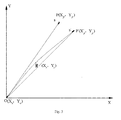
Figure 3 is the first schematic view of the articulated arm after the elastic deformation according to the present invention; -
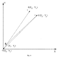
Figure 4 is the second schematic view of the articulated arm after the elastic deformation according to the present invention; -
Figure 5 is the third schematic view of the articulated arm after the elastic deformation according to the present invention; -
Figure 6 is a schematic view of a five-segment articulated arm after the elastic deformation according to the present invention; and -
Figure 7 is a schematic view of the control device of an articulated arm according to the present invention. - To make the above objects, features and advantages of the present invention clearer and easier to be understood, the present invention will be further detailed hereinafter in conjunction with the accompanying drawings and the embodiments.
- The present invention aims to achieve the following object: two or more tilt sensors are provided at different positions (for example, head end and tail end) of a mechanical arm, then the tilt sensors are used to measure an angle value to obtain the state parameters of the mechanical arm after its elastic deformation, the coordinate position parameters of the tail end after the elastic deformation are obtained via mathematic operation, and then mechanical act is controlled according to the position parameters of the tail end.
- Referring to
Figure 2 , it shows the control method of a mechanical articulated arm according to the present invention, comprising the following specific steps: - In Step S201, a tilt sensor is provided at the head end and the tail end of the mechanical articulated arm, respectively. Of course, the mounting positions of the tilt sensors can be determined according to the length of the mechanical articulated arm and the characteristics of its material, for example, the position can be at L/8, L/4 or L/2 of the articulated arm.
- In Step S202, the zero positions of the tilt sensors are calibrated when the articulated arm does not have elastic deformation, the positions of the tail end of the articulated arm before and after the elastic deformation are respectively set as point P and point P', and a point R is selected at the articulated arm. The zero positions refer to positions of the articulated arm when the articulated arm is placed at a stand having a complete supporting structure and in a state of having no elastic deformation, and the supporting structure can be horizontal and can also be inclined along the extending direction of the articulated arm, as long as it is ensured that the articulated arm can be completely supported and does not have elastic deformation.
- In Step S203, the tilt sensors are used to detect the angle values of the two different positions of the articulated arm before and after the elastic deformation and an angle offset Δθ of the articulated arm due to the elastic deformation is obtained, and a length parameter La and an angle parameter θa of the articulated arm after the deformation are calculated based on the angle offset Δθ and the length values of OR and RP' ;
- In Step S204, the position parameters X' p and Y ' p of the point P' are obtained according to the length parameter La and the angle parameter θa; and
- In Step S205, the action of the articulated arm is controlled according to the position parameters X' p and Y' p of the point P'.
- The present invention fully takes into consideration the elastic deformation of the articulated arm during the movement, and conducts reasoning and operating using the values of the angle changes of the articulated arm before and after the deformation, realizes more accurate and more reliable judgement on the state of the articulated arm, enhances the testability and controllability on the state of the articulated arm and then improves control precision.
- The following description takes a one-segment articulated arm as an example to detail the computing process of the present invention. As shown in
Figure 3 , suppose the direction in which the articulated arm does not have deformation is OP vector direction, and the articulated arm is along the ORP arc direction after the deformation. The point R is set as the midpoint position of the arc formed after the deformation of the articulated arm (the straight-line distance from the midpoint position to point O is equal to that from the midpoint position to the point P). Of course, in the situation that the deformation distribution of the articulated arm is known or can be detected, the point R may be approximately set as the point at the articulated arm that is farthest to an equivalent rigid articulated arm (the OP' segment) after the deformation (as shown in the followingFigure 4 ). In the situation that the point R is determined artificially, the lengths of OR and RP can also be measured, so that the broken line ORP can more approximately describe the state of the deformed articulated arm extending along the arc ORP'. - Furthermore, to better approximate the deformation of the articulated arm, sampling points M, N and R can be provided at different positions at the articulated arm, for example, at L/8, L/4 and L/2 of the articulated arm, then the broken line OMNRP can more approximately describe the deformation of the articulated arm OP, which substantively is a method of approximating a curve with a broken line, and the more the sampling points are, the higher the precision is. During practical application, the number of the sampling points on the one hand depends on cost of a sampling device and on the other hand depends on the sampling precision of the sampling device, and considering the two factors, a suitable solution can be selected according to the demand on the application precision.
- From
Figure 3 , the deformed articulated arm ORP can be equivalent to the rigid articulated arm OP', if the length and angle parameters of the OP' can be obtained, the problem of a flexible articulated arm can be transformed into the problem of solving the forward kinematics and the inverse kinematics of the rigid articulated arm. The following will describe how to calculate the precise coordinate parameter of the deformed articulated arm by using an angle difference measured with at least two tilt sensors provided in at least two positions at the mechanical articulated arm. - When the articulated arm only has minute deformation, the tilt sensors are preferably provided at the head end and the tail end of the articulated arm, referring to the position O and the position B (the positions when the articulated arm has not had deformation) or the position B' (the position when the articulated arm has had elastic deformation) in
Figure 3 , wherein the coordinate of the position B where the tilt sensor is located is known, the coordinate parameters can be described with the length parameter (i.e., the length parameter of the articulated arm) of OP and the angle parameter of OP, the deformation at the articulated point of the articulated arm is omitted, and the angle parameter of OP is approximately the angle value θ a0 measured by the tilt sensor A at the point A (seeFigure 5 ). - If the articulated arm OP is placed at a stand having a complete supporting structure so that the articulated arm is in a state of having no elastic deformation, it can be deemed that the angle parameter of OP can also be described with the angle value θ b0 measured by the tilt sensor B at point B, then when the mounting positions of tilt sensors A and B are completely parallel to the axial direction of the articulated arm, there exists the following equation:

- During practical application, as the mounting positions of the tilt sensors A and B may not be completely parallel to the axial direction of the articulated arm, this may result in initial deviations of the measurements of the two tilt sensors, that is,

- The measurements of the tilt sensors A and B when the articulated arm has not had elastic deformation are recorded as zero-position values which are respectively represented by θ a0 and θ b0.
- It is set that:

- That is,

- As shown in
Figure 4 , after the deformation of the articulated arm, the angle value of the articulated arm with respect to the zero position measured by the tilt sensor A is θ a1, the angle value of the articulated arm with respect to the zero position measured by the tilt sensor B is θ b1, the offset angle value of the articulated arm after the deformation is, considering the above description, the following equation can be established:
- From
Figure 4 , if the selection of the point R meets the condition that OR can be approximately the direction of the articulated arm before the elastic deformation, for ΔORP', the following equation can be established:
- The variation of the length parameter of the articulated arm when the articulated arm is deforming is omitted, for the length of the articulated arm, suppose |OP| = L is known, then:

- According to the triangle theorem, the following is rendered:

that is,
- The relationship "Δθ=∠1 + ∠2" is substituted into the above equation to render:

which is expanded to render:
that is,
- It is set that

so that
and also, as cos2 ∠2+ sin2 ∠2 =1,
the following can be rendered from the above:
- Thus, the parameters of the angle (θa ) and the length (La ) of the articulated arm can be obtained as follows:

and
the position of the tail end of the articulated arm after the deformation is:
- Therefore, the action of the articulated arm can be controlled using the position of the tail end of the articulated arm after the deformation, and this control manner fully takes into consideration the elastic deformation of the articulated arm and improves the precision of the control.
- For an articulated arm with two segments or more than two segments, it is only necessary to take the joint of the current segment with the last segment as the point O of the above coordinate, and its solving method can be implemented according to the method shown in the above equations 7 to 18.
- As shown in
Figure 6 , it takes the solution of a five-segment articulated arm as an example, and referring to the above method, the angle parameters θb , θc, θd and θe and the length parameters Lb , Lc, Ld and Le of the second segment 2#, the third segment 3#, the fourth segment 4# and the fifth segment 5# of the articulated arm can be sequentially obtained. - Thus, the coordinate parameters of the tail end of the articulated arm after the deformation are calculated as follow:

- Based on the above control method of a mechanical articulated arm, the present invention also provides a control device of a mechanical articulated arm, referring to
Figure 7 , it comprises an articulatedarm 11, and also comprises atilt sensor 12 and atilt sensor 13 provided on the articulatedarm 11, and acontroller 14 connected with thetilt sensor 12 and thetilt sensor 13, and thecontroller 14 comprises a calculatingunit 141 and adriving unit 142. - The calculating
unit 141 is used to calibrate the zero positions of the tilt sensors when the articulated arm does not have elastic deformation, the positions of the tail end of the articulated arm before and after the elastic deformation are respectively set as point P and point P', and a point R is selected at the articulated arm; the tilt sensors are used to detect the angle values of the two different positions of the articulated arm before and after the elastic deformation and an angle offset Δθ of the articulated arm due to the elastic deformation is obtained, and a length parameter La and an angle parameter θa of the articulated arm after the deformation are calculated based on the angle offset Δθ and the length values of OR and RP'; the position parameters X' p and Y ' p of the point P' are obtained according to the length parameter La and the angle parameter θa, and a driving amount is calculated according to the position parameters X' p and Y'p ; and thedriving unit 142 is used to control the action of the articulated arm according to the driving amount. - The control method and the control device of a mechanical articulated arm provided by the present invention are detailed hereinabove, in which specific examples are used to describe the principles and the embodiments of the present invention, and the above embodiments are just intended to help understand the method and the core thoughts of the present invention; meanwhile, for those skilled in the art, according to the thoughts of the present invention, the specific embodiments and the scope of application may be varied. In conclusion, the content of the description should not be understood as restrictions on the present invention.
Claims (11)
- A control method of a mechanical articulated arm, wherein at least arranges two tilt sensors are arranged at different positions of the articulated arm, and the method includes:calibrating the zero positions of the tilt sensors when the articulated arm does not have elastic deformation, setting that the positions of the tail end of the articulated arm are respectively point P and point P' before and after the elastic deformation, and selecting a point R at the articulated arm;using the tilt sensors to detect the angle values of the two different positions of the articulated arm before and after the elastic deformation, obtaining an angle offset Δθ of the articulated arm due to the elastic deformation, and calculating a length parameter La and an angle parameter θa of the articulated arm after the deformation based on the angle offset Δθ and the length values of OR and RP'; andobtaining the position parameters X' p and Y ' p of the point P' according to the length parameter La and the angle parameter θa, and controlling the action of the articulated arm according to the position parameters X' p and Y' p .
- The method according to claim 1, wherein at least two tilt sensors are provided at different positions of the articulated arm in the following way:two or more tilt sensors are provided at the head end and the tail end of each segment of the articulated arm, respectively.
- The method according to claim 2, wherein the point R selected at the articulated arm is the middle position of the arc formed after the elastic deformation of the articulated arm.
- The method according to claim 2, wherein the point R selected at the articulated arm is the point that is farthest to an equivalent rigid articulated arm formed after the elastic deformation of the articulated arm.
- The method according to claim 2, 3 or 4, wherein using the tilt sensors to detect the angle values of the two different positions of the articulated arm before and after the elastic deformation and obtaining an angle offset Δθ of the articulated arm due to the elastic deformation comprises the following steps:setting the angle values detected by the tilt sensors at the head end and the tail end of the articulated arm before the elastic deformation as θ a0 and θ b0' respectively, and setting an angle difference as Δθ 0 rendered due to that the mounting positions of the tilt sensors are not parallel to the axial direction of the articulated arm, then:

andsetting the position of the head end of the articulated arm as point O, using the tilt sensors to respectively detect the angle values of point O and point P' which are represented by θ a1 and θ b1, respectively, then calculating the angle offset Δθ as follow:
- The method according to claim 5, wherein calculating the length parameter La and the angle parameter θa of the articulated arm after the elastic deformation comprises the following steps:setting the angle values of ∠ROP' and ∠RP'O as L1 and L2, respectively, then:

according to the triangle theorem, the following is rendered:
substituting the formula "Δθ =∠1 + ∠2" to render: thereby obtaining the angle θa and the length La of the articulated arm:
- The method according to claim 6, wherein according to the length parameter La and the angle parameter θa, the position parameters X' p and Y ' p of the point P' can be specifically obtained as follows:

- A control device of a mechanical articulated arm comprising an articulated arm, wherein, further comprising at least two tilt sensors arranged at different positions of the articulated arm, and a controller connected with the tilt sensors; the controller comprising a calculating unit and a driving unit:the calculating unit being used to calibrate the zero positions of the tilt sensors when the articulated arm does not have elastic deformation, the positions of the tail end of the articulated arm before and after the elastic deformation being respectively set as point P and point P', a point R being selected at the articulated arm; the tilt sensors being used to detect the angle values of the two different positions of the articulated arm before and after the elastic deformation, an angle offset Δθ of the articulated arm due to the elastic deformation being obtained, and a length parameter La and an angle parameter θa of the articulated arm after the deformation being calculated based on the angle offset Δθ and the length values of OR and RP'; the position parameters X' p and Y ' p of the point P' being obtained according to the length parameter La and the angle parameter θa, and a driving amount being calculated according to the position parameters X' p and Y ' p andthe driving unit being used to control the action of the articulated arm according to the driving amount.
- The device according to claim 8, wherein at least two tilt sensors are provided at different positions of the articulated arm in the following way:two or more tilt sensors are provided at the head end and the tail end of each segment of the articulated arm, respectively.
- The device according to claim 8 or 9, wherein the point R selected at the articulated arm is the middle position of the arc formed after the elastic deformation of the articulated arm.
- The device according to claim 8 or 9, wherein the point R selected at the articulated arm is the point that is farthest to an equivalent rigid articulated arm formed after the elastic deformation of the articulated arm.
Applications Claiming Priority (2)
| Application Number | Priority Date | Filing Date | Title |
|---|---|---|---|
| CN2010102199280A CN101870110B (en) | 2010-07-01 | 2010-07-01 | Control method and control device of mechanical articulated arm |
| PCT/CN2011/076099 WO2012000400A1 (en) | 2010-07-01 | 2011-06-22 | Method and device for controlling mechanical articulated arm |
Publications (3)
| Publication Number | Publication Date |
|---|---|
| EP2589470A1 true EP2589470A1 (en) | 2013-05-08 |
| EP2589470A4 EP2589470A4 (en) | 2016-12-28 |
| EP2589470B1 EP2589470B1 (en) | 2018-09-12 |
Family
ID=42995281
Family Applications (1)
| Application Number | Title | Priority Date | Filing Date |
|---|---|---|---|
| EP11800145.2A Active EP2589470B1 (en) | 2010-07-01 | 2011-06-22 | Method and device for controlling mechanical articulated arm |
Country Status (4)
| Country | Link |
|---|---|
| US (1) | US9302392B2 (en) |
| EP (1) | EP2589470B1 (en) |
| CN (1) | CN101870110B (en) |
| WO (1) | WO2012000400A1 (en) |
Families Citing this family (15)
| Publication number | Priority date | Publication date | Assignee | Title |
|---|---|---|---|---|
| CN101870110B (en) | 2010-07-01 | 2012-01-04 | 三一重工股份有限公司 | Control method and control device of mechanical articulated arm |
| CN102152307B (en) * | 2011-01-24 | 2012-09-05 | 西安交通大学 | Inclination-angle-constraint-based kinematic calibration method for Stewart parallel robot |
| CN102346025B (en) * | 2011-07-12 | 2013-04-24 | 三一重工股份有限公司 | Method for obtaining terminal position parameters of arm frame system, arm frame system and engineering machinery |
| WO2013044463A1 (en) * | 2011-09-28 | 2013-04-04 | 长沙中联重工科技发展股份有限公司 | Mechanical arm, engineering machinery, and method for determining position of arm section of mechanical arm |
| CN102508494B (en) * | 2011-09-28 | 2014-12-24 | 中联重科股份有限公司 | Mechanical arm, engineering machinery and method for determining the position of the arm section of the mechanical arm |
| CN102589493B (en) * | 2012-02-08 | 2014-05-21 | 三一重工股份有限公司 | Cantilever crane system, engineering machinery and cantilever crane system terminal end location parameter obtaining method |
| CN104097206B (en) * | 2013-04-07 | 2016-08-17 | 同济大学 | The humanoid robot's all-around exercises self-balancing control method controlled based on momentum |
| CN103557823B (en) * | 2013-10-24 | 2016-07-06 | 中联重科股份有限公司 | Vibration displacement detection method, detection system, controller and equipment of cloth boom |
| CN104750116B (en) * | 2014-12-31 | 2017-07-07 | 中国航天科技集团公司第五研究院第五一三研究所 | A kind of paths planning method of Two-Arm Cooperating Robots operation |
| JP6470248B2 (en) | 2016-12-16 | 2019-02-13 | ファナック株式会社 | Teaching operation panel and robot system having the same |
| JP6999443B2 (en) * | 2018-02-16 | 2022-01-18 | 日本電産サンキョー株式会社 | How to calculate the correction value for industrial robots |
| CN109798859B (en) * | 2019-04-02 | 2023-05-26 | 福建远创喷码系统科技有限公司 | Automatic steel pipe measuring system and steel pipe measuring method |
| CN111975788B (en) * | 2020-01-03 | 2022-01-11 | 广东安达智能装备股份有限公司 | Calibration method of SCARA manipulator glue dispensing system |
| CN114637294B (en) * | 2022-03-14 | 2025-07-29 | Oppo广东移动通信有限公司 | Method and device for controlling movement of robot, robot and storage medium |
| CN114800502B (en) * | 2022-04-25 | 2024-06-21 | 上海睿尤准智控技术有限公司 | Arm support deformation compensation method, compensation control system and engineering mechanical equipment |
Family Cites Families (21)
| Publication number | Priority date | Publication date | Assignee | Title |
|---|---|---|---|---|
| US4570065A (en) * | 1983-01-28 | 1986-02-11 | Pryor Timothy R | Robotic compensation systems |
| US4710884A (en) * | 1984-12-19 | 1987-12-01 | Hitachi Construction Machinery Co., Ltd. | Device for compensating for deflection in a pliable positioning apparatus |
| DE4306127C2 (en) | 1993-02-27 | 2002-08-08 | Putzmeister Ag | Large manipulator, especially for truck-mounted concrete pumps |
| DE4412643A1 (en) | 1993-08-26 | 1995-03-02 | Putzmeister Maschf | Large manipulator, in particular for truck-mounted concrete pumps, and method for handling it |
| JPH11883A (en) * | 1997-06-13 | 1999-01-06 | Yaskawa Electric Corp | Automatic teaching method for robot movement, locus correcting method for robot, and control method for welding robot |
| JPH1185234A (en) * | 1997-08-30 | 1999-03-30 | Yaskawa Electric Corp | Device and method for correcting position of teaching point of automatic tool changer |
| JPH11165287A (en) | 1997-12-08 | 1999-06-22 | Yukio Saito | Attitude detection device, attitude control device, and robot control device |
| US6522952B1 (en) * | 1999-06-01 | 2003-02-18 | Japan As Represented By Secretary Of Agency Of Industrial Science And Technology | Method and system for controlling cooperative object-transporting robot |
| DE10107107A1 (en) * | 2001-02-14 | 2002-08-29 | Putzmeister Ag | Device for actuating an articulated mast of a large manipulator and large manipulator with such a device |
| DE10240180A1 (en) * | 2002-08-27 | 2004-03-11 | Putzmeister Ag | Device for actuating an articulated mast |
| CN1255249C (en) * | 2002-12-05 | 2006-05-10 | 上海交通大学 | On-line compensating method for locus coordinates of moving robot |
| CN100584547C (en) * | 2003-07-29 | 2010-01-27 | 松下电器产业株式会社 | The method of controlling the manipulator |
| CN101870108B (en) * | 2006-01-13 | 2011-09-28 | 松下电器产业株式会社 | Device for controlling robot arm |
| AT504257B1 (en) * | 2006-09-18 | 2008-06-15 | Univ Linz | DEVICE FOR CONTROLLING A ROBOT ARM |
| CN101522377B (en) | 2006-10-20 | 2011-09-14 | 株式会社日立制作所 | manipulator |
| CN100591880C (en) * | 2006-12-31 | 2010-02-24 | 三一重工股份有限公司 | An intelligent boom control device |
| DE102007012575A1 (en) * | 2007-03-13 | 2008-09-18 | Putzmeister Concrete Pumps Gmbh | large manipulator |
| JP4243326B2 (en) * | 2007-06-27 | 2009-03-25 | パナソニック株式会社 | Robot arm control device and control method, robot, and program |
| CN100549645C (en) * | 2008-05-21 | 2009-10-14 | 中国科学院合肥物质科学研究院 | Four-dimensional fingertip force sensor for underwater robot and its information acquisition method |
| CN101633168B (en) | 2009-07-28 | 2012-05-02 | 三一重工股份有限公司 | Control method and control system for large-scale engineering manipulator |
| CN101870110B (en) | 2010-07-01 | 2012-01-04 | 三一重工股份有限公司 | Control method and control device of mechanical articulated arm |
-
2010
- 2010-07-01 CN CN2010102199280A patent/CN101870110B/en active Active
-
2011
- 2011-06-22 US US13/807,220 patent/US9302392B2/en active Active
- 2011-06-22 EP EP11800145.2A patent/EP2589470B1/en active Active
- 2011-06-22 WO PCT/CN2011/076099 patent/WO2012000400A1/en not_active Ceased
Also Published As
| Publication number | Publication date |
|---|---|
| WO2012000400A1 (en) | 2012-01-05 |
| EP2589470A4 (en) | 2016-12-28 |
| US9302392B2 (en) | 2016-04-05 |
| US20130197695A1 (en) | 2013-08-01 |
| CN101870110A (en) | 2010-10-27 |
| CN101870110B (en) | 2012-01-04 |
| EP2589470B1 (en) | 2018-09-12 |
Similar Documents
| Publication | Publication Date | Title |
|---|---|---|
| EP2589470B1 (en) | Method and device for controlling mechanical articulated arm | |
| US11040445B2 (en) | Cartesian control of a boom tip of a large manipulator, in particular a concrete pump | |
| EP2377653B1 (en) | Method and system for controlling large-scale engineering manipulator | |
| EP3382105B1 (en) | Construction machine with calibration controller | |
| US9193573B1 (en) | Process for measuring and controlling extension of scissor linkage systems | |
| RU2497620C2 (en) | Method of control over roll bending machine for continuous bending of long variable-curvature radius billet and machine to this end | |
| US20190176325A1 (en) | An Error Modeling Method For End-Effector Space-Curve Trajectory Of Six Degree-of-Freedom Robots | |
| DE102013014626B4 (en) | Determination of the position of a movable measuring point on a machine | |
| EP2684836A1 (en) | Direction and speed control device for telescopic and articulated hydraulic lifting equipments. | |
| CN103302663B (en) | For having calibration steps and the calibration system of the robot of redundancy | |
| CN102508494B (en) | Mechanical arm, engineering machinery and method for determining the position of the arm section of the mechanical arm | |
| CN103792956B (en) | Method and device controlling spatial motion of intelligent arm | |
| CN102518445A (en) | Laser-oriented control system and method for shield machine | |
| CN112158587A (en) | Method for adjusting a workpiece gripping device and workpiece gripping device | |
| US20220049454A1 (en) | Grader and blade control method | |
| CN115628852A (en) | Multi-end centralized control linkage accurate leakage detection method and system based on TDLAS and holder | |
| WO2013000323A1 (en) | Hoisting measurement and control apparatus, method and construction machine | |
| CN102354213A (en) | Method, device and system for controlling boom end position of boom equipment | |
| CN201872171U (en) | Control device of a mechanical hinged arm | |
| CN103853172B (en) | Method and device for planning spatial motion of intelligent arm | |
| CN109209418A (en) | Development machine and its control method | |
| JP2589566B2 (en) | Automatic control system for tunnel lining machine | |
| KR101826577B1 (en) | The tool calibration method using robot's wrist axes movements | |
| CN221399125U (en) | Foundation pit inclination measurer | |
| CN104615014B (en) | The forecast Control Algorithm and system of pump truck cloth |
Legal Events
| Date | Code | Title | Description |
|---|---|---|---|
| PUAI | Public reference made under article 153(3) epc to a published international application that has entered the european phase |
Free format text: ORIGINAL CODE: 0009012 |
|
| 17P | Request for examination filed |
Effective date: 20130130 |
|
| AK | Designated contracting states |
Kind code of ref document: A1 Designated state(s): AL AT BE BG CH CY CZ DE DK EE ES FI FR GB GR HR HU IE IS IT LI LT LU LV MC MK MT NL NO PL PT RO RS SE SI SK SM TR |
|
| DAX | Request for extension of the european patent (deleted) | ||
| REG | Reference to a national code |
Ref country code: DE Ref legal event code: R079 Ref document number: 602011052022 Country of ref document: DE Free format text: PREVIOUS MAIN CLASS: B25J0013000000 Ipc: B25J0009160000 |
|
| RA4 | Supplementary search report drawn up and despatched (corrected) |
Effective date: 20161129 |
|
| RIC1 | Information provided on ipc code assigned before grant |
Ipc: B25J 9/16 20060101AFI20161123BHEP |
|
| GRAP | Despatch of communication of intention to grant a patent |
Free format text: ORIGINAL CODE: EPIDOSNIGR1 |
|
| STAA | Information on the status of an ep patent application or granted ep patent |
Free format text: STATUS: GRANT OF PATENT IS INTENDED |
|
| INTG | Intention to grant announced |
Effective date: 20180405 |
|
| GRAS | Grant fee paid |
Free format text: ORIGINAL CODE: EPIDOSNIGR3 |
|
| GRAA | (expected) grant |
Free format text: ORIGINAL CODE: 0009210 |
|
| STAA | Information on the status of an ep patent application or granted ep patent |
Free format text: STATUS: THE PATENT HAS BEEN GRANTED |
|
| AK | Designated contracting states |
Kind code of ref document: B1 Designated state(s): AL AT BE BG CH CY CZ DE DK EE ES FI FR GB GR HR HU IE IS IT LI LT LU LV MC MK MT NL NO PL PT RO RS SE SI SK SM TR |
|
| REG | Reference to a national code |
Ref country code: GB Ref legal event code: FG4D |
|
| REG | Reference to a national code |
Ref country code: CH Ref legal event code: EP |
|
| REG | Reference to a national code |
Ref country code: IE Ref legal event code: FG4D |
|
| REG | Reference to a national code |
Ref country code: DE Ref legal event code: R096 Ref document number: 602011052022 Country of ref document: DE |
|
| REG | Reference to a national code |
Ref country code: AT Ref legal event code: REF Ref document number: 1040000 Country of ref document: AT Kind code of ref document: T Effective date: 20181015 |
|
| REG | Reference to a national code |
Ref country code: NL Ref legal event code: MP Effective date: 20180912 |
|
| REG | Reference to a national code |
Ref country code: LT Ref legal event code: MG4D |
|
| PG25 | Lapsed in a contracting state [announced via postgrant information from national office to epo] |
Ref country code: SE Free format text: LAPSE BECAUSE OF FAILURE TO SUBMIT A TRANSLATION OF THE DESCRIPTION OR TO PAY THE FEE WITHIN THE PRESCRIBED TIME-LIMIT Effective date: 20180912 Ref country code: FI Free format text: LAPSE BECAUSE OF FAILURE TO SUBMIT A TRANSLATION OF THE DESCRIPTION OR TO PAY THE FEE WITHIN THE PRESCRIBED TIME-LIMIT Effective date: 20180912 Ref country code: NO Free format text: LAPSE BECAUSE OF FAILURE TO SUBMIT A TRANSLATION OF THE DESCRIPTION OR TO PAY THE FEE WITHIN THE PRESCRIBED TIME-LIMIT Effective date: 20181212 Ref country code: RS Free format text: LAPSE BECAUSE OF FAILURE TO SUBMIT A TRANSLATION OF THE DESCRIPTION OR TO PAY THE FEE WITHIN THE PRESCRIBED TIME-LIMIT Effective date: 20180912 Ref country code: GR Free format text: LAPSE BECAUSE OF FAILURE TO SUBMIT A TRANSLATION OF THE DESCRIPTION OR TO PAY THE FEE WITHIN THE PRESCRIBED TIME-LIMIT Effective date: 20181213 Ref country code: BG Free format text: LAPSE BECAUSE OF FAILURE TO SUBMIT A TRANSLATION OF THE DESCRIPTION OR TO PAY THE FEE WITHIN THE PRESCRIBED TIME-LIMIT Effective date: 20181212 Ref country code: LT Free format text: LAPSE BECAUSE OF FAILURE TO SUBMIT A TRANSLATION OF THE DESCRIPTION OR TO PAY THE FEE WITHIN THE PRESCRIBED TIME-LIMIT Effective date: 20180912 |
|
| PG25 | Lapsed in a contracting state [announced via postgrant information from national office to epo] |
Ref country code: HR Free format text: LAPSE BECAUSE OF FAILURE TO SUBMIT A TRANSLATION OF THE DESCRIPTION OR TO PAY THE FEE WITHIN THE PRESCRIBED TIME-LIMIT Effective date: 20180912 Ref country code: LV Free format text: LAPSE BECAUSE OF FAILURE TO SUBMIT A TRANSLATION OF THE DESCRIPTION OR TO PAY THE FEE WITHIN THE PRESCRIBED TIME-LIMIT Effective date: 20180912 Ref country code: AL Free format text: LAPSE BECAUSE OF FAILURE TO SUBMIT A TRANSLATION OF THE DESCRIPTION OR TO PAY THE FEE WITHIN THE PRESCRIBED TIME-LIMIT Effective date: 20180912 |
|
| REG | Reference to a national code |
Ref country code: AT Ref legal event code: MK05 Ref document number: 1040000 Country of ref document: AT Kind code of ref document: T Effective date: 20180912 |
|
| PG25 | Lapsed in a contracting state [announced via postgrant information from national office to epo] |
Ref country code: CZ Free format text: LAPSE BECAUSE OF FAILURE TO SUBMIT A TRANSLATION OF THE DESCRIPTION OR TO PAY THE FEE WITHIN THE PRESCRIBED TIME-LIMIT Effective date: 20180912 Ref country code: RO Free format text: LAPSE BECAUSE OF FAILURE TO SUBMIT A TRANSLATION OF THE DESCRIPTION OR TO PAY THE FEE WITHIN THE PRESCRIBED TIME-LIMIT Effective date: 20180912 Ref country code: ES Free format text: LAPSE BECAUSE OF FAILURE TO SUBMIT A TRANSLATION OF THE DESCRIPTION OR TO PAY THE FEE WITHIN THE PRESCRIBED TIME-LIMIT Effective date: 20180912 Ref country code: IS Free format text: LAPSE BECAUSE OF FAILURE TO SUBMIT A TRANSLATION OF THE DESCRIPTION OR TO PAY THE FEE WITHIN THE PRESCRIBED TIME-LIMIT Effective date: 20190112 Ref country code: PL Free format text: LAPSE BECAUSE OF FAILURE TO SUBMIT A TRANSLATION OF THE DESCRIPTION OR TO PAY THE FEE WITHIN THE PRESCRIBED TIME-LIMIT Effective date: 20180912 Ref country code: EE Free format text: LAPSE BECAUSE OF FAILURE TO SUBMIT A TRANSLATION OF THE DESCRIPTION OR TO PAY THE FEE WITHIN THE PRESCRIBED TIME-LIMIT Effective date: 20180912 Ref country code: NL Free format text: LAPSE BECAUSE OF FAILURE TO SUBMIT A TRANSLATION OF THE DESCRIPTION OR TO PAY THE FEE WITHIN THE PRESCRIBED TIME-LIMIT Effective date: 20180912 Ref country code: AT Free format text: LAPSE BECAUSE OF FAILURE TO SUBMIT A TRANSLATION OF THE DESCRIPTION OR TO PAY THE FEE WITHIN THE PRESCRIBED TIME-LIMIT Effective date: 20180912 Ref country code: IT Free format text: LAPSE BECAUSE OF FAILURE TO SUBMIT A TRANSLATION OF THE DESCRIPTION OR TO PAY THE FEE WITHIN THE PRESCRIBED TIME-LIMIT Effective date: 20180912 |
|
| PG25 | Lapsed in a contracting state [announced via postgrant information from national office to epo] |
Ref country code: SM Free format text: LAPSE BECAUSE OF FAILURE TO SUBMIT A TRANSLATION OF THE DESCRIPTION OR TO PAY THE FEE WITHIN THE PRESCRIBED TIME-LIMIT Effective date: 20180912 Ref country code: SK Free format text: LAPSE BECAUSE OF FAILURE TO SUBMIT A TRANSLATION OF THE DESCRIPTION OR TO PAY THE FEE WITHIN THE PRESCRIBED TIME-LIMIT Effective date: 20180912 Ref country code: PT Free format text: LAPSE BECAUSE OF FAILURE TO SUBMIT A TRANSLATION OF THE DESCRIPTION OR TO PAY THE FEE WITHIN THE PRESCRIBED TIME-LIMIT Effective date: 20190112 |
|
| REG | Reference to a national code |
Ref country code: DE Ref legal event code: R097 Ref document number: 602011052022 Country of ref document: DE |
|
| PLBE | No opposition filed within time limit |
Free format text: ORIGINAL CODE: 0009261 |
|
| STAA | Information on the status of an ep patent application or granted ep patent |
Free format text: STATUS: NO OPPOSITION FILED WITHIN TIME LIMIT |
|
| PG25 | Lapsed in a contracting state [announced via postgrant information from national office to epo] |
Ref country code: DK Free format text: LAPSE BECAUSE OF FAILURE TO SUBMIT A TRANSLATION OF THE DESCRIPTION OR TO PAY THE FEE WITHIN THE PRESCRIBED TIME-LIMIT Effective date: 20180912 |
|
| 26N | No opposition filed |
Effective date: 20190613 |
|
| PG25 | Lapsed in a contracting state [announced via postgrant information from national office to epo] |
Ref country code: SI Free format text: LAPSE BECAUSE OF FAILURE TO SUBMIT A TRANSLATION OF THE DESCRIPTION OR TO PAY THE FEE WITHIN THE PRESCRIBED TIME-LIMIT Effective date: 20180912 |
|
| PG25 | Lapsed in a contracting state [announced via postgrant information from national office to epo] |
Ref country code: MC Free format text: LAPSE BECAUSE OF FAILURE TO SUBMIT A TRANSLATION OF THE DESCRIPTION OR TO PAY THE FEE WITHIN THE PRESCRIBED TIME-LIMIT Effective date: 20180912 |
|
| REG | Reference to a national code |
Ref country code: CH Ref legal event code: PL |
|
| GBPC | Gb: european patent ceased through non-payment of renewal fee |
Effective date: 20190622 |
|
| REG | Reference to a national code |
Ref country code: BE Ref legal event code: MM Effective date: 20190630 |
|
| PG25 | Lapsed in a contracting state [announced via postgrant information from national office to epo] |
Ref country code: TR Free format text: LAPSE BECAUSE OF FAILURE TO SUBMIT A TRANSLATION OF THE DESCRIPTION OR TO PAY THE FEE WITHIN THE PRESCRIBED TIME-LIMIT Effective date: 20180912 |
|
| PG25 | Lapsed in a contracting state [announced via postgrant information from national office to epo] |
Ref country code: GB Free format text: LAPSE BECAUSE OF NON-PAYMENT OF DUE FEES Effective date: 20190622 Ref country code: IE Free format text: LAPSE BECAUSE OF NON-PAYMENT OF DUE FEES Effective date: 20190622 |
|
| PG25 | Lapsed in a contracting state [announced via postgrant information from national office to epo] |
Ref country code: BE Free format text: LAPSE BECAUSE OF NON-PAYMENT OF DUE FEES Effective date: 20190630 Ref country code: LU Free format text: LAPSE BECAUSE OF NON-PAYMENT OF DUE FEES Effective date: 20190622 Ref country code: CH Free format text: LAPSE BECAUSE OF NON-PAYMENT OF DUE FEES Effective date: 20190630 Ref country code: LI Free format text: LAPSE BECAUSE OF NON-PAYMENT OF DUE FEES Effective date: 20190630 |
|
| PG25 | Lapsed in a contracting state [announced via postgrant information from national office to epo] |
Ref country code: FR Free format text: LAPSE BECAUSE OF NON-PAYMENT OF DUE FEES Effective date: 20190630 |
|
| PG25 | Lapsed in a contracting state [announced via postgrant information from national office to epo] |
Ref country code: CY Free format text: LAPSE BECAUSE OF FAILURE TO SUBMIT A TRANSLATION OF THE DESCRIPTION OR TO PAY THE FEE WITHIN THE PRESCRIBED TIME-LIMIT Effective date: 20180912 |
|
| PG25 | Lapsed in a contracting state [announced via postgrant information from national office to epo] |
Ref country code: HU Free format text: LAPSE BECAUSE OF FAILURE TO SUBMIT A TRANSLATION OF THE DESCRIPTION OR TO PAY THE FEE WITHIN THE PRESCRIBED TIME-LIMIT; INVALID AB INITIO Effective date: 20110622 Ref country code: MT Free format text: LAPSE BECAUSE OF FAILURE TO SUBMIT A TRANSLATION OF THE DESCRIPTION OR TO PAY THE FEE WITHIN THE PRESCRIBED TIME-LIMIT Effective date: 20180912 |
|
| PG25 | Lapsed in a contracting state [announced via postgrant information from national office to epo] |
Ref country code: MK Free format text: LAPSE BECAUSE OF FAILURE TO SUBMIT A TRANSLATION OF THE DESCRIPTION OR TO PAY THE FEE WITHIN THE PRESCRIBED TIME-LIMIT Effective date: 20180912 |
|
| PGFP | Annual fee paid to national office [announced via postgrant information from national office to epo] |
Ref country code: DE Payment date: 20250617 Year of fee payment: 15 |