EP2589336A1 - Device for measuring the thickness of skin folds - Google Patents
Device for measuring the thickness of skin folds Download PDFInfo
- Publication number
- EP2589336A1 EP2589336A1 EP10809178.6A EP10809178A EP2589336A1 EP 2589336 A1 EP2589336 A1 EP 2589336A1 EP 10809178 A EP10809178 A EP 10809178A EP 2589336 A1 EP2589336 A1 EP 2589336A1
- Authority
- EP
- European Patent Office
- Prior art keywords
- measuring
- thickness
- jaws
- constant force
- skin folds
- Prior art date
- Legal status (The legal status is an assumption and is not a legal conclusion. Google has not performed a legal analysis and makes no representation as to the accuracy of the status listed.)
- Granted
Links
Images







Classifications
-
- A—HUMAN NECESSITIES
- A61—MEDICAL OR VETERINARY SCIENCE; HYGIENE
- A61B—DIAGNOSIS; SURGERY; IDENTIFICATION
- A61B5/00—Measuring for diagnostic purposes; Identification of persons
- A61B5/103—Measuring devices for testing the shape, pattern, colour, size or movement of the body or parts thereof, for diagnostic purposes
- A61B5/107—Measuring physical dimensions, e.g. size of the entire body or parts thereof
- A61B5/1075—Measuring physical dimensions, e.g. size of the entire body or parts thereof for measuring dimensions by non-invasive methods, e.g. for determining thickness of tissue layer
-
- A—HUMAN NECESSITIES
- A61—MEDICAL OR VETERINARY SCIENCE; HYGIENE
- A61B—DIAGNOSIS; SURGERY; IDENTIFICATION
- A61B5/00—Measuring for diagnostic purposes; Identification of persons
- A61B5/103—Measuring devices for testing the shape, pattern, colour, size or movement of the body or parts thereof, for diagnostic purposes
- A61B5/107—Measuring physical dimensions, e.g. size of the entire body or parts thereof
- A61B5/1072—Measuring physical dimensions, e.g. size of the entire body or parts thereof measuring distances on the body, e.g. measuring length, height or thickness
-
- A—HUMAN NECESSITIES
- A61—MEDICAL OR VETERINARY SCIENCE; HYGIENE
- A61B—DIAGNOSIS; SURGERY; IDENTIFICATION
- A61B5/00—Measuring for diagnostic purposes; Identification of persons
- A61B5/0048—Detecting, measuring or recording by applying mechanical forces or stimuli
- A61B5/0053—Detecting, measuring or recording by applying mechanical forces or stimuli by applying pressure, e.g. compression, indentation, palpation, grasping, gauging
-
- A—HUMAN NECESSITIES
- A61—MEDICAL OR VETERINARY SCIENCE; HYGIENE
- A61B—DIAGNOSIS; SURGERY; IDENTIFICATION
- A61B5/00—Measuring for diagnostic purposes; Identification of persons
- A61B5/44—Detecting, measuring or recording for evaluating the integumentary system, e.g. skin, hair or nails
- A61B5/441—Skin evaluation, e.g. for skin disorder diagnosis
- A61B5/442—Evaluating skin mechanical properties, e.g. elasticity, hardness, texture, wrinkle assessment
-
- A—HUMAN NECESSITIES
- A61—MEDICAL OR VETERINARY SCIENCE; HYGIENE
- A61B—DIAGNOSIS; SURGERY; IDENTIFICATION
- A61B5/00—Measuring for diagnostic purposes; Identification of persons
- A61B5/48—Other medical applications
- A61B5/4869—Determining body composition
- A61B5/4872—Body fat
-
- G—PHYSICS
- G01—MEASURING; TESTING
- G01B—MEASURING LENGTH, THICKNESS OR SIMILAR LINEAR DIMENSIONS; MEASURING ANGLES; MEASURING AREAS; MEASURING IRREGULARITIES OF SURFACES OR CONTOURS
- G01B3/00—Measuring instruments characterised by the use of mechanical techniques
- G01B3/002—Details
- G01B3/008—Arrangements for controlling the measuring force
-
- G—PHYSICS
- G01—MEASURING; TESTING
- G01B—MEASURING LENGTH, THICKNESS OR SIMILAR LINEAR DIMENSIONS; MEASURING ANGLES; MEASURING AREAS; MEASURING IRREGULARITIES OF SURFACES OR CONTOURS
- G01B3/00—Measuring instruments characterised by the use of mechanical techniques
- G01B3/16—Compasses, i.e. with a pair of pivoted arms
-
- A—HUMAN NECESSITIES
- A61—MEDICAL OR VETERINARY SCIENCE; HYGIENE
- A61B—DIAGNOSIS; SURGERY; IDENTIFICATION
- A61B5/00—Measuring for diagnostic purposes; Identification of persons
- A61B5/0002—Remote monitoring of patients using telemetry, e.g. transmission of vital signals via a communication network
Definitions
- the constant force actuator (11) comprises a crescent shaped saddle (11A) which supports at least one constant force elastic element (11D), two drums (11C1) and (11C2), two bearings (11B1) and (11B2), two rotation axes (11E1) and (11E2).
- the device for measuring skinfold thickness has a large centre distance of the jaws rotation axes and comprises one cam for compensation of variations in the jaws force arm length, one constant force actuator (11) and one orientation mechanism for the end tips (1A and 1B), permitting measurement of skinfold thickness of at least 110 mm, with application of a constant pressure to the skin folds.
- the device for measuring skinfold thickness comprises a mechanism for transmission of movement to the end tips based on the following systems: one parallelogram shaped mechanism with bars in tension and/or compression, one inextensible cable mechanism under tension by elastic element action and one flexible element mechanism confined in its housing.
- the elastic element of the constant force actuator (11D) is based on a constant force spring.
- the device for measuring skinfold thickness incorporates a mechanism for multiplying the jaws angular displacement that is able to increase the resolution of the measurement of the distance between the faces of the end tips (1A and 1B).
- the device housing (12A and 12B) accommodates all the mechanical elements for the transmission of the force of the constant force actuator (11) to the jaws (3A and 3B), the sensing elements (10A and 10B) and the electronic system (20).
- the device for measuring skinfold thickness has hinged and oriented end tips (1A and 1B) preferentially with contact surfaces that are kept parallel by means of a mechanism actuated by the jaws (3A and 3B) opening/closing, the said end tips being thereby able to apply a constant pressure to the skinfold under measurement.
- the device for measuring skinfold thickness also comprises one electronic system integrating one rechargeable power supply system, one signal conditioning system, one dedicated microcontroller and one wireless communication system.
- the device for measuring skinfold thickness also comprises one window (21) which permits wireless communication with a remote station and the visualization of light indicators for user information.
- the device for measuring skinfold thickness comprises one on/off switch, one display and one navigation system all located in the device symmetry plan, in order to make the handling of the said device independent of the dominant hand of the operator.
- the developed apparatus uses working principles of a device for measuring skinfold thickness, integrating some additional elements for improving its accuracy and measuring range. It is a device for measuring skinfold thickness comprising one closed housing with a cylindrical part (12B) and a handle extension (12A), one structure with two jaws (3A and 3B) with hinged end tips (1A and 1B) and a lever (16).
- the device housing (12A and 12B) includes all the mechanical elements of force transmission from the constant force actuator (11) to the jaws (3A and 3B), the sensing element (10A and 10B), a power supply (13) as for example a battery, its power charging jack (14) and the electronic system (20).
- the cylindrical housing (12B) has a window (21) which permits a preferential embodiment for wireless communication with a remote station and the visualization of three light indicators which inform the user about the device on/off state, the on/off state of the communication with the remote station and the charge level of the power supply.
- the jaws (3A and 3B) have rotation axes (6A and 6B) and extension shields inside the cylindrical housing (12B).
- the jaws are manipulated using the handle (12A) and the lever (16), jaw closure being controlled by one transmission chain connected at the other end to the constant force actuator (11).
- the constant force actuator (11) installed in the device housing handle (12A) has the main function of imposing a constant pressure on the contact faces of the end tips (1A and 1B) with the skinfold under measurement. Additionally it ensures the return movement of the jaws (3A and 3B) during closure, while also eliminating mechanical backlash along the transmission chain.
- the constant force actuator (11) applies the force to the jaw (3B) by means, for example, of one inextensible cable (7) in contact with one cam (4), attached to the jaw (3B). Both jaws (3A and 3B) are interconnected by mechanical elements (5A and 5B) that accomplish their simultaneous opening.
- the increase of the maximum opening distance between end tips (1A and 1B) can also be achieved by providing the jaws (3A and 3B) with a larger angular opening. That is possible in this device, because it incorporates a rotating end tip (1A and 1B) mechanism which ensures the parallelism between their contact faces.
- the geometry of the jaws (3A and 3B) hinges minimizes the movement for accommodation of the position of the end tips (1A and 1B) by means of a large centre distance of the jaws (3A and 3B) hinges. Due to this the variation of the length of the force arm is minimized and the maximum value of the said length occurs at an intermediate point between the maximum aperture and total closure of the jaws (3A and 3B).
- This value is considerably higher than that achieved by devices available in the market whose maximum skinfold thickness measurement does not usually exceed 80 mm.
- the end tips (1A and 1B) are hinged at the rotation axes (2A and 2B) in the extremities of the jaws (3A and 3B), respectively, keeping their clamping surfaces parallel to each other.
- the said parallelism is achieved by a movement transmission mechanism, it is independent of the opening angle of the jaws(3A and 3B) and it provides a constant uniform pressure on the whole contact area between the end tip clamping surfaces and the skinfold.
- skinfold callipers available in the market either have end tips rigidly linked to the jaws or they do not have any parallelism control mechanism. When the end tips are rigidly linked to the jaws, they will not remain parallel to each other, and so the pressure applied to the skinfold is not uniform.
- End tips with free rotation and without any mechanism for enforcing parallelism are not able to correctly control the positioning of the clamping surfaces of the end tips. Consequently they do not comply with the established protocol that prescribes a uniformly distributed pressure of 10 gf/mm2.
- the movement transmission mechanism for keeping the said parallelism is based on the following systems: one parallelogram shaped mechanism with bars in tension and/or compression; one inextensible cable mechanism kept under tension by the action of an elastic element and one flexible element mechanism confined in its housing.
- the measurement of the distance between the clamping surface of the end tips (1A) and (1B) is performed by a sensing element (10A and 10B) integrated in the transmission chain between the constant force actuator (11) and the jaws (3A and 3B).
- the actuation of the sensing element (10A and 10B) is achieved through a displacement multiplication mechanism consisting in the elements (5B) and (19), which increases the resolution of the measurement of the distance between the end tip faces, for any given resolution of the encoder (10A and 10B).
- the backlash of the said multiplication mechanism (5B and 19) is eliminated by a spiral spring (18).
- the button (17) for triggering the time interval according to the protocol for the skinfold clamping procedure and another button (15) is located, for example, at the lever (16) tail end for resetting the measurement to the zero value.
- the device on/off button (8) and a navigation system (9) which permits remote interaction with the graphical interface of the software application.
- the said system is based on a navigation button (9) or a touchscreen (9B).
- the constant force actuator (11) is based on an elastic element of constant force (11D).
- the said actuator multiplies the force of the elastic element of constant force (11D) by use of the said element with both ends winded on drums (11C1) and (11C2), supported by bearings (11B1) and (11B2) whose internal races are linked to the rotation axes (11E1) and (11E2), respectively.
- the force is conveyed to the transmission chain by a crescent shaped saddle (11A) on which the constant force elastic element (11D) rests.
- the extremity of the handle (12A) houses the power supply (13) with the respective power charging jack (14).
- the electronic system (20) in its distinct configurations can be composed by one power supply charging system, one signal conditioning system, one dedicated microcontroller, one display for data presentation (43) and one wireless communication system. It is responsible for the management of the whole device: it receives the operator commands through the buttons (8), (15), (17) and either from the navigation button (9A) or the touchscreen (9B), power supply level information, wireless communication data and sensing element data (10B). In accordance it controls the information supplied to the operator through the light indicators (23), (24) and (25), through the display (43) for data presentation and it is responsible for establishing the communication with the software application residing in the remote station.
- the information conveyed by the navigation button (9A) or by the touchscreen (9B) can be transmitted to the remote communication station to remotely operate the graphical interface of the software application.
- This functionality can be seen as complementary to the use of input devices directly connected to the remote communication station, such as: keyboard, mouse and tactile screen. This is intended to expedite the measurement procedures, reducing the time waste resulting from the recurring access to the peripherals of the remote communication station for triggering the computer application commands.
- the device ergonomic configuration offers considerable free lateral areas (22) on the jaws (3A and 3B), on the cylindrical housing (12B) and on the handle (12A), which are appropriate for displaying advertising elements.
- the electronic system (20) By pressing button (8) the electronic system (20) is activated and this state is signalled by the light indicator (24).
- the electronic system (20) presents data for interaction with the operator through the display device and can establish contact through its wireless communication system with the remote station, which will be signalled by the flashing of the light indicator (25).
- the battery charge level can be visualized through the indicator (23). Insufficient charge level is reported to the computational application.
- a compatible external power supply system For recharging the device battery a compatible external power supply system is simply plugged to the charging jack (14). The battery charge level evolution is monitored by the evolution of the light indicator (23).
- the release of the force on the lever (16) permits the adjustment of the clamping surface of the end tips (1A and 1B) to the skinfold under measurement.
- the pressure exerted by the tips on the skinfold comes exclusively from the constant force actuator (11), transmitted by the kinematic chain.
- the start of the time interval defined in the protocol is triggered by releasing the pressure on button (17).
- the skinfold thickness is measured by the distance between the contact surface of the end tips (1A and 1B), this information being transmitted to the encoded sensing element (10A) through the kinematic chain (1B, 3B, 5B and 19).
- the sensing reading element (10B) transmits the reading information to the dedicated microcontroller. After being processed by the dedicated microcontroller, all the information concerning the measurement is transmitted by the display (43). This information can be transmitted by wireless communication to the computer application in the remote station.
- the interaction with the computer application can be made using the navigation button (9A) or the touchscreen (9B).
- the command conveyed by the release of button (17) for starting the protocol time interval is processed by the dedicated microcontroller, triggering a real time counting of the protocol time interval, whose beginning and end information is presented on the display (43) and transmitted to the computer application by wireless communication.
- this constant force actuator mechanism is located in the device handle (12A) and comprises one crescent shaped saddle (11A), two drums (11C1) and (12C2), two bearings (11B1) and (11B2), two rotation axes (11E1) and (11E2) and one constant force spring (11D).
- the constant force actuator (11) is based on a constant force spring (11D). It doubles the force of the spring (11D) by coiling both its ends over drums (11C1) and (11C2), supported by bearings (11B1) and (11B2) whose inner races are connected to the axes of rotation (11E1) and (11E2), respectively.
- the natural tendency of the spring is to wrap around the drums (11C1) and (11C2) thus exerting a tensile force at the end of the coupling.
- This force is conveyed to the transmission chain through a crescent shaped saddle (11A) on which rests the elastic element of constant force (11D), the saddle being pulled by the inextensible cable (7).
- Example 2 referring to figure 4 : this mechanism is present in both jaws and equally applied. It consists of a primary parallelogram and a secondary parallelogram.
- the primary parallelogram consists of two pairs of parallel line segments: the first pair is formed by the line segment between the axes of rotation (27A) and (31A) and the line segment between the axes of rotation (6A) and (30A); the second pair is formed by the line segment between the axes of rotation (27A) and (6A) and the line segment between the axes of rotation (31A) and (30A).
- the secondary parallelogram is composed by two pairs of parallel line segments: the first is formed by the line segment between the axes of rotation (32A) and (33A) and the line segment between the axes of rotation (30A) and (2A); the second is formed by the line segment between the axes of rotation (32A) and (30A) and the line segment between the axes of rotation (33A) and (2A).
- the axes (27A) and (6A) are fixed to the device body, the axes (30A) and (2A) are fixed to the jaw (3A), while the remaining axes (31A), (32A) and (33A) are floating and can move relative to the device housing (12B) and the jaw (3A).
- the mechanism installed in the jaw (3B) is identical to that described previously, changing the reference from A to B, with the exception of that of the device housing (12B).
- the secondary parallelogram side between the axes (30A) and (32A) is defined in the coupling element (28A), on which is also defined the side of the primary parallelogram between the axes (30A) and (31A), the relative position of these two segments remains unchanged throughout the movement of the jaw (3A).
- the secondary parallelogram side between the axes (2a) and (33A) is forced to maintain its angular position relative to the side between the axes (27A) and (6A) of the primary parallelogram.
- the end tip face (1A) and the secondary parallelogram side between the axes of rotation (2A) and (33A) are defined in the same part, the end tip (1A), forcing the end tip face to keep its angular position in relation to the device housing (12B).
- the mechanism located on the jaw (3B) its operation is analogous to that just described for the jaw (3A).
- Example 3 referring to figure 5 : the description of the mechanism pertaining to this example is similar to that of the mechanism of example 2.
- the replacement of the elements (26A) and (29A) by inextensible cables (34A) and (35A) requires the introduction of an elastic element (36A) for keeping these two inextensible cables always in tension whatever the opening of the jaws (3A and 3B).
- the mechanism installed in the jaw (3B) is identical to that described previously, changing the reference from A to B.
- either one of the inextensible cables (34A) and (35A) located in each of the jaws (3A) and (3B), can be replaced by a rigid bar.
- Example 4 referring to figure 6 : the length of the path between the anchoring points (27A) and (39A), established by the inextensible cable (37A) pulled tight by the action of the elastic element (38A), will remain constant whatever the jaw (3A) angle. Due to the equal length of the line segment between the axis (6A) and the anchoring point (27A) and the one between the axis (2A) and the anchoring point (39A) and given that the anchoring point (27A) is fixed to the device housing (12B), the faces of the end tips (1A) and (1B) remain parallel to each other during the movement of the jaws (3A and 3B), and only have translation movement relative to the device housing.
- the mechanism installed in the jaw (3B) is identical to that described previously, changing the reference from A to B, with the exception of that of the device housing (12B).
- Example 5 referring to figure 7 : the length of the path e between the anchoring points (27A) and (39A) established through a flexible element (40A) confined in its housing (41A), remains constant whatever the jaw (3A) angle.
- the flexible element (40A) works in compression and is confined in its housing (41A) in jaw (3A), with sliding clearance.
- the mechanism installed in the jaw (3B) is identical to that described previously, changing the reference from A to B, with the exception of that of the device housing (12B).
- Example 6 referring to figure 8 : the joystick-type navigation button (9A) triggers five distinct command actions on the software application cursor, allowing the operator to navigate the graphical interface. There are four steering actions and the fifth is for selection confirmation.
- Example 7 referring to figure 9 the touchscreen (9B) triggers directional movements of the software application cursor, as a result of operator sliding actions on its surface.
- the confirmation of the selection is achieved by a touch on the touchscreen.
- Example 8 referring to figure 11 : the mechanism for simultaneous opening of the jaws (3A and 3B) is located inside the device housing (12B) and comprises two toothed sectors (44A and 44B) with equal pitch circle attached to the jaws (3A and 3B) and with rotation axes (6A and 6B), respectively.
- the rotation imposed on the sector (44B) by the action of the lever (16) transmits the motion to the toothed sector (44A) leading to the simultaneous opening of the two jaws (3A and 3B) and with equal amplitude.
- this mechanism for simultaneous opening of the jaws (3A and 3B) is located inside the device housing (12B) and consists of a hinged four-bar mechanism embodied by: a line segment between the axes (6A) and (47), a line segment between the axes (6B) and (46), a transmission bar (45) articulated between the axes (46) and (47) attached to the jaws (3A and 3B) and a bar materialized by the device housing (12B) between the axes (6A) and (6B).
- the rotation of the lever (16) leads to the rotation of the segment between the axes (46) and (6B) around the axis (6B), which in turn forces the displacement of the transmission bar (45), causing the rotation of the segment lying between the axes (47) and (6A) around the axis (6A) and the consequent rotation of the jaw (3A) with an amplitude equal to that of the jaw (3B).
- These rotations have the same amplitude since the line segments included between the pairs of axes (6A and 47) and (6B and 46) are of equal length.
Landscapes
- Health & Medical Sciences (AREA)
- Life Sciences & Earth Sciences (AREA)
- Physics & Mathematics (AREA)
- Medical Informatics (AREA)
- Surgery (AREA)
- Biophysics (AREA)
- Pathology (AREA)
- Engineering & Computer Science (AREA)
- Biomedical Technology (AREA)
- Heart & Thoracic Surgery (AREA)
- Veterinary Medicine (AREA)
- Molecular Biology (AREA)
- Public Health (AREA)
- Animal Behavior & Ethology (AREA)
- General Health & Medical Sciences (AREA)
- Oral & Maxillofacial Surgery (AREA)
- Dentistry (AREA)
- General Physics & Mathematics (AREA)
- Dermatology (AREA)
- Measurement Of The Respiration, Hearing Ability, Form, And Blood Characteristics Of Living Organisms (AREA)
- A Measuring Device Byusing Mechanical Method (AREA)
Abstract
Description
- The investigation of the state of the art disclosed three patent documents considered as the closest "prior art".
- Devices for measuring skinfold thickness are known in the state of the art. Such is the case of the device described in the patent document
US3008239 referring to an apparatus for measuring skinfold thickness with jaws prepared for applying constant force. However this patent does not describe the mechanism generating constant force, which is one of the aims of the present invention and which permits to multiply the spring force. - The patent document
US4315372 also describes a device for measuring skinfold thickness with C-shaped jaws and also incorporating a spring in a central position that permits the application of constant force. As in the previous document this patent document does not describe the mechanism for the constant force actuator that is one of the aims of the present invention. - Finally, the document
WO9317297 - It is the objective of the present invention to describe a device for measuring skinfold thickness which comprises:
- one device housing (12B), preferably of closed cylindrical shape, with a device handle (12A);
- one structure with two jaws (3A and 3B) with hinged and mechanically oriented end tips (1A and 1B), and one lever (16);
- one constant force actuator mechanism (11);
- one cam (4) with a profile that compensates the variation of the force arm length in the jaws (3A and 3B) and which provides the transmission of the force generated by the said constant force actuator (11).
- In a preferential embodiment of the device for measuring skinfold thickness in the present invention, the constant force actuator (11) comprises a crescent shaped saddle (11A) which supports at least one constant force elastic element (11D), two drums (11C1) and (11C2), two bearings (11B1) and (11B2), two rotation axes (11E1) and (11E2).
- In other embodiment even more preferential the device for measuring skinfold thickness has a large centre distance of the jaws rotation axes and comprises one cam for compensation of variations in the jaws force arm length, one constant force actuator (11) and one orientation mechanism for the end tips (1A and 1B), permitting measurement of skinfold thickness of at least 110 mm, with application of a constant pressure to the skin folds.
- In other preferential embodiment the device for measuring skinfold thickness comprises a mechanism for transmission of movement to the end tips based on the following systems: one parallelogram shaped mechanism with bars in tension and/or compression, one inextensible cable mechanism under tension by elastic element action and one flexible element mechanism confined in its housing.
- In an embodiment even more preferential of the device for measuring skinfold thickness object of the present invention, the elastic element of the constant force actuator (11D) is based on a constant force spring.
- In other embodiment even more preferential the device for measuring skinfold thickness incorporates a mechanism for multiplying the jaws angular displacement that is able to increase the resolution of the measurement of the distance between the faces of the end tips (1A and 1B).
- In other embodiment even more preferential of the device for measuring skinfold thickness the device housing (12A and 12B) accommodates all the mechanical elements for the transmission of the force of the constant force actuator (11) to the jaws (3A and 3B), the sensing elements (10A and 10B) and the electronic system (20).
- In other embodiment even more preferential of the device for measuring skinfold thickness, it has hinged and oriented end tips (1A and 1B) preferentially with contact surfaces that are kept parallel by means of a mechanism actuated by the jaws (3A and 3B) opening/closing, the said end tips being thereby able to apply a constant pressure to the skinfold under measurement.
- In other preferential embodiment the device for measuring skinfold thickness also comprises one electronic system integrating one rechargeable power supply system, one signal conditioning system, one dedicated microcontroller and one wireless communication system.
- In other embodiment even more preferential the device for measuring skinfold thickness also comprises one window (21) which permits wireless communication with a remote station and the visualization of light indicators for user information.
- In other embodiment even more preferential the device for measuring skinfold thickness comprises one on/off switch, one display and one navigation system all located in the device symmetry plan, in order to make the handling of the said device independent of the dominant hand of the operator.
- For better understanding of the invention figures are included in annex, which represent preferential embodiments of the invention but are not intended to limit the object of the present invention.
-
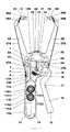
Figure 1A and1B : Representation of the device.- 1A and 1B - End tip A and B, respectively;
- 2A and 2B - Axis of rotation of the end tip A and B, respectively;
- 3A and 3B - Jaw A and B, respectively;
- 4 - Force compensation cam;
- 5A and 5B - Mechanical transmission elements A and B, respectively;
- 6A and 6B - Axis of rotation of the jaw A and B, respectively;
- 7 - Inextensible cable;
- 8 -On/off switch;
- 9 - Device for remote interaction;
- 10A - Encoded sensing element;
- 10B - Reading sensing element;
- 11 - Constant force actuator;
- 12A - Device handle;
- 12B - Device cylindrical body;
- 13 - Power supply;
- 14 - Power charging jack;
- 15 - Measurement reset button;
- 16 - Lever;
- 17 - Trigger button for the time interval of the measurement protocol;
- 18 - Spiral spring of the encoded sensing element;
- 19 - Mechanical element for increasing the measurement resolution;
- 20 - Electronic system;
- 21 - Window for communication and visualization of the light indicators;
- 22 - Device lateral faces;
- 23 - Light indicator of the device power supply status;
- 24 - Light indicator of the on/off status of the electronic system (20);
- 25 - Light indicator of the on/off status of the device connection to the remote station.
-
Figure 2 : Representation of the device internal constitution.- 1A and 1B - End tip A and B, respectively;
- 2A and 2B - Axis of rotation of end tip A and B, respectively;
- 3A and 3B - Jaw A and B, respectively;
- 4 - Force compensation cam;
- 5A and 5B - Mechanical transmission element A and B, respectively;
- 6A and 6B - Axis of rotation of jaw A and B, respectively;
- 7 - Inextensible cable;
- 8 - On/off switch;
- 9 - Device for remote interaction;
- 10A - Encoded sensing element;
- 10B - Reading sensing element;
- 11A - Crescent shaped saddle;
- 11B1 and 11B2 - Bearing for support of winding drum (11C1 and 11C2), respectively;
- 11C1 and 11C2 - Winding drum for the ends of the elastic element of constant force (11D);
- 11D - Elastic element of constant force;
- 11E1 and 11E2 - Axis of rotation of the bearing (11B1 and 11B2), respectively;
- 12A - Device handle;
- 12B - Device cylindrical body;
- 13 - Power supply;
- 14 - Power charging jack;
- 15 - Measurement reset button;
- 16 - Lever;
- 17 - Trigger button for the time interval of the measurement protocol;
- 18 - Spiral spring of the encoded sensing element;
- 19 - Mechanical element for increasing measurement resolution;
- 20 - Electronic system;
- 21 - Window for communication and visualization of the light indicators;
- 22 - Device lateral faces;
- 23 - Light indicator of the device power supply status;
- 24 - Light indicator of the on/off status of the electronic system (20);
- 25 - Light indicator of the on/off status of the device connection to the remote station;
- 27A and 27B - Fixed axis of rotation of the bars (26A and 26B), respectively;
- 37A and 37B - Inextensible cable located in jaw (3A and 3B), respectively;
- 38A and 38B - Elastic element located in jaw (3A and 3B), respectively;
- 39A and 39B - Anchoring point of the inextensible cable (37A and 37B) on the end tip (1A and 1B), respectively.
-
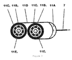
Figure 3 : Representation of a mechanism called constant force actuator (11), with the following components:- 7 - Inextensible cable;
- 11A - Crescent shaped saddle;
- 11B1 and 11B2 - Bearing for support of winding drum (11C1 and 11C2), respectively;
- 11C1 and 11C2 - Winding drum for the ends of the elastic element of constant force (11D);
- 11D - Elastic element of constant force;
- 11E1 and 11E2 - Axis of rotation of the bearing (11B1 and 11B2), respectively;
-
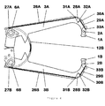
Figure 4 : Representation of a transmission mechanism of angular movement to the end tips, for maintaining the parallelism of their clamping faces, using a parallelogram based configuration with bars in compression, with the following components:- 1A and 1B - End tip A and B, respectively;
- 2A and 2B - Axis of rotation of the end tip A and B, respectively;
- 3A and 3B - Jaw A and B, respectively;
- 6A and 6B - Axis of rotation of the jaw A and B, respectively;
- 12B - Device cylindrical body;
- 26A and 26B - Primary parallelogram bar A and B, respectively;
- 27A and 27B - Fixed axis of rotation of the bars (26A and 26B), respectively;
- 28A and 28B - Coupling element located in jaw (3A and 3B), respectively;
- 29A and 29B - Secondary parallelogram bar A and B, respectively;
- 30A and 30B - Fixed axis of rotation of the coupling element (28A and 28B), respectively;
- 31A and 31B - Floating hinge of the primary bar (26A and 26B) in the coupling element (28A and 28B), respectively;
- 32A and 32B - Floating hinge of the secondary bar (29A and 29B) in the coupling element (28A and 28B), respectively;
- 33A and 33B - Floating hinge of the secondary bar (29A and 29B) in the end tip (1A and 1B), respectively.
-
Figure 5 : Representation of a transmission mechanism of angular movement to the end tips, for maintaining the parallelism of their clamping faces, using a parallelogram based configuration with bars in tension and/or compression, with the following components:- 1A and 1B - End tip A and B, respectively;
- 2A and 2B - Axis of rotation of end tip A and B, respectively;
- 3A and 3B - Jaw A and B, respectively;
- 6A and 6B - Axis of rotation of jaw A and B, respectively;
- 27A and 27B - Fixed axis of rotation of the inextensible cable/bar (34A and 34B), respectively;
- 28A and 28B - Coupling element located in jaw (3A and 3B), respectively;
- 30A and 30B - Fixed axis of rotation of the coupling element (28A and 28B), respectively;
- 31A and 31B - Floating hinge of the inextensible cable/primary bar (34A and 34B) in the coupling element (28A and 28B), respectively;
- 32A and 32B - Floating hinge of the inextensible cable/secondary bar (35A and 35B) in the coupling element (28A and 28B), respectively;
- 33A and 33B - Floating hinge of the inextensible cable/secondary bar (35A and 35B) in the end tip (1A and 1B), respectively;
- 34A and 34B - Inextensible cable/primary parallelogram bar A and B, respectively;
- 35A and 35B - Inextensible cable/secondary parallelogram bar A and B, respectively;
- 36A and 36B - Elastic element located in jaw (3A and 3B), respectively.
-
Figure 6 : Representation of a transmission mechanism of angular movement to the end tips, for maintaining the parallelism of their clamping faces, using a configuration based on an inextensible cable in tension by the action of elastic element, with the following components:- 1A and 1B - End tip A and B, respectively;
- 2A and 2B - Axis of rotation of the end tip A and B, respectively;
- 3A and 3B - Jaw A and B, respectively;
- 6A and 6B - Axis of rotation of the jaw A and B, respectively;
- 12B - Device cylindrical body;
- 27A and 27B - Anchoring point, on the cylindrical body (12B), of the inextensible cable (37A and 37B), respectively;
- 37A and 37B - Inextensible cable located in jaw (3A and 3B), respectively;
- 38A and 38B - Elastic element located in jaw (3A and 3B), respectively;
- 39A and 39B - Anchoring point of the inextensible cable (37A and 37B) on the end tip (1A and 1B), respectively.
-
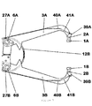
Figure 7 : Representation of a transmission mechanism of angular movement to the end tips, for maintaining the parallelism of their clamping faces, using a configuration based on a flexible element in compression confined in its housing, with the following components:- 1A and 1B - End tip A and B, respectively;
- 2A and 2B - Axis of rotation of the end tip A and B, respectively;
- 3A and 3B - Jaw A and B, respectively;
- 6A and 6B - Axis of rotation of the jaw A and B, respectively;
- 12B - Device cylindrical body;
- 27A and 27B - Anchoring point, on the cylindrical body (12B), of the flexible element (40A and 40B), respectively;
- 39A and 39B - Anchoring point of the flexible element (40A and 40B) on the end tip (1A and 1B), respectively;
- 40A and 40B - Flexible element located in jaw (3A and 3B), respectively;
- 41A and 41B - Flexible element housing (40A and 40B).
-
Figure 8 : Representation of a navigation system for interaction with the graphical interface of the computer application, using a joystick-type button, with the following components:- 3A - Jaw A;
- 8 - On/off switch;
- 9A - Joystick-type navigation button;
- 12A - Device handle.
-
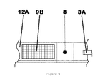
Figure 9 : Representation of a navigation system allowing interaction with the graphical interface of the computer application, using a touchscreen, with the following components:- 3A - Jaw A;
- 8 - On/off switch;
- 9B - Touchscreen;
- 12A - Device handle.
-
Figure 10 : representation of an electronic system, with the following components:- 8 - On/off switch;
- 9 - Device for remote interaction;
- 10A - Encoded sensing element;
- 10B - Reading sensing element;
- 13 - Power supply;
- 14 - Power charging jack;
- 15 - Measurement reset button;
- 17 - Trigger button for the time interval of the measurement protocol;
- 20 - Electronic system;
- 23 - Light indicator of the device power supply status;
- 24 - Light indicator for the on/off status of the electronic system (20);
- 25 - Light indicator of the on/off status of the device connection to the remote station;
- 42 - Remote station;
- 43 - Device display.
-
Figure 11 : Representation of a transmission system by toothed sectors which provides simultaneous opening of the jaws:- 3A and 3B - Jaw A and B, respectively;
- 6A and 6B - Axis of rotation of the jaw A and B,
- respectively;
- 12B - Device cylindrical body;
- 16 - Lever;
- 44A and 44B - Toothed sectors A and B, respectively.
-
Figure 12 : Representation of a transmission system by a four-bar hinged joint mechanism that allows the simultaneous opening of the jaws:- 3A and 3B - Jaw A and B, respectively;
- 6A and 6B - Axis of rotation of the jaw A and B, respectively;
- 12B - Device cylindrical body;
- 16 - Lever;
- 45 - Transmission bar;
- 46 - Axis of rotation of the transmission bar (45);
- 47 - Axis of rotation of the transmission bar (45);
- The developed apparatus uses working principles of a device for measuring skinfold thickness, integrating some additional elements for improving its accuracy and measuring range. It is a device for measuring skinfold thickness comprising one closed housing with a cylindrical part (12B) and a handle extension (12A), one structure with two jaws (3A and 3B) with hinged end tips (1A and 1B) and a lever (16).
- The device housing (12A and 12B) includes all the mechanical elements of force transmission from the constant force actuator (11) to the jaws (3A and 3B), the sensing element (10A and 10B), a power supply (13) as for example a battery, its power charging jack (14) and the electronic system (20).
- The cylindrical housing (12B) has a window (21) which permits a preferential embodiment for wireless communication with a remote station and the visualization of three light indicators which inform the user about the device on/off state, the on/off state of the communication with the remote station and the charge level of the power supply.
- The jaws (3A and 3B) have rotation axes (6A and 6B) and extension shields inside the cylindrical housing (12B). The jaws are manipulated using the handle (12A) and the lever (16), jaw closure being controlled by one transmission chain connected at the other end to the constant force actuator (11). The constant force actuator (11) installed in the device housing handle (12A), has the main function of imposing a constant pressure on the contact faces of the end tips (1A and 1B) with the skinfold under measurement. Additionally it ensures the return movement of the jaws (3A and 3B) during closure, while also eliminating mechanical backlash along the transmission chain.
- The constant force actuator (11) applies the force to the jaw (3B) by means, for example, of one inextensible cable (7) in contact with one cam (4), attached to the jaw (3B). Both jaws (3A and 3B) are interconnected by mechanical elements (5A and 5B) that accomplish their simultaneous opening.
- The increase of the maximum opening distance between end tips (1A and 1B) can be achieved by enlarging the length of the jaws (3A and 3B). This consideration could be explored for this and other devices in the market. Such solution has the inconvenient of implying an increase in structural robustness, size and weight and in addition it also requires a constant force actuator of higher intensity, which demands higher user hand grip strength.
- The increase of the maximum opening distance between end tips (1A and 1B) can also be achieved by providing the jaws (3A and 3B) with a larger angular opening. That is possible in this device, because it incorporates a rotating end tip (1A and 1B) mechanism which ensures the parallelism between their contact faces. Moreover the geometry of the jaws (3A and 3B) hinges minimizes the movement for accommodation of the position of the end tips (1A and 1B) by means of a large centre distance of the jaws (3A and 3B) hinges. Due to this the variation of the length of the force arm is minimized and the maximum value of the said length occurs at an intermediate point between the maximum aperture and total closure of the jaws (3A and 3B). The inclusion of the cam (4) whose profile compensates for variations in the length of the arm of the skinfold reaction force to the jaws (3A and 3B), guarantees the application of a constant force by the clamping surface of the end tips (1A and 1B) to the skinfold under measurement. With the complete stroke of the lever (16) it is possible to perform a skinfold thickness measurement of 110 mm, or higher.
- This value is considerably higher than that achieved by devices available in the market whose maximum skinfold thickness measurement does not usually exceed 80 mm.
- The end tips (1A and 1B) are hinged at the rotation axes (2A and 2B) in the extremities of the jaws (3A and 3B), respectively, keeping their clamping surfaces parallel to each other. The said parallelism is achieved by a movement transmission mechanism, it is independent of the opening angle of the jaws(3A and 3B) and it provides a constant uniform pressure on the whole contact area between the end tip clamping surfaces and the skinfold. In contrast to this, skinfold callipers available in the market either have end tips rigidly linked to the jaws or they do not have any parallelism control mechanism. When the end tips are rigidly linked to the jaws, they will not remain parallel to each other, and so the pressure applied to the skinfold is not uniform.
- End tips with free rotation and without any mechanism for enforcing parallelism are not able to correctly control the positioning of the clamping surfaces of the end tips. Consequently they do not comply with the established protocol that prescribes a uniformly distributed pressure of 10 gf/mm2. The movement transmission mechanism for keeping the said parallelism is based on the following systems: one parallelogram shaped mechanism with bars in tension and/or compression; one inextensible cable mechanism kept under tension by the action of an elastic element and one flexible element mechanism confined in its housing.
- The measurement of the distance between the clamping surface of the end tips (1A) and (1B) is performed by a sensing element (10A and 10B) integrated in the transmission chain between the constant force actuator (11) and the jaws (3A and 3B). The actuation of the sensing element (10A and 10B) is achieved through a displacement multiplication mechanism consisting in the elements (5B) and (19), which increases the resolution of the measurement of the distance between the end tip faces, for any given resolution of the encoder (10A and 10B). The backlash of the said multiplication mechanism (5B and 19) is eliminated by a spiral spring (18).
- In the lever (16), connected to the driving jaw (3B), and positioned at the operator index finger level, is located the button (17) for triggering the time interval according to the protocol for the skinfold clamping procedure and another button (15) is located, for example, at the lever (16) tail end for resetting the measurement to the zero value. In the concavity between the cylindrical housing (12B) and the handle (12A) there is the device on/off button (8) and a navigation system (9) which permits remote interaction with the graphical interface of the software application. The said system is based on a navigation button (9) or a touchscreen (9B). These four command elements are in the device symmetry plane, which, in conjunction with the global device configuration, makes its handling independent of the dominant hand of the operator. In a solution for autonomous use of the device it is necessary to have a display (43) for data visualization, which may have navigation functionality if it is of tactile type (9B).
- The constant force actuator (11) is based on an elastic element of constant force (11D). The said actuator multiplies the force of the elastic element of constant force (11D) by use of the said element with both ends winded on drums (11C1) and (11C2), supported by bearings (11B1) and (11B2) whose internal races are linked to the rotation axes (11E1) and (11E2), respectively. The force is conveyed to the transmission chain by a crescent shaped saddle (11A) on which the constant force elastic element (11D) rests.
- The extremity of the handle (12A) houses the power supply (13) with the respective power charging jack (14).
- The electronic system (20) in its distinct configurations can be composed by one power supply charging system, one signal conditioning system, one dedicated microcontroller, one display for data presentation (43) and one wireless communication system. It is responsible for the management of the whole device: it receives the operator commands through the buttons (8), (15), (17) and either from the navigation button (9A) or the touchscreen (9B), power supply level information, wireless communication data and sensing element data (10B). In accordance it controls the information supplied to the operator through the light indicators (23), (24) and (25), through the display (43) for data presentation and it is responsible for establishing the communication with the software application residing in the remote station.
- The information conveyed by the navigation button (9A) or by the touchscreen (9B) can be transmitted to the remote communication station to remotely operate the graphical interface of the software application. This functionality can be seen as complementary to the use of input devices directly connected to the remote communication station, such as: keyboard, mouse and tactile screen. This is intended to expedite the measurement procedures, reducing the time waste resulting from the recurring access to the peripherals of the remote communication station for triggering the computer application commands.
- The device ergonomic configuration offers considerable free lateral areas (22) on the jaws (3A and 3B), on the cylindrical housing (12B) and on the handle (12A), which are appropriate for displaying advertising elements.
- By pressing button (8) the electronic system (20) is activated and this state is signalled by the light indicator (24). The electronic system (20) presents data for interaction with the operator through the display device and can establish contact through its wireless communication system with the remote station, which will be signalled by the flashing of the light indicator (25). The battery charge level can be visualized through the indicator (23). Insufficient charge level is reported to the computational application.
- For recharging the device battery a compatible external power supply system is simply plugged to the charging jack (14). The battery charge level evolution is monitored by the evolution of the light indicator (23).
- By acting upon the button (15) the zero thickness value is set.
- When the operator moves the lever (16) towards the handle (12A) the button (17) remains pressed during the opening of the jaw (3B) which rotates about the axis (6B). This movement is transmitted to the mechanical part (5B) which in turn causes the simultaneous opening of the jaw (3A) that rotates around the axis (6A), while also pulling the inextensible cable (7) wound on the cam (4) which leads to a larger deflection of the constant force actuator (11). The said actuator, through the crescent shaped saddle (11A), transmits a constant opposing force to the kinematic chain. The movement of the mechanical part (5B) also leads to the actuation of the sensing element by means of a multiplication mechanism (5B and 19).
- The release of the force on the lever (16) permits the adjustment of the clamping surface of the end tips (1A and 1B) to the skinfold under measurement. The pressure exerted by the tips on the skinfold comes exclusively from the constant force actuator (11), transmitted by the kinematic chain. At completion of the force release on the lever (16) and with the skinfold under the pressure of the end tips (1A and 1B), the start of the time interval defined in the protocol is triggered by releasing the pressure on button (17).
- In the course of the movement of the jaws (3A and 3B), the contact surfaces of the end tips (1A and 1B) to the skinfold remain parallel to each other through the action of a parallel displacement mechanism of the end tips (1A and 1B).
- The skinfold thickness is measured by the distance between the contact surface of the end tips (1A and 1B), this information being transmitted to the encoded sensing element (10A) through the kinematic chain (1B, 3B, 5B and 19). The sensing reading element (10B) transmits the reading information to the dedicated microcontroller. After being processed by the dedicated microcontroller, all the information concerning the measurement is transmitted by the display (43). This information can be transmitted by wireless communication to the computer application in the remote station. The interaction with the computer application can be made using the navigation button (9A) or the touchscreen (9B). The command conveyed by the release of button (17) for starting the protocol time interval is processed by the dedicated microcontroller, triggering a real time counting of the protocol time interval, whose beginning and end information is presented on the display (43) and transmitted to the computer application by wireless communication.
- For a better understanding of the invention some examples are given which represent preferential embodiments of the invention but are not meant to limit the scope of this invention.
- Example 1 referring to
figure 3 : this constant force actuator mechanism is located in the device handle (12A) and comprises one crescent shaped saddle (11A), two drums (11C1) and (12C2), two bearings (11B1) and (11B2), two rotation axes (11E1) and (11E2) and one constant force spring (11D). - The constant force actuator (11) is based on a constant force spring (11D). It doubles the force of the spring (11D) by coiling both its ends over drums (11C1) and (11C2), supported by bearings (11B1) and (11B2) whose inner races are connected to the axes of rotation (11E1) and (11E2), respectively. The natural tendency of the spring is to wrap around the drums (11C1) and (11C2) thus exerting a tensile force at the end of the coupling. This force is conveyed to the transmission chain through a crescent shaped saddle (11A) on which rests the elastic element of constant force (11D), the saddle being pulled by the inextensible cable (7).
- The use of two overlapping springs of constant force (11D), i.e., the placement of two overlapping constant force springs, enables the doubling of the strength of the constant force actuator. In case a greater tensile force is needed, the number of overlapping springs can be augmented in order to increase the force/size ratio.
- Example 2 referring to
figure 4 : this mechanism is present in both jaws and equally applied. It consists of a primary parallelogram and a secondary parallelogram. - The primary parallelogram consists of two pairs of parallel line segments: the first pair is formed by the line segment between the axes of rotation (27A) and (31A) and the line segment between the axes of rotation (6A) and (30A); the second pair is formed by the line segment between the axes of rotation (27A) and (6A) and the line segment between the axes of rotation (31A) and (30A).
- The secondary parallelogram is composed by two pairs of parallel line segments: the first is formed by the line segment between the axes of rotation (32A) and (33A) and the line segment between the axes of rotation (30A) and (2A); the second is formed by the line segment between the axes of rotation (32A) and (30A) and the line segment between the axes of rotation (33A) and (2A).
- These parallelograms are interconnected by the coupling element (28A) that rotates around the axis of rotation (30A) in conjunction with the jaw (3A).
- In the parallelograms listed above, the axes (27A) and (6A) are fixed to the device body, the axes (30A) and (2A) are fixed to the jaw (3A), while the remaining axes (31A), (32A) and (33A) are floating and can move relative to the device housing (12B) and the jaw (3A).
- The mechanism installed in the jaw (3B) is identical to that described previously, changing the reference from A to B, with the exception of that of the device housing (12B).
- During the movement of the jaw (3A) and due to the fact that the sides of the parallelograms are materialized by rigid bars (26A) and (29A), the side of the primary parallelogram between the axes (27A) and (6A) remains stationary in relation to device housing (12B). This implies that the primary parallelogram side between the axes (30A) and (31A) is forced to remain parallel to the line segment between the axes (27A) and (6A), following the movement of the jaw (3A). Since the secondary parallelogram side between the axes (30A) and (32A) is defined in the coupling element (28A), on which is also defined the side of the primary parallelogram between the axes (30A) and (31A), the relative position of these two segments remains unchanged throughout the movement of the jaw (3A). Thus, the secondary parallelogram side between the axes (2a) and (33A) is forced to maintain its angular position relative to the side between the axes (27A) and (6A) of the primary parallelogram. The end tip face (1A) and the secondary parallelogram side between the axes of rotation (2A) and (33A) are defined in the same part, the end tip (1A), forcing the end tip face to keep its angular position in relation to the device housing (12B). For the mechanism located on the jaw (3B) its operation is analogous to that just described for the jaw (3A).
- As a result of this operation, the faces of the end tips (1A) and (1B) remain parallel to each other during the movement of the jaws (3A and 3B), and only have translation movement relative to the body of the device.
- Example 3 referring to
figure 5 : the description of the mechanism pertaining to this example is similar to that of the mechanism of example 2. The replacement of the elements (26A) and (29A) by inextensible cables (34A) and (35A) requires the introduction of an elastic element (36A) for keeping these two inextensible cables always in tension whatever the opening of the jaws (3A and 3B). - Thus, the conclusion of example 2 still holds regarding the end tip faces (1A and 1B) remaining parallel during the movement of the jaws (3A and 3B).
- The mechanism installed in the jaw (3B) is identical to that described previously, changing the reference from A to B.
- It should be noted that either one of the inextensible cables (34A) and (35A) located in each of the jaws (3A) and (3B), can be replaced by a rigid bar.
- Example 4 referring to
figure 6 : the length of the path between the anchoring points (27A) and (39A), established by the inextensible cable (37A) pulled tight by the action of the elastic element (38A), will remain constant whatever the jaw (3A) angle. Due to the equal length of the line segment between the axis (6A) and the anchoring point (27A) and the one between the axis (2A) and the anchoring point (39A) and given that the anchoring point (27A) is fixed to the device housing (12B), the faces of the end tips (1A) and (1B) remain parallel to each other during the movement of the jaws (3A and 3B), and only have translation movement relative to the device housing. - The mechanism installed in the jaw (3B) is identical to that described previously, changing the reference from A to B, with the exception of that of the device housing (12B).
- Example 5 referring to
figure 7 : the length of the path e between the anchoring points (27A) and (39A) established through a flexible element (40A) confined in its housing (41A), remains constant whatever the jaw (3A) angle. The flexible element (40A) works in compression and is confined in its housing (41A) in jaw (3A), with sliding clearance. Due to the equal length of the line segment between the axis (6A) and the anchoring point (27A) and the one between the axis (2A) and the anchoring point (39A) and given that the anchoring point (27A) is fixed to the device housing (12B), the faces of the end tips (1A) and (1B) remain parallel to each other during the movement of the jaws (3A and 3B), and only have translation movement relative to the device housing. - The mechanism installed in the jaw (3B) is identical to that described previously, changing the reference from A to B, with the exception of that of the device housing (12B).
- Example 6 referring to
figure 8 : the joystick-type navigation button (9A) triggers five distinct command actions on the software application cursor, allowing the operator to navigate the graphical interface. There are four steering actions and the fifth is for selection confirmation. - Example 7 referring to
figure 9 : the touchscreen (9B) triggers directional movements of the software application cursor, as a result of operator sliding actions on its surface. The confirmation of the selection is achieved by a touch on the touchscreen. - Example 8 referring to
figure 11 : the mechanism for simultaneous opening of the jaws (3A and 3B) is located inside the device housing (12B) and comprises two toothed sectors (44A and 44B) with equal pitch circle attached to the jaws (3A and 3B) and with rotation axes (6A and 6B), respectively. The rotation imposed on the sector (44B) by the action of the lever (16), transmits the motion to the toothed sector (44A) leading to the simultaneous opening of the two jaws (3A and 3B) and with equal amplitude. - Example 9 referring to
figure 12 : this mechanism for simultaneous opening of the jaws (3A and 3B) is located inside the device housing (12B) and consists of a hinged four-bar mechanism embodied by: a line segment between the axes (6A) and (47), a line segment between the axes (6B) and (46), a transmission bar (45) articulated between the axes (46) and (47) attached to the jaws (3A and 3B) and a bar materialized by the device housing (12B) between the axes (6A) and (6B). - The rotation of the lever (16) leads to the rotation of the segment between the axes (46) and (6B) around the axis (6B), which in turn forces the displacement of the transmission bar (45), causing the rotation of the segment lying between the axes (47) and (6A) around the axis (6A) and the consequent rotation of the jaw (3A) with an amplitude equal to that of the jaw (3B). These rotations have the same amplitude since the line segments included between the pairs of axes (6A and 47) and (6B and 46) are of equal length.
- The following claims additionally represent preferential embodiments of the present invention.
Claims (11)
- Device for measuring the thickness of skin folds that comprises:- a device housing (12B), preferably of closed cylindrical shape, with an extension for handling (12A);- a structure with two jaws (3A and 3B) with hinged end tips (1A and 1B) mechanically oriented and one lever (16);- a constant force actuator mechanism (11);- a cam (4) with a profile that compensates the variation of the force arm length in the jaws (3A and 3B) and which provides the transmission of the force generated by the said constant force actuator (11).
- Device for measuring the thickness of skin folds as defined in the previous claim, in which the said constant force actuator (11) includes:One crescent shaped saddle (11A) which supports at least one constant force elastic element (11 D), two drums (11C1) and (11C2), two bearings (11B1) and (11B2), two rotation axes (11E1) and (11E2).
- Device for measuring the thickness of skin folds in accordance with any of the previous claims, in which the jaws (3A and 3B) are hinged on two rotation axes (6A and 6B) whose centre distance is large enough to correspond to about one half of the maximum opening of the jaws (3A and 3B).
- Device for measuring the thickness of skin folds as defined in any of the previous claims, in which the end tips (1A and 1B) are hinged and mechanically oriented to keep the parallelism between their contact faces through a mechanism actuated by the opening/closing of the jaws (3A and 3B).
- Device for measuring the thickness of skin folds as defined in any of the previous claims, including a movement transmission mechanism to the end tips (1A and 1B) based on the following guidance systems: one mechanism of parallelograms configuration with tensile and/or compression bars; one inextensible cable mechanism under tension by elastic element action; one flexible element mechanism confined in its housing.
- Device for measuring the thickness of skin folds as defined in any of the previous claims, in which the elastic constant force element (11 D) is a spring.
- Device for measuring the thickness of skin folds as defined in any of the previous claims, that also includes a mechanism for multiplying the angular displacement of the jaws (3A and 3B) that increases the resolution of the measurement of the distance between the faces of the end tips (1A and 1B).
- Device for measuring the thickness of skin folds as defined in any of the previous claims, in which the housing (12A and 12B) accommodates all the mechanical elements for force transmission of the constant force actuator (11) to the jaws (3A and 3B), the sensing element (10A and 10B) and the electronic system (20).
- Device for measuring the thickness of skin folds as defined in any of the previous claims, that also includes an electronic system (20) consisting of one rechargeable power supply system, one signal conditioning system, one dedicated microcontroller and one system for wireless communication.
- Device for measuring the thickness of skin folds as defined in any of the previous claims, that also includes one window (21) that allows wireless communication with the remote station (42) and the visualization of light indicators for user information.
- Device for measuring the thickness of skin folds as defined in any of the previous claims, that includes one on/off switch, one display, one navigation system in the device symmetry plan, in order to make the handling of the device independent of the dominant hand of the operator.
Applications Claiming Priority (2)
| Application Number | Priority Date | Filing Date | Title |
|---|---|---|---|
| PT105187A PT105187B (en) | 2010-07-02 | 2010-07-02 | DEVICE FOR MEASURING THE THICKNESS SKIN THICKNESS |
| PCT/IB2010/055701 WO2012001467A1 (en) | 2010-07-02 | 2010-12-09 | Device for measuring the thickness of skin folds |
Publications (2)
| Publication Number | Publication Date |
|---|---|
| EP2589336A1 true EP2589336A1 (en) | 2013-05-08 |
| EP2589336B1 EP2589336B1 (en) | 2018-08-08 |
Family
ID=43858479
Family Applications (1)
| Application Number | Title | Priority Date | Filing Date |
|---|---|---|---|
| EP10809178.6A Active EP2589336B1 (en) | 2010-07-02 | 2010-12-09 | Device for measuring the thickness of skin folds |
Country Status (4)
| Country | Link |
|---|---|
| US (1) | US9198602B2 (en) |
| EP (1) | EP2589336B1 (en) |
| PT (1) | PT105187B (en) |
| WO (1) | WO2012001467A1 (en) |
Families Citing this family (8)
| Publication number | Priority date | Publication date | Assignee | Title |
|---|---|---|---|---|
| JP6055646B2 (en) * | 2012-02-10 | 2016-12-27 | 三菱樹脂株式会社 | Aliphatic polyester resin laminate sheet and plastic case for packaging container using the same |
| US20140063220A1 (en) | 2012-08-29 | 2014-03-06 | Ossur Hf | Method and Device for Ordering a Custom Orthopedic Device |
| US9182210B2 (en) * | 2012-08-29 | 2015-11-10 | Ossur Hf | Caliper for measurement of an object |
| CN105380653A (en) * | 2015-12-21 | 2016-03-09 | 华北理工大学 | Skinfold thickness gauge with depth measurement ruler |
| KR101771156B1 (en) * | 2016-06-16 | 2017-08-24 | 정한나 | Skin-fold caliper |
| DE102017117102B3 (en) | 2017-07-28 | 2019-01-24 | 2B1 Gmbh | Apparatus for measuring the thickness of a body skin fold under constant pressure for determining body fat percentage |
| DE202017104511U1 (en) | 2017-07-28 | 2017-08-07 | 2B1 Gmbh | Apparatus for measuring the thickness of a body skin fold under constant pressure for determining body fat percentage |
| CN211155735U (en) * | 2019-07-26 | 2020-08-04 | 德清量丰电子科技股份有限公司 | Fat detector |
Family Cites Families (10)
| Publication number | Priority date | Publication date | Assignee | Title |
|---|---|---|---|---|
| CH243735A (en) * | 1944-08-16 | 1946-07-31 | Ag Veterinaria | Device for measuring the thickness of the skin folds. |
| US3008239A (en) | 1960-05-16 | 1961-11-14 | Karl O Lange | Constant pressure calipers |
| US4127112A (en) * | 1977-04-06 | 1978-11-28 | American Hospital Supply Corp. | Skin fold caliper |
| US4201226A (en) * | 1977-07-26 | 1980-05-06 | Phillips Robert L | Combination instrument for taking biomechanical measurements |
| US4315372A (en) * | 1980-04-17 | 1982-02-16 | Fitness Motivation Institute Of America | Caliper for applying constant pressure to an object being measured |
| US5156161A (en) * | 1991-08-02 | 1992-10-20 | Lollar John A | Skinfold caliper for body fat measurement |
| EP0558194A1 (en) | 1992-02-25 | 1993-09-01 | Robert Edward Best | Measuring calliper |
| US6301799B1 (en) * | 2000-03-09 | 2001-10-16 | Charles Ho | Electronic fat gauge |
| US20060162178A1 (en) * | 2005-01-27 | 2006-07-27 | Freidin Philip M | System for wireless local display of measurement data from electronic measuring tools and gauges |
| EP2417416A4 (en) * | 2009-03-23 | 2013-04-03 | Iberius Llc | Improved hair measuring assembly and single use cartridge |
-
2010
- 2010-07-02 PT PT105187A patent/PT105187B/en active IP Right Grant
- 2010-12-09 WO PCT/IB2010/055701 patent/WO2012001467A1/en not_active Ceased
- 2010-12-09 US US13/807,658 patent/US9198602B2/en active Active
- 2010-12-09 EP EP10809178.6A patent/EP2589336B1/en active Active
Non-Patent Citations (1)
| Title |
|---|
| See references of WO2012001467A1 * |
Also Published As
| Publication number | Publication date |
|---|---|
| US9198602B2 (en) | 2015-12-01 |
| US20130123668A1 (en) | 2013-05-16 |
| PT105187B (en) | 2013-10-02 |
| WO2012001467A1 (en) | 2012-01-05 |
| EP2589336B1 (en) | 2018-08-08 |
| PT105187A (en) | 2012-01-02 |
Similar Documents
| Publication | Publication Date | Title |
|---|---|---|
| EP2589336B1 (en) | Device for measuring the thickness of skin folds | |
| US11779419B2 (en) | Autonomous correction of alignment error in a master-slave robotic system | |
| US10071485B2 (en) | Hand controller device | |
| EP2706944B1 (en) | Surgical instrument device | |
| CN103889358A (en) | Surgical Support Device | |
| CN107847105B (en) | Control unit for flexible endoscope | |
| US12502767B2 (en) | Master manipulator control apparatuses and robots including the same | |
| JPWO2017130562A1 (en) | Gripping force sense presentation device and stylus type force sense presentation device | |
| EP2116174A1 (en) | Endoscope device | |
| US8844376B2 (en) | Multi-degree of freedom transducer | |
| CN104880135A (en) | Wheel Assembly For Moving Caliper Jaw With Repeatable Force | |
| CN104394792A (en) | Surgical Support Device | |
| KR101801302B1 (en) | Robot hand and surface robot system using of the same for working | |
| US12279920B2 (en) | Configurable counterbalance mechanism | |
| WO2019093020A1 (en) | Medical manipulation unit | |
| JP2009300352A (en) | Length measuring apparatus | |
| CN113752236A (en) | Mechanical arm teaching device, calibration rod and method | |
| KR20140132113A (en) | Method for compensating backlash and method for making backlash compensation value calculating formular | |
| KR101875016B1 (en) | Remote control device | |
| CN114176782A (en) | Hand instruction sensing device of surgical operation robot | |
| KR100681768B1 (en) | Compact Haptic Device | |
| JPH1133939A (en) | Master manipulator | |
| US20260124759A1 (en) | Master manipulator control apparatuses and robots including the same | |
| HK40119610A (en) | Master device and surgical robot | |
| KR102225106B1 (en) | Master apparatus for teleoperation |
Legal Events
| Date | Code | Title | Description |
|---|---|---|---|
| PUAI | Public reference made under article 153(3) epc to a published international application that has entered the european phase |
Free format text: ORIGINAL CODE: 0009012 |
|
| 17P | Request for examination filed |
Effective date: 20130111 |
|
| AK | Designated contracting states |
Kind code of ref document: A1 Designated state(s): AL AT BE BG CH CY CZ DE DK EE ES FI FR GB GR HR HU IE IS IT LI LT LU LV MC MK MT NL NO PL PT RO RS SE SI SK SM TR |
|
| RIN1 | Information on inventor provided before grant (corrected) |
Inventor name: DE CASTRO CHOUSAL, MARIA DE FATIMA Inventor name: BRAGA VALENTE DE ALMEIDA RESTIVO, MARIA TERESA Inventor name: DE SERPA PINTO FREITAS DO AMARAL, TERESA MARIA Inventor name: FAUSTINO ANDRADE, TIAGO Inventor name: SOUSA MOREIRA DA SILVA, CARLOS MANUEL Inventor name: RODRIGUES QUINTAS, MANUEL |
|
| RIN1 | Information on inventor provided before grant (corrected) |
Inventor name: BRAGA VALENTE DE ALMEIDA RESTIVO, MARIA TERESA Inventor name: SOUSA MOREIRA DA SILVA, CARLOS MANUEL Inventor name: RODRIGUES QUINTAS, MANUEL Inventor name: DE SERPA PINTO FREITAS DO AMARAL, TERESA MARIA Inventor name: FAUSTINO ANDRADE, TIAGO Inventor name: DE CASTRO CHOUSAL, MARIA DE FATIMA |
|
| RIN1 | Information on inventor provided before grant (corrected) |
Inventor name: DE CASTRO CHOUSAL, MARIA DE FATIMA Inventor name: BRAGA VALENTE DE ALMEIDA RESTIVO, MARIA TERESA Inventor name: FAUSTINO ANDRADE, TIAGO Inventor name: DE SERPA PINTO FREITAS DO AMARAL, TERESA MARIA Inventor name: RODRIGUES QUINTAS, MANUEL Inventor name: SOUSA MOREIRA DA SILVA, CARLOS MANUEL |
|
| DAX | Request for extension of the european patent (deleted) | ||
| RIC1 | Information provided on ipc code assigned before grant |
Ipc: A61B 5/107 20060101AFI20180215BHEP Ipc: G01B 3/16 20060101ALI20180215BHEP |
|
| GRAP | Despatch of communication of intention to grant a patent |
Free format text: ORIGINAL CODE: EPIDOSNIGR1 |
|
| INTG | Intention to grant announced |
Effective date: 20180320 |
|
| GRAS | Grant fee paid |
Free format text: ORIGINAL CODE: EPIDOSNIGR3 |
|
| GRAA | (expected) grant |
Free format text: ORIGINAL CODE: 0009210 |
|
| AK | Designated contracting states |
Kind code of ref document: B1 Designated state(s): AL AT BE BG CH CY CZ DE DK EE ES FI FR GB GR HR HU IE IS IT LI LT LU LV MC MK MT NL NO PL PT RO RS SE SI SK SM TR |
|
| REG | Reference to a national code |
Ref country code: GB Ref legal event code: FG4D |
|
| REG | Reference to a national code |
Ref country code: CH Ref legal event code: EP Ref country code: AT Ref legal event code: REF Ref document number: 1026052 Country of ref document: AT Kind code of ref document: T Effective date: 20180815 |
|
| REG | Reference to a national code |
Ref country code: IE Ref legal event code: FG4D |
|
| REG | Reference to a national code |
Ref country code: DE Ref legal event code: R096 Ref document number: 602010052615 Country of ref document: DE |
|
| REG | Reference to a national code |
Ref country code: CH Ref legal event code: NV Representative=s name: OFFICE ERNEST T. FREYLINGER S.A., CH |
|
| REG | Reference to a national code |
Ref country code: NL Ref legal event code: MP Effective date: 20180808 |
|
| REG | Reference to a national code |
Ref country code: LT Ref legal event code: MG4D |
|
| REG | Reference to a national code |
Ref country code: AT Ref legal event code: MK05 Ref document number: 1026052 Country of ref document: AT Kind code of ref document: T Effective date: 20180808 |
|
| PG25 | Lapsed in a contracting state [announced via postgrant information from national office to epo] |
Ref country code: FI Free format text: LAPSE BECAUSE OF FAILURE TO SUBMIT A TRANSLATION OF THE DESCRIPTION OR TO PAY THE FEE WITHIN THE PRESCRIBED TIME-LIMIT Effective date: 20180808 Ref country code: SE Free format text: LAPSE BECAUSE OF FAILURE TO SUBMIT A TRANSLATION OF THE DESCRIPTION OR TO PAY THE FEE WITHIN THE PRESCRIBED TIME-LIMIT Effective date: 20180808 Ref country code: IS Free format text: LAPSE BECAUSE OF FAILURE TO SUBMIT A TRANSLATION OF THE DESCRIPTION OR TO PAY THE FEE WITHIN THE PRESCRIBED TIME-LIMIT Effective date: 20181208 Ref country code: RS Free format text: LAPSE BECAUSE OF FAILURE TO SUBMIT A TRANSLATION OF THE DESCRIPTION OR TO PAY THE FEE WITHIN THE PRESCRIBED TIME-LIMIT Effective date: 20180808 Ref country code: PL Free format text: LAPSE BECAUSE OF FAILURE TO SUBMIT A TRANSLATION OF THE DESCRIPTION OR TO PAY THE FEE WITHIN THE PRESCRIBED TIME-LIMIT Effective date: 20180808 Ref country code: LT Free format text: LAPSE BECAUSE OF FAILURE TO SUBMIT A TRANSLATION OF THE DESCRIPTION OR TO PAY THE FEE WITHIN THE PRESCRIBED TIME-LIMIT Effective date: 20180808 Ref country code: NL Free format text: LAPSE BECAUSE OF FAILURE TO SUBMIT A TRANSLATION OF THE DESCRIPTION OR TO PAY THE FEE WITHIN THE PRESCRIBED TIME-LIMIT Effective date: 20180808 Ref country code: AT Free format text: LAPSE BECAUSE OF FAILURE TO SUBMIT A TRANSLATION OF THE DESCRIPTION OR TO PAY THE FEE WITHIN THE PRESCRIBED TIME-LIMIT Effective date: 20180808 Ref country code: NO Free format text: LAPSE BECAUSE OF FAILURE TO SUBMIT A TRANSLATION OF THE DESCRIPTION OR TO PAY THE FEE WITHIN THE PRESCRIBED TIME-LIMIT Effective date: 20181108 Ref country code: GR Free format text: LAPSE BECAUSE OF FAILURE TO SUBMIT A TRANSLATION OF THE DESCRIPTION OR TO PAY THE FEE WITHIN THE PRESCRIBED TIME-LIMIT Effective date: 20181109 Ref country code: BG Free format text: LAPSE BECAUSE OF FAILURE TO SUBMIT A TRANSLATION OF THE DESCRIPTION OR TO PAY THE FEE WITHIN THE PRESCRIBED TIME-LIMIT Effective date: 20181108 |
|
| PG25 | Lapsed in a contracting state [announced via postgrant information from national office to epo] |
Ref country code: AL Free format text: LAPSE BECAUSE OF FAILURE TO SUBMIT A TRANSLATION OF THE DESCRIPTION OR TO PAY THE FEE WITHIN THE PRESCRIBED TIME-LIMIT Effective date: 20180808 Ref country code: HR Free format text: LAPSE BECAUSE OF FAILURE TO SUBMIT A TRANSLATION OF THE DESCRIPTION OR TO PAY THE FEE WITHIN THE PRESCRIBED TIME-LIMIT Effective date: 20180808 Ref country code: LV Free format text: LAPSE BECAUSE OF FAILURE TO SUBMIT A TRANSLATION OF THE DESCRIPTION OR TO PAY THE FEE WITHIN THE PRESCRIBED TIME-LIMIT Effective date: 20180808 |
|
| PG25 | Lapsed in a contracting state [announced via postgrant information from national office to epo] |
Ref country code: EE Free format text: LAPSE BECAUSE OF FAILURE TO SUBMIT A TRANSLATION OF THE DESCRIPTION OR TO PAY THE FEE WITHIN THE PRESCRIBED TIME-LIMIT Effective date: 20180808 Ref country code: ES Free format text: LAPSE BECAUSE OF FAILURE TO SUBMIT A TRANSLATION OF THE DESCRIPTION OR TO PAY THE FEE WITHIN THE PRESCRIBED TIME-LIMIT Effective date: 20180808 Ref country code: CZ Free format text: LAPSE BECAUSE OF FAILURE TO SUBMIT A TRANSLATION OF THE DESCRIPTION OR TO PAY THE FEE WITHIN THE PRESCRIBED TIME-LIMIT Effective date: 20180808 Ref country code: IT Free format text: LAPSE BECAUSE OF FAILURE TO SUBMIT A TRANSLATION OF THE DESCRIPTION OR TO PAY THE FEE WITHIN THE PRESCRIBED TIME-LIMIT Effective date: 20180808 Ref country code: RO Free format text: LAPSE BECAUSE OF FAILURE TO SUBMIT A TRANSLATION OF THE DESCRIPTION OR TO PAY THE FEE WITHIN THE PRESCRIBED TIME-LIMIT Effective date: 20180808 |
|
| REG | Reference to a national code |
Ref country code: DE Ref legal event code: R097 Ref document number: 602010052615 Country of ref document: DE |
|
| PG25 | Lapsed in a contracting state [announced via postgrant information from national office to epo] |
Ref country code: SM Free format text: LAPSE BECAUSE OF FAILURE TO SUBMIT A TRANSLATION OF THE DESCRIPTION OR TO PAY THE FEE WITHIN THE PRESCRIBED TIME-LIMIT Effective date: 20180808 Ref country code: DK Free format text: LAPSE BECAUSE OF FAILURE TO SUBMIT A TRANSLATION OF THE DESCRIPTION OR TO PAY THE FEE WITHIN THE PRESCRIBED TIME-LIMIT Effective date: 20180808 Ref country code: SK Free format text: LAPSE BECAUSE OF FAILURE TO SUBMIT A TRANSLATION OF THE DESCRIPTION OR TO PAY THE FEE WITHIN THE PRESCRIBED TIME-LIMIT Effective date: 20180808 |
|
| PLBE | No opposition filed within time limit |
Free format text: ORIGINAL CODE: 0009261 |
|
| STAA | Information on the status of an ep patent application or granted ep patent |
Free format text: STATUS: NO OPPOSITION FILED WITHIN TIME LIMIT |
|
| 26N | No opposition filed |
Effective date: 20190509 |
|
| REG | Reference to a national code |
Ref country code: CH Ref legal event code: PL |
|
| PG25 | Lapsed in a contracting state [announced via postgrant information from national office to epo] |
Ref country code: SI Free format text: LAPSE BECAUSE OF FAILURE TO SUBMIT A TRANSLATION OF THE DESCRIPTION OR TO PAY THE FEE WITHIN THE PRESCRIBED TIME-LIMIT Effective date: 20180808 Ref country code: LU Free format text: LAPSE BECAUSE OF NON-PAYMENT OF DUE FEES Effective date: 20181209 Ref country code: MC Free format text: LAPSE BECAUSE OF FAILURE TO SUBMIT A TRANSLATION OF THE DESCRIPTION OR TO PAY THE FEE WITHIN THE PRESCRIBED TIME-LIMIT Effective date: 20180808 |
|
| REG | Reference to a national code |
Ref country code: IE Ref legal event code: MM4A |
|
| REG | Reference to a national code |
Ref country code: BE Ref legal event code: MM Effective date: 20181231 |
|
| PG25 | Lapsed in a contracting state [announced via postgrant information from national office to epo] |
Ref country code: IE Free format text: LAPSE BECAUSE OF NON-PAYMENT OF DUE FEES Effective date: 20181209 |
|
| PG25 | Lapsed in a contracting state [announced via postgrant information from national office to epo] |
Ref country code: BE Free format text: LAPSE BECAUSE OF NON-PAYMENT OF DUE FEES Effective date: 20181231 |
|
| PG25 | Lapsed in a contracting state [announced via postgrant information from national office to epo] |
Ref country code: CH Free format text: LAPSE BECAUSE OF NON-PAYMENT OF DUE FEES Effective date: 20181231 Ref country code: LI Free format text: LAPSE BECAUSE OF NON-PAYMENT OF DUE FEES Effective date: 20181231 |
|
| PG25 | Lapsed in a contracting state [announced via postgrant information from national office to epo] |
Ref country code: MT Free format text: LAPSE BECAUSE OF NON-PAYMENT OF DUE FEES Effective date: 20181209 |
|
| PG25 | Lapsed in a contracting state [announced via postgrant information from national office to epo] |
Ref country code: TR Free format text: LAPSE BECAUSE OF FAILURE TO SUBMIT A TRANSLATION OF THE DESCRIPTION OR TO PAY THE FEE WITHIN THE PRESCRIBED TIME-LIMIT Effective date: 20180808 |
|
| PG25 | Lapsed in a contracting state [announced via postgrant information from national office to epo] |
Ref country code: PT Free format text: LAPSE BECAUSE OF FAILURE TO SUBMIT A TRANSLATION OF THE DESCRIPTION OR TO PAY THE FEE WITHIN THE PRESCRIBED TIME-LIMIT Effective date: 20180808 |
|
| PG25 | Lapsed in a contracting state [announced via postgrant information from national office to epo] |
Ref country code: MK Free format text: LAPSE BECAUSE OF NON-PAYMENT OF DUE FEES Effective date: 20180808 Ref country code: HU Free format text: LAPSE BECAUSE OF FAILURE TO SUBMIT A TRANSLATION OF THE DESCRIPTION OR TO PAY THE FEE WITHIN THE PRESCRIBED TIME-LIMIT; INVALID AB INITIO Effective date: 20101209 Ref country code: CY Free format text: LAPSE BECAUSE OF FAILURE TO SUBMIT A TRANSLATION OF THE DESCRIPTION OR TO PAY THE FEE WITHIN THE PRESCRIBED TIME-LIMIT Effective date: 20180808 |
|
| PGFP | Annual fee paid to national office [announced via postgrant information from national office to epo] |
Ref country code: FR Payment date: 20231122 Year of fee payment: 14 Ref country code: DE Payment date: 20231114 Year of fee payment: 14 |
|
| REG | Reference to a national code |
Ref country code: DE Ref legal event code: R119 Ref document number: 602010052615 Country of ref document: DE |
|
| REG | Reference to a national code |
Ref country code: GB Ref legal event code: 732E Free format text: REGISTERED BETWEEN 20250619 AND 20250625 |
|
| PG25 | Lapsed in a contracting state [announced via postgrant information from national office to epo] |
Ref country code: DE Free format text: LAPSE BECAUSE OF NON-PAYMENT OF DUE FEES Effective date: 20250701 |
|
| PG25 | Lapsed in a contracting state [announced via postgrant information from national office to epo] |
Ref country code: FR Free format text: LAPSE BECAUSE OF NON-PAYMENT OF DUE FEES Effective date: 20241231 |
|
| PGFP | Annual fee paid to national office [announced via postgrant information from national office to epo] |
Ref country code: GB Payment date: 20251001 Year of fee payment: 16 |