EP2587820A2 - Volumetric display - Google Patents
Volumetric display Download PDFInfo
- Publication number
- EP2587820A2 EP2587820A2 EP12187415.0A EP12187415A EP2587820A2 EP 2587820 A2 EP2587820 A2 EP 2587820A2 EP 12187415 A EP12187415 A EP 12187415A EP 2587820 A2 EP2587820 A2 EP 2587820A2
- Authority
- EP
- European Patent Office
- Prior art keywords
- display
- volumetric
- flat panel
- location
- panel display
- Prior art date
- Legal status (The legal status is an assumption and is not a legal conclusion. Google has not performed a legal analysis and makes no representation as to the accuracy of the status listed.)
- Withdrawn
Links
- 229920002261 Corn starch Polymers 0.000 claims description 2
- 239000008120 corn starch Substances 0.000 claims description 2
- 229940099112 cornstarch Drugs 0.000 claims description 2
- 239000004973 liquid crystal related substance Substances 0.000 claims description 2
- 239000000203 mixture Substances 0.000 claims description 2
- XLYOFNOQVPJJNP-UHFFFAOYSA-N water Substances O XLYOFNOQVPJJNP-UHFFFAOYSA-N 0.000 claims description 2
- 229920001621 AMOLED Polymers 0.000 description 2
- 239000011521 glass Substances 0.000 description 2
- 239000013078 crystal Substances 0.000 description 1
- 230000001419 dependent effect Effects 0.000 description 1
- 238000009792 diffusion process Methods 0.000 description 1
- 238000010329 laser etching Methods 0.000 description 1
- 239000000463 material Substances 0.000 description 1
- 238000000034 method Methods 0.000 description 1
- 230000002688 persistence Effects 0.000 description 1
- 238000009987 spinning Methods 0.000 description 1
- 230000000007 visual effect Effects 0.000 description 1
Images
Classifications
-
- G—PHYSICS
- G02—OPTICS
- G02B—OPTICAL ELEMENTS, SYSTEMS OR APPARATUS
- G02B26/00—Optical devices or arrangements for the control of light using movable or deformable optical elements
- G02B26/004—Optical devices or arrangements for the control of light using movable or deformable optical elements based on a displacement or a deformation of a fluid
- G02B26/005—Optical devices or arrangements for the control of light using movable or deformable optical elements based on a displacement or a deformation of a fluid based on electrowetting
-
- H—ELECTRICITY
- H04—ELECTRIC COMMUNICATION TECHNIQUE
- H04N—PICTORIAL COMMUNICATION, e.g. TELEVISION
- H04N13/00—Stereoscopic video systems; Multi-view video systems; Details thereof
- H04N13/30—Image reproducers
- H04N13/388—Volumetric displays, i.e. systems where the image is built up from picture elements distributed through a volume
- H04N13/39—Volumetric displays, i.e. systems where the image is built up from picture elements distributed through a volume the picture elements emitting light at places where a pair of light beams intersect in a transparent material
Definitions
- This disclosure generally relates to volumetric displays, and more particularly relates to a volumetric display that uses a flat panel display to project light into a volumetric diffuser to form a true three dimensional image.
- a volumetric display for displaying three dimensional (3D) images.
- the volumetric display includes a flat panel display, a volumetric diffuser, and an array of electrowetting lenses.
- the flat panel display includes a two dimensional array of pixels individually operable to emit light.
- the volumetric diffuser is positioned proximate to the flat panel display and configured to define a display volume.
- the array of electrowetting lenses is interposed between the flat panel display and the volumetric diffuser. Each electrowetting lens is operable to direct light emitted by one or more of the pixels toward a location within the display volume such that the location is illuminated brighter than other locations within the display volume.
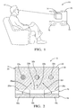
- Fig. 1 is perspective view of a person viewing a volumetric display in accordance with one embodiment
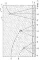
- Fig. 2 is a sectional side view of a volumetric display in accordance with one embodiment.
- Fig. 3 is a sectional side view of a volumetric display in accordance with one embodiment.
- Fig. 1 illustrates a non-limiting example of a volumetric display 10 for displaying three dimensional (3D) images.
- a volumetric display is a graphical display device that forms a 3D image in three actual physical dimensions, as opposed to a simulated 3D image on a planar display like a 3D television display that simulates depth through a number of different visual effects.
- a person 12 viewing the volumetric display 10 when displaying an image 14, for example an image of a cube as illustrated will be able to move about the volumetric display 10 and view the image 14 from different perspectives just as if the cube was actually present within the volumetric display 10.
- Fig. 2 illustrates a sectional side view of the volumetric display 10 that includes a flat panel display 16.
- the flat panel display 16 is formed by a two dimensional array of pixels.
- Fig. 2 illustrates pixels 18a, 18b, and 18c in a one dimensional array only for the purpose of explanation and not limitation.
- Suitable examples of devices that could be used as the flat panel display 16 include liquid crystal display (LCD) or a light emitting diode display (LED), such as suitably sized active matrix organic light emitting diode display (AMOLED) from the Samsung Corp.
- the size and resolution of the display is selected based on the performance desired for the volumetric display 10.
- each pixel 18a, 18b, 18c is, in general, individually operable to selectively emit light so an image from the flat panel display 16 can be presented by the volumetric display 10. It should be further appreciated that each pixel may include a red LED, a green LED, and a blue LED so light emitted by any particular pixel may exhibit any color.
- the volumetric display 10 also includes a volumetric diffuser 20 positioned proximate to the flat panel display 16 and configured to define a display volume 22.
- a volumetric diffuser is, in general, an object that diffuses light projected into the volumetric diffuser so that points or regions within the volumetric diffuser 20 are illuminated to a degree dependent on how much light is present at the point or region.
- the non-limiting example of the volumetric display 10 described herein was demonstrated using a volumetric diffuser that included a transparent container 24 formed of glass to define the display volume 22.
- the transparent container 24 was filled with a solution or mixture of food grade powdered cornstarch suspended in water.
- volumetric diffuser 20 such as AerogelTM available from BuyAerogel.com.
- AerogelTM available from BuyAerogel.com.
- Another suitable volumetric diffuser may be formed by laser etching a pattern of diffusion locations within a volume of glass.
- the volumetric display 10 also includes an array of electrowetting lenses 26 interposed between the flat panel display 16 and the volumetric diffuser 20.
- each electrowetting lens 28a, 28b, 28c is operable to direct light 30a, 30b, 30c emitted by one or more of the pixels toward a location 32a within the display volume 22 such that the location 32a is selectively illuminated brighter than other locations 32b, 32c within the display volume 22.
- a suitable example of an electrowetting lens is shown in United States Patent Number 7,352,512 to Hendriks et al. , titled VARIABLE FOCUS LENS, issued April 1, 2008.
- Fig. 3 further illustrates a non-limiting example of how light from various pixels 18a-i can be directed or focused by the array of electrowetting lenses 26 to combine at particular locations (e.g. locations 32a, 32d, 32e) to illuminate those locations to a greater degree of brightness than areas or locations surrounding those particular location.
- locations 32a, 32d, 32e e.g. locations 32a, 32d, 32e
- the light from tens or hundreds of pixels may be focused on a single location to brightly illuminate that location.
- the flat panel display 16 and the array of electrowetting lenses 26 may cooperate to simultaneously illuminate a location with light passing through a plurality of electrowetting lenses. By this, a particular location is simultaneously illuminated by many pixels.
- the flat panel display 16 and the array of electrowetting lenses 26 may cooperate to time-multiplexingly illuminate a location with light passing through a plurality of electrowetting lenses. By this method, the perceived persistence of light at a particular location when viewed by a person may be used so many different locations may be illuminated at various times by various pixels, but the light appears to combine to illuminate one location to greater degree than another.
- volumetric display 10 is provided.
- volumetric diffusor 20 to provide an illuminable location, and an array of electrowetting lenses 26 to direct light from the flat panel display 16 to the location, a true 3D display is provided without the complexity of spinning mirrors or other complications.
Landscapes
- Physics & Mathematics (AREA)
- Engineering & Computer Science (AREA)
- Multimedia (AREA)
- Signal Processing (AREA)
- General Physics & Mathematics (AREA)
- Optics & Photonics (AREA)
- Devices For Indicating Variable Information By Combining Individual Elements (AREA)
- Testing, Inspecting, Measuring Of Stereoscopic Televisions And Televisions (AREA)
- Illuminated Signs And Luminous Advertising (AREA)
Abstract
Description
- This disclosure generally relates to volumetric displays, and more particularly relates to a volumetric display that uses a flat panel display to project light into a volumetric diffuser to form a true three dimensional image.
- True three dimensional (3D) displays have been proposed that allow a person viewing the display to walk around the display and view an object being displayed from any angle just as if the object were actually present. However, many of these true 3D displays have complicated rotating mirrors or similar devices that add expense and reduce convenience.
- In accordance with one embodiment, a volumetric display for displaying three dimensional (3D) images is provided. The volumetric display includes a flat panel display, a volumetric diffuser, and an array of electrowetting lenses. The flat panel display includes a two dimensional array of pixels individually operable to emit light. The volumetric diffuser is positioned proximate to the flat panel display and configured to define a display volume. The array of electrowetting lenses is interposed between the flat panel display and the volumetric diffuser. Each electrowetting lens is operable to direct light emitted by one or more of the pixels toward a location within the display volume such that the location is illuminated brighter than other locations within the display volume.
- Further features and advantages will appear more clearly on a reading of the following detailed description of the preferred embodiment, which is given by way of non-limiting example only and with reference to the accompanying drawings.
- The present invention will now be described, by way of example with reference to the accompanying drawings, in which:
-
Fig. 1 is perspective view of a person viewing a volumetric display in accordance with one embodiment; -
Fig. 2 is a sectional side view of a volumetric display in accordance with one embodiment; and -
Fig. 3 is a sectional side view of a volumetric display in accordance with one embodiment. -
Fig. 1 illustrates a non-limiting example of avolumetric display 10 for displaying three dimensional (3D) images. As used herein, a volumetric display is a graphical display device that forms a 3D image in three actual physical dimensions, as opposed to a simulated 3D image on a planar display like a 3D television display that simulates depth through a number of different visual effects. As will become apparent in the description below, aperson 12 viewing thevolumetric display 10 when displaying animage 14, for example an image of a cube as illustrated, will be able to move about thevolumetric display 10 and view theimage 14 from different perspectives just as if the cube was actually present within thevolumetric display 10. -
Fig. 2 illustrates a sectional side view of thevolumetric display 10 that includes aflat panel display 16. In general, theflat panel display 16 is formed by a two dimensional array of pixels.Fig. 2 illustratespixels flat panel display 16 include liquid crystal display (LCD) or a light emitting diode display (LED), such as suitably sized active matrix organic light emitting diode display (AMOLED) from the Samsung Corp. The size and resolution of the display is selected based on the performance desired for thevolumetric display 10. It should be appreciated that eachpixel flat panel display 16 can be presented by thevolumetric display 10. It should be further appreciated that each pixel may include a red LED, a green LED, and a blue LED so light emitted by any particular pixel may exhibit any color. - The
volumetric display 10 also includes avolumetric diffuser 20 positioned proximate to theflat panel display 16 and configured to define adisplay volume 22. As used herein, a volumetric diffuser is, in general, an object that diffuses light projected into the volumetric diffuser so that points or regions within thevolumetric diffuser 20 are illuminated to a degree dependent on how much light is present at the point or region. The non-limiting example of thevolumetric display 10 described herein was demonstrated using a volumetric diffuser that included atransparent container 24 formed of glass to define thedisplay volume 22. Thetransparent container 24 was filled with a solution or mixture of food grade powdered cornstarch suspended in water. However, other suitable materials are contemplated for making thevolumetric diffuser 20 such as Aerogel™ available from BuyAerogel.com. Another suitable volumetric diffuser may be formed by laser etching a pattern of diffusion locations within a volume of glass. Such a volumetric diffuser may be provided by Crystal Moments Pte. Ltd., Website: http://search.insing.com/website/3e800200?linkNo=0, Retail branch: VivoCity, #02-83A, 1 HarbourFront Walk, Singapore 098585, or Sentosa Cable Car Station Shop, 42 Imbiah Road, Singapore 099701. - The
volumetric display 10 also includes an array ofelectrowetting lenses 26 interposed between theflat panel display 16 and thevolumetric diffuser 20. In general, eachelectrowetting lens light location 32a within thedisplay volume 22 such that thelocation 32a is selectively illuminated brighter thanother locations display volume 22. A suitable example of an electrowetting lens is shown in United States Patent Number7,352,512 to Hendriks et al. , titled VARIABLE FOCUS LENS, issued April 1, 2008. -
Fig. 3 further illustrates a non-limiting example of how light fromvarious pixels 18a-i can be directed or focused by the array ofelectrowetting lenses 26 to combine at particular locations (e.g.locations - The following examples are given to further explain, but not limit, how the
volumetric display 10 may operate. In one embodiment of thevolumetric display 10, theflat panel display 16 and the array ofelectrowetting lenses 26 may cooperate to simultaneously illuminate a location with light passing through a plurality of electrowetting lenses. By this, a particular location is simultaneously illuminated by many pixels. Alternatively, the flat panel display 16 and the array ofelectrowetting lenses 26 may cooperate to time-multiplexingly illuminate a location with light passing through a plurality of electrowetting lenses. By this method, the perceived persistence of light at a particular location when viewed by a person may be used so many different locations may be illuminated at various times by various pixels, but the light appears to combine to illuminate one location to greater degree than another. - Accordingly, a
volumetric display 10 is provided. By using thevolumetric diffusor 20 to provide an illuminable location, and an array ofelectrowetting lenses 26 to direct light from theflat panel display 16 to the location, a true 3D display is provided without the complexity of spinning mirrors or other complications. - While this invention has been described in terms of the preferred embodiments thereof, it is not intended to be so limited, but rather only to the extent set forth in the claims that follow.
Claims (5)
- A volumetric display (10) for displaying three dimensional (3D) images, said volumetric display (10) comprising:a flat panel display (16) comprising a two dimensional array of pixels (18a, 18b,18c) individually operable to emit light (30a, 30b, 30c);a volumetric diffuser (20) positioned proximate to the flat panel display (16) and configured to define a display volume (22); andan array of electrowetting lenses (26) interposed between the flat panel display (16) and the volumetric diffuser (20), wherein each electrowetting lens (28a, 28b, 28c) is operable to direct light (30a, 30b, 30c) emitted by one or more of the pixels (18a, 18b,18c) toward a location (32a) within the display volume (22) such that the location (32a) is illuminated brighter than other locations (32b) within the display volume (22).
- The volumetric display (10) in accordance with claim 1, wherein the flat panel display (16) is one of a liquid crystal display (LCD) and a light emitting diode display (LED).
- The volumetric display (10) in accordance with claim 1, wherein the volumetric diffuser (20) comprises a transparent container (24) filled with a mixture of powdered cornstarch suspended in water.
- The volumetric display (10) in accordance with claim 1, wherein the flat panel display (16) and the array of electrowetting lenses (26) cooperate to simultaneously illuminate a location (32a) with light (30a, 30b, 30c) passing through a plurality of electrowetting lenses (26).
- The volumetric display (10) in accordance with claim 1, wherein the flat panel display (16) and the array of electrowetting lenses (26) cooperate to time-multiplexingly illuminate a location (32a) with light (30a, 30b, 30c) passing through a plurality of electrowetting lenses (26).
Applications Claiming Priority (1)
| Application Number | Priority Date | Filing Date | Title |
|---|---|---|---|
| US13/283,988 US8610841B2 (en) | 2011-10-28 | 2011-10-28 | Volumetric display |
Publications (2)
| Publication Number | Publication Date |
|---|---|
| EP2587820A2 true EP2587820A2 (en) | 2013-05-01 |
| EP2587820A3 EP2587820A3 (en) | 2016-10-05 |
Family
ID=47358337
Family Applications (1)
| Application Number | Title | Priority Date | Filing Date |
|---|---|---|---|
| EP12187415.0A Withdrawn EP2587820A3 (en) | 2011-10-28 | 2012-10-05 | Volumetric display |
Country Status (2)
| Country | Link |
|---|---|
| US (1) | US8610841B2 (en) |
| EP (1) | EP2587820A3 (en) |
Families Citing this family (4)
| Publication number | Priority date | Publication date | Assignee | Title |
|---|---|---|---|---|
| US20160107576A1 (en) * | 2013-11-05 | 2016-04-21 | Delphi Technologies, Inc. | Multiple imager vehicle optical sensor system |
| US20150124094A1 (en) * | 2013-11-05 | 2015-05-07 | Delphi Technologies, Inc. | Multiple imager vehicle optical sensor system |
| US10176765B2 (en) | 2016-06-30 | 2019-01-08 | Abl Ip Holding Llc | Enhancements of a transparent display to form a software configurable luminaire |
| TWI669538B (en) | 2018-04-27 | 2019-08-21 | 點晶科技股份有限公司 | Three-dimensional image capturing module and method for capturing three-dimensional image |
Citations (1)
| Publication number | Priority date | Publication date | Assignee | Title |
|---|---|---|---|---|
| US7352512B2 (en) | 2005-07-11 | 2008-04-01 | The Boeing Company | Compact self-compensating beam splitter apparatus and method of using |
Family Cites Families (9)
| Publication number | Priority date | Publication date | Assignee | Title |
|---|---|---|---|---|
| US5684621A (en) * | 1995-05-08 | 1997-11-04 | Downing; Elizabeth Anne | Method and system for three-dimensional display of information based on two-photon upconversion |
| US7342721B2 (en) | 1999-12-08 | 2008-03-11 | Iz3D Llc | Composite dual LCD panel display suitable for three dimensional imaging |
| KR100416548B1 (en) * | 2001-10-10 | 2004-02-05 | 삼성전자주식회사 | Three dimensional image displaying apparatus |
| WO2006047487A2 (en) * | 2004-10-25 | 2006-05-04 | The Trustees Of Columbia University In The City Of New York | Systems and methods for displaying three-dimensional images |
| US7775666B2 (en) * | 2005-03-16 | 2010-08-17 | Panasonic Corporation | Three-dimensional image communication terminal and projection-type three-dimensional image display apparatus |
| WO2007121440A2 (en) * | 2006-04-17 | 2007-10-25 | Third Dimension Ip Llc | Systems and methods for angular slice true 3-d display |
| EP1988420A1 (en) * | 2007-05-03 | 2008-11-05 | SeeReal Technologies S.A. | Volumetric display device |
| JP5177483B2 (en) | 2007-06-21 | 2013-04-03 | 独立行政法人情報通信研究機構 | Real mirror imaging optical system |
| DE102008001644B4 (en) * | 2008-05-08 | 2010-03-04 | Seereal Technologies S.A. | Device for displaying three-dimensional images |
-
2011
- 2011-10-28 US US13/283,988 patent/US8610841B2/en active Active
-
2012
- 2012-10-05 EP EP12187415.0A patent/EP2587820A3/en not_active Withdrawn
Patent Citations (1)
| Publication number | Priority date | Publication date | Assignee | Title |
|---|---|---|---|---|
| US7352512B2 (en) | 2005-07-11 | 2008-04-01 | The Boeing Company | Compact self-compensating beam splitter apparatus and method of using |
Also Published As
| Publication number | Publication date |
|---|---|
| US8610841B2 (en) | 2013-12-17 |
| EP2587820A3 (en) | 2016-10-05 |
| US20130106856A1 (en) | 2013-05-02 |
Similar Documents
| Publication | Publication Date | Title |
|---|---|---|
| US6720961B2 (en) | Method and apparatus for displaying an image in three dimensions | |
| US10621898B2 (en) | Multi-layer display system for vehicle dash or the like | |
| ES2984277T3 (en) | Changing the overlay emphasis on augmented reality displays | |
| RU2012155589A (en) | MULTI-TYPE IMAGE DEVICE | |
| US20210314556A1 (en) | Multiview display system, multiview display, and method having a view-terminus indicator | |
| EP2773121A3 (en) | Stereoscopic image display device, terminal device and display controller | |
| US8610841B2 (en) | Volumetric display | |
| WO2017196089A3 (en) | Synthetic image displaying device | |
| US10394283B2 (en) | Display system and related method | |
| CN106125322A (en) | Bore hole 3D display floater and bore hole 3D display device | |
| CN101762881B (en) | Pitching multi-view-based panorama viewing field three-dimensional display device | |
| CN101425242A (en) | Three-dimensional display device based on transparent cover | |
| CN108848370B (en) | Naked eye 3D display device with switchable full parallax and display method thereof | |
| CN102902068A (en) | 3D Stereoscopic Display Device | |
| CN209784665U (en) | True three-dimensional display | |
| TW200732700A (en) | 3D display device and 3D display method | |
| EP4009096A1 (en) | Display device | |
| KR102708793B1 (en) | Multi-angle display device containing lens | |
| KR101412037B1 (en) | Showcase | |
| US9743070B2 (en) | Three-dimensional image display apparatus and three-dimensional image display | |
| US11150488B2 (en) | Fixed depth display for vehicle instrument panel | |
| US11973925B2 (en) | Stereoscopic display screen | |
| Zalesinska et al. | Examination of luminance distributions in the field of Vision of drivers in locations with LED billboards | |
| US20150022565A1 (en) | Single pixel monochromatic display and signal-receivable module, and a device containing the module | |
| US7602351B1 (en) | Three-dimensional display assembly |
Legal Events
| Date | Code | Title | Description |
|---|---|---|---|
| PUAI | Public reference made under article 153(3) epc to a published international application that has entered the european phase |
Free format text: ORIGINAL CODE: 0009012 |
|
| AK | Designated contracting states |
Kind code of ref document: A2 Designated state(s): AL AT BE BG CH CY CZ DE DK EE ES FI FR GB GR HR HU IE IS IT LI LT LU LV MC MK MT NL NO PL PT RO RS SE SI SK SM TR |
|
| AX | Request for extension of the european patent |
Extension state: BA ME |
|
| PUAL | Search report despatched |
Free format text: ORIGINAL CODE: 0009013 |
|
| AK | Designated contracting states |
Kind code of ref document: A3 Designated state(s): AL AT BE BG CH CY CZ DE DK EE ES FI FR GB GR HR HU IE IS IT LI LT LU LV MC MK MT NL NO PL PT RO RS SE SI SK SM TR |
|
| AX | Request for extension of the european patent |
Extension state: BA ME |
|
| RIC1 | Information provided on ipc code assigned before grant |
Ipc: H04N 13/04 20060101AFI20160830BHEP |
|
| STAA | Information on the status of an ep patent application or granted ep patent |
Free format text: STATUS: THE APPLICATION IS DEEMED TO BE WITHDRAWN |
|
| 18D | Application deemed to be withdrawn |
Effective date: 20170406 |