EP2587617A2 - Apparatus and method for controlling charge current in portable terminal - Google Patents
Apparatus and method for controlling charge current in portable terminal Download PDFInfo
- Publication number
- EP2587617A2 EP2587617A2 EP12190004.7A EP12190004A EP2587617A2 EP 2587617 A2 EP2587617 A2 EP 2587617A2 EP 12190004 A EP12190004 A EP 12190004A EP 2587617 A2 EP2587617 A2 EP 2587617A2
- Authority
- EP
- European Patent Office
- Prior art keywords
- charge
- portable terminal
- charge capacity
- cable
- capacity
- Prior art date
- Legal status (The legal status is an assumption and is not a legal conclusion. Google has not performed a legal analysis and makes no representation as to the accuracy of the status listed.)
- Granted
Links
Images

Classifications
-
- H—ELECTRICITY
- H04—ELECTRIC COMMUNICATION TECHNIQUE
- H04B—TRANSMISSION
- H04B1/00—Details of transmission systems, not covered by a single one of groups H04B3/00 - H04B13/00; Details of transmission systems not characterised by the medium used for transmission
- H04B1/38—Transceivers, i.e. devices in which transmitter and receiver form a structural unit and in which at least one part is used for functions of transmitting and receiving
- H04B1/40—Circuits
-
- H—ELECTRICITY
- H02—GENERATION; CONVERSION OR DISTRIBUTION OF ELECTRIC POWER
- H02J—ELECTRIC POWER NETWORKS; CIRCUIT ARRANGEMENTS OR SYSTEMS FOR SUPPLYING OR DISTRIBUTING ELECTRIC POWER; SYSTEMS FOR STORING ELECTRIC ENERGY
- H02J7/00—Circuit arrangements for charging or discharging batteries or for supplying loads from batteries
-
- H—ELECTRICITY
- H02—GENERATION; CONVERSION OR DISTRIBUTION OF ELECTRIC POWER
- H02J—ELECTRIC POWER NETWORKS; CIRCUIT ARRANGEMENTS OR SYSTEMS FOR SUPPLYING OR DISTRIBUTING ELECTRIC POWER; SYSTEMS FOR STORING ELECTRIC ENERGY
- H02J7/00—Circuit arrangements for charging or discharging batteries or for supplying loads from batteries
- H02J7/90—Regulation of charging or discharging current or voltage
- H02J7/933—Regulation of charging or discharging current or voltage the cycle being controlled or terminated in response to electric parameters
Definitions
- the present invention relates generally to a power supply apparatus of a portable terminal, and in particular, to an apparatus and method for enabling a power supply for charging a battery in a portable terminal regardless of the charge capacity of a charge cable of an external power supply.
- portable terminals provide various functions such as a phone book, a game, a scheduler, a Short Message Service (SMS), a Multimedia Message Service (MMS), an Internet service, an Electronic (E)-mail service, a wake-up call, a Motion Picture Expert Group (MPEG) Audio Layer-3 (MP3) player, and a digital camera.
- SMS Short Message Service
- MMS Multimedia Message Service
- E Electronic
- MPEG Motion Picture Expert Group Audio Layer-3
- MP3 Motion Picture Expert Group Audio Layer-3
- the portable terminal uses a rechargeable battery in order to provide the advantage of mobility.
- the rechargeable battery has a limited capacity to be charged, and the lifetime of the rechargeable battery decreases with an increase in the use time of the portable terminal. Therefore, when a user of the portable terminal is out or is in long-term travel, the user always has to check the charged state of the rechargeable battery and has to charge the rechargeable battery by an external power supply.
- a separate charger such as a travel charger (TC) or a travel adapter (TA) is used to charge the rechargeable battery by an external power supply.
- TC travel charger
- TA travel adapter
- the charger converts available power, such as power from home-based electrical outlets in the range of 110 - 220 VAC, or power supplied from a computer, into DC power necessary to charge the portable terminal, and provides the DC power to the portable terminal.
- the portable terminal charges the battery by the DC power, and operates by the power supplied from the charged battery.
- the portable terminal controls the external power supply of a charge Integrated Circuit (IC) by detecting the voltage and current of charging power provided to the battery.
- IC Charge Integrated Circuit
- the voltage and current of charging power provided to the battery is the output voltage and output current of the charge IC.
- the portable terminal interrupts the charging power supply to the battery to avoid damaging the charging electronics or the battery.
- a predetermined threshold value for example, 4.2 volt
- the portable terminal interrupts the charging power supply to the battery to avoid damaging the charging electronics or the battery.
- the portable terminal controls an operation of the charge IC so that the output voltage/current value satisfies the predetermined threshold value.
- a charge capacity which means the charge capacity of a charge cable supportable by the portable terminal to provide appropriate or maximum allowable values of voltage and current to charge a device, is set in the portable terminal.
- the portable terminal cannot charge the battery when the charge capacity of a charge cable connected to the portable terminal does not correspond to the charge capacity of the portable terminal.
- Charge cables supporting various charge capacities are popularized, and a user may have a plurality of charge cables. However, the user can use only the charge cable suitable for a charge capacity set in a portable terminal.
- An object of the present invention is to solve the above- stated problems occurring in the prior art.
- a further object of the invention is to provide an apparatus and method for charging a battery in a portable terminal by using charge cables of various capacities.
- a further object of the invention is to provide an apparatus and method for resetting a charge capacity in a portable terminal according to the charge capacity of a connected charge cable.
- an apparatus for controlling a charging current in a portable terminal comprising, a detector for detecting power supplied to a battery and for detecting a charge capacity of a charge cable when the charge cable is connected to supply external power; and a charge Integrated Circuit (IC) for resetting a charge capacity of the portable terminal according to the charge capacity of the charge cable, and for controlling the power supplied to the battery according to an operation of the detector, when the charge capacity of the charge cable detected by the detector is not equal to the charge capacity of the portable terminal.
- IC Charge Integrated Circuit
- At least one of these object is achieved by providing a method for controlling a charging current in a portable terminal comprising: operating a detector to detect power supplied to a battery and a charge capacity of a charge cable when the charge cable is connected to supply external power; resetting a charge capacity of the portable terminal according to the charge capacity of the charge cable when the charge capacity of the charge cable detected by the detector is not equal to the charge capacity of the portable terminal; and controlling the power supplied to the battery according to an operation of the detector.
- a terminal refers to any kind of device capable of processing data which is transmitted or received to or from any external entity.
- the terminal may display icons or menus on a screen to which stored data and various executable functions are assigned or mapped.
- the terminal may include a computer, a notebook, a tablet PC, a mobile device, and the like.
- a screen refers to a display or other output devices which visually display information to the user, and which optionally are capable of receiving and electronically processing tactile inputs from a user using a stylo, a finger of the user, or other techniques for conveying a user selection from the user to the output devices.
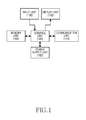
- FIG. 1 is a block diagram illustrating the configuration of a portable terminal according to the present invention.
- a portable terminal may include a control unit 100, a power supply unit 102, a memory unit 104, an input unit 106, a display unit 108, and a communication unit 110.
- the control unit 100 controls an overall operation of the portable terminal. For example, the control unit 100 processes and controls voice communication and data communication. In addition to the general functions, according to the present invention, the control unit 100 resets a charge capacity, which means the charge capacity of a charge cable supportable by the portable terminal for charging the power supply unit 102, according to the charge capacity of a charge cable, to enable the use of charge cables of various capacities.
- a charge capacity means the charge capacity of a charge cable supportable by the portable terminal for charging the power supply unit 102, according to the charge capacity of a charge cable, to enable the use of charge cables of various capacities.
- control unit 100 detects the voltage of charging power, which is provided from a charge cable connected to the portable terminal, to determine whether the charge capacity of the charge cable corresponds to the charge capacity of the portable terminal, and resets the charge capacity of the portable terminal according to the charge capacity of the charge cable.
- the power supply unit 102 includes a charge IC to control the supply of charging power provided thereto from the charge cable.
- the power supply unit 102 may detect the output voltage and current of the charge IC to control the power supplied to a battery. For example, when the output voltage of the charge IC is higher than a predetermined voltage (for example, 4.2volt), or/and when the output current of the charge IC is higher than a predetermined current(for example, 1,000mA), and therefore, charging is larger than the charge capacity of the portable terminal, the portable terminal interrupts the supply of charging power through the charge IC to the battery.
- a predetermined voltage for example, 4.2volt
- the power supply unit 102 may detect the input voltage of the charge IC to control the charge capacity of the portable terminal.
- the charge capacity of the portable terminal is the charge capacity of a charge cable supportable by the portable terminal.
- the power supply unit 102 resets the charge capacity of the portable terminal according to the charge capacity of the charge cable.
- the memory unit 104 includes at least one of a ROM, a RAM, and a flash ROM.
- the ROM stores various reference data and microcodes of a program for the processing and control of the control unit 100 and the power supply unit 102.
- the RAM is a working memory of the control unit 100, which stores temporary data that are generated during the execution of various programs.
- the flash ROM stores various updatable data such as a phone book, outgoing messages, and incoming messages of the portable terminal. According to an exemplary embodiment of the present invention, the flash ROM stores the charge capacity value of the portable terminal that is reset by the power supply unit 102.
- the method described hereunder of the present invention may be provided as one or more instructions in one or more software modules stored in the memory unit 104.
- the software modules may be executed by the control unit 100.
- the input unit 106 includes keys associated with a plurality of symbols, such as alphanumeric symbols, including numeric keys for digits 0 - 9 and a plurality of function keys, such as a Menu key, a Cancel (Delete) key, a Confirmation key, a Talk key, an End key, an Internet connection key, Navigation keys (or Direction keys), and character input keys.
- the input unit 106 provides the control unit 100 with key input data that corresponds to a key pressed by the user.
- the display unit 108 displays numerals and characters, moving pictures, still pictures, and status information generated during an operation of the portable terminal.
- the display unit 108 may include at least one of a color liquid crystal display (LCD) and an active-matrix organic light-emitting diode (AMOLED). If the display unit 108 has a touch input device and is applied to a touch input type portable terminal, the display unit 108 can be used as an input device.
- LCD color liquid crystal display
- AMOLED active-matrix organic light-emitting diode
- the input unit 106 and display unit 108 could all be served by a single touch screen. That is, a touch sensitive display, called as a touch screen, may be used as the display unit 108 as well as the input unit 106. In this situation, touch input may be performed via the touch sensitive display.
- a touch sensitive display called as a touch screen
- the communication unit 110 transmits/receives Radio Frequency (RF) signals inputted/outputted through an antenna (not illustrated). For example, in a transmitting (TX) mode, the communication unit 110 channel-encodes, spreads and RF-processes TX data prior to transmission. In a receiving (RX) mode, the communication unit 110 converts a received RF signal into a baseband signal and despreads and channel-decodes the baseband signal to restore the original data.
- TX transmitting
- RX receiving
- control unit 100 may be configured to also perform all or some of the respective functions on behalf of such separate units.
- an electronic device comprises one or more of a controller, a touch screen, a memory, and one or more software modules stored in the memory configured for execution by the controller, and the software modules comprise one or more instructions to perform the methods described hereunder.
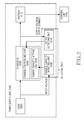
- FIG. 2 is a block diagram illustrating the configuration of the power supply unit 102 according to the exemplary embodiment of the present invention.
- the power supply unit 102 may include a port 200, a charge IC 202, a detector 207, and a battery 212.
- the charge IC 202 may include a charge controlling unit 204 and a charge capacity setting unit 206.
- the detector 207 may include a charge capacity detecting unit 208 and an output detecting unit 210.
- the port 200 may be connected to a charge cable for an external power supply.
- the port 200 may optionally be disconnected from the charge cable when charging is not desired or when charging is completed.
- the port 200 receives external power, which is supplied through the charge cable from the external power supply, and provides the external power to the charge IC 202.
- the charge IC 202 changes the external power, which is received from the external power supply through the port 200, into power suitable for charging the battery 212.
- the charge IC 202 converts 5V external power, received from the port 200, to 4V charging power, and provides the 4V charging power to the battery 212 to charge the battery 212. It is understood that other voltage values of the external power and the charging power to the battery 212 may be used, depending on the operating characteristics of the components.
- the charge controlling unit 204 of the charge IC 202 controls the supply of charging power to the battery 212 by using the output voltage and output current of the charge IC 202 detected by the output detecting unit 210 of the detector 207. For example, when the output voltage of the charge IC 202 is higher than a predetermined voltage, or when the output current of the charge IC 202 is larger than the charge capacity of the portable terminal, the charge controlling unit 204 interrupts the supply of charging power through the charge IC 202 to the battery 212 to avoid damaging the electronic components of the portable terminal.
- the charge capacity setting unit 206 of the charge IC 202 sets the charge capacity of the portable terminal according to the capacity of a connected charge cable, by using the input voltage of the charge IC 202 detected by the charge capacity detecting unit 208 of the detector 207. Accordingly, charging power can be supplied to the battery 212 even when the charge capacity of a charge cable connected to the portable terminal is different from the charge capacity of the portable terminal.
- the charge capacity setting unit 206 resets a preset or previously set charge capacity '700 mA' of the portable terminal to 500 mA.
- circuits known in the art using internal switches or other components such as capacitors and rectifiers, may be connected to the charge cable to receive and handle the higher or lower values of currents and voltages of the charging power provided by the charge cable.
- the battery 212 charges by using the charging power received from the charge IC 202, and supplies power to the control unit 100 for an operation of the portable terminal.
- the output detecting unit 210 of the detector 207 detects the voltage and current of the charging power provided through the charge IC 202 to the battery 212 (i.e., the output voltage and output current). This is to control the power supplied to the battery 212.
- the output detecting unit 210 detects the output voltage and output current of the charge IC 202, determines whether to supply power to the battery 212, and provides the power to the charge controlling unit 204.
- the output detecting unit 210 interrupts power supplied to the battery 212.
- a predetermined output voltage e.g., 4.2 V
- the output detecting unit 210 interrupts power supplied to the battery 212.
- the output current of the charge IC 202 is larger than a charge capacity (e.g., 1000 mA) set in the portable terminal
- the output detecting unit 210 interrupts power supplied to the battery 212.
- the charge capacity detecting unit 208 of the detector 207 detects the input voltage of the charge IC 202 to detect the charge capacity of a charge cable connected to the portable terminal; for example, the charge capacity is determined from voltages and currents on the charge cable in a manner known in the art.
- the charge capacity detecting unit 208 determines that a charge cable having a charge capacity lower than the charge capacity of the portable terminal is connected to the portable terminal, and controls the charge capacity of the portable terminal according to the charge capacity of the charge cable.
- the method performed using the apparatus according to FIG. 2 may be provided as one or more instructions in one or more software modules stored in a storage unit, such as the memory unit 104.
- the software modules may be executed by the control unit 100.
- FIG. 3 is a flow diagram illustrating a process for charging a battery in a portable terminal according to the exemplary embodiment of the present invention.
- the portable terminal determines whether a charge cable for an external power supply is connected to the portable terminal.
- charge cables connectable to the portable terminal may have different charge capacities.
- step 301 If the charge cable is not connected to the portable terminal in step 301, the portable terminal proceeds to step 319 to perform other functions e.g., to operate the portable terminal in an idle mode.
- step 303 the portable terminal receives external power supplied through the charge cable and provides the external power to a charge IC of a charge managing unit.
- the charge IC may be the charge IC 202
- the charge managing unit may be the power supply unit 102.
- step 305 the portable terminal operates a detector, such as the detector 207 in FIG. 2 .
- the detector 207 includes an output detecting unit 210 for detecting, in step 307, the voltage and current of charging power outputted from the charge IC 202 (i.e., the output voltage and output current), and a charge capacity detecting unit 208 for detecting the input voltage of charging power inputted to the charge IC 202 of the charge managing unit.
- the output detecting unit 210 detects the output of the charge IC 202, in step 307, to determine whether to supply charging power.
- the charge capacity detecting unit 206 detects the charge capacity of the charge cable connected to the portable terminal.
- the portable terminal measures only the output voltage and the output current through the output detecting unit 210, and controls the current of the charge IC 202 so that the output voltage does not exceed a predetermined output voltage (e.g., 4.2 V) and the output current does not exceed a current (e.g., 1000 mA) set in the portable terminal.
- a predetermined output voltage e.g., 4.2 V
- a current e.g., 1000 mA
- the present invention changes a charge capacity set in the portable terminal, by using the input voltage of the charge IC 202 detected through the charge capacity detecting unit 206. This is to enable the use of other charge cables as well as a charge cable corresponding to the charge capacity set in the portable terminal.
- the portable terminal detects the input voltage of the charge IC 202 through the charge capacity detecting unit 208.
- the portable terminal determines whether the charge capacity of the charge cable is substantially equal to the charge capacity of the portable terminal. That is, in step 309, the portable terminal determines whether the input voltage of the charge IC differs over a predetermined threshold range. For example, when a charge cable, having a capacity lower than the charge capacity set in the portable terminal, is connected to the portable terminal, the input voltage of the charge IC 202 will drop rapidly.
- step 315 the portable terminal controls the charge IC 202 through control of the output voltage and the output current. This is to control the charge IC 202 through control of the output voltage and the output current of the charge IC as in a conventional portable terminal, because the charge cable suitable for the portable terminal is connected to the portable terminal.
- step 309 if the charge capacity of the charge cable is not equal to the charge capacity of the portable terminal as detected in step 309, the portable terminal proceeds to step 311.
- the term “equal”, as used herein when comparing charge capacities may include a predetermined range of values in which compared charge capacities are considered equal within operating tolerance limits. Accordingly, the term “not equal” indicates that two compared charge capacities are not within the predetermined range of values. For example, two charge capacities which, when compared, are within 1 % in value of each other are considered equal, while, for example, two charge capacities having one value greater than the other by 1 % are not considered equal.
- step 311 the portable terminal determines that a charger, unsuitable for the charge capacity of the portable terminal, is connected to the portable terminal.
- step 313 the portable terminal changes the set or preset charge capacity of the portable terminal. The portable terminal changes the set charge capacity to be substantially equal to the charge capacity of the connected charge cable.
- step 315 the portable terminal controls the charge IC 202 through control of the output voltage and the output current.
- step 317 the portable terminal determines whether the connection of the charge cable is released or removed, for example, by disengaging the charge cable from the port 200 in FIG. 2 .
- step 317 If the connection of the charge cable is maintained in step 317, the portable terminal returns to step 303 to receive external power.
- the portable terminal ends the method of FIG. 3 , performed according to the present invention.
- the method performed according to FIG. 3 may be provided as one or more instructions in one or more software modules stored in the storage unit, such as the memory unit 104.
- the software modules may be executed by the control unit 100.
- the computer readable storage medium stores one or more programs (software modules), the one or more programs comprising instructions, which when executed by one or more processors in an electronic device, cause the electronic device to perform a method of the present invention.
- Any such software may be stored in the form of volatile or non-volatile storage such as, for example, a storage device like a ROM, whether erasable or rewritable or not, or in the form of memory such as, for example, RAM, memory chips, device or integrated circuits or on an optically or magnetically readable medium such as, for example, a CD, DVD, magnetic disk or magnetic tape or the like.
- volatile or non-volatile storage such as, for example, a storage device like a ROM, whether erasable or rewritable or not
- memory such as, for example, RAM, memory chips, device or integrated circuits or on an optically or magnetically readable medium such as, for example, a CD, DVD, magnetic disk or magnetic tape or the like.
- the storage devices and storage media are embodiments of machine-readable storage that are suitable for storing a program or programs comprising instructions that, when executed, implement embodiments of the present invention.
- embodiments provide a program comprising code for implementing the apparatus or a method as claimed in any one of the claims of this specification and a machine-readable storage storing such a program. Still further, such programs may be conveyed electronically via any medium such as a communication signal carried over a wired or wireless connection and embodiments suitably encompass the same.
- the above-described apparatus and methods according to the present invention can be implemented in hardware, firmware or as software or computer code that can be stored in a recording medium such as a CD ROM, a RAM, a ROM, a floppy disk, DVDs, a hard disk, a magnetic storage media, an optical recording media, or a magneto-optical disk or computer code downloaded over a network originally stored on a remote recording medium, a computer readable recording medium, or a non-transitory machine readable medium and to be stored on a local recording medium, so that the methods described herein can be rendered in such software that is stored on the recording medium using a general purpose computer, a digital computer, or a special processor or in programmable or dedicated hardware, such as an ASIC or FPGA.
- a recording medium such as a CD ROM, a RAM, a ROM, a floppy disk, DVDs, a hard disk, a magnetic storage media, an optical recording media, or a magneto-optical disk or computer code downloaded over
- the computer, the processor, microprocessor controller or the programmable hardware include memory components, e.g., RAM, ROM, Flash, etc. that may store or receive software or computer code that when accessed and executed by the computer, processor or hardware implement the processing methods described herein.
- memory components e.g., RAM, ROM, Flash, etc.
- the execution of the code transforms the general purpose computer into a special purpose computer for executing the processing shown herein.
- the present invention resets the charge capacity of the portable terminal according to the charging capacity of the connected charge cable in order to improve the charge performance of the portable terminal, thus making it possible to charge the battery by using charge cables of various capacities.
Landscapes
- Engineering & Computer Science (AREA)
- Power Engineering (AREA)
- Computer Networks & Wireless Communication (AREA)
- Signal Processing (AREA)
- Charge And Discharge Circuits For Batteries Or The Like (AREA)
Abstract
Description
- The present invention relates generally to a power supply apparatus of a portable terminal, and in particular, to an apparatus and method for enabling a power supply for charging a battery in a portable terminal regardless of the charge capacity of a charge cable of an external power supply.
- Recently, the use of portable terminals is rapidly increasing due to their portability. Thus, service providers (terminal manufacturers) are competitively developing portable terminals with more convenient functions in order to attract more users.
- For example, portable terminals provide various functions such as a phone book, a game, a scheduler, a Short Message Service (SMS), a Multimedia Message Service (MMS), an Internet service, an Electronic (E)-mail service, a wake-up call, a Motion Picture Expert Group (MPEG) Audio Layer-3 (MP3) player, and a digital camera.
- The portable terminal uses a rechargeable battery in order to provide the advantage of mobility. However, the rechargeable battery has a limited capacity to be charged, and the lifetime of the rechargeable battery decreases with an increase in the use time of the portable terminal. Therefore, when a user of the portable terminal is out or is in long-term travel, the user always has to check the charged state of the rechargeable battery and has to charge the rechargeable battery by an external power supply.
- In general, a separate charger, such as a travel charger (TC) or a travel adapter (TA), is used to charge the rechargeable battery by an external power supply.
- The charger converts available power, such as power from home-based electrical outlets in the range of 110 - 220 VAC, or power supplied from a computer, into DC power necessary to charge the portable terminal, and provides the DC power to the portable terminal. The portable terminal charges the battery by the DC power, and operates by the power supplied from the charged battery.
- In general, the portable terminal controls the external power supply of a charge Integrated Circuit (IC) by detecting the voltage and current of charging power provided to the battery. Herein, the voltage and current of charging power provided to the battery is the output voltage and output current of the charge IC.
- Specifically, when the output voltage of charging power provided to the battery is higher than a predetermined threshold value (for example, 4.2 volt), the portable terminal interrupts the charging power supply to the battery to avoid damaging the charging electronics or the battery.
- Also, when the output current of charging power provided to the battery is larger than a predetermined threshold value (for example, 1,000mA), the portable terminal interrupts the charging power supply to the battery to avoid damaging the charging electronics or the battery.
- Accordingly, the portable terminal controls an operation of the charge IC so that the output voltage/current value satisfies the predetermined threshold value.
- However, a charge capacity, which means the charge capacity of a charge cable supportable by the portable terminal to provide appropriate or maximum allowable values of voltage and current to charge a device, is set in the portable terminal.
- Accordingly, the portable terminal cannot charge the battery when the charge capacity of a charge cable connected to the portable terminal does not correspond to the charge capacity of the portable terminal.
- Charge cables supporting various charge capacities are popularized, and a user may have a plurality of charge cables. However, the user can use only the charge cable suitable for a charge capacity set in a portable terminal.
- What is therefore required is an apparatus and method for charging a battery in a portable terminal by using charge cables of various capacities.
- An object of the present invention is to solve the above- stated problems occurring in the prior art.
- A further object of the invention is to provide an apparatus and method for charging a battery in a portable terminal by using charge cables of various capacities.
- A further object of the invention is to provide an apparatus and method for resetting a charge capacity in a portable terminal according to the charge capacity of a connected charge cable.
- According to an aspect of the present invention, at least one of these objects is achieved by providing an apparatus for controlling a charging current in a portable terminal comprising, a detector for detecting power supplied to a battery and for detecting a charge capacity of a charge cable when the charge cable is connected to supply external power; and a charge Integrated Circuit (IC) for resetting a charge capacity of the portable terminal according to the charge capacity of the charge cable, and for controlling the power supplied to the battery according to an operation of the detector, when the charge capacity of the charge cable detected by the detector is not equal to the charge capacity of the portable terminal.
- According to another aspect of the present invention, at least one of these object is achieved by providing a method for controlling a charging current in a portable terminal comprising: operating a detector to detect power supplied to a battery and a charge capacity of a charge cable when the charge cable is connected to supply external power; resetting a charge capacity of the portable terminal according to the charge capacity of the charge cable when the charge capacity of the charge cable detected by the detector is not equal to the charge capacity of the portable terminal; and controlling the power supplied to the battery according to an operation of the detector.
- Further advantageous embodiments of the invention are defined in the dependent claims.
- The above and other objects, features and advantages of the present invention will become more apparent from the following detailed description when taken in conjunction with the accompanying drawings in which:
-
FIG. 1 is a block diagram illustrating the configuration of a portable terminal according to the present invention; -
FIG. 2 is a block diagram illustrating the configuration of a power supply unit according to an exemplary embodiment of the present invention; and -
FIG. 3 is a flow diagram illustrating a process for charging a battery in a portable terminal according to the exemplary embodiment of the present invention. - Preferred embodiments of the present invention will be described herein below with reference to the accompanying drawings. In the following description, detailed descriptions of well-known functions or configurations will be omitted since they would unnecessarily obscure the subject matters of the present invention. This invention may, however, be embodied in many different forms and should not be construed as limited to the exemplary embodiments set forth herein. The same reference numbers are used throughout the drawings to refer to the same or like parts. Also, terms described herein, which are defined considering the functions of the present invention, may be implemented differently depending on user and operator's intention and practice. Therefore, the terms should be understood on the basis of the disclosure throughout the specification. The principles and features of this invention may be employed in varied and numerous embodiments without departing from the scope of the invention.
- Furthermore, although the drawings represent exemplary embodiments of the invention, the drawings are not necessarily to scale and certain features may be exaggerated or omitted in order to more clearly illustrate and explain the present invention.
- Among the terms set forth herein, a terminal refers to any kind of device capable of processing data which is transmitted or received to or from any external entity. The terminal may display icons or menus on a screen to which stored data and various executable functions are assigned or mapped. The terminal may include a computer, a notebook, a tablet PC, a mobile device, and the like.
- Among the terms set forth herein, a screen refers to a display or other output devices which visually display information to the user, and which optionally are capable of receiving and electronically processing tactile inputs from a user using a stylo, a finger of the user, or other techniques for conveying a user selection from the user to the output devices.
-
FIG. 1 is a block diagram illustrating the configuration of a portable terminal according to the present invention. - Referring to
FIG. 1 , a portable terminal according to the present invention may include acontrol unit 100, apower supply unit 102, amemory unit 104, aninput unit 106, adisplay unit 108, and acommunication unit 110. - The
control unit 100 controls an overall operation of the portable terminal. For example, thecontrol unit 100 processes and controls voice communication and data communication. In addition to the general functions, according to the present invention, thecontrol unit 100 resets a charge capacity, which means the charge capacity of a charge cable supportable by the portable terminal for charging thepower supply unit 102, according to the charge capacity of a charge cable, to enable the use of charge cables of various capacities. - That is, the
control unit 100 detects the voltage of charging power, which is provided from a charge cable connected to the portable terminal, to determine whether the charge capacity of the charge cable corresponds to the charge capacity of the portable terminal, and resets the charge capacity of the portable terminal according to the charge capacity of the charge cable. - The
power supply unit 102 includes a charge IC to control the supply of charging power provided thereto from the charge cable. Thepower supply unit 102 may detect the output voltage and current of the charge IC to control the power supplied to a battery. For example, when the output voltage of the charge IC is higher than a predetermined voltage (for example, 4.2volt), or/and when the output current of the charge IC is higher than a predetermined current(for example, 1,000mA), and therefore, charging is larger than the charge capacity of the portable terminal, the portable terminal interrupts the supply of charging power through the charge IC to the battery. - In addition, the
power supply unit 102 may detect the input voltage of the charge IC to control the charge capacity of the portable terminal. Herein, the charge capacity of the portable terminal is the charge capacity of a charge cable supportable by the portable terminal. - That is, when external power is not able to be supplied because the charge capacity of a charge cable connected to the portable terminal is different from the charge capacity of the portable terminal, the
power supply unit 102 resets the charge capacity of the portable terminal according to the charge capacity of the charge cable. - The
memory unit 104 includes at least one of a ROM, a RAM, and a flash ROM. The ROM stores various reference data and microcodes of a program for the processing and control of thecontrol unit 100 and thepower supply unit 102. - The RAM is a working memory of the
control unit 100, which stores temporary data that are generated during the execution of various programs. The flash ROM stores various updatable data such as a phone book, outgoing messages, and incoming messages of the portable terminal. According to an exemplary embodiment of the present invention, the flash ROM stores the charge capacity value of the portable terminal that is reset by thepower supply unit 102. - The method described hereunder of the present invention may be provided as one or more instructions in one or more software modules stored in the
memory unit 104. The software modules may be executed by thecontrol unit 100. - The
input unit 106 includes keys associated with a plurality of symbols, such as alphanumeric symbols, including numeric keys for digits 0 - 9 and a plurality of function keys, such as a Menu key, a Cancel (Delete) key, a Confirmation key, a Talk key, an End key, an Internet connection key, Navigation keys (or Direction keys), and character input keys. Theinput unit 106 provides thecontrol unit 100 with key input data that corresponds to a key pressed by the user. - The
display unit 108 displays numerals and characters, moving pictures, still pictures, and status information generated during an operation of the portable terminal. Thedisplay unit 108 may include at least one of a color liquid crystal display (LCD) and an active-matrix organic light-emitting diode (AMOLED). If thedisplay unit 108 has a touch input device and is applied to a touch input type portable terminal, thedisplay unit 108 can be used as an input device. - In fact, it is within the scope of the presently claimed invention that the
input unit 106 anddisplay unit 108 could all be served by a single touch screen. That is, a touch sensitive display, called as a touch screen, may be used as thedisplay unit 108 as well as theinput unit 106. In this situation, touch input may be performed via the touch sensitive display. - The
communication unit 110 transmits/receives Radio Frequency (RF) signals inputted/outputted through an antenna (not illustrated). For example, in a transmitting (TX) mode, thecommunication unit 110 channel-encodes, spreads and RF-processes TX data prior to transmission. In a receiving (RX) mode, thecommunication unit 110 converts a received RF signal into a baseband signal and despreads and channel-decodes the baseband signal to restore the original data. - The above configuration should be considered in descriptive sense only and not for the purpose of limitation, and those skilled in the art will understand that various changes may be made therein without departing from the scope of the present invention. For example, although separate units, such as the
power supply unit 102, are provided for respective functions of thecontrol unit 100, thecontrol unit 100 may be configured to also perform all or some of the respective functions on behalf of such separate units. - According to the present invention, for example, an electronic device comprises one or more of a controller, a touch screen, a memory, and one or more software modules stored in the memory configured for execution by the controller, and the software modules comprise one or more instructions to perform the methods described hereunder.
-
FIG. 2 is a block diagram illustrating the configuration of thepower supply unit 102 according to the exemplary embodiment of the present invention. - Referring to
FIG. 2 , thepower supply unit 102 according to the exemplary embodiment of the present invention may include aport 200, acharge IC 202, adetector 207, and abattery 212. Thecharge IC 202 may include acharge controlling unit 204 and a chargecapacity setting unit 206. Thedetector 207 may include a chargecapacity detecting unit 208 and anoutput detecting unit 210. - The
port 200 may be connected to a charge cable for an external power supply. Theport 200 may optionally be disconnected from the charge cable when charging is not desired or when charging is completed. Theport 200 receives external power, which is supplied through the charge cable from the external power supply, and provides the external power to thecharge IC 202. - The
charge IC 202 changes the external power, which is received from the external power supply through theport 200, into power suitable for charging thebattery 212. For example, thecharge IC 202 converts 5V external power, received from theport 200, to 4V charging power, and provides the 4V charging power to thebattery 212 to charge thebattery 212. It is understood that other voltage values of the external power and the charging power to thebattery 212 may be used, depending on the operating characteristics of the components. - The
charge controlling unit 204 of thecharge IC 202 controls the supply of charging power to thebattery 212 by using the output voltage and output current of thecharge IC 202 detected by theoutput detecting unit 210 of thedetector 207. For example, when the output voltage of thecharge IC 202 is higher than a predetermined voltage, or when the output current of thecharge IC 202 is larger than the charge capacity of the portable terminal, thecharge controlling unit 204 interrupts the supply of charging power through thecharge IC 202 to thebattery 212 to avoid damaging the electronic components of the portable terminal. - The charge
capacity setting unit 206 of thecharge IC 202 sets the charge capacity of the portable terminal according to the capacity of a connected charge cable, by using the input voltage of thecharge IC 202 detected by the chargecapacity detecting unit 208 of thedetector 207. Accordingly, charging power can be supplied to thebattery 212 even when the charge capacity of a charge cable connected to the portable terminal is different from the charge capacity of the portable terminal. - For example, when the charge
capacity detecting unit 208 detects that a 500 mA charge cable is connected to the portable terminal, the chargecapacity setting unit 206 resets a preset or previously set charge capacity '700 mA' of the portable terminal to 500 mA. For example, circuits known in the art, using internal switches or other components such as capacitors and rectifiers, may be connected to the charge cable to receive and handle the higher or lower values of currents and voltages of the charging power provided by the charge cable. - The
battery 212 charges by using the charging power received from thecharge IC 202, and supplies power to thecontrol unit 100 for an operation of the portable terminal. - The
output detecting unit 210 of thedetector 207 detects the voltage and current of the charging power provided through thecharge IC 202 to the battery 212 (i.e., the output voltage and output current). This is to control the power supplied to thebattery 212. - That is, the
output detecting unit 210 detects the output voltage and output current of thecharge IC 202, determines whether to supply power to thebattery 212, and provides the power to thecharge controlling unit 204. - For example, when the output voltage of the
charge IC 202 is higher than a predetermined output voltage (e.g., 4.2 V), theoutput detecting unit 210 interrupts power supplied to thebattery 212. Also, when the output current of thecharge IC 202 is larger than a charge capacity (e.g., 1000 mA) set in the portable terminal, theoutput detecting unit 210 interrupts power supplied to thebattery 212. - The charge
capacity detecting unit 208 of thedetector 207 detects the input voltage of thecharge IC 202 to detect the charge capacity of a charge cable connected to the portable terminal; for example, the charge capacity is determined from voltages and currents on the charge cable in a manner known in the art. - For example, when detecting that the input voltage of the
charge IC 202 is lower than a predetermined value, the chargecapacity detecting unit 208 determines that a charge cable having a charge capacity lower than the charge capacity of the portable terminal is connected to the portable terminal, and controls the charge capacity of the portable terminal according to the charge capacity of the charge cable. - The method performed using the apparatus according to
FIG. 2 may be provided as one or more instructions in one or more software modules stored in a storage unit, such as thememory unit 104. In that case, the software modules may be executed by thecontrol unit 100. -
FIG. 3 is a flow diagram illustrating a process for charging a battery in a portable terminal according to the exemplary embodiment of the present invention. - Referring to
FIG. 3 , instep 301, the portable terminal determines whether a charge cable for an external power supply is connected to the portable terminal. Herein, charge cables connectable to the portable terminal may have different charge capacities. - If the charge cable is not connected to the portable terminal in
step 301, the portable terminal proceeds to step 319 to perform other functions e.g., to operate the portable terminal in an idle mode. - On the other hand, if the charge cable is connected to the portable terminal in
step 301, the portable terminal proceeds to step 303. Instep 303, the portable terminal receives external power supplied through the charge cable and provides the external power to a charge IC of a charge managing unit. For example, as shown inFIG. 2 , the charge IC may be thecharge IC 202, and the charge managing unit may be thepower supply unit 102. Instep 305, the portable terminal operates a detector, such as thedetector 207 inFIG. 2 . Herein, thedetector 207 includes anoutput detecting unit 210 for detecting, instep 307, the voltage and current of charging power outputted from the charge IC 202 (i.e., the output voltage and output current), and a chargecapacity detecting unit 208 for detecting the input voltage of charging power inputted to thecharge IC 202 of the charge managing unit. Theoutput detecting unit 210 detects the output of thecharge IC 202, instep 307, to determine whether to supply charging power. The chargecapacity detecting unit 206 detects the charge capacity of the charge cable connected to the portable terminal. - In general, the portable terminal measures only the output voltage and the output current through the
output detecting unit 210, and controls the current of thecharge IC 202 so that the output voltage does not exceed a predetermined output voltage (e.g., 4.2 V) and the output current does not exceed a current (e.g., 1000 mA) set in the portable terminal. - However, in addition to the above operation, the present invention changes a charge capacity set in the portable terminal, by using the input voltage of the
charge IC 202 detected through the chargecapacity detecting unit 206. This is to enable the use of other charge cables as well as a charge cable corresponding to the charge capacity set in the portable terminal. - Accordingly, in
step 307 inFIG. 3 , the portable terminal detects the input voltage of thecharge IC 202 through the chargecapacity detecting unit 208. Instep 309, the portable terminal determines whether the charge capacity of the charge cable is substantially equal to the charge capacity of the portable terminal. That is, instep 309, the portable terminal determines whether the input voltage of the charge IC differs over a predetermined threshold range. For example, when a charge cable, having a capacity lower than the charge capacity set in the portable terminal, is connected to the portable terminal, the input voltage of thecharge IC 202 will drop rapidly. - If the charge capacity of the charge cable is substantially equal to the charge capacity of the portable terminal in
step 309, the portable terminal proceeds to step 315. Instep 315, the portable terminal controls thecharge IC 202 through control of the output voltage and the output current. This is to control thecharge IC 202 through control of the output voltage and the output current of the charge IC as in a conventional portable terminal, because the charge cable suitable for the portable terminal is connected to the portable terminal. - On the other hand, referring back to step 309, if the charge capacity of the charge cable is not equal to the charge capacity of the portable terminal as detected in
step 309, the portable terminal proceeds to step 311. It is to be understood that the term "equal", as used herein when comparing charge capacities, may include a predetermined range of values in which compared charge capacities are considered equal within operating tolerance limits. Accordingly, the term "not equal" indicates that two compared charge capacities are not within the predetermined range of values. For example, two charge capacities which, when compared, are within 1 % in value of each other are considered equal, while, for example, two charge capacities having one value greater than the other by 1 % are not considered equal. Instep 311, the portable terminal determines that a charger, unsuitable for the charge capacity of the portable terminal, is connected to the portable terminal. Instep 313, the portable terminal changes the set or preset charge capacity of the portable terminal. The portable terminal changes the set charge capacity to be substantially equal to the charge capacity of the connected charge cable. - In
step 315, the portable terminal controls thecharge IC 202 through control of the output voltage and the output current. Instep 317, the portable terminal determines whether the connection of the charge cable is released or removed, for example, by disengaging the charge cable from theport 200 inFIG. 2 . - If the connection of the charge cable is maintained in
step 317, the portable terminal returns to step 303 to receive external power. - On the other hand, if the connection of the charge cable is released in
step 317, the portable terminal ends the method ofFIG. 3 , performed according to the present invention. - The method performed according to
FIG. 3 may be provided as one or more instructions in one or more software modules stored in the storage unit, such as thememory unit 104. In that case, the software modules may be executed by thecontrol unit 100. - It will be appreciated that embodiments of the present invention according to the claims and description in the specification can be realized in the form of hardware, software or a combination of hardware and software.
- Any such software may be stored in a computer readable storage medium. The computer readable storage medium stores one or more programs (software modules), the one or more programs comprising instructions, which when executed by one or more processors in an electronic device, cause the electronic device to perform a method of the present invention.
- Any such software may be stored in the form of volatile or non-volatile storage such as, for example, a storage device like a ROM, whether erasable or rewritable or not, or in the form of memory such as, for example, RAM, memory chips, device or integrated circuits or on an optically or magnetically readable medium such as, for example, a CD, DVD, magnetic disk or magnetic tape or the like. It will be appreciated that the storage devices and storage media are embodiments of machine-readable storage that are suitable for storing a program or programs comprising instructions that, when executed, implement embodiments of the present invention.
- Accordingly, embodiments provide a program comprising code for implementing the apparatus or a method as claimed in any one of the claims of this specification and a machine-readable storage storing such a program. Still further, such programs may be conveyed electronically via any medium such as a communication signal carried over a wired or wireless connection and embodiments suitably encompass the same.
- Therefore, the above-described apparatus and methods according to the present invention can be implemented in hardware, firmware or as software or computer code that can be stored in a recording medium such as a CD ROM, a RAM, a ROM, a floppy disk, DVDs, a hard disk, a magnetic storage media, an optical recording media, or a magneto-optical disk or computer code downloaded over a network originally stored on a remote recording medium, a computer readable recording medium, or a non-transitory machine readable medium and to be stored on a local recording medium, so that the methods described herein can be rendered in such software that is stored on the recording medium using a general purpose computer, a digital computer, or a special processor or in programmable or dedicated hardware, such as an ASIC or FPGA. As would be understood in the art, the computer, the processor, microprocessor controller or the programmable hardware include memory components, e.g., RAM, ROM, Flash, etc. that may store or receive software or computer code that when accessed and executed by the computer, processor or hardware implement the processing methods described herein. In addition, it would be recognized that when a general purpose computer accesses code for implementing the processing shown herein, the execution of the code transforms the general purpose computer into a special purpose computer for executing the processing shown herein.
- As described above, the present invention resets the charge capacity of the portable terminal according to the charging capacity of the connected charge cable in order to improve the charge performance of the portable terminal, thus making it possible to charge the battery by using charge cables of various capacities.
- While the invention has been shown and described with reference to certain exemplary embodiments thereof, it will be understood by those skilled in the art that various changes in form and details may be made therein without departing from the scope of the invention as defined by the appended claims. Therefore, the scope of the invention is defined not by the detailed description of the invention but by the appended claims, and all differences within the scope will be construed as being included in the present invention.
Claims (15)
- An apparatus for controlling a charge current in a portable terminal, comprising:a detector for detecting power supplied to a battery and for detecting a charge capacity of a charge cable when the charge cable is connected to supply external power; anda charge Integrated Circuit (IC) for resetting a charge capacity of the portable terminal according to the charge capacity of the charge cable, and for controlling the power supplied to the battery according to an operation of the detector, when the charge capacity of the charge cable detected by the detector is not equal to the charge capacity of the portable terminal.
- The apparatus of claim 1, wherein the detector comprises:a charge capacity detecting unit for detecting a voltage of charging power inputted to the charge IC; andan output detecting unit for detecting a voltage and a current of charging power outputted from the charge IC.
- The apparatus of claim 1, wherein the detector detects a voltage of charging power inputted to the charge IC, determines whether the detected voltage differs over a predetermined threshold range, and determines that the charge capacity of the connected charge cable is not equal to the charge capacity of the portable terminal, if the detected voltage differs over the predetermined threshold range.
- The apparatus of claim 1, wherein the detector compares an output voltage and current of the charge IC with a predetermined threshold value and controls the output voltage and current to correspond to the predetermined threshold value.
- A method for controlling a charge current in a portable terminal, comprising:operating a detector to detect power supplied to a battery and a charge capacity of a charge cable when the charge cable is connected to supply external power;resetting a charge capacity of the portable terminal according to the charge capacity of the charge cable when the charge capacity of the charge cable detected by the detector is not equal to the charge capacity of the portable terminal; andcontrolling the power supplied to the battery according to an operation of the detector.
- The method of claim 5, wherein operating the detector comprises:detecting a voltage of charging power inputted to a charge Integrated Circuit (IC); anddetecting a voltage and a current of charging power outputted from the charge IC.
- The method of claim 5, wherein detecting the charge capacity of the charge cable comprises:detecting a voltage of charging power inputted to a charge IC;determining whether the detected voltage differs over a predetermined threshold range; anddetermining that the charge capacity of the connected charge cable is not equal to the charge capacity of the portable terminal, if the detected voltage differs over the predetermined threshold range.
- The method of claim 5, wherein controlling the power supplied to the battery according to the operation of the detector comprises:compares an output voltage and current of a charge IC with a predetermined threshold value; andcontrolling the output voltage and current to correspond to the predetermined threshold value.
- The apparatus of claim 1, wherein the charge IC further comprises:a charge capacity setting unit for resetting the charge capacity.
- The method of claim 5, further comprising:determining, using a control unit, that a charge cable having a charge capacity lower than the charge capacity of the portable terminal is connected to the portable terminal, when detecting that an input voltage drops below a predetermined value.
- The method of claim 5, further comprising:controlling the power supplied to the battery using a charge controlling unit.
- The method of claim 5, wherein the resetting of the charge capacity includes:resetting the charge capacity using a charge capacity setting unit.
- The apparatus of claim 9, wherein the control unit includes:a charge capacity detecting unit for detecting an input voltage of charging power; andan output detecting unit for detecting an output voltage and an output current of charging power.
- The apparatus of claim 9, wherein the control unit includes:a detector for detecting an input voltage of charging power, for determining whether the detected voltage differs over a predetermined threshold range, and for determining that the charge capacity of the connected charge cable is not equal to the charge capacity of the portable terminal, if the detected voltage differs over the predetermined threshold range.
- The apparatus of claim 9, wherein the control unit includes:a detector for comparing an output voltage and an output current with a predetermined threshold value, and for controlling the output voltage and current to correspond to the predetermined threshold value.
Applications Claiming Priority (1)
| Application Number | Priority Date | Filing Date | Title |
|---|---|---|---|
| KR1020110109282A KR101835007B1 (en) | 2011-10-25 | 2011-10-25 | Apparatus and mathod for controlling charge current in portable terminal |
Publications (3)
| Publication Number | Publication Date |
|---|---|
| EP2587617A2 true EP2587617A2 (en) | 2013-05-01 |
| EP2587617A3 EP2587617A3 (en) | 2017-04-26 |
| EP2587617B1 EP2587617B1 (en) | 2019-10-02 |
Family
ID=47623775
Family Applications (1)
| Application Number | Title | Priority Date | Filing Date |
|---|---|---|---|
| EP12190004.7A Not-in-force EP2587617B1 (en) | 2011-10-25 | 2012-10-25 | Apparatus and method for controlling charge current in portable terminal |
Country Status (4)
| Country | Link |
|---|---|
| US (1) | US9509165B2 (en) |
| EP (1) | EP2587617B1 (en) |
| KR (1) | KR101835007B1 (en) |
| CN (1) | CN103078359B (en) |
Families Citing this family (6)
| Publication number | Priority date | Publication date | Assignee | Title |
|---|---|---|---|---|
| CN105980956B (en) * | 2014-02-18 | 2020-05-12 | 惠普发展公司,有限责任合伙企业 | Cable error signal |
| US12314872B2 (en) | 2015-04-22 | 2025-05-27 | Aeris Communications, Inc. | Method and system for optimizing execution of user commands in relation to power management |
| US9978018B2 (en) | 2015-04-22 | 2018-05-22 | Aeris Communications, Inc. | Method and system for optimizing execution of user commands in relation to power management |
| CN104967181B (en) * | 2015-07-15 | 2017-03-29 | 杰华特微电子(张家港)有限公司 | A kind of charge control method and battery charge controller of charger |
| CN107994622A (en) * | 2016-10-26 | 2018-05-04 | 宁德时代新能源科技股份有限公司 | Battery power supply circuit |
| US11491884B2 (en) * | 2017-01-19 | 2022-11-08 | Curtis Instruments Inc. | Magnetic charger connector for wheelchair |
Family Cites Families (30)
| Publication number | Priority date | Publication date | Assignee | Title |
|---|---|---|---|---|
| JPH10327536A (en) | 1997-05-23 | 1998-12-08 | Pacific Ind Co Ltd | Charging circuit |
| JP4186092B2 (en) * | 1999-08-18 | 2008-11-26 | ソニー株式会社 | Battery device and battery management method |
| CN1249877C (en) * | 2001-12-13 | 2006-04-05 | 广达电脑股份有限公司 | Charging device that can dynamically adjust charging power |
| KR200330467Y1 (en) * | 2003-08-01 | 2003-10-17 | (주) 피엔텔레컴 | Data cable for detecting power source automatically |
| SG124315A1 (en) * | 2005-01-31 | 2006-08-30 | Stl Corp | Battery pack |
| CN1881738B (en) | 2005-06-17 | 2011-06-22 | 鸿富锦精密工业(深圳)有限公司 | Charge mode control circuit and method |
| US8242742B2 (en) | 2007-06-06 | 2012-08-14 | O2Micro, Inc | Chargers, systems and methods for detecting a power source |
| JP4640391B2 (en) * | 2007-08-10 | 2011-03-02 | トヨタ自動車株式会社 | Power supply system and vehicle equipped with the same |
| US7782022B2 (en) | 2007-10-19 | 2010-08-24 | Texas Instruments Incorporated | Input source detection for a battery charger |
| KR101024676B1 (en) * | 2008-04-10 | 2011-03-25 | 광주과학기술원 | Power-on reset circuit |
| US9166429B2 (en) * | 2008-06-03 | 2015-10-20 | Intersil Americas LLC | USB charger using current limit |
| CN201290022Y (en) * | 2008-08-29 | 2009-08-12 | 宇龙计算机通信科技(深圳)有限公司 | Charging hubs for mobile terminal |
| JPWO2010055576A1 (en) * | 2008-11-14 | 2012-04-05 | 富士通株式会社 | Charging circuit, electronic device, program, charging method, and power supply device |
| JP2010154692A (en) | 2008-12-25 | 2010-07-08 | Nikon Corp | Charger for electronic device, electronic device, and charging method |
| JP5343981B2 (en) * | 2009-02-03 | 2013-11-13 | トヨタ自動車株式会社 | Vehicle charging system |
| CN101483351B (en) * | 2009-02-13 | 2012-11-28 | 陈宗映 | Universal charger |
| US8098506B2 (en) | 2009-06-02 | 2012-01-17 | Power Integrations, Inc. | Single-stage power supply with power factor correction and constant current output |
| KR101084828B1 (en) * | 2009-10-12 | 2011-11-21 | 삼성에스디아이 주식회사 | How to control the charge of the battery pack |
| KR101667707B1 (en) * | 2009-10-22 | 2016-10-19 | 엘지전자 주식회사 | Mobile terminal and usb dedicated charger determinating method thereof |
| CN201656537U (en) | 2010-02-10 | 2010-11-24 | 王业欣 | Accumulator charger |
| EP2555008A4 (en) * | 2010-03-30 | 2013-08-28 | Honda Motor Co Ltd | METHOD FOR DETECTING BATTERY CAPACITY OF SECONDARY BATTERY |
| KR101672736B1 (en) * | 2010-05-14 | 2016-11-04 | 삼성전자주식회사 | Apparatus and method for power and data transmission using mobile device |
| JP5170165B2 (en) * | 2010-06-11 | 2013-03-27 | 株式会社村田製作所 | Isolated switching power supply |
| KR101161966B1 (en) * | 2010-07-09 | 2012-07-04 | 에스케이하이닉스 주식회사 | Multi chip package having a chip address circuit |
| KR101771452B1 (en) * | 2010-08-23 | 2017-08-25 | 엘지전자 주식회사 | Mobile terminal and usb dedicated charger determinating method thereof |
| KR20120028472A (en) * | 2010-09-15 | 2012-03-23 | 삼성전자주식회사 | Apparatus and method for charging of battery in portable terminal |
| TW201217961A (en) * | 2010-10-20 | 2012-05-01 | Hon Hai Prec Ind Co Ltd | Conversion efficiency testing device and using the same |
| US20120139345A1 (en) * | 2010-12-01 | 2012-06-07 | Texas Instruments Incorporated | Control method of hybrid power battery charger |
| US8793086B2 (en) * | 2011-02-23 | 2014-07-29 | Blackberry Limited | Method and system for detecting power supply source electrical current capacity |
| US9197086B2 (en) * | 2012-04-30 | 2015-11-24 | Hewlett-Packard Development Company, L.P. | Boosting input power |
-
2011
- 2011-10-25 KR KR1020110109282A patent/KR101835007B1/en active Active
-
2012
- 2012-10-25 EP EP12190004.7A patent/EP2587617B1/en not_active Not-in-force
- 2012-10-25 CN CN201210411813.0A patent/CN103078359B/en not_active Expired - Fee Related
- 2012-10-25 US US13/660,231 patent/US9509165B2/en active Active
Non-Patent Citations (1)
| Title |
|---|
| None |
Also Published As
| Publication number | Publication date |
|---|---|
| CN103078359A (en) | 2013-05-01 |
| CN103078359B (en) | 2018-04-06 |
| KR101835007B1 (en) | 2018-03-07 |
| EP2587617B1 (en) | 2019-10-02 |
| US9509165B2 (en) | 2016-11-29 |
| KR20130044924A (en) | 2013-05-03 |
| EP2587617A3 (en) | 2017-04-26 |
| US20130099758A1 (en) | 2013-04-25 |
Similar Documents
| Publication | Publication Date | Title |
|---|---|---|
| EP2587617B1 (en) | Apparatus and method for controlling charge current in portable terminal | |
| EP3121926B1 (en) | Charging method and apparatus | |
| CN110225167B (en) | Terminal and processing method | |
| US9160180B2 (en) | Charging apparatus for charging a secondary battery with a wireless feeding method | |
| WO2018129992A1 (en) | Terminal and method for charging the same | |
| EP4513712A2 (en) | Electronic device and battery charge/discharge control method thereof | |
| US9692253B2 (en) | Mobile terminal and method for controlling charging and charger therefor | |
| KR102648609B1 (en) | Electronic device for controlling wireless charging and method for controlling thereof | |
| CN106797127B (en) | Electronic device, method for controlling charging through electronic device and method for supplying power through power supply device | |
| KR20100072857A (en) | Controlling method of interrupt and potable device using the same | |
| KR102052443B1 (en) | System for performing charging and data communication | |
| CN106356925A (en) | Mobile terminal, and charge control device and method thereof | |
| EP3570404B1 (en) | Power supply control method and apparatus, storage medium, and electronic device | |
| CN112311029B (en) | A charging method, electronic device and storage medium | |
| CN106786961A (en) | Charging process method, device and terminal | |
| CN105162193A (en) | Charging method and charging apparatus for terminal, and terminal | |
| US8909955B2 (en) | Method and apparatus for providing characteristics information of a peripheral device to an electronic device by encoding the characteristic information into a power signal | |
| CN103605077A (en) | Predetermined battery identification method, predetermined battery identification device and electronic equipment | |
| US9448199B2 (en) | Apparatus and method for determining battery current consumption in a portable terminal | |
| EP3614523B1 (en) | Charging processing method and terminal device | |
| EP4037127B1 (en) | Charging method and device, terminal, and storage medium | |
| US20150102670A1 (en) | Method for operating booting and electronic device thereof | |
| US10248841B2 (en) | Method of protecting an image based on face recognition, and smart terminal | |
| EP2544330A1 (en) | Accessory ID recognition by power cycling | |
| CN111984107B (en) | Method and device for handling abnormal power supply of terminal equipment |
Legal Events
| Date | Code | Title | Description |
|---|---|---|---|
| PUAI | Public reference made under article 153(3) epc to a published international application that has entered the european phase |
Free format text: ORIGINAL CODE: 0009012 |
|
| AK | Designated contracting states |
Kind code of ref document: A2 Designated state(s): AL AT BE BG CH CY CZ DE DK EE ES FI FR GB GR HR HU IE IS IT LI LT LU LV MC MK MT NL NO PL PT RO RS SE SI SK SM TR |
|
| AX | Request for extension of the european patent |
Extension state: BA ME |
|
| PUAL | Search report despatched |
Free format text: ORIGINAL CODE: 0009013 |
|
| AK | Designated contracting states |
Kind code of ref document: A3 Designated state(s): AL AT BE BG CH CY CZ DE DK EE ES FI FR GB GR HR HU IE IS IT LI LT LU LV MC MK MT NL NO PL PT RO RS SE SI SK SM TR |
|
| AX | Request for extension of the european patent |
Extension state: BA ME |
|
| RIC1 | Information provided on ipc code assigned before grant |
Ipc: H02J 7/00 20060101AFI20170323BHEP |
|
| STAA | Information on the status of an ep patent application or granted ep patent |
Free format text: STATUS: REQUEST FOR EXAMINATION WAS MADE |
|
| 17P | Request for examination filed |
Effective date: 20170802 |
|
| RBV | Designated contracting states (corrected) |
Designated state(s): AL AT BE BG CH CY CZ DE DK EE ES FI FR GB GR HR HU IE IS IT LI LT LU LV MC MK MT NL NO PL PT RO RS SE SI SK SM TR |
|
| STAA | Information on the status of an ep patent application or granted ep patent |
Free format text: STATUS: EXAMINATION IS IN PROGRESS |
|
| 17Q | First examination report despatched |
Effective date: 20180515 |
|
| GRAP | Despatch of communication of intention to grant a patent |
Free format text: ORIGINAL CODE: EPIDOSNIGR1 |
|
| STAA | Information on the status of an ep patent application or granted ep patent |
Free format text: STATUS: GRANT OF PATENT IS INTENDED |
|
| INTG | Intention to grant announced |
Effective date: 20190621 |
|
| GRAS | Grant fee paid |
Free format text: ORIGINAL CODE: EPIDOSNIGR3 |
|
| GRAA | (expected) grant |
Free format text: ORIGINAL CODE: 0009210 |
|
| STAA | Information on the status of an ep patent application or granted ep patent |
Free format text: STATUS: THE PATENT HAS BEEN GRANTED |
|
| AK | Designated contracting states |
Kind code of ref document: B1 Designated state(s): AL AT BE BG CH CY CZ DE DK EE ES FI FR GB GR HR HU IE IS IT LI LT LU LV MC MK MT NL NO PL PT RO RS SE SI SK SM TR |
|
| REG | Reference to a national code |
Ref country code: GB Ref legal event code: FG4D |
|
| REG | Reference to a national code |
Ref country code: CH Ref legal event code: EP Ref country code: AT Ref legal event code: REF Ref document number: 1187278 Country of ref document: AT Kind code of ref document: T Effective date: 20191015 |
|
| REG | Reference to a national code |
Ref country code: DE Ref legal event code: R096 Ref document number: 602012064475 Country of ref document: DE |
|
| REG | Reference to a national code |
Ref country code: IE Ref legal event code: FG4D |
|
| REG | Reference to a national code |
Ref country code: NL Ref legal event code: FP |
|
| REG | Reference to a national code |
Ref country code: LT Ref legal event code: MG4D |
|
| REG | Reference to a national code |
Ref country code: AT Ref legal event code: MK05 Ref document number: 1187278 Country of ref document: AT Kind code of ref document: T Effective date: 20191002 |
|
| PG25 | Lapsed in a contracting state [announced via postgrant information from national office to epo] |
Ref country code: ES Free format text: LAPSE BECAUSE OF FAILURE TO SUBMIT A TRANSLATION OF THE DESCRIPTION OR TO PAY THE FEE WITHIN THE PRESCRIBED TIME-LIMIT Effective date: 20191002 Ref country code: SE Free format text: LAPSE BECAUSE OF FAILURE TO SUBMIT A TRANSLATION OF THE DESCRIPTION OR TO PAY THE FEE WITHIN THE PRESCRIBED TIME-LIMIT Effective date: 20191002 Ref country code: LV Free format text: LAPSE BECAUSE OF FAILURE TO SUBMIT A TRANSLATION OF THE DESCRIPTION OR TO PAY THE FEE WITHIN THE PRESCRIBED TIME-LIMIT Effective date: 20191002 Ref country code: AT Free format text: LAPSE BECAUSE OF FAILURE TO SUBMIT A TRANSLATION OF THE DESCRIPTION OR TO PAY THE FEE WITHIN THE PRESCRIBED TIME-LIMIT Effective date: 20191002 Ref country code: FI Free format text: LAPSE BECAUSE OF FAILURE TO SUBMIT A TRANSLATION OF THE DESCRIPTION OR TO PAY THE FEE WITHIN THE PRESCRIBED TIME-LIMIT Effective date: 20191002 Ref country code: BG Free format text: LAPSE BECAUSE OF FAILURE TO SUBMIT A TRANSLATION OF THE DESCRIPTION OR TO PAY THE FEE WITHIN THE PRESCRIBED TIME-LIMIT Effective date: 20200102 Ref country code: PT Free format text: LAPSE BECAUSE OF FAILURE TO SUBMIT A TRANSLATION OF THE DESCRIPTION OR TO PAY THE FEE WITHIN THE PRESCRIBED TIME-LIMIT Effective date: 20200203 Ref country code: LT Free format text: LAPSE BECAUSE OF FAILURE TO SUBMIT A TRANSLATION OF THE DESCRIPTION OR TO PAY THE FEE WITHIN THE PRESCRIBED TIME-LIMIT Effective date: 20191002 Ref country code: NO Free format text: LAPSE BECAUSE OF FAILURE TO SUBMIT A TRANSLATION OF THE DESCRIPTION OR TO PAY THE FEE WITHIN THE PRESCRIBED TIME-LIMIT Effective date: 20200102 Ref country code: GR Free format text: LAPSE BECAUSE OF FAILURE TO SUBMIT A TRANSLATION OF THE DESCRIPTION OR TO PAY THE FEE WITHIN THE PRESCRIBED TIME-LIMIT Effective date: 20200103 Ref country code: PL Free format text: LAPSE BECAUSE OF FAILURE TO SUBMIT A TRANSLATION OF THE DESCRIPTION OR TO PAY THE FEE WITHIN THE PRESCRIBED TIME-LIMIT Effective date: 20191002 |
|
| PG25 | Lapsed in a contracting state [announced via postgrant information from national office to epo] |
Ref country code: RS Free format text: LAPSE BECAUSE OF FAILURE TO SUBMIT A TRANSLATION OF THE DESCRIPTION OR TO PAY THE FEE WITHIN THE PRESCRIBED TIME-LIMIT Effective date: 20191002 Ref country code: HR Free format text: LAPSE BECAUSE OF FAILURE TO SUBMIT A TRANSLATION OF THE DESCRIPTION OR TO PAY THE FEE WITHIN THE PRESCRIBED TIME-LIMIT Effective date: 20191002 Ref country code: CZ Free format text: LAPSE BECAUSE OF FAILURE TO SUBMIT A TRANSLATION OF THE DESCRIPTION OR TO PAY THE FEE WITHIN THE PRESCRIBED TIME-LIMIT Effective date: 20191002 Ref country code: IS Free format text: LAPSE BECAUSE OF FAILURE TO SUBMIT A TRANSLATION OF THE DESCRIPTION OR TO PAY THE FEE WITHIN THE PRESCRIBED TIME-LIMIT Effective date: 20200224 |
|
| REG | Reference to a national code |
Ref country code: CH Ref legal event code: PL |
|
| PG25 | Lapsed in a contracting state [announced via postgrant information from national office to epo] |
Ref country code: AL Free format text: LAPSE BECAUSE OF FAILURE TO SUBMIT A TRANSLATION OF THE DESCRIPTION OR TO PAY THE FEE WITHIN THE PRESCRIBED TIME-LIMIT Effective date: 20191002 |
|
| REG | Reference to a national code |
Ref country code: DE Ref legal event code: R097 Ref document number: 602012064475 Country of ref document: DE |
|
| PG2D | Information on lapse in contracting state deleted |
Ref country code: IS |
|
| PG25 | Lapsed in a contracting state [announced via postgrant information from national office to epo] |
Ref country code: RO Free format text: LAPSE BECAUSE OF FAILURE TO SUBMIT A TRANSLATION OF THE DESCRIPTION OR TO PAY THE FEE WITHIN THE PRESCRIBED TIME-LIMIT Effective date: 20191002 Ref country code: LU Free format text: LAPSE BECAUSE OF NON-PAYMENT OF DUE FEES Effective date: 20191025 Ref country code: MC Free format text: LAPSE BECAUSE OF FAILURE TO SUBMIT A TRANSLATION OF THE DESCRIPTION OR TO PAY THE FEE WITHIN THE PRESCRIBED TIME-LIMIT Effective date: 20191002 Ref country code: LI Free format text: LAPSE BECAUSE OF NON-PAYMENT OF DUE FEES Effective date: 20191031 Ref country code: EE Free format text: LAPSE BECAUSE OF FAILURE TO SUBMIT A TRANSLATION OF THE DESCRIPTION OR TO PAY THE FEE WITHIN THE PRESCRIBED TIME-LIMIT Effective date: 20191002 Ref country code: DK Free format text: LAPSE BECAUSE OF FAILURE TO SUBMIT A TRANSLATION OF THE DESCRIPTION OR TO PAY THE FEE WITHIN THE PRESCRIBED TIME-LIMIT Effective date: 20191002 Ref country code: CH Free format text: LAPSE BECAUSE OF NON-PAYMENT OF DUE FEES Effective date: 20191031 Ref country code: IS Free format text: LAPSE BECAUSE OF FAILURE TO SUBMIT A TRANSLATION OF THE DESCRIPTION OR TO PAY THE FEE WITHIN THE PRESCRIBED TIME-LIMIT Effective date: 20200202 |
|
| PLBE | No opposition filed within time limit |
Free format text: ORIGINAL CODE: 0009261 |
|
| STAA | Information on the status of an ep patent application or granted ep patent |
Free format text: STATUS: NO OPPOSITION FILED WITHIN TIME LIMIT |
|
| REG | Reference to a national code |
Ref country code: BE Ref legal event code: MM Effective date: 20191031 |
|
| PG25 | Lapsed in a contracting state [announced via postgrant information from national office to epo] |
Ref country code: SM Free format text: LAPSE BECAUSE OF FAILURE TO SUBMIT A TRANSLATION OF THE DESCRIPTION OR TO PAY THE FEE WITHIN THE PRESCRIBED TIME-LIMIT Effective date: 20191002 Ref country code: SK Free format text: LAPSE BECAUSE OF FAILURE TO SUBMIT A TRANSLATION OF THE DESCRIPTION OR TO PAY THE FEE WITHIN THE PRESCRIBED TIME-LIMIT Effective date: 20191002 Ref country code: IT Free format text: LAPSE BECAUSE OF FAILURE TO SUBMIT A TRANSLATION OF THE DESCRIPTION OR TO PAY THE FEE WITHIN THE PRESCRIBED TIME-LIMIT Effective date: 20191002 Ref country code: BE Free format text: LAPSE BECAUSE OF NON-PAYMENT OF DUE FEES Effective date: 20191031 |
|
| 26N | No opposition filed |
Effective date: 20200703 |
|
| PG25 | Lapsed in a contracting state [announced via postgrant information from national office to epo] |
Ref country code: FR Free format text: LAPSE BECAUSE OF NON-PAYMENT OF DUE FEES Effective date: 20191202 Ref country code: IE Free format text: LAPSE BECAUSE OF NON-PAYMENT OF DUE FEES Effective date: 20191025 |
|
| PG25 | Lapsed in a contracting state [announced via postgrant information from national office to epo] |
Ref country code: SI Free format text: LAPSE BECAUSE OF FAILURE TO SUBMIT A TRANSLATION OF THE DESCRIPTION OR TO PAY THE FEE WITHIN THE PRESCRIBED TIME-LIMIT Effective date: 20191002 |
|
| PG25 | Lapsed in a contracting state [announced via postgrant information from national office to epo] |
Ref country code: CY Free format text: LAPSE BECAUSE OF FAILURE TO SUBMIT A TRANSLATION OF THE DESCRIPTION OR TO PAY THE FEE WITHIN THE PRESCRIBED TIME-LIMIT Effective date: 20191002 |
|
| PG25 | Lapsed in a contracting state [announced via postgrant information from national office to epo] |
Ref country code: MT Free format text: LAPSE BECAUSE OF FAILURE TO SUBMIT A TRANSLATION OF THE DESCRIPTION OR TO PAY THE FEE WITHIN THE PRESCRIBED TIME-LIMIT Effective date: 20191002 Ref country code: HU Free format text: LAPSE BECAUSE OF FAILURE TO SUBMIT A TRANSLATION OF THE DESCRIPTION OR TO PAY THE FEE WITHIN THE PRESCRIBED TIME-LIMIT; INVALID AB INITIO Effective date: 20121025 |
|
| PG25 | Lapsed in a contracting state [announced via postgrant information from national office to epo] |
Ref country code: TR Free format text: LAPSE BECAUSE OF FAILURE TO SUBMIT A TRANSLATION OF THE DESCRIPTION OR TO PAY THE FEE WITHIN THE PRESCRIBED TIME-LIMIT Effective date: 20191002 |
|
| PG25 | Lapsed in a contracting state [announced via postgrant information from national office to epo] |
Ref country code: MK Free format text: LAPSE BECAUSE OF FAILURE TO SUBMIT A TRANSLATION OF THE DESCRIPTION OR TO PAY THE FEE WITHIN THE PRESCRIBED TIME-LIMIT Effective date: 20191002 |
|
| PGFP | Annual fee paid to national office [announced via postgrant information from national office to epo] |
Ref country code: NL Payment date: 20230921 Year of fee payment: 12 Ref country code: GB Payment date: 20230920 Year of fee payment: 12 |
|
| PGFP | Annual fee paid to national office [announced via postgrant information from national office to epo] |
Ref country code: DE Payment date: 20230920 Year of fee payment: 12 |
|
| REG | Reference to a national code |
Ref country code: DE Ref legal event code: R119 Ref document number: 602012064475 Country of ref document: DE |
|
| REG | Reference to a national code |
Ref country code: NL Ref legal event code: MM Effective date: 20241101 |
|
| GBPC | Gb: european patent ceased through non-payment of renewal fee |
Effective date: 20241025 |
|
| PG25 | Lapsed in a contracting state [announced via postgrant information from national office to epo] |
Ref country code: DE Free format text: LAPSE BECAUSE OF NON-PAYMENT OF DUE FEES Effective date: 20250501 |
|
| PG25 | Lapsed in a contracting state [announced via postgrant information from national office to epo] |
Ref country code: GB Free format text: LAPSE BECAUSE OF NON-PAYMENT OF DUE FEES Effective date: 20241025 |
|
| PG25 | Lapsed in a contracting state [announced via postgrant information from national office to epo] |
Ref country code: NL Free format text: LAPSE BECAUSE OF NON-PAYMENT OF DUE FEES Effective date: 20241101 |