EP2587577A1 - Fuel cell system - Google Patents
Fuel cell system Download PDFInfo
- Publication number
- EP2587577A1 EP2587577A1 EP11798110.0A EP11798110A EP2587577A1 EP 2587577 A1 EP2587577 A1 EP 2587577A1 EP 11798110 A EP11798110 A EP 11798110A EP 2587577 A1 EP2587577 A1 EP 2587577A1
- Authority
- EP
- European Patent Office
- Prior art keywords
- gas
- fuel cell
- flow rate
- passage
- gas discharge
- Prior art date
- Legal status (The legal status is an assumption and is not a legal conclusion. Google has not performed a legal analysis and makes no representation as to the accuracy of the status listed.)
- Withdrawn
Links
- 239000000446 fuel Substances 0.000 title claims abstract description 125
- 239000007789 gas Substances 0.000 claims abstract description 195
- 230000007246 mechanism Effects 0.000 claims abstract description 36
- 239000012495 reaction gas Substances 0.000 claims abstract description 28
- 230000005611 electricity Effects 0.000 claims description 8
- 238000003487 electrochemical reaction Methods 0.000 claims description 7
- XLYOFNOQVPJJNP-UHFFFAOYSA-N water Substances O XLYOFNOQVPJJNP-UHFFFAOYSA-N 0.000 description 10
- CIWBSHSKHKDKBQ-JLAZNSOCSA-N Ascorbic acid Chemical compound OC[C@H](O)[C@H]1OC(=O)C(O)=C1O CIWBSHSKHKDKBQ-JLAZNSOCSA-N 0.000 description 5
- 238000010586 diagram Methods 0.000 description 5
- UFHFLCQGNIYNRP-UHFFFAOYSA-N Hydrogen Chemical compound [H][H] UFHFLCQGNIYNRP-UHFFFAOYSA-N 0.000 description 3
- 239000012809 cooling fluid Substances 0.000 description 3
- 239000001257 hydrogen Substances 0.000 description 3
- 229910052739 hydrogen Inorganic materials 0.000 description 3
- 239000012528 membrane Substances 0.000 description 3
- QVGXLLKOCUKJST-UHFFFAOYSA-N atomic oxygen Chemical compound [O] QVGXLLKOCUKJST-UHFFFAOYSA-N 0.000 description 2
- 238000006243 chemical reaction Methods 0.000 description 2
- 239000000110 cooling liquid Substances 0.000 description 2
- 239000001301 oxygen Substances 0.000 description 2
- 229910052760 oxygen Inorganic materials 0.000 description 2
- 239000000376 reactant Substances 0.000 description 2
- 239000002826 coolant Substances 0.000 description 1
- 230000003247 decreasing effect Effects 0.000 description 1
- 238000007599 discharging Methods 0.000 description 1
- 230000000694 effects Effects 0.000 description 1
- 239000012530 fluid Substances 0.000 description 1
- 239000012510 hollow fiber Substances 0.000 description 1
- 238000010030 laminating Methods 0.000 description 1
- 239000002184 metal Substances 0.000 description 1
- 230000001105 regulatory effect Effects 0.000 description 1
- 239000011347 resin Substances 0.000 description 1
- 229920005989 resin Polymers 0.000 description 1
- 239000000126 substance Substances 0.000 description 1
Images


Classifications
-
- H—ELECTRICITY
- H01—ELECTRIC ELEMENTS
- H01M—PROCESSES OR MEANS, e.g. BATTERIES, FOR THE DIRECT CONVERSION OF CHEMICAL ENERGY INTO ELECTRICAL ENERGY
- H01M8/00—Fuel cells; Manufacture thereof
- H01M8/04—Auxiliary arrangements, e.g. for control of pressure or for circulation of fluids
- H01M8/04082—Arrangements for control of reactant parameters, e.g. pressure or concentration
- H01M8/04089—Arrangements for control of reactant parameters, e.g. pressure or concentration of gaseous reactants
- H01M8/04119—Arrangements for control of reactant parameters, e.g. pressure or concentration of gaseous reactants with simultaneous supply or evacuation of electrolyte; Humidifying or dehumidifying
- H01M8/04126—Humidifying
- H01M8/04141—Humidifying by water containing exhaust gases
-
- H—ELECTRICITY
- H01—ELECTRIC ELEMENTS
- H01M—PROCESSES OR MEANS, e.g. BATTERIES, FOR THE DIRECT CONVERSION OF CHEMICAL ENERGY INTO ELECTRICAL ENERGY
- H01M8/00—Fuel cells; Manufacture thereof
- H01M8/04—Auxiliary arrangements, e.g. for control of pressure or for circulation of fluids
- H01M8/04082—Arrangements for control of reactant parameters, e.g. pressure or concentration
- H01M8/04201—Reactant storage and supply, e.g. means for feeding, pipes
-
- H—ELECTRICITY
- H01—ELECTRIC ELEMENTS
- H01M—PROCESSES OR MEANS, e.g. BATTERIES, FOR THE DIRECT CONVERSION OF CHEMICAL ENERGY INTO ELECTRICAL ENERGY
- H01M8/00—Fuel cells; Manufacture thereof
- H01M8/04—Auxiliary arrangements, e.g. for control of pressure or for circulation of fluids
- H01M8/04298—Processes for controlling fuel cells or fuel cell systems
- H01M8/04694—Processes for controlling fuel cells or fuel cell systems characterised by variables to be controlled
- H01M8/04746—Pressure; Flow
- H01M8/04761—Pressure; Flow of fuel cell exhausts
-
- H—ELECTRICITY
- H01—ELECTRIC ELEMENTS
- H01M—PROCESSES OR MEANS, e.g. BATTERIES, FOR THE DIRECT CONVERSION OF CHEMICAL ENERGY INTO ELECTRICAL ENERGY
- H01M8/00—Fuel cells; Manufacture thereof
- H01M8/10—Fuel cells with solid electrolytes
- H01M2008/1095—Fuel cells with polymeric electrolytes
-
- Y—GENERAL TAGGING OF NEW TECHNOLOGICAL DEVELOPMENTS; GENERAL TAGGING OF CROSS-SECTIONAL TECHNOLOGIES SPANNING OVER SEVERAL SECTIONS OF THE IPC; TECHNICAL SUBJECTS COVERED BY FORMER USPC CROSS-REFERENCE ART COLLECTIONS [XRACs] AND DIGESTS
- Y02—TECHNOLOGIES OR APPLICATIONS FOR MITIGATION OR ADAPTATION AGAINST CLIMATE CHANGE
- Y02E—REDUCTION OF GREENHOUSE GAS [GHG] EMISSIONS, RELATED TO ENERGY GENERATION, TRANSMISSION OR DISTRIBUTION
- Y02E60/00—Enabling technologies; Technologies with a potential or indirect contribution to GHG emissions mitigation
- Y02E60/30—Hydrogen technology
- Y02E60/50—Fuel cells
Definitions
- the present invention relates to a fuel cell system including a fuel cell which generates electricity by an electrochemical reaction of reaction gas.
- the present invention specifically relates to an improved fuel cell system equipped with a humidifier for humidifying the reaction gas.
- a conventional fuel cell system is provided with a fuel cell that generates electricity by an electrochemical reaction of the reaction ga, a humidifier that humidifies a cathode gas supplied to the fuel cell, an off-gass line for discharging the cathode off-gas discharged from the fuel cell to the outside, and an off-gas bypass line.
- the off-gas line runs through the humidifier, and after supplying water content included in the off-gas to the humidifier, leads to the outside.
- the off-gas bypass line is branched from the off-gas line and leads to the outside without going through the humidifier. Thus, in order to properly adjust the water content of the cathode off-gas that is supplied to the humidifier, a portion of the cathode off-gas is bypassed..
- Patent Literature 1 JP Publication of Unexamined Patent Application No. 2007-220497:
- an anode gas i.e., hydrogen
- a cathode gas i.e., air
- oxygen concentration in the air is approximately 16%
- the diameter of the cathode gas piping system has to be set larger compared to the anode gas piping system in order to secure the substance amount of oxygen.
- the present invention has been made by focusing on the problems of the prior art described above, and in particular, has the objective to provide a fuel cell system with a humidifier to humidify a reactant gas while realizing a compact system structure.
- a fuel cell system comprises a fuel cell that generates electricity by an electrochemical reaction of reaction gas, a gas supply path or passage for supplying the reaction gas to the fuel cell, and a humidifier for humidifying the reaction gas flowing in the gas supply passage.
- the fuel cell As outlet of reaction gas, the fuel cell is provided with a first gas outlet port and a second gas outlet port respectively, which are independent from each other.
- the fuel cell system is provided with a first gas discharge channel or structure leading from the first gas outlet port of fuel cell through the humidifier up to the outside, and a second gas discharge channel or passage leading from a separate, second gas discharge port to the outside.
- a flow rate control mechanism to control the flow rate of the discharge gas is disposed in at least one of the first gas discharge passage and the second gas discharge passage.
- the distance between the humidifier and the fuel cell may be reduced while realizing the compact system structure.
- a fuel cell system shown in Figure 1 has a fuel cell 1 that generates electricity by an electrochemical reaction of the reaction gas, a gas supply passage 2 for supplying reaction gas to fuel cell 1, and a humidifier 3 to humidify the reaction gas flowing in gas supply passage 2.
- the fuel cell system is provided with both a first gas discharge channel 4A leading from the first gas outlet port 1A of fuel cell 1 through the humidifier 2 to the outside, and a second gas discharge channel 4B leading from a separate, second gas outlet 1B to the outside.
- a flow rate control mechanism 5 to control the flow rate of the discharge gas (off-gas) is disposed in at least one flow passage of the first gas discharge passage 4A and the second gas discharge passage 4B
- the fuel cell 1 is configured to constitute a fuel cell stack S shown in Fig. 3 by laminating or stacking a plurality of unit cell C shown in Fig. 2 .
- end plates 7A, 7B are fixed on both sides of fuel cell stack S in the stacking direction with current collector 6A, 6B interposed, respectively.
- the unit cell C forms a rectangular shape in the example shown in Figure 2 , having a membrane electrode assembly 32 integrated with frame 31 made of resin around its periphery. Also provided are metal separators 33 sandwiching flame 31 and membrane electrode assembly 32.
- the unit cell C allows for anode gas (hydrogen) as reaction gas to circulate between a fuel electrode (anode) and the separator 33. Also, between an air electrode (cathode) and separator 33, cathode gas (air) as another reaction gas will be circulated. Moreover, a plurality of unit cells C will be stacked to constitute a fuel cell stack S thereby allowing coolant fluid to flow or circulate between adjacent separators 33, 33.
- anode gas hydrogen
- an air electrode cathode
- air air
- an inlet manifold of cathode gas (air) M1 an inlet manifold of the cooling fluid M2, and an outlet manifold of anode gas(hydrogen) M3 are formed respectively.
- an inlet manifold of anode gas M4 an outlet manifold of cooling fluid M5, and outlet manifold of cathode gas M6 are formed respectively. Therefore, fuel cell 1 introduces from outside reaction gas and cooling liquid in the stacking direction of unit cells C. Reaction gas and cooling fluid are respectively allowed to flow in a direction along the long side.
- cathode gas is introduced on the side of one end plate 7A, and supplied through inlet manifold M1 to each unit cell C.
- the inlet manifold M1 is blocked on the side of the other end plate 7B.
- the fuel cell 1 which puts out to the outside an off-gas or exhaust gas of the cathode gas
- the outlet manifold M6 of cathode gas have reached end plates on both sides 7A, 7B, and as also shown in Figures 4 and 5 , to form a first and second gas outlet 1 A and 1B, that are separated, respectively.
- the fuel cell system shown in Fig. 1 is provided with the fuel cell 1 comprising a fuel cell stack S, a gas supply passage 2 for supplying to fuel cell 1 cathode gas (air) as reaction gas, and a humidifier 3 disposed in the gas supply passage 2 for humidifying cathode gas flowing in the gas supply passage.2.
- Gas supply passage 2 supplies cathode gas to fuel cell 1 , as shown in Figure 3 , from one end of stacking direction (left-hand side in the figure) of fuel cell stack S.
- the gas supply channel 2 is provided with a compressor 8 to supply cathode gas under pressure.
- the fuel cell system is provided with, as cathode gas discharge passage, a first gas discharge passage 4A as well as a second gas discharge passage 4B, and the first gas discharge passage 4A is provided with a flow rate control mechanism 5 to control a flow rate of exhaust gas (cathode off-gas after reaction).
- the first gas discharge passage 4A for the fuel cell 1 goes from a first gas outlet 1 A provided on an end of stacking direction of fuel cell stack S (supply side of cathode gas) through humidifier 3 to the outside.
- the second gas discharge passage 4B goes from the second gas outlet 1 B of the other end of stacking direction of fuel cell stack S, with respect to the fuel cell 1, and leads to outside, equally shown in Fig 3 .
- first gas discharge passage 4A exits from first gas outlet 1A provided on fuel cell 1 and passes through humidifier 3 to provide to humidifier 3 water content (steam) contained in discharge gas and leads to outside via flow rate control mechanism 5.
- the second gas discharge passage 4B is connected between the second gas outlet 1B of fuel cell 1 and the gas discharge passage at the location downstream of flow rate control mechanism 5 for exiting to the outside.
- the flow rate control mechanism of this embodiment can be a flow rate control valve 5 in which the flow rate is regulated steplessly or continuously between the fully opened and fully closed position. It should be noted that, as shown above, the flow rate control valve 5 is disposed in first gas discharge passage 4A only, and the one passage provided with flow rate control valve 5 is lower in pressure loss than the second gas discharge passage 4B. Therefore, the pressure loss of second gas discharge passage 4B is greater. Thus, in the fuel cell system, with the flow rate control valve 5 fully open, the flow quantity per unit time in the first gas discharge passage 4A is greater, while the flow quantity per unit time of second gas discharge passage 4B is smaller.
- anode gas and cathode gas are each introduced into fuel cell 1 with the cathode gas humidified by humidifier 3, and fuel cell 1 generates electricity due to electrochemical reaction.
- the discharge gas of fuel cell 1 flow in the first and second gas discharge passages 4A, 4B, respectively, and the water content contained in the discharge gas is supplied to humidifier 3 and then discharged to outside.
- the fuel cell system can control the flow rate of discharge gas passing through humidifier 3 thereby adjusting the amount of humidification of cathode gas introduced in fuel cell 1. For example, at a high humidity of atmosphere, the flow of the discharge gas passing through humidifier 3 will be reduced or even set to zero so that the amount of humidification of the cathode gas will be decreased.
- the pressure loss of the first gas discharge passage 4A provided with flow rate control valve 5 is lower than the pressure loss of second gas discharge passage 4B.
- the amount of humidification of cathode gas may be changed by changing the flow rate of discharge gas passing through humidifier 3.
- the ratio in pressure loss between the first and second gas discharge passages 4A, 4B may be designed so that desired flow rates are assured in each of first and second gas discharge passages 4A, 4B.
- the fuel cell system described above may be mounted on a vehicle such as an automobile, for example,.
- a vehicle such as an automobile, for example.
- the space between fuel cell 1 and humidifier 3 may be made shorter so that the system is very suitable for vehicle in which mounting space is limited.
- a more preferred embodiment may be configured such that the distance between fuel cell stack (fuel cell 1) S and humidifier 3 is made smaller than a diameter of the first gas discharge passage 4A.
- first and second discharge gas outlet 1A, 1B are respectively disposed at two positions located on the one and the other end with respect to the stacking direction of fuel cell stack, depending on which of the two outlets 1A, 1B is used for exiting the discharge gas, a variation of the cathode gas distribution within fuel cell stack S would change.
- first outlet 1A through discharge passage 4A more cathode gas is flown to unit cells C that are positioned nearer to humidifier 3, whereas no flow to the other side.
- the small flow velocity of discharge gas on the other side will make it difficult for water to be discharged.
- water may be discharged appropriately.
- FIGS. 6-9 represent other four embodiments of the fuel cell system according to the present invention. It should be noted that parts of the same configuration as the previous embodiment, a detailed description thereof will be omitted by attaching the same reference numerals.
- a flow rate control mechanism 5 is disposed in either a first gas discharge passage 4A or second gas discharge passage 4B.
- the diameter of flow passage in which the flow rate control mechanism 5 is disposed is larger than the diameter of flow passage of the other.
- a passage i.e., in a first gas discharge passage 4A is provided with a flow rate control mechanism 5, and the diameter of a passage, i.e., the first gas discharge passage 4A is set larger than the diameter of the other passage, i.e., the second gas discharge passage 4B (other passage)
- a pressure loss of first gas discharge passage 4A is lower than the pressure loss of the second gas discharge passage 4B.
- the fuel cell system shown in Figure 7 has flow rate control mechanisms 5, 15 disposed in both the first gas discharge passage 4A and the second gas discharge passage 4B.
- the flow rate control mechanism provided in a first passage, i.e., first gas discharge passage 4A, is a flow rate control valve 5 while the flow rate control mechanism 15 disposed in the second gas discharge passage 4B is in the form of orifice. Therefore, in this fuel cell system, the pressure loss of the first gas discharge passage 4A is lower than the pressure loss of the second gas discharge passage 4B.
- flow rate control mechanisms 5, 5 are located in both the first gas discharge passage 4A and the second gas discharge passage 4B, and both flow rate control mechanisms 5, 5 are configured as flow rate control valves.
- the flow rate of discharge gas passing through humidifier 3 may be adjusted to control the humidification amount of the cathode gas.
- the distance between fuel cell 1 and humidifier 3 may be shortend to realize the overall size of system configuration.
- the fuel cell system shown in Figure 6 use of a small diameter pipe for the second gas discharge passage 4B may further contribute to miniaturization of the system structure.
- the fuel cell system shown in Fig. 7 may be configure to set a desired ratio in pressure loss by using a common piping for the first and second gas discharge passages 4A, 4B and selecting the diameter of orifice 15 appropriately.
- the fuel cell system shown in Fig. 8 assures a even more accurate control of flow rate because of employment of flow rate control valves 5 in both the first and second gas discharge passages 4A, 4B.
- flow rate control mechanism is provided in the first gas discharge passage 4A only, or flow rate control mechanisms are provided in both the first and second gas discharge passages 4A, 4B.
- flow rate control valve 5 is disposed in the second gas discharge passage 4B as a flow rate control mechanism.
- the pressure loss in the first gas discharge passage 4A may be set lager than the pressure loss of the second gas discharge passage 4B.
- the diameter of the first gas discharge passage 4A may be reduced, or an orifice 15 can be disposed in the first gas discharge passage 4A.
- first and second gas discharge passages 4A, 4B as well as flow rate control mechanism, etc. are disposed in a flow passage of cathode gas as reaction gas.
- These components or configurations may be disposed in a communication passage of anode gas as reaction gas.
Landscapes
- Life Sciences & Earth Sciences (AREA)
- Engineering & Computer Science (AREA)
- Manufacturing & Machinery (AREA)
- Sustainable Development (AREA)
- Sustainable Energy (AREA)
- Chemical & Material Sciences (AREA)
- Chemical Kinetics & Catalysis (AREA)
- Electrochemistry (AREA)
- General Chemical & Material Sciences (AREA)
- Fuel Cell (AREA)
Abstract
Description
- The present invention relates to a fuel cell system including a fuel cell which generates electricity by an electrochemical reaction of reaction gas. In particular, the present invention specifically relates to an improved fuel cell system equipped with a humidifier for humidifying the reaction gas.
- As described in
Patent Document 1, for example, a conventional fuel cell system is provided with a fuel cell that generates electricity by an electrochemical reaction of the reaction ga, a humidifier that humidifies a cathode gas supplied to the fuel cell, an off-gass line for discharging the cathode off-gas discharged from the fuel cell to the outside, and an off-gas bypass line. - The off-gas line runs through the humidifier, and after supplying water content included in the off-gas to the humidifier, leads to the outside. The off-gas bypass line is branched from the off-gas line and leads to the outside without going through the humidifier. Thus, in order to properly adjust the water content of the cathode off-gas that is supplied to the humidifier, a portion of the cathode off-gas is bypassed..
- Patent Literature 1: JP Publication of Unexamined Patent Application No. 2007-220497:
- Incidentally, In the fuel cell system of this kind, as reactant gases, an anode gas (i.e., hydrogen) and a cathode gas (i.e., air) are used. Since oxygen concentration in the air is approximately 16%, the diameter of the cathode gas piping system has to be set larger compared to the anode gas piping system in order to secure the substance amount of oxygen.
- However, in the conventional fuel cell system described above, in a piping system of the cathode gas, especially the piping system for cathode off-gas is configured to include an off-gas line and an off-gas bypass line branched from this off-gas line. Therefore, a problem occurs that there is a branch pipe of large diameter present between the fuel cell and the humidifier, and thus it is difficult to obtain a compact system structure. The solution of this problem has been a longstanding issue to solve the problem.
- The present invention has been made by focusing on the problems of the prior art described above, and in particular, has the objective to provide a fuel cell system with a humidifier to humidify a reactant gas while realizing a compact system structure.
- A fuel cell system according to the present invention comprises a fuel cell that generates electricity by an electrochemical reaction of reaction gas, a gas supply path or passage for supplying the reaction gas to the fuel cell, and a humidifier for humidifying the reaction gas flowing in the gas supply passage. As outlet of reaction gas, the fuel cell is provided with a first gas outlet port and a second gas outlet port respectively, which are independent from each other.
- In addition, the fuel cell system is provided with a first gas discharge channel or structure leading from the first gas outlet port of fuel cell through the humidifier up to the outside, and a second gas discharge channel or passage leading from a separate, second gas discharge port to the outside. Moreover, a flow rate control mechanism to control the flow rate of the discharge gas is disposed in at least one of the first gas discharge passage and the second gas discharge passage. With these configurations, the conventional problem is intended to be solved.
- Due to the fuel cell system according to the present invention, in the fuel cell system equipped with a humidifier for humidifying the reaction gas, in particular, the distance between the humidifier and the fuel cell may be reduced while realizing the compact system structure.
-
- [
Figure 1] Fig. 1 is a block diagram illustrating one embodiment of a fuel cell system according to the present invention. - [
Figure 2] Fig. 2 is a partially cutaway plan view for explaining a unit cell. - [
Figure 3]. Fig. 3 is a plan view for explaining the flow of the reaction gas of the fuel cell - [
Figure 4] Fig. 4 is a perspective view illustrating the fuel cell. - [
Figure 5] Fig. 5 is another perspective view of the fuel cell shown inFigure 4 as viewed from the back side thereof. - [
Figure 6] Fig. 6 is a block diagram illustrating another embodiment of the fuel cell system according to the present invention. - [
Figure 7] Fig. 7 is a block diagram showing still another embodiment of the fuel cell system according to the present invention. - [
Figure 8] Fig. 8 is a block diagram showing yet still another embodiment of the fuel cell system according to the present invention. - [
Figure 9] Fig. 9 is a block diagram showing yet still another embodiment of the fuel cell system according to the present invention. - In the following, description is made of an embodiment of the fuel cell system according to the present invention with reference to the drawings,.
A fuel cell system shown inFigure 1 has afuel cell 1 that generates electricity by an electrochemical reaction of the reaction gas, agas supply passage 2 for supplying reaction gas tofuel cell 1, and ahumidifier 3 to humidify the reaction gas flowing ingas supply passage 2. - In addition, the fuel cell system is provided with both a first
gas discharge channel 4A leading from the firstgas outlet port 1A offuel cell 1 through thehumidifier 2 to the outside, and a secondgas discharge channel 4B leading from a separate,second gas outlet 1B to the outside. Moreover, a flowrate control mechanism 5 to control the flow rate of the discharge gas (off-gas) is disposed in at least one flow passage of the firstgas discharge passage 4A and the secondgas discharge passage 4B - The
fuel cell 1 is configured to constitute a fuel cell stack S shown inFig. 3 by laminating or stacking a plurality of unit cell C shown inFig. 2 . As shown inFigs. 4, 5 ,end plates current collector - The unit cell C forms a rectangular shape in the example shown in
Figure 2 , having amembrane electrode assembly 32 integrated withframe 31 made of resin around its periphery. Also provided aremetal separators 33sandwiching flame 31 andmembrane electrode assembly 32. - The unit cell C allows for anode gas (hydrogen) as reaction gas to circulate between a fuel electrode (anode) and the
separator 33. Also, between an air electrode (cathode) andseparator 33, cathode gas (air) as another reaction gas will be circulated. Moreover, a plurality of unit cells C will be stacked to constitute a fuel cell stack S thereby allowing coolant fluid to flow or circulate betweenadjacent separators - In the unit cell C shown, on the one of two short sides, an inlet manifold of cathode gas (air) M1, an inlet manifold of the cooling fluid M2, and an outlet manifold of anode gas(hydrogen) M3 are formed respectively. On the other short side, an inlet manifold of anode gas M4, an outlet manifold of cooling fluid M5, and outlet manifold of cathode gas M6 are formed respectively. Therefore,
fuel cell 1 introduces from outside reaction gas and cooling liquid in the stacking direction of unit cells C. Reaction gas and cooling fluid are respectively allowed to flow in a direction along the long side. - It should be noted here that, as shown especially in
Figure 3 illustrating the flow of the cathode gas, cathode gas is introduced on the side of oneend plate 7A, and supplied through inlet manifold M1 to each unit cell C. The inlet manifold M1 is blocked on the side of theother end plate 7B. Then, thefuel cell 1, which puts out to the outside an off-gas or exhaust gas of the cathode gas, the outlet manifold M6 of cathode gas have reached end plates on bothsides Figures 4 and 5 , to form a first andsecond gas outlet - In other words, the fuel cell system shown in
Fig. 1 is provided with thefuel cell 1 comprising a fuel cell stack S, agas supply passage 2 for supplying tofuel cell 1 cathode gas (air) as reaction gas, and ahumidifier 3 disposed in thegas supply passage 2 for humidifying cathode gas flowing in the gas supply passage.2.Gas supply passage 2 supplies cathode gas tofuel cell 1 , as shown inFigure 3 , from one end of stacking direction (left-hand side in the figure) of fuel cell stack S. Thegas supply channel 2 is provided with acompressor 8 to supply cathode gas under pressure. - Further, the fuel cell system is provided with, as cathode gas discharge passage, a first
gas discharge passage 4A as well as a secondgas discharge passage 4B, and the firstgas discharge passage 4A is provided with a flowrate control mechanism 5 to control a flow rate of exhaust gas (cathode off-gas after reaction). In this instance, as shown inFIG. 3 , the firstgas discharge passage 4A for thefuel cell 1 goes from afirst gas outlet 1 A provided on an end of stacking direction of fuel cell stack S (supply side of cathode gas) throughhumidifier 3 to the outside. The secondgas discharge passage 4B goes from thesecond gas outlet 1 B of the other end of stacking direction of fuel cell stack S, with respect to thefuel cell 1, and leads to outside, equally shown inFig 3 . - More specifically, the first
gas discharge passage 4A exits fromfirst gas outlet 1A provided onfuel cell 1 and passes throughhumidifier 3 to provide to humidifier 3 water content (steam) contained in discharge gas and leads to outside via flowrate control mechanism 5. The secondgas discharge passage 4B is connected between thesecond gas outlet 1B offuel cell 1 and the gas discharge passage at the location downstream of flowrate control mechanism 5 for exiting to the outside. - The flow rate control mechanism of this embodiment can be a flow
rate control valve 5 in which the flow rate is regulated steplessly or continuously between the fully opened and fully closed position. It should be noted that, as shown above, the flowrate control valve 5 is disposed in firstgas discharge passage 4A only, and the one passage provided with flowrate control valve 5 is lower in pressure loss than the secondgas discharge passage 4B. Therefore, the pressure loss of secondgas discharge passage 4B is greater. Thus, in the fuel cell system, with the flowrate control valve 5 fully open, the flow quantity per unit time in the firstgas discharge passage 4A is greater, while the flow quantity per unit time of secondgas discharge passage 4B is smaller. - Note that, although in
Figure 1 , only communication channels or passages for cathode gas are shown, the fuel cell system is obviously provided with those flow passages for anode gas and cooling liquid respectively. - In the fuel cell system comprised of the configurations above, anode gas and cathode gas are each introduced into
fuel cell 1 with the cathode gas humidified byhumidifier 3, andfuel cell 1 generates electricity due to electrochemical reaction. In addition, in the fuel cell system, the discharge gas offuel cell 1 flow in the first and secondgas discharge passages humidifier 3 and then discharged to outside. - At this time, by adjusting the opening degree of the flow
rate control valve 5 , the fuel cell system can control the flow rate of discharge gas passing throughhumidifier 3 thereby adjusting the amount of humidification of cathode gas introduced infuel cell 1. For example, at a high humidity of atmosphere, the flow of the discharge gas passing throughhumidifier 3 will be reduced or even set to zero so that the amount of humidification of the cathode gas will be decreased. - Further, in the fuel cell system, the pressure loss of the first
gas discharge passage 4A provided with flowrate control valve 5 is lower than the pressure loss of secondgas discharge passage 4B. When only the opening of the flowrate control valve 5 is adjusted, the amount of humidification of cathode gas may be changed by changing the flow rate of discharge gas passing throughhumidifier 3. Stated differently, even at a fully open or fully closed state of flowrate control valve 5, the ratio in pressure loss between the first and secondgas discharge passages gas discharge passages - In the above described fuel cell system, in addition to provisions of electricity generation function and a function of humidification amount adjustment for cathode gas, a simplified structure without any branch piping or valve, etc. between
fuel cell 1 andhumidifier 3 is obtained so that the distance betweenfuel cell 1 andhumidifier 3 may be reduced with miniaturization or compactness of the overall system structure. - Further, the fuel cell system described above may be mounted on a vehicle such as an automobile, for example,. In this case, it is necessary to use a large-diameter piping systems of the cathode gas, as mentioned above. More specifically, a pipe of more than 50mm aperture or diameter is used. Therefore, in a system in which a branch pipe or the like exists between the
fuel cell 1 and thehumidifier 3, it is necessary to provide a sufficient space well exceeding the diameter of the piping between both components. In contrast, in the present fuel cell system, the space betweenfuel cell 1 andhumidifier 3 may be made shorter so that the system is very suitable for vehicle in which mounting space is limited. - Note that, in the above fuel cell system where reaction gas is cathode gas, a more preferred embodiment may be configured such that the distance between fuel cell stack (fuel cell 1) S and
humidifier 3 is made smaller than a diameter of the firstgas discharge passage 4A. - Thus, in addition to realizing the miniaturization of the system structure, contribution to improve in performance of
humidifier 3 may be achieved as well. That is, in thehumidifier 3, a water exchange (humidification) is carried out through a hollow fiber membrane, for example, and this moisture exchange is performed by a steam in the discharge gas (cathode off-gas), what would not take place by a condensed water. Thus, as described above, when the distance between fuel cell stack S andhumidifier 3 is small, the temperature reduction of dischargegas entering humidifier 3 from fuel cell stack S may be suppressed so that the amount of water introduced intohumidifier 3 is sufficiently secured (i.e. by reducing the amount of condensed steam) with improved water exchange rate. - Moreover, in the fuel cell system described above, since the first and second
discharge gas outlet outlets first outlet 1A throughdischarge passage 4A, more cathode gas is flown to unit cells C that are positioned nearer tohumidifier 3, whereas no flow to the other side. In this case, the small flow velocity of discharge gas on the other side will make it difficult for water to be discharged. In contrast, in the present fuel cell system, by switching thedischarge passages -
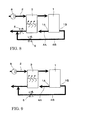
Figures 6-9 represent other four embodiments of the fuel cell system according to the present invention. It should be noted that parts of the same configuration as the previous embodiment, a detailed description thereof will be omitted by attaching the same reference numerals. - In the fuel cell system shown in
Fig. 6 , a flowrate control mechanism 5 is disposed in either a firstgas discharge passage 4A or secondgas discharge passage 4B. The diameter of flow passage in which the flowrate control mechanism 5 is disposed is larger than the diameter of flow passage of the other. - More specifically, in the fuel cell system shown, in a passage, i.e., in a first
gas discharge passage 4A is provided with a flowrate control mechanism 5, and the diameter of a passage, i.e., the firstgas discharge passage 4A is set larger than the diameter of the other passage, i.e., the secondgas discharge passage 4B (other passage) Thus, in this fuel cell system, a pressure loss of firstgas discharge passage 4A is lower than the pressure loss of the secondgas discharge passage 4B. - The fuel cell system shown in
Figure 7 has flowrate control mechanisms gas discharge passage 4A and the secondgas discharge passage 4B. The flow rate control mechanism provided in a first passage, i.e., firstgas discharge passage 4A, is a flowrate control valve 5 while the flowrate control mechanism 15 disposed in the secondgas discharge passage 4B is in the form of orifice. Therefore, in this fuel cell system, the pressure loss of the firstgas discharge passage 4A is lower than the pressure loss of the secondgas discharge passage 4B. - In the fuel cell system shown in
Fig. 8 , flowrate control mechanisms gas discharge passage 4A and the secondgas discharge passage 4B, and both flowrate control mechanisms - In the respective fuel cell systems shown in the above
Figs. 6 to 8 , similarly to the previous embodiment, by adjusting the opening degree of the flowrate control valve 5, the flow rate of discharge gas passing throughhumidifier 3 may be adjusted to control the humidification amount of the cathode gas. Moreover, in each fuel cell system, similarly to the previous embodiment, the distance betweenfuel cell 1 andhumidifier 3 may be shortend to realize the overall size of system configuration. - In particular, in the fuel cell system shown in
Figure 6 , use of a small diameter pipe for the secondgas discharge passage 4B may further contribute to miniaturization of the system structure. In addition, the fuel cell system shown inFig. 7 may be configure to set a desired ratio in pressure loss by using a common piping for the first and secondgas discharge passages orifice 15 appropriately. In addition, the fuel cell system shown inFig. 8 assures a even more accurate control of flow rate because of employment of flowrate control valves 5 in both the first and secondgas discharge passages - In each embodiment shown In
Figs. 1 to 8 , such a configuration has been proposed in which flow rate control mechanism is provided in the firstgas discharge passage 4A only, or flow rate control mechanisms are provided in both the first and secondgas discharge passages Fig. 9 , flowrate control valve 5 is disposed in the secondgas discharge passage 4B as a flow rate control mechanism. - , In this latter case, in the fuel cell system, contrary to the configurations in the previous embodiments, the pressure loss in the first
gas discharge passage 4A may be set lager than the pressure loss of the secondgas discharge passage 4B. For example, the diameter of the firstgas discharge passage 4A may be reduced, or anorifice 15 can be disposed in the firstgas discharge passage 4A. - Even in the fuel cell system above, by opening adjustment of flow
rate control valve 5, the flow rate of discharge gas passing throughhumidifier 3 may be adjusted and, similarly in the previous embodiments, by reducing the space betweenfuel cell 1 andhumidifier 3, a compact system structure may be realized. - Note that the fuel cell system is not confined to respective embodiments descried above, but an appropriate change in details of configurations may be available without departing from the scope of the present invention. Further, in the above embodiments, such a case has been explained in which
humidifier 3, first and secondgas discharge passages -
- 1
- Fuel cell
- 1A
- First gas outlet
- 1B
- Second gas outlet
- 2
- Gas supply path or passage
- 3
- Humidifier
- 4A
- First gas discharge passage
- 4B
- Second gas discharge passage
- 5
- Flow rate control valve (flow rate control mechanism)
- 15
- Orifice (flow rate control mechanism)
- C
- Unit cell
- S
- Fuel cell stack
Claims (8)
the reaction gas is cathode gas, and
the distance between the fuel cell stack and the humidifier is shorter that the diameter of the first gas discharge passage.
the flow rate control mechanism is provided in either the first gas discharge passage or second gas discharge passage; and
the pressure loss of a passage in which the flow rate control mechanism is provided is lower than the pressure los of the other passage.
the flow rate control mechanism is provided in either the first gas discharge passage or second gas discharge passage; and
the diameter of a passage in which the flow rate control mechanism is provided is larger than the diameter the other passage.
the flow rate control mechanism is provided in both the first gas discharge passage and second gas discharge passage; and
the flow rate control mechanism provided in the one passage is a flow rate control valve, and the flow rate control mechanism provided in the other passage is an orifice.
the flow rate control mechanism is provided in both the first gas discharge passage and second gas discharge passage; and
the flow rate control mechanism provided in the one passage is a flow rate control valve, and the flow rate control mechanism provided in the other passage is an orifice.
the flow rate control mechanism is provided in both the first gas discharge passage and second gas discharge passage; and
each flow rate control mechanism is a flow rate control valve.
Applications Claiming Priority (2)
| Application Number | Priority Date | Filing Date | Title |
|---|---|---|---|
| JP2010142242 | 2010-06-23 | ||
| PCT/JP2011/064101 WO2011162226A1 (en) | 2010-06-23 | 2011-06-21 | Fuel cell system |
Publications (2)
| Publication Number | Publication Date |
|---|---|
| EP2587577A1 true EP2587577A1 (en) | 2013-05-01 |
| EP2587577A4 EP2587577A4 (en) | 2015-08-26 |
Family
ID=45371409
Family Applications (1)
| Application Number | Title | Priority Date | Filing Date |
|---|---|---|---|
| EP11798110.0A Withdrawn EP2587577A4 (en) | 2010-06-23 | 2011-06-21 | Fuel cell system |
Country Status (5)
| Country | Link |
|---|---|
| US (1) | US20130137003A1 (en) |
| EP (1) | EP2587577A4 (en) |
| JP (1) | JP5505874B2 (en) |
| CN (1) | CN102986072B (en) |
| WO (1) | WO2011162226A1 (en) |
Families Citing this family (3)
| Publication number | Priority date | Publication date | Assignee | Title |
|---|---|---|---|---|
| DE102014210370A1 (en) * | 2014-06-02 | 2015-12-03 | Volkswagen Aktiengesellschaft | Humidifier, plate, device and motor vehicle |
| DE102014011136A1 (en) | 2014-07-25 | 2015-01-15 | Daimler Ag | Fuel cell system, vehicle and method for operating a fuel cell system |
| DE102015200935A1 (en) * | 2015-01-21 | 2016-07-21 | Volkswagen Aktiengesellschaft | Fuel cell system, vehicle with such and method for operating the fuel cell system and / or the vehicle |
Family Cites Families (13)
| Publication number | Priority date | Publication date | Assignee | Title |
|---|---|---|---|---|
| JPH0419965A (en) * | 1990-05-15 | 1992-01-23 | Ishikawajima Harima Heavy Ind Co Ltd | Molten carbonate fuel cell power generating unit |
| JPH09161819A (en) * | 1995-12-06 | 1997-06-20 | Fuji Electric Co Ltd | Solid polymer electrolyte fuel cell |
| JP3580236B2 (en) * | 2000-10-04 | 2004-10-20 | 日産自動車株式会社 | Fuel cell system |
| DE10157139A1 (en) * | 2001-11-21 | 2003-05-28 | Forschungszentrum Juelich Gmbh | Device for purifying waste gas in a direct-alcohol fuel cell or direct-alcohol fuel cell stack comprises a region containing a feed line and a removal line separated by a porous layer, and a catalyst on the surface of the porous layer |
| KR100534698B1 (en) * | 2003-07-11 | 2005-12-07 | 현대자동차주식회사 | Fuel cell system |
| US7875397B2 (en) * | 2003-12-15 | 2011-01-25 | Utc Power Corporation | Permeable inlet fuel gas distributor for fuel cells |
| US8071243B2 (en) * | 2005-12-02 | 2011-12-06 | Panasonic Corporation | Fuel cell system |
| JP4946087B2 (en) * | 2006-02-17 | 2012-06-06 | 株式会社日立製作所 | Fuel cell system |
| JP4695997B2 (en) * | 2006-02-28 | 2011-06-08 | 本田技研工業株式会社 | Fuel cell system |
| JP4687675B2 (en) * | 2007-03-28 | 2011-05-25 | 三菱電機株式会社 | Cross-flow blower and air conditioner |
| JP2008251188A (en) * | 2007-03-29 | 2008-10-16 | Toyota Motor Corp | Fuel cell stack |
| US20100003577A1 (en) * | 2008-07-04 | 2010-01-07 | Tohru Eguchi | Fuel gas supplying apparatus for fuel cell system |
| JP2010086853A (en) * | 2008-10-01 | 2010-04-15 | Honda Motor Co Ltd | Fuel cell system and its operation stop method |
-
2011
- 2011-06-21 CN CN201180030959.4A patent/CN102986072B/en not_active Expired - Fee Related
- 2011-06-21 US US13/805,807 patent/US20130137003A1/en not_active Abandoned
- 2011-06-21 EP EP11798110.0A patent/EP2587577A4/en not_active Withdrawn
- 2011-06-21 JP JP2012521470A patent/JP5505874B2/en not_active Expired - Fee Related
- 2011-06-21 WO PCT/JP2011/064101 patent/WO2011162226A1/en not_active Ceased
Also Published As
| Publication number | Publication date |
|---|---|
| CN102986072A (en) | 2013-03-20 |
| US20130137003A1 (en) | 2013-05-30 |
| CN102986072B (en) | 2015-03-04 |
| JP5505874B2 (en) | 2014-05-28 |
| EP2587577A4 (en) | 2015-08-26 |
| JPWO2011162226A1 (en) | 2013-08-22 |
| WO2011162226A1 (en) | 2011-12-29 |
Similar Documents
| Publication | Publication Date | Title |
|---|---|---|
| KR102751268B1 (en) | Humidifier for a fuel cell | |
| US11831047B2 (en) | Membrane humidifier for fuel cell, and fuel cell system comprising same | |
| US7923162B2 (en) | Fuel cell assemblies with integrated reactant-conditioning heat exchangers | |
| KR20210011204A (en) | Humidifier for fuel cell | |
| CN106935866A (en) | Bipolar plates for fuel cell and the fuel cell unit with the bipolar plates | |
| US7820333B2 (en) | Fuel cell operating method with improved hydrogen and oxygen utilization | |
| CN113823808B (en) | Fuel cell stack, system and application thereof | |
| US20120164559A1 (en) | Fuel cell and flow field plate for fluid distribution | |
| JP5642172B2 (en) | Operation method of fuel cell | |
| US20130137003A1 (en) | Fuel cell system | |
| KR102677163B1 (en) | Fuel cell membrane humidifier and fuel cell system comprising it | |
| US8507137B2 (en) | Separator plate configuration for a fuel cell | |
| JP3943006B2 (en) | Fuel supply device integrated structure | |
| JP2005166404A (en) | Fuel cell system | |
| CN118044017A (en) | Fuel cell stack module | |
| KR102923162B1 (en) | Air cooler and fuel cell system | |
| US20060134495A1 (en) | Fuel cell system with cathode stream recirculation | |
| JP2004047155A (en) | Fuel cell | |
| US20230378486A1 (en) | Bipolar plate with media regulation and fuel cell stack | |
| WO2025030474A1 (en) | End-plate member for fuel cell system, and fuel cell system | |
| JP2000164240A (en) | Fuel cell | |
| JP2005158544A (en) | Fuel cell system | |
| KR20250001271A (en) | Complex membrane humidifier for fuel cell | |
| KR20250152387A (en) | Fuel cell system | |
| KR20230071557A (en) | Fuel cell system |
Legal Events
| Date | Code | Title | Description |
|---|---|---|---|
| PUAI | Public reference made under article 153(3) epc to a published international application that has entered the european phase |
Free format text: ORIGINAL CODE: 0009012 |
|
| 17P | Request for examination filed |
Effective date: 20130103 |
|
| AK | Designated contracting states |
Kind code of ref document: A1 Designated state(s): AL AT BE BG CH CY CZ DE DK EE ES FI FR GB GR HR HU IE IS IT LI LT LU LV MC MK MT NL NO PL PT RO RS SE SI SK SM TR |
|
| DAX | Request for extension of the european patent (deleted) | ||
| RA4 | Supplementary search report drawn up and despatched (corrected) |
Effective date: 20150727 |
|
| RIC1 | Information provided on ipc code assigned before grant |
Ipc: H01M 8/04 20060101AFI20150721BHEP Ipc: H01M 8/10 20060101ALN20150721BHEP |
|
| RIC1 | Information provided on ipc code assigned before grant |
Ipc: H01M 8/04082 20160101ALI20160218BHEP Ipc: H01M 8/1018 20160101ALN20160218BHEP Ipc: H01M 8/04119 20160101AFI20160218BHEP Ipc: H01M 8/04746 20160101ALI20160218BHEP |
|
| GRAP | Despatch of communication of intention to grant a patent |
Free format text: ORIGINAL CODE: EPIDOSNIGR1 |
|
| INTG | Intention to grant announced |
Effective date: 20160329 |
|
| RIC1 | Information provided on ipc code assigned before grant |
Ipc: H01M 8/04746 20160101ALI20160314BHEP Ipc: H01M 8/04119 20160101AFI20160314BHEP Ipc: H01M 8/1018 20160101ALN20160314BHEP Ipc: H01M 8/04082 20160101ALI20160314BHEP |
|
| RIN1 | Information on inventor provided before grant (corrected) |
Inventor name: OSADA, TAKAHITO Inventor name: IKEZOE, KEIGO Inventor name: CHIKUGO, HAYATO |
|
| STAA | Information on the status of an ep patent application or granted ep patent |
Free format text: STATUS: THE APPLICATION IS DEEMED TO BE WITHDRAWN |
|
| 18D | Application deemed to be withdrawn |
Effective date: 20160809 |