EP2587410A2 - Communication device, system comprising a communication device, and communication method - Google Patents
Communication device, system comprising a communication device, and communication method Download PDFInfo
- Publication number
- EP2587410A2 EP2587410A2 EP13152746.7A EP13152746A EP2587410A2 EP 2587410 A2 EP2587410 A2 EP 2587410A2 EP 13152746 A EP13152746 A EP 13152746A EP 2587410 A2 EP2587410 A2 EP 2587410A2
- Authority
- EP
- European Patent Office
- Prior art keywords
- antenna
- section
- information
- optical disc
- disc
- Prior art date
- Legal status (The legal status is an assumption and is not a legal conclusion. Google has not performed a legal analysis and makes no representation as to the accuracy of the status listed.)
- Withdrawn
Links
- 238000000034 method Methods 0.000 title claims description 128
- 238000004891 communication Methods 0.000 title claims description 68
- 230000006854 communication Effects 0.000 title claims description 68
- 238000003860 storage Methods 0.000 claims description 10
- 238000012790 confirmation Methods 0.000 claims description 4
- 238000010295 mobile communication Methods 0.000 claims 16
- 230000010365 information processing Effects 0.000 claims 5
- 230000003287 optical effect Effects 0.000 abstract description 233
- 239000000758 substrate Substances 0.000 abstract description 163
- 230000005540 biological transmission Effects 0.000 abstract description 26
- 230000002093 peripheral effect Effects 0.000 abstract description 19
- 238000004519 manufacturing process Methods 0.000 abstract description 18
- 239000010410 layer Substances 0.000 description 79
- 239000010408 film Substances 0.000 description 45
- 238000012545 processing Methods 0.000 description 42
- 238000010586 diagram Methods 0.000 description 35
- 230000000694 effects Effects 0.000 description 28
- 238000004544 sputter deposition Methods 0.000 description 25
- 229910052751 metal Inorganic materials 0.000 description 24
- 239000002184 metal Substances 0.000 description 24
- 239000000853 adhesive Substances 0.000 description 23
- 230000001070 adhesive effect Effects 0.000 description 23
- 239000012790 adhesive layer Substances 0.000 description 22
- 230000004044 response Effects 0.000 description 21
- 239000003990 capacitor Substances 0.000 description 18
- 230000015572 biosynthetic process Effects 0.000 description 12
- 208000027418 Wounds and injury Diseases 0.000 description 10
- 239000004020 conductor Substances 0.000 description 10
- 238000001514 detection method Methods 0.000 description 9
- 230000035945 sensitivity Effects 0.000 description 9
- 238000004804 winding Methods 0.000 description 8
- 239000000203 mixture Substances 0.000 description 7
- 239000010409 thin film Substances 0.000 description 7
- 229920005989 resin Polymers 0.000 description 6
- 239000011347 resin Substances 0.000 description 6
- 229910001316 Ag alloy Inorganic materials 0.000 description 5
- 208000004221 Multiple Trauma Diseases 0.000 description 5
- 238000009713 electroplating Methods 0.000 description 5
- 230000007274 generation of a signal involved in cell-cell signaling Effects 0.000 description 5
- 229910000838 Al alloy Inorganic materials 0.000 description 4
- 230000007547 defect Effects 0.000 description 4
- 238000001746 injection moulding Methods 0.000 description 4
- 239000004065 semiconductor Substances 0.000 description 4
- 238000000926 separation method Methods 0.000 description 4
- 230000004913 activation Effects 0.000 description 3
- 230000003247 decreasing effect Effects 0.000 description 3
- 230000002950 deficient Effects 0.000 description 3
- 238000007772 electroless plating Methods 0.000 description 3
- 230000031700 light absorption Effects 0.000 description 3
- 230000000704 physical effect Effects 0.000 description 3
- 230000015556 catabolic process Effects 0.000 description 2
- 238000005520 cutting process Methods 0.000 description 2
- 230000007423 decrease Effects 0.000 description 2
- 238000006731 degradation reaction Methods 0.000 description 2
- 230000006866 deterioration Effects 0.000 description 2
- 230000005684 electric field Effects 0.000 description 2
- 239000007788 liquid Substances 0.000 description 2
- 229920000515 polycarbonate Polymers 0.000 description 2
- 239000004417 polycarbonate Substances 0.000 description 2
- 238000002360 preparation method Methods 0.000 description 2
- 238000003825 pressing Methods 0.000 description 2
- 238000007639 printing Methods 0.000 description 2
- 239000002356 single layer Substances 0.000 description 2
- 102100037812 Medium-wave-sensitive opsin 1 Human genes 0.000 description 1
- 238000009825 accumulation Methods 0.000 description 1
- 239000004840 adhesive resin Substances 0.000 description 1
- 229920006223 adhesive resin Polymers 0.000 description 1
- 229910052782 aluminium Inorganic materials 0.000 description 1
- XAGFODPZIPBFFR-UHFFFAOYSA-N aluminium Chemical compound [Al] XAGFODPZIPBFFR-UHFFFAOYSA-N 0.000 description 1
- 238000013459 approach Methods 0.000 description 1
- 230000007175 bidirectional communication Effects 0.000 description 1
- 238000006243 chemical reaction Methods 0.000 description 1
- 230000006378 damage Effects 0.000 description 1
- 230000003111 delayed effect Effects 0.000 description 1
- 238000013461 design Methods 0.000 description 1
- -1 dielectric Substances 0.000 description 1
- 239000008151 electrolyte solution Substances 0.000 description 1
- 230000007613 environmental effect Effects 0.000 description 1
- 238000001704 evaporation Methods 0.000 description 1
- 230000008020 evaporation Effects 0.000 description 1
- 230000005284 excitation Effects 0.000 description 1
- 238000010438 heat treatment Methods 0.000 description 1
- 238000002347 injection Methods 0.000 description 1
- 239000007924 injection Substances 0.000 description 1
- 239000012212 insulator Substances 0.000 description 1
- 238000007747 plating Methods 0.000 description 1
- 229910052709 silver Inorganic materials 0.000 description 1
- 238000002834 transmittance Methods 0.000 description 1
- 238000012795 verification Methods 0.000 description 1
Images


Classifications
-
- G—PHYSICS
- G11—INFORMATION STORAGE
- G11B—INFORMATION STORAGE BASED ON RELATIVE MOVEMENT BETWEEN RECORD CARRIER AND TRANSDUCER
- G11B7/00—Recording or reproducing by optical means, e.g. recording using a thermal beam of optical radiation by modifying optical properties or the physical structure, reproducing using an optical beam at lower power by sensing optical properties; Record carriers therefor
- G11B7/24—Record carriers characterised by shape, structure or physical properties, or by the selection of the material
- G11B7/24097—Structures for detection, control, recording operation or replay operation; Special shapes or structures for centering or eccentricity prevention; Arrangements for testing, inspecting or evaluating; Containers, cartridges or cassettes
-
- G—PHYSICS
- G06—COMPUTING; CALCULATING OR COUNTING
- G06K—GRAPHICAL DATA READING; PRESENTATION OF DATA; RECORD CARRIERS; HANDLING RECORD CARRIERS
- G06K19/00—Record carriers for use with machines and with at least a part designed to carry digital markings
- G06K19/04—Record carriers for use with machines and with at least a part designed to carry digital markings characterised by the shape
- G06K19/041—Constructional details
- G06K19/042—Constructional details the record carrier having a form factor of a credit card and including a small sized disc, e.g. a CD or DVD
- G06K19/044—Constructional details the record carrier having a form factor of a credit card and including a small sized disc, e.g. a CD or DVD comprising galvanic contacts for contacting an integrated circuit chip thereon
-
- G—PHYSICS
- G11—INFORMATION STORAGE
- G11B—INFORMATION STORAGE BASED ON RELATIVE MOVEMENT BETWEEN RECORD CARRIER AND TRANSDUCER
- G11B7/00—Recording or reproducing by optical means, e.g. recording using a thermal beam of optical radiation by modifying optical properties or the physical structure, reproducing using an optical beam at lower power by sensing optical properties; Record carriers therefor
- G11B7/24—Record carriers characterised by shape, structure or physical properties, or by the selection of the material
- G11B7/24094—Indication parts or information parts for identification
-
- G—PHYSICS
- G06—COMPUTING; CALCULATING OR COUNTING
- G06K—GRAPHICAL DATA READING; PRESENTATION OF DATA; RECORD CARRIERS; HANDLING RECORD CARRIERS
- G06K17/00—Methods or arrangements for effecting co-operative working between equipments covered by two or more of main groups G06K1/00 - G06K15/00, e.g. automatic card files incorporating conveying and reading operations
-
- G—PHYSICS
- G06—COMPUTING; CALCULATING OR COUNTING
- G06K—GRAPHICAL DATA READING; PRESENTATION OF DATA; RECORD CARRIERS; HANDLING RECORD CARRIERS
- G06K19/00—Record carriers for use with machines and with at least a part designed to carry digital markings
-
- G—PHYSICS
- G11—INFORMATION STORAGE
- G11B—INFORMATION STORAGE BASED ON RELATIVE MOVEMENT BETWEEN RECORD CARRIER AND TRANSDUCER
- G11B20/00—Signal processing not specific to the method of recording or reproducing; Circuits therefor
- G11B20/10—Digital recording or reproducing
-
- G—PHYSICS
- G11—INFORMATION STORAGE
- G11B—INFORMATION STORAGE BASED ON RELATIVE MOVEMENT BETWEEN RECORD CARRIER AND TRANSDUCER
- G11B23/00—Record carriers not specific to the method of recording or reproducing; Accessories, e.g. containers, specially adapted for co-operation with the recording or reproducing apparatus ; Intermediate mediums; Apparatus or processes specially adapted for their manufacture
- G11B23/0014—Record carriers not specific to the method of recording or reproducing; Accessories, e.g. containers, specially adapted for co-operation with the recording or reproducing apparatus ; Intermediate mediums; Apparatus or processes specially adapted for their manufacture record carriers not specifically of filamentary or web form
- G11B23/0021—Record carriers not specific to the method of recording or reproducing; Accessories, e.g. containers, specially adapted for co-operation with the recording or reproducing apparatus ; Intermediate mediums; Apparatus or processes specially adapted for their manufacture record carriers not specifically of filamentary or web form discs
- G11B23/0028—Details
- G11B23/0035—Details means incorporated in the disc, e.g. hub, to enable its guiding, loading or driving
- G11B23/0042—Details means incorporated in the disc, e.g. hub, to enable its guiding, loading or driving with provision for auxiliary features
-
- G—PHYSICS
- G11—INFORMATION STORAGE
- G11B—INFORMATION STORAGE BASED ON RELATIVE MOVEMENT BETWEEN RECORD CARRIER AND TRANSDUCER
- G11B23/00—Record carriers not specific to the method of recording or reproducing; Accessories, e.g. containers, specially adapted for co-operation with the recording or reproducing apparatus ; Intermediate mediums; Apparatus or processes specially adapted for their manufacture
- G11B23/28—Indicating or preventing prior or unauthorised use, e.g. cassettes with sealing or locking means, write-protect devices for discs
- G11B23/283—Security features, e.g. digital codes
- G11B23/284—Security features, e.g. digital codes on the record carrier
-
- G—PHYSICS
- G11—INFORMATION STORAGE
- G11B—INFORMATION STORAGE BASED ON RELATIVE MOVEMENT BETWEEN RECORD CARRIER AND TRANSDUCER
- G11B23/00—Record carriers not specific to the method of recording or reproducing; Accessories, e.g. containers, specially adapted for co-operation with the recording or reproducing apparatus ; Intermediate mediums; Apparatus or processes specially adapted for their manufacture
- G11B23/30—Record carriers not specific to the method of recording or reproducing; Accessories, e.g. containers, specially adapted for co-operation with the recording or reproducing apparatus ; Intermediate mediums; Apparatus or processes specially adapted for their manufacture with provision for auxiliary signals
-
- G—PHYSICS
- G11—INFORMATION STORAGE
- G11B—INFORMATION STORAGE BASED ON RELATIVE MOVEMENT BETWEEN RECORD CARRIER AND TRANSDUCER
- G11B27/00—Editing; Indexing; Addressing; Timing or synchronising; Monitoring; Measuring tape travel
- G11B27/10—Indexing; Addressing; Timing or synchronising; Measuring tape travel
- G11B27/11—Indexing; Addressing; Timing or synchronising; Measuring tape travel by using information not detectable on the record carrier
-
- H—ELECTRICITY
- H04—ELECTRIC COMMUNICATION TECHNIQUE
- H04N—PICTORIAL COMMUNICATION, e.g. TELEVISION
- H04N21/00—Selective content distribution, e.g. interactive television or video on demand [VOD]
- H04N21/40—Client devices specifically adapted for the reception of or interaction with content, e.g. set-top-box [STB]; Operations thereof
- H04N21/41—Structure of client; Structure of client peripherals
- H04N21/422—Input-only peripherals, i.e. input devices connected to specially adapted client devices, e.g. global positioning system [GPS]
- H04N21/42204—User interfaces specially adapted for controlling a client device through a remote control device; Remote control devices therefor
-
- H—ELECTRICITY
- H04—ELECTRIC COMMUNICATION TECHNIQUE
- H04N—PICTORIAL COMMUNICATION, e.g. TELEVISION
- H04N21/00—Selective content distribution, e.g. interactive television or video on demand [VOD]
- H04N21/40—Client devices specifically adapted for the reception of or interaction with content, e.g. set-top-box [STB]; Operations thereof
- H04N21/41—Structure of client; Structure of client peripherals
- H04N21/426—Internal components of the client ; Characteristics thereof
- H04N21/42646—Internal components of the client ; Characteristics thereof for reading from or writing on a non-volatile solid state storage medium, e.g. DVD, CD-ROM
-
- H—ELECTRICITY
- H04—ELECTRIC COMMUNICATION TECHNIQUE
- H04N—PICTORIAL COMMUNICATION, e.g. TELEVISION
- H04N5/00—Details of television systems
- H04N5/76—Television signal recording
- H04N5/84—Television signal recording using optical recording
- H04N5/85—Television signal recording using optical recording on discs or drums
-
- H—ELECTRICITY
- H04—ELECTRIC COMMUNICATION TECHNIQUE
- H04N—PICTORIAL COMMUNICATION, e.g. TELEVISION
- H04N9/00—Details of colour television systems
- H04N9/79—Processing of colour television signals in connection with recording
- H04N9/80—Transformation of the television signal for recording, e.g. modulation, frequency changing; Inverse transformation for playback
- H04N9/82—Transformation of the television signal for recording, e.g. modulation, frequency changing; Inverse transformation for playback the individual colour picture signal components being recorded simultaneously only
- H04N9/8205—Transformation of the television signal for recording, e.g. modulation, frequency changing; Inverse transformation for playback the individual colour picture signal components being recorded simultaneously only involving the multiplexing of an additional signal and the colour video signal
- H04N9/8233—Transformation of the television signal for recording, e.g. modulation, frequency changing; Inverse transformation for playback the individual colour picture signal components being recorded simultaneously only involving the multiplexing of an additional signal and the colour video signal the additional signal being a character code signal
-
- G—PHYSICS
- G11—INFORMATION STORAGE
- G11B—INFORMATION STORAGE BASED ON RELATIVE MOVEMENT BETWEEN RECORD CARRIER AND TRANSDUCER
- G11B20/00—Signal processing not specific to the method of recording or reproducing; Circuits therefor
- G11B20/00086—Circuits for prevention of unauthorised reproduction or copying, e.g. piracy
- G11B20/00094—Circuits for prevention of unauthorised reproduction or copying, e.g. piracy involving measures which result in a restriction to authorised record carriers
- G11B20/00115—Circuits for prevention of unauthorised reproduction or copying, e.g. piracy involving measures which result in a restriction to authorised record carriers wherein the record carrier stores a unique medium identifier
-
- G—PHYSICS
- G11—INFORMATION STORAGE
- G11B—INFORMATION STORAGE BASED ON RELATIVE MOVEMENT BETWEEN RECORD CARRIER AND TRANSDUCER
- G11B20/00—Signal processing not specific to the method of recording or reproducing; Circuits therefor
- G11B20/00086—Circuits for prevention of unauthorised reproduction or copying, e.g. piracy
- G11B20/00876—Circuits for prevention of unauthorised reproduction or copying, e.g. piracy wherein physical copy protection means are attached to the medium, e.g. holograms, sensors, or additional semiconductor circuitry
-
- G—PHYSICS
- G11—INFORMATION STORAGE
- G11B—INFORMATION STORAGE BASED ON RELATIVE MOVEMENT BETWEEN RECORD CARRIER AND TRANSDUCER
- G11B2220/00—Record carriers by type
- G11B2220/20—Disc-shaped record carriers
- G11B2220/25—Disc-shaped record carriers characterised in that the disc is based on a specific recording technology
- G11B2220/2537—Optical discs
- G11B2220/2562—DVDs [digital versatile discs]; Digital video discs; MMCDs; HDCDs
-
- G—PHYSICS
- G11—INFORMATION STORAGE
- G11B—INFORMATION STORAGE BASED ON RELATIVE MOVEMENT BETWEEN RECORD CARRIER AND TRANSDUCER
- G11B2220/00—Record carriers by type
- G11B2220/60—Solid state media
- G11B2220/65—Solid state media wherein solid state memory is used for storing indexing information or metadata
- G11B2220/652—Solid state media wherein solid state memory is used for storing indexing information or metadata said memory being attached to the recording medium
- G11B2220/657—Memory in disc [MID]
-
- H—ELECTRICITY
- H04—ELECTRIC COMMUNICATION TECHNIQUE
- H04N—PICTORIAL COMMUNICATION, e.g. TELEVISION
- H04N21/00—Selective content distribution, e.g. interactive television or video on demand [VOD]
- H04N21/40—Client devices specifically adapted for the reception of or interaction with content, e.g. set-top-box [STB]; Operations thereof
- H04N21/41—Structure of client; Structure of client peripherals
- H04N21/4104—Peripherals receiving signals from specially adapted client devices
- H04N21/4126—The peripheral being portable, e.g. PDAs or mobile phones
- H04N21/41265—The peripheral being portable, e.g. PDAs or mobile phones having a remote control device for bidirectional communication between the remote control device and client device
-
- H—ELECTRICITY
- H04—ELECTRIC COMMUNICATION TECHNIQUE
- H04N—PICTORIAL COMMUNICATION, e.g. TELEVISION
- H04N21/00—Selective content distribution, e.g. interactive television or video on demand [VOD]
- H04N21/40—Client devices specifically adapted for the reception of or interaction with content, e.g. set-top-box [STB]; Operations thereof
- H04N21/41—Structure of client; Structure of client peripherals
- H04N21/422—Input-only peripherals, i.e. input devices connected to specially adapted client devices, e.g. global positioning system [GPS]
- H04N21/42204—User interfaces specially adapted for controlling a client device through a remote control device; Remote control devices therefor
- H04N21/42206—User interfaces specially adapted for controlling a client device through a remote control device; Remote control devices therefor characterized by hardware details
- H04N21/42208—Display device provided on the remote control
- H04N21/42209—Display device provided on the remote control for displaying non-command information, e.g. electronic program guide [EPG], e-mail, messages or a second television channel
-
- H—ELECTRICITY
- H04—ELECTRIC COMMUNICATION TECHNIQUE
- H04N—PICTORIAL COMMUNICATION, e.g. TELEVISION
- H04N21/00—Selective content distribution, e.g. interactive television or video on demand [VOD]
- H04N21/40—Client devices specifically adapted for the reception of or interaction with content, e.g. set-top-box [STB]; Operations thereof
- H04N21/41—Structure of client; Structure of client peripherals
- H04N21/422—Input-only peripherals, i.e. input devices connected to specially adapted client devices, e.g. global positioning system [GPS]
- H04N21/42204—User interfaces specially adapted for controlling a client device through a remote control device; Remote control devices therefor
- H04N21/42206—User interfaces specially adapted for controlling a client device through a remote control device; Remote control devices therefor characterized by hardware details
- H04N21/4221—Dedicated function buttons, e.g. for the control of an EPG, subtitles, aspect ratio, picture-in-picture or teletext
-
- H—ELECTRICITY
- H04—ELECTRIC COMMUNICATION TECHNIQUE
- H04N—PICTORIAL COMMUNICATION, e.g. TELEVISION
- H04N21/00—Selective content distribution, e.g. interactive television or video on demand [VOD]
- H04N21/40—Client devices specifically adapted for the reception of or interaction with content, e.g. set-top-box [STB]; Operations thereof
- H04N21/41—Structure of client; Structure of client peripherals
- H04N21/422—Input-only peripherals, i.e. input devices connected to specially adapted client devices, e.g. global positioning system [GPS]
- H04N21/42204—User interfaces specially adapted for controlling a client device through a remote control device; Remote control devices therefor
- H04N21/42206—User interfaces specially adapted for controlling a client device through a remote control device; Remote control devices therefor characterized by hardware details
- H04N21/42222—Additional components integrated in the remote control device, e.g. timer, speaker, sensors for detecting position, direction or movement of the remote control, microphone or battery charging device
-
- H—ELECTRICITY
- H04—ELECTRIC COMMUNICATION TECHNIQUE
- H04N—PICTORIAL COMMUNICATION, e.g. TELEVISION
- H04N21/00—Selective content distribution, e.g. interactive television or video on demand [VOD]
- H04N21/40—Client devices specifically adapted for the reception of or interaction with content, e.g. set-top-box [STB]; Operations thereof
- H04N21/43—Processing of content or additional data, e.g. demultiplexing additional data from a digital video stream; Elementary client operations, e.g. monitoring of home network or synchronising decoder's clock; Client middleware
- H04N21/432—Content retrieval operation from a local storage medium, e.g. hard-disk
- H04N21/4325—Content retrieval operation from a local storage medium, e.g. hard-disk by playing back content from the storage medium
-
- H—ELECTRICITY
- H04—ELECTRIC COMMUNICATION TECHNIQUE
- H04N—PICTORIAL COMMUNICATION, e.g. TELEVISION
- H04N21/00—Selective content distribution, e.g. interactive television or video on demand [VOD]
- H04N21/40—Client devices specifically adapted for the reception of or interaction with content, e.g. set-top-box [STB]; Operations thereof
- H04N21/43—Processing of content or additional data, e.g. demultiplexing additional data from a digital video stream; Elementary client operations, e.g. monitoring of home network or synchronising decoder's clock; Client middleware
- H04N21/433—Content storage operation, e.g. storage operation in response to a pause request, caching operations
- H04N21/4334—Recording operations
Definitions
- the present invention relates to an optical disc and a remote control device.
- Portable-type optical discs are dispersed after recording of the contents due to their portability.
- the objective of the present invention is to provide an optical disc and a remote control device which enable searching for contents recorded on an optical disc by mounting an IC including ID information on an optical disc.
- a transmitting antenna and a receiving antenna are provided in an inner peripheral portion of an optical disc, and a transmission/reception IC which stores ID information of the optical disc is connected to the antennas.
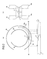
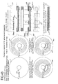
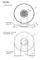
- Figure 1 is a diagram showing an example of a structure of an optical disc 1 according to an embodiment of the present invention.
- a transmitting antenna 2 and a receiving antenna 3 are provided in an inner peripheral portion of the optical disc 1.
- the transmitting antenna 2 and the receiving antenna 3 are formed along a circumferential direction of the optical disc 1 .
- the transmitting antenna 2 and the receiving antenna 3 are both dipole antennas.
- a transmission/reception IC 4 connected to the transmitting antenna 2 and the receiving antenna 3 is further provided.
- the transmission/reception IC 4 receives radio waves via the receiving antenna 3 and transmits radio waves via the transmitting antenna 2 .
- the transmission/reception IC 4 is formed on a chip.
- the chip is called an RFID chip.
- a hole 5 which allows the optical disc 1 to be attached to a rotation member for rotating the optical disc 1 is provided.
- an information layer 6 on which information can be recorded or from which information can be reproduced, is provided.
- the information layer 6 is formed between a substrate 7 and a transparent layer 8.
- An adhesive layer 9 is formed between the substrate 7 and the information layer 6.
- Figure 2(a) is an enlarged view of a portion around the transmitting antenna 2 and the receiving antenna 3 shown in Figure 1 .
- the transmitting antenna 2 includes transmitting antenna portions 2a and 2b.
- the receiving antenna 3 includes receiving antenna portions 3a and 3b.
- the transmitting antenna portions 2a and 2b are arranged so as to have an orientation shifted by 90° from an orientation of the receiving antenna portions 3a and 3b.
- Figure 2(b) is a portion around the transmission/reception IC 4 shown in Figure 1 .
- the receiving antenna portions 3a and 3b are connected to the transmission/reception IC 4 via a relay substrate 11.
- the transmitting antenna portions 2a and 2b are connected to the transmission/reception IC 4 via wiring 10a and 10b and the relay substrate 11.
- the wiring 10a extends the transmitting antenna portion 2a.
- the wiring 10b extends the transmitting antenna portion 2b.
- the wiring 10a and 10b are parallel to each other.
- the recording/reproduction apparatus is an apparatus which performs at least one of a recording operation for recording information on the optical disc 1 and a reproduction operation for reproducing information recorded on the optical disc 1.
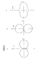
- Figure 3(a) shows a directivity of a dipole antenna A. It is shown that the antenna A is not sensitive in a longitudinal direction of dipoles of the antenna A (i.e., y direction).
- Figure 3(b) shows a directivity of a dipole antenna B shifted by 90° with respect to the dipole antenna A. It is shown that the antenna B is not sensitive in a longitudinal direction of dipoles of the antenna B (i.e., x direction).
- Figure 3(c) shows a directivity of an antenna in the case in which the dipole antenna A and the dipole antenna B are arranged in combination.
- the dipole antenna B is arranged so as to be shifted by 90° with respect to the dipole antenna A. It is shown that an antenna which is sensitive in all directions can be implemented by arranging the antennas A and B such that a dead zone of the antenna A and a dead zone of the antenna B are orthogonal to each other.
- the transmitting antenna 2 ( Figure 1 ) and the receiving antenna 3 ( Figure 1 ) are arranged so that the dead zone of the transmitting antenna 2 and the dead zone of the receiving antenna 3 are orthogonal to each other.
- an antenna which is sensitive in all directions can be implemented.
- ID information (RFID) stored in the transmission/reception IC 4 of the optical disc 1 can be detected.
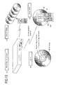
- Figure 4(a) shows another example of the structure of the optical disc 1 according to an embodiment of the present invention.
- a loop-type antenna is used instead of a dipole antenna.
- a transmitting antenna 2 and a receiving antenna 3 are provided in an inner peripheral portion of the optical disc 1 .
- the transmitting antenna 2 and the receiving antenna 3 are formed along a circumferential direction of the optical disc 1.
- the transmitting antenna 2 and the receiving antenna 3 are both loop antennas.
- the receiving antenna 3 is positioned such than it is closer to the outer periphery compared to the receiving antenna 2.
- a transmission/reception IC 4 connected to the transmitting antenna 2 and the receiving antenna 3 is further provided (see Figure 4(b) ).
- the transmission/reception IC 4 receives radio waves via the receiving antenna 3 and transmits radio waves via the transmitting antenna 2.
- Figure 4(b) is an enlarged view of portion A shown in Figure 4(a) .
- Terminals 2a and 2b of the transmitting antenna 2 and terminals 3a and 3b of the receiving antenna 3 are connected to the transmission/reception IC 4 via a relay substrate 11.
- an antenna formed along a circumferential direction of an optical disc 1 and an optical disc 1 including a transmission/reception IC 4 for transmitting/receiving radio waves via the antennas are within the scope of the present invention.
- An antenna which is formed on the optical disc 1 is not limited to the above-mentioned two-types of antennas (i.e., dipole antenna and loop antenna).
- Figure 5 shows an appearance of the optical disc 1, a remote control 15, a recording/reproduction apparatus 35 and a display portion 100.
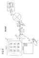
- Figure 6 shows an example of the structure of the optical disc 1, remote control 15 and recording/reproduction apparatus 35.
- radio waves having a particular frequency radiate from a transmitting section 17 and a transmitting antenna 18 to the optical disc 1, as indicated by an arrow 19a.
- a particular frequency for example, 2.45 GHz
- Such radio waves are received by the receiving antenna 3 of the optical disc 1 and detected by a detection section 21 of a receiving circuit 20.
- power 22 and a signal are obtained.
- the power 22 is sent to a signal generation section 23 and temporarily accumulated in a power accumulation section 24 such as a capacitor or the like. This feeble power is used to read out ID 25 in an ID number storage section 26.
- An ID number generation section 27 and a modulation section 28 generate a modulation signal including the ID number.
- the modulation signal is delayed by a time period corresponding to a time constant 30 by a time adjusting section 29.
- the time constant 30 is preset when the transmission/reception ICs 4 is fabricated such that every transmission/reception ICs 4 has a different time constant 30.
- the ID 25 is information for identifying the optical disc 1.
- the ID 25 is also called ID information.
- the ID 25 is not limited to a number (it may be a combination of alphanumeric characters, symbols and the like).
- the signal generation section 23 generates a signal including ID information in response to a signal output from the receiving circuit (receiving section) 20.
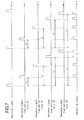
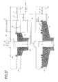
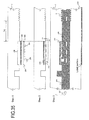
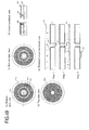
- Figure 7 shows an example of waveforms of a reception signal received from the remote control 15, response signals from a plurality of optical discs 1 (#1-#4) responding to the reception signal, and a detection signal detected by the remote control 15.
- the optical discs #1, #2, #3, and #4 have different response times t 1 , t 2 , t 3 and t 4 to the reception signal from the remote control 15. This is because the time constants 30 in the transmission/reception ICs 4 mounted on the optical discs #1 through #4 are different from each other. Thus, waveforms of the response signals from the optical discs #1 through #4 are different as shown in Figure 7 .
- the waveform of the detection signal detected by the remote control 15 is as shown in Figure 7 .
- the response signals from the optical discs #1 through #4 are separated in a time-wise manner from each other.
- the remote control 15 can separate signals transmitted from a plurality of optical discs 1 in a time-wise manner and detect them. In this way, collision of the response signals from a plurality of optical discs 1 can be prevented.
- the response signals from a plurality of optical discs 1 are separated in a time-wise manner by time separation means 32 ( Figure 6 ).
- time separation means 32 Figure 6
- IDs of the optical discs 1 can be identified stably.
- a random number generation section 34 for generating time constants at random may be provided to achieve similar effects.
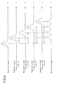
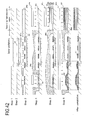
- Figure 8 shows another example of waveforms of a reception signal received from the remote control 15, response signals from a plurality of the optical discs 1 (#1-#4) responding to the reception signal, and a detection signal detected by the remote control 15.
- the optical discs #1, #2, #3, and #4 have response signals having different amounts of shifts f 1 , f 2 , f 3 and f 4 in central frequencies from that of the reception signal from the remote control 15 (for example, an excitation signal having a particular central frequency). This is because the frequencies set by frequency setting sections 31 in the transmission/reception ICs 4 mounted on the optical discs #1 through #4 are different from each other. Thus, waveforms of the response signals from the optical discs #1 through #4 are different as shown in Figure 8 .
- the waveform of the detection signal detected by the remote control 15 is as shown in Figure 8 .
- the response signals from the optical discs #1 through #4 are separated from each other with respect to the frequencies.
- the remote control 15 can separate signals transmitted from a plurality of optical discs 1 with respect to the frequencies and detect them. In this way, collision of the response signals from a plurality of optical discs 1 can be prevented.
- the response signals from a plurality of optical discs 1 are separated with respect to the frequencies by frequency separation means 33 ( Figure 6 ).
- IDs of the optical discs 1 can be identified stably even within one time zone.
- the number of optical discs 1 which respond to the reception signal is not limited to four. N number of optical discs 1 may respond to the reception signal.
- n is any integer of 1 or greater.
- the time adjusting section 29 and the frequency setting section 31 are both included in the signal generation section 23.
- the signal generation section 23 may include only one of the time adjusting section 29 and the frequency setting section 31. In this case, it is sufficient if only one of the time separation means 32 and the frequency separation means 33 is included in the receiving section of the remote control 15.
- ID reproduction section 36 receives a reception signal including ID and generates ID information 37.
- the ID information 37 is output to a processing section 38.
- the processing section 38 displays the ID information 37 on a display portion 39 of the remote control 15 and transmits the ID information 37 to a receiving section 44 of a communication section 41 of the recording/reproduction apparatus 35 from a transmitting section 42 of a communication section 40.
- a method of communication between the communication section 40 and the communication section 41 may be an optical communication or may be a radio communication.
- a light emitting portion for transmitting a remote control signal which is normally equipped to the remote control 15 may also serve as the transmitting section 42 and a light receiving portion for receiving the remote control signal which is usually equipped to the recording/reproduction apparatus 35 may also serve as the receiving section 44.
- a transmitting section 42 and a receiving section 44 it is not necessary to additionally provide a transmitting section 42 and a receiving section 44.
- a set of a transmitting/receiving unit (light receiving/emitting unit) can be omitted.
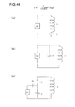
- bidirectional communication can be performed between the communication section 40 and the communication section 41 by providing a transmitting antenna 46 and a receiving antenna 47 in the communication section 40, providing a transmitting antenna 49 and a receiving antenna 48 in the communication section 41, and using Bluetooth using radio waves of frequency 2.4 GHz or local area wireless network such as IEEE 802.11b.
- a transmitting antenna 46 of the remote control 15 may also serve as the transmitting antenna 18 and a receiving antenna 47 may also serve as the receiving antenna 50.
- a set of transmitting/receiving antennas can be omitted.
- the receiving section 44 of the communication section 41 outputs the received ID information 37 to the processing section 51.
- a search section 52 searches a disc information file 53 and obtains disc physical property information 54, disc logic information 55 or the like corresponding to the ID information 37.
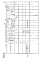
- Figure 9 shows an example of the data structure of the disc information file 53.
- ID information 37 is data equal to or greater than 100 bits (for example, data of 128 bits).
- disc management number 57 for example, "04"
- a virtual ID having a data amount smaller than that of the ID information 37, it becomes possible to manage IDs with smaller amount of data.
- the disc information file 53 includes the disc physical property information 54 and the disc logic information 55 for each ID.
- the disc physical property information 54 includes data indicating a total storage capacity 58 of the disc, a remaining capacity 59 of the disc, disc type 60 (such as rewritable type, write-once type, or ROM), the number of layers 61 of the disc (single layer or double layer) and the like.
- the disc logic information 55 includes information regarding a program recorded on the disc (program information 70).
- the program information 70 includes property data of the program, information regarding contents, thumbnails of the contents and the like.
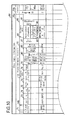
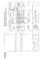
- Figure 10 shows program information 70a and 70b as examples of the program information 70 in the disc logic information 55.
- the program information 70a indicates program information of program 1.
- the program information 70a includes a program ID 71, property data 72, and contents data 86.
- the property data 72 includes a start address 73, an end address 74, total recording time 75, an ID of the program coming after the current program (program ID of link destination) 76, time to start and finish recording (recording time) 77, a recording source or a TV channel number 78, a program title 79, property information of the contents of the program 80 (a category of the program 81, a name of the characters appearing in the program 82, an area 83, program contents 84 and the like). Furthermore, in the case of a program linked to a web site, the property data 72 further includes an address of a web site of a link destination (URL) 85.
- URL link destination
- the contents data 86 includes a still picture 87 (for example, a still picture in JPEG format or the like of the first scene of program 1) and motion picture data 88 for first few seconds (a low-resolution motion picture 89 in MPEG 4 format or the like and a representative screen (thumbnail) of a high-resolution motion picture 90 at a high rate in MPEG 2 format or the like.
- the contents data 86 may include thumbnail data 91 which is a collection of the thumbnails.
- step 95a the recording/reproduction apparatus 35 waits to obtain the ID information that is to be sent from the remote control 15.
- step 95b the recording/reproduction apparatus 35 obtains new ID information which is different from the current ID information it has.
- step 95c the processing section 51 defines the new ID information as the n-th ID information (i.e., ID(n)).
- step 95d the processing section 51 searches the disc information file 53 ( Figures 9 and 10 ) using the search section 52.
- step 95e the processing section 51 determines whether there is data regarding ID(n) in the disc information file 53.
- step 95j the processing section 51 reads out image data (motion picture data 89 and 90, still picture data 87, or thumbnail data 91 ( Figure 10 )) of m-th program information 72 (program m) corresponding ID(n) from the disc information file 53 by using the search section 52.
- step 95k the processing section 51 transmits image data to the remote control 15 via the communication channel (a transmitting section 45 and the transmitting antenna 49).
- step 95m the receiving section 43 of the remote control 15 receives the image data.
- step 95n the processing section 38 extends the received image data using an image decoder 100 and displays the extended image data in the display portion 39 ( Figure 13(d)) . In this way, motion picture or still picture of thumbnails of data of contents recorded in the optical disc 1 can be confirmed by only bringing the remote control 15 close to the optical disc 1, without attaching the optical disc 1 to the recording/reproduction apparatus 35.
- step 95p the processing section 38 determines whether the display of the image data is completed or not and continues displaying the image data until the display of the image data is completed.
- step 95q the processing section 38 continues displaying the image data until a next new image display request arrives, or until a certain amount of time has elapsed.
- the next new image display request may be issued by, for example, a user pressing a next screen button 101 of the remote control 15 ( Figure 5 ). If there is a next new image display request, it is determined "Yes" in step 95q, and the process proceeds to step 95y. In step 95y, it is determined whether m is the last or not. If m is not the last, the process proceeds to step 95h. In step 95h, m is incremented by 1. In step 95j, the processing section 38 displays the next new image on the display portion 39.
- motion picture data is sent from the recording/reproduction apparatus 35 (server) to the remote control 15.
- the processing section 51 reads out motion picture data showing a thumbnail of program 1 (for example, motion picture data for the first 5 seconds of program 1) from the disc information file 53 and sends it to the remote control 15.
- the motion picture data is, for example, low-resolution motion picture data 89 of MPEG 4 grade.
- the processing section 38 receives the motion picture data and displays it on the displaying portion 39 ( Figure 13(d) ) .
- the processing section 51 When the user presses the next screen button 101 of the remote control 15, the processing section 51 reads out motion picture data showing a thumbnail of program 2 (for example, motion picture data for the first 5 seconds of program 2) from the disc information file 53 and sends it to the remote control 15.
- the processing section 38 receives motion picture data and displays it on the displaying portion 39 ( Figure 13(d) ).
- step 95q in the case where the next image display request is issued, or a previous screen display request is issued by the user pressing a previous screen button 102 of the remote control 15, if m is the last in step 95y, the process returns to the first step 95a and the recording/reproduction apparatus 35 waits to obtain the next ID information. Thereafter, the same operation as described above is performed.
- normal quality images and low resolution motion picture 89 are both recorded in the disc information file 53.
- only normal quality images may be recorded in the disc information file 53.
- rate conversion for a normal quality image for example, MPEG2 image of 6 Mbps
- the low-resolution motion picture 89 for example, MPEG 4 image of 384 kbps
- the low-resolution motion picture 89 may be sent to the remote control 15.
- step 95f the process proceeds to steps 96a through 96c shown in Figure 12 . If it is determined “No” in step 96c, the process proceeds to step 96d.
- step 96d the processing section 51 reads out the property data 72 of m-th program information 72 (program m) corresponding to ID (n) using the search section 52, and, in step 96e, transmits it through a communication path and finally to the remote control 15.
- step 96f the receiving section 43 of the remote control 15 receives the property data.
- step 96g the processing section 38 displays the property data (for example, remaining capacity) or the program list on the display portion 39. When the program list is displayed on the display portion 39, if the user presses a down key 104 of the remote control 15 ( Figure 14 ), the program in a downward direction in the screen is selected.
- the user may (1) bring the remote control 15 close to the optical disc 1 and (2) press a view button 16 of the remote control 15.
- the remote control 15 (3) reads out the ID of the optical disc 1 and (4) transmits the ID read by the remote control 15 to the recording/reproduction apparatus 35.
- the recording/reproduction apparatus 35 (5) searches the database to obtain the program list data and (6) sends the program list data to the remote control 15.
- the program list is displayed on the display portion 39 of the remote control 15.
- the user presses the down key 104 of the remote control 15 (7) the program in a downward direction is selected.
- step 96h the processing section 38 determines whether or not displaying the property data or the program list is completed and continues displaying the property data or the program list until displaying the property data or the program list is completed ( Figure 14 ).
- step 96i the processing section 38 determines whether the program list is displayed on the display portion 39. If it is determined “Yes” in step 96i, in step 96k, the processing section 38 determines whether any of the scroll buttons 101 through 104 ( Figure 14 ) is pressed or not. If it is determined “Yes” in step 96k, in step 96m, the processing section 38 changes a program mark in the program list.
- step 96p the processing section 38 determines whether it is possible to display the image. If it is determined “Yes” in step 96p, in step 96q, the processing section 38 displays a thumbnail image, motion picture, or still picture of the selected program on the display portion 39. In step 96r, the processing section 38 determines whether or not the program list is completed. If it is determined “Yes” in step 96r, the process proceeds to step 96j. If it is determined “No” in step 96p (i.e., if the image cannot be displayed), the process proceeds to step 96s.
- step 96s the processing section 38 displays the detailed property data of the marked program on the display portion 39.
- the property data is read from the disc information file 53, sent to the remote control 15, and displayed on the display portion 39 of the remote control 15.
- the property data includes, for example, category 81, name 82, area 83 and contents 84 of the program, billing identifier 85a which indicates whether or not viewing the program requires payment, and link destination address 85 which indicates an address or URL of a website for decoding and billing.
- step 96f the processing section 38 determines whether the program list is completed. If it is determined "Yes" in step 96f, the process proceeds to step 96j.
- step 96j the processing section 38 determines whether there is a request for displaying the next property data. If it is determined "Yes” in step 96j, the process returns to step 96b, and the operation of incrementing m by 1, reading out the m-th property data from the disc information file 53, and displaying the read out property data on the display portion 39 is repeated.
- step 95r the processing section 51 determines whether or not it is possible to connect to other machines or servers. If it is determined “No” in step 95r, the process proceeds to step 95u. In step 95u, the processing section 51 sends a message of "No data" or information indicating the message to the remote control 15 via the communication channel and displays the message or the information indicating the message on the display portion 39. If it is determined “Yes” in step 95r, in step 95s, the processing section 51 connects to another submachine 35a via the communication section 41, a communication channel 283 and a communication section 41a.
- the communication channel 283 may be wired or wireless, or may be the internet 284 as shown in Figure 6 .
- a processing section 51a of the submachine 35a searches a disc information file 53.
- the processing section 51a determines whether the disc information file includes the data corresponding to ID (n). If it is determined “Yes” in step 95t, the process proceeds to step 95v.
- the processing section 51 determines whether the remote control 15 has a capability to display the image, or there is an image display request from the remote control 15. If it is determined "Yes” in step 95v, in step 95w, the processing section 51 reads out the image data corresponding to ID (n) from the disc information file 53.
- step 95x the processing section 51 sends the read out image data to the master machine (i.e., the recording/reproduction apparatus 35 in Figure 6 ) via the communication section 41a, the communication channel 283 and the communication section 41. Then, the process returns to step 95k.
- the master machine i.e., the recording/reproduction apparatus 35 in Figure 6
- step 95v If it is determined "No” in step 95v (i.e., if the remote control 15 cannot display the image), the process proceeds to step 96j of Figure 12 , the processing section 51 reads out m-th property data corresponding to ID(n) from the disc information file 53.
- step 95k the processing section 51 sends the read out property data to the master machine (i.e., the recording/reproduction apparatus 35 in Figure 6 ) via the communication section 41a, the communication channel 283 and the communication section 41. Then, the process proceeds to step 96e.
- step 96e the property data is finally sent to the remote control 15 from the master machine. Finally, the property data is displayed on the display portion 39 of the remote control 15.
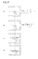
- a main unit antenna 110 is provided near a tray 113 in which the optical disc 1 is set.
- a tray antenna 112 is provided inside the tray 113.
- the main unit antenna 110 transmits radio waves periodically or when the tray 113 is slid out (step 111a).
- ID information of the optical disc 1 is read out by radio waves transmitted from the main unit antenna 110. It is determined whether reading out the ID information of the optical disc 1 is completed (step 111c).
- the set signal is turned ON (step 111d).
- the tray antenna 112 transmits radio waves (step 111e).
- the ID information of the optical disc 1 is read out. It is determined whether reading out the ID information of the optical disc 1 is completed (step 111f).
- the reproduction or recording can be started using data in the disc information file 53 in the recording/reproduction apparatus 35.
- the tray 113 is stored as shown in Figure 17 (step 111g), and the optical disc 1 is attached to a rotation motor member 121. Rotation of the optical disc 1 is started (step 111h).
- bar codes 114 are formed circumferentially.
- the bar codes 114 record ID numbers which are different for every optical disc 1.
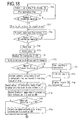
- BCA information which corresponds to the ID information stored in the transmission/reception IC 4 to be mounted on the optical disc 1 (hereinafter, referred to as the ID information of the IC), is recorded in the BCA.
- BCA information same as the ID information of the IC may be included.
- ID information included in BCA information is referred to as ID information of the BCA.
- ID information of the BCA In the normal optical disc 1, the ID information of the IC and the ID information of the BCA match.
- the recording/reproduction apparatus 35 reads out the ID information of the BCA (step 111j), verifies the ID information of the BCA and the ID information of the IC (step 111j), and determines whether they match or have a particular relationship (step 111k). If it is determined "No" in step 111k, the recording/reproduction apparatus 35 regards the optical disc 1 as an invalid disc and stops recording or reproduction (step 111m).
- the tray 113 is slid out (step 111n), and "Invalid ID information" is displayed on a display potion 151 ( Figure 21 ) (step 111p). In this way, invalid use of a disc such as an unauthorized duplication, an unauthorized reproduction and the like can be prevented.
- the ID information 37 read from the optical disc 1 by radio waves and optical ID information 115 optically read from the BCA are recorded in the disc information file 53 as shown in Figure 9 .
- Media ID 116 and a cryptographic key block 117 are recorded in the disc information file 53 as shown in Figure 9 (step 111q).
- a key which is suitable for the machine is selected from the cryptographic key block 117 which is called MKB (Media Key Block) for copyright protection which limits duplication over multiple generations, and encodes the contents or the information corresponding the contents using the cryptographic key and the media ID 116 corresponding to the optical ID information 115 to record in the recording region of the optical disc 1 (step 111r).
- MKB Media Key Block
- a still picture image encoder 131 compresses the first still picture of each scene in the contents input from an input section 130.
- a thumbnail processing section 135 records still pictures compressed by the still picture image encoder 131 in the disc information file 53.
- a low-definition image encoder 132 creates thumbnails of low-definition image such as MPEG 4 based on contents input from the input section 130 for a particular amount of time (for example, 20 seconds).
- the thumbnail processing section 135 records thumbnails of low-definition image created by the low-definition image encoder 132 in the disc information file 53.
- a normal quality image is compressed by an image encoder 133 and recorded in the disc information file 53. If it is determined that a copyright protection flag is ON in step 111t, contents encrypted by an encryption encoder 134 is recorded in the disc information file 53 (step 111u).
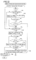
- step 119a when an optical disc 1 is brought close to the tray 113, detection signal is ON because an approach sensor 150 is provided in front of the tray 113 as shown in Figures 15 and 21 .
- step 119b the antenna 110 transmits radio waves for detection.
- step 119c a response signal including the ID information is sent back from the optical disc 1. Thus, reading out the ID information is completed.
- step 119d when the optical disc 1 is set in the tray 113, a set signal is ON and the antenna 112 transmits radio waves to the optical disc 1 (step 119e).
- step 119g the ID information or the property information of the optical disc 1 (for example, the remaining capacity of the optical disc 1) is displayed on the display portion 151. If it is determined that there is a disc information file 53 regarding the optical disc 1 in step 119o, a latency time for reproduction or recording can be reduced. If it is determined that reproduction start button is pressed in step 119h, the tray 113 is stored and the optical disc 1 is rotated (step 119j). In step 119k, the media ID, the cryptographic key block such as MKB and the like are read out from the disc information file 53 recorded in the recording/reproduction apparatus 35.
- step 119m contents information recorded in HDD or the like in the recording/reproduction apparatus 35 is read out.
- the process proceeds to step 119p, and a cryptographic key for decoding is created by using the media ID and cryptographic key block to obtain plaintext by decoding the encrypted contents.
- step 119q the plaintext is decoded by an AV decoder to output a digital audiovisual signal. The data is read out from the contents recording section of the disc information file.
- step 119r the tray 113 is stored and the reproduction of the optical disc 1 is started.
- the optical ID information of the optical disc 1 is optically read out from the optical disc 1, and, in step 119t, it is verified whether the optical ID information and the radio wave ID information match or have a particular relationship. If it is determined "No" in step 119t, the optical ID information is given a higher priority, and, if there is a disc information file corresponding to the optical ID information, a thumbnail therein is output. If there is no disc information file corresponding to the optical ID information, the process is held until a signal from the optical disc 1 is obtained (step 119u).
- step 119v it is determined whether the reproduction of the optical disc 1 is started.
- step 119w it is prepared for the switching an output signal from the signal read out from the disc information file to the reproduction signal from the optical disc 1. Switching of the output signal is performed so that a time stamp of the signal read out from the disc information file matches a time stamp of the reproduction signal from the optical disc 1.
- step 119x the output signal is switched at the same time and at an interval of GOPs (step 119y) .
- the reproduction is started in a normal reproduction mode (step 119z).
- step 119h in Figure 19 If it is determined “No” in step 119h in Figure 19 (i.e., when the reproduction start button is not pressed), it is determined whether a recording start button is pressed in step 119i. If it is determined “Yes” in step 119i, the process proceeds to step 120 of Figure 20 .
- step 120 it is determined whether the optical disc 1 has been recorded one time or more, and thus, the disc information file has already been obtained. If it is determined “Yes” in step 120, in step 120a, a procedure of storing the tray 113 and recording to the optical disc 1 is started. In step 120b, the media ID and the cryptographic key block corresponding to the ID is read out from the disc information file. In step 120c, coded information, which is coded contents information, is encrypted using the media ID and the cryptographic key block read out from the disc information file to create a code. In step 120d, the code is temporarily recorded in a memory other than the optical disc, such as an IC.
- the code is recorded in an IC or HDD during a preparation time (normally, 30 seconds to 1 minute) for recording to the optical disc 1.
- the ID information of the optical disc 1 (referred to as optical ID information) is optically read.
- step 120f it is determined whether the optical ID information and the radio wave ID information matches or have a particular relationship. If it is determined "No" in step 120f, the process proceeds to step 120g and the optical ID information is used in precedence. The tray 113 is slid out and the radio wave ID information is read out again. Then, the optical ID information and radio wave ID information are verified.
- step 120f it is determined whether preparation for recording to the optical disc is finished or not in step 120h. If it is determined “Yes” in step 120h, the rotational velocity of the optical disc 1 is set to be double-speed or higher in step 120i. In step 120j, the code recorded in a memory such as an IC or the like is recorded to the optical disc 1 from the start time.
- step 120k an image for a certain amount of time or a still picture of low-definition coded information which is contents coded at a bit rate lower than that for the above coded information is recorded in the disc information file as a thumbnail.
- step 120m when the recording rate to the optical disc 1 is S R and the rate of input signal is S I , recording is performed for a certain amount of time with S R >S I maintained.
- step 120n time information t R of the contents currently recorded in the optical disc 1 and time information t I of the contents which are currently being input are compared. If t I >t R in step 120p, the process returns to step 120m.
- step 120q the contents are directly recorded to the optical disc 1.
- step 120r when recording rate of the optical disc is S R and the rate of the input signal is S I , S R ⁇ S I . Then, normal recording is performed in step 120s.
- step 135a of Figure 22 property information of the contents is input. Physical information such as a disc capacity, a remaining capacity and the like, and property information of the contents such as a name of an actor featured in the program, trade name, place name and the like.
- step 135b the disc information file is searched using the property information of the input contents as keywords. If the ID corresponding to the property information of the contents is located in step 135c, it is determined whether the optical disc of the ID is the desired optical disc in step 135d. If it is determined “Yes" in step 135d (i.e., when the optical disc of the ID is the desired disc), the process proceeds to step 135k and a termination process is performed.
- step 135d the property information of the disc (for example, remaining capacity or the like) is input in step 135e.
- step 135f the input property information of the disc is used as keywords to search the disc information file. If the ID corresponding to the property information of the disc is located in step 135g, it is determined whether the optical disc of the ID is the desired disc in step 135h. If it is determined “Yes” in step 135g, the process proceeds to step 135k and the termination process is performed. If it is determined “No” in step 135g, the process proceeds to step 135i and access to other machines (for example, a server connected to a network) is made using the communication means and the disc information file is searched.
- other machines for example, a server connected to a network
- step 135j if the corresponding ID is located in step 135j, the process proceeds to step 135k and the corresponding ID is displayed on the display portion of the recording/reproduction apparatus and the display portion of the remote control. If it is determined "No" in step 135j, the process proceeds to step 135m and the display portion displays that there is no corresponding ID. Then, the process ends.
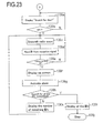
- the ID number of the optical disc to be searched for is specified in step 135k. Next, a method for searching for an optical disc having a specified ID number will be described.
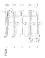
- step 136a a question "Search for disc?" is displayed on the display portion.
- radio waves for a search are transmitted in step 136c.
- the radio waves for a search are transmitted from transmitting antennas 18a, 18b, and 18c in three directions in a time-division manner.
- response signals from optical discs are time-divided into time slots A, B and C, and thus, they can be readily separated.
- IDs are read from each of the reception signals 139a, 139b in step 136d, and determined whether each of them is a corresponding ID or not in step 136e. If there is a corresponding ID, the corresponding ID is displayed in step 136f.
- an arrow 140a is displayed on the displaying portion 39 of the remote control 15. The arrow 140a indicates that the optical disc which is being searched for is in the direction of the arrow.
- An alarm sound is activated in step 136g. The alarm sound may be activated at the same time as displaying the corresponding ID in step 136f.
- step 136h it is determined whether the search for all the optical discs which are being searched for is completed.
- step 136i If it is determined that the search has been completed, all the IDs are displayed (step 136i) and the process stops (step 136j). If it is determined that the search is not completed yet, the number of remaining IDs is displayed (step 136k) and the process returns to the step 136c.
- a disc information file region 144 is provided in an inner peripheral portion of the writable-type optical disc 1 according to the present invention.
- the recording/reproduction apparatuses respectively access to this portion, compare the disc information file with those of themselves and update only new information.
- step 143b of Figure 26 the recording/reproduction apparatuses read the data in the disc information file region 144 shown in Figure 25 .
- step 143c it is determined data regarding the inserted optical disc is recorded in the disc information file in the recording/reproduction apparatus. If it is determined “No” in step 143c, the disc information file of the optical disc is created and added to the disc information file 53 of the recording/reproduction apparatus (main unit) in step 143k. If it is determined "Yes” in step 143c, the process proceeds to step 143d. It is determined whether the update time 141 of the disc information file of the main unit ( Figure 9 ) is older than the update time of the disc information file of the optical disc.
- step 143d If it is determined to be old (i.e., it is determined "Yes” in step 143d), the data of the main unit is replaced with the corresponding data of the disc (step 143e ). In this case, the reliability of data is high. Thus, a data reliability flag 142 ( Figure 9 ) is set to 1 (high) (step 143f).
- step 143g it is determined whether data of disc information files of discs different from the inserted optical disc are recorded in the disc information file region 144. If it is determined “Yes” in step 143g, it is determined whether the disc information files regarding the discs are new compared with the disc information file of the main unit (step 143h). If it is determined “Yes” in step 143h, the data of the main unit is replaced with data of the disc for only a disc information file of a disc of a particular ID (step 143i). The data reliability flag of the disc information file of another disc replaced in step 143i is set to 0 (low) (step 143j ). In this way, every time a disc is inserted into apparatuses, data of the disc information file is updated.
- a method for fabricating an antenna according to the present invention includes a first method of first creating an IC module, in which an IC, antennas, components such as capacitors or the like and wiring are integrated, and then fixing the IC module onto a disc substrate by adhesion or the like, and a second method for directly forming antennas or wiring, or a capacitor on a disc substrate. First, the module method is described.
- a skin depth of an antenna will be 8 ⁇ m and 0.6 ⁇ m when transmitting/receiving frequency is 13.5 MHz or 2.5 MHz, respectively. In order to efficiently receive radio waves of 13.5 MHz, the thickness of the antenna has to be 8 ⁇ m or greater.
- a thick film process such as an electrolytic plating used in the normal fabrication process of a print substrate is suitable for this application, which requires sensitivity.
- the process is as follows. First, a substrate 7 which has an embedding hole for embedding an IC module is created. The substrate 7 may be used as a substrate for an optical disc. Separately, an IC module 201 is created and the IC module 201 is embedded in the embedding hole in the substrate 7. In the case of an optical disc of a type in which two substrates are bonded, after the two substrates are bonded, a label printing is performed to complete the optical disc.
- Figure 27(a) shows a shape of an IC module with an adhesive layer added therein.
- an embedding protrusion 212 is provided in a stamper 206.
- a guard band 203 is provided across a distance Lg from one end of the embedding protrusion 212.
- protrusions for forming an information layer 6, on/from which information can be recorded/reproduced are provided in a peripheral portion of the stamper 206.
- the guard band 203 is provided for preventing disturbances in the flow of the adhesive layer due to presence of the embedding hole 202 from affecting the information layer 6 in the later bonding step.
- a width of the guard band 203 is Lg
- the width is set to be Lg ⁇ 1 mm. This allows the adhesive layer to be formed stably on the information layer 6 in a bonded disc. Therefore, degradation in optical property of the adhesive layer in the case of a two-layer disc can be prevented. Further, in a single-layer disc, since there is no gap in a bonded portion, degradation of the information layer in an environment of after a long amount of time has elapsed is prevented.
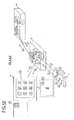
- Figure 27(b) shows an entire process of an injection molding process.
- the stamper 206 is attached to a stamper holder 204 and fixed so as to oppose a fixed mold 205.
- a resin 208 is injected from an injection hole for resin 207 in a direction of an arrow 209 into the fixed mold 205.
- a cutting punch 210 punches a central hole.
- the resin 28 is separated from the stamper 206 by an ejector 211.
- the embedding hole 202 having a doughnut-shape is formed in the substrate 7.
- the IC module 201 shown in Figure 27(a) can be accommodated without a gap.
- Figure 27(c) shows an example in which the embedding protrusion 212 of the IC module 201 is formed in the stamper holder 204 instead of the stamper 206.
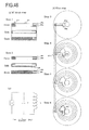
- the IC module 201 is formed on the substrate 7 on a side of the information layer 6.
- Figure 29(c) shows an example in which the substrate 7 is formed on a side away from the side to be read from, while the information layer and the IC module 201 are formed in the substrate 7 on the side to be read from.
- an IC portion of the IC module 201 can be prevented from being seen from the label side, providing an effect of improving the design.
- Figure 29(d) shows an example in which the substrate 7 is formed on the side to be read from.
- the thickness of two substrates within the range of 0.55 to 0.64 mm and the thickness of the adhesive layer 216 to 0.055 ⁇ 0.015mm, an effect that the disc can be reproduced by a player of DVD standards can be achieved.
- Figure 29(e) shows an example in which a blue laser is used.
- the thickness of the substrate 7 is set to be 1.1 mm or smaller and the thickness of the adhesive layer is set to be 0.025 mm.
- the other substrate 215 does not have an information layer 6.
- a substrate 215a, and, also, the IC module 201 are formed on the side of the optical disc 217 opposite to the side to be read from.
- the contents of the information layer are different for every title.
- the optical disc 217 is defective in both of the cases where the IC module is defective and where the information layer 6 is defective, increasing the total number of possible defects.
- defects of the substrate 215a and the defects of the substrate 7 can be separated from each other. By bonding only good substrates 215a to the substrate 7, an effect of reducing the number of defects of the completed optical disc 217 can be achieved.
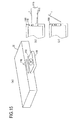
- a method for fabricating the substrate 215a will be described with reference to Figure 28 .
- a stamper holder 204a having the embedding protrusion 212 is fixed to the fixed mold 205.
- the resin 208 is injected to form the substrate 7.
- a mechanical angle identifying recessed portion 220 is provided with high precision along an A-A' cross section of a liquid pool protrusion 222 of the stamper holder 204.
- the mechanical angle identifying recessed portion 220 is a notch having a depth of d mm.
- an angle identifying mark 223 composed of a protrusion of height d is formed in a circumferential trench of the substrate 7 of the optical disc.
- an angle identifying protrusion 221 is provided at an angle of ⁇ .
- a corresponding angle identifying recessed portion is provided in an embedding protrusion 224.
- the angle identifying protrusion 221 and the angle identifying recessed portion are fitted into each other.
- the embedding hole 202 and the angular identifying mark 223 are formed on the substrate 7 in a relative position at a high angle.
- Figure 30(e) is a cross-sectional view of the stamper holder 204 and the embedding protrusion 224.
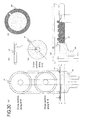
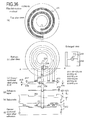
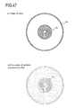
- Figure 31(a) is a top view of the IC module 201 having a double-wound antenna 231, an IC 230, an insulating layer 232, and wiring 233.
- Figure 31(b) shows a cross-sectional view along A-A' of Figure 31(a) .
- a wiring substrate 234 having a thin sheet shape of 10 to 20 ⁇ m, such as a flexible substrate is prepared. More specifically, a plurality of wirings are created together using a sheet having a large area, and then, after completion, the sheet is punched into doughnut-shapes as shown in Figure 31(a) . Thus, mass production is possible.
- a notch at a particular angular position is provided in an inner periphery or an outer peripheral portion at a particular angular position to form a similar angle identifying mark 223a.
- the antenna 231 (231a, 231b and 231c) is formed.
- the antenna 231 of a thick film can be fabricated by, for example, an electroless plating or printing method.
- the insulating layer 232 is formed.
- the wiring 233 of a bridge-type is formed over the insulating layer 232 such that the bridge crosses over the antenna 231b.
- the IC 230 is attached to two terminals of the antenna 231 by bonding.
- a bonding method can be, for example, a method using an anisotropic conductive sheet or the like. By using this method, a flat back surface of the print substrate 234 is obtained.
- wiring 233 for a bridge may be formed at the back surface of the print substrate 234 and connected by providing two through holes in the print substrate 234.
- step 2 of Figure 32 when a maximum height of the IC portion or the like of the IC module 201 is d4, the IC module 201 is attached to the substrate 7 by using an adhesive sheet 235 having a sheet thickness of d2 and a maximum depth of d4.
- the adhesive sheet is cured by heating, ultraviolet rays, or the like and fixing of the IC module 201 to the substrate 7 of the optical disc is completed.
- the IC module 201 is flat with respect to the surface of the substrate 7 of the completed disc.
- a guard band having a distance of Lg is provided between the IC module 201 and the information layer 6, a guard band having a distance of Lg is provided.
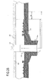
- the substrate 7 of the optical disc fabricated as shown in Figure 33(a) and the other substrates 218 are opposed to each other with a gap of 0. 025 mm to 0.05 mm therebetween and an adhesive 236 having a light transmittance is enclosed in the gap.
- the adhesive 236 flows in a direction of an arrow 237.
- the IC module 201 has the structure shown in Figure 32 , the IC module 201 is flat at the same level as the surface of the substrate 7.
- a flow of the adhesive 236 is flat on an attaching portion of the IC module 201 as indicated by arrows 237a, 237b, and 237c.
- no disturbance is generated in the flow of the adhesive 236. Therefore, a precision in intervals between the gaps is achieved and the flow of the adhesive 236 is not affected, thereby causing a significant effect that optical properties such as birefringence or the like after the adhesive 236 is cured are not deteriorated.
- the height d5 as shown in step 3 of Figure 32 which is a difference in levels of the IC module 201 and the surface of the substrate, is maintained within the range of ⁇ 0.015 mm.
- the optical disc can meet the standards for DVD or the like.
- the adhesive 236 is irradiated with ultra rays and cured to form the adhesive layer 216 ( Figure 33(b) ). In this way, an optical disc of the type in which two substrates are bonded is completed.
- a guard band having the width Lg of 1 mm or greater, an effect on an optical property of the adhesive layer of the information layer 6 by adding the IC module 201 can be eliminated.
- a method for making the substrate surface flat after embedding by previously providing an embedding hole having protruded and recessed portions on the substrate 7 side has been described above.
- a method of forming a flat embedding hole 238 in the substrate 7 will be described.
- the embedding protrusion 212 having a height of d7 is provided in the stamper 206 and injection molding is performed.
- the substrate 7 having a flat embedding hole 238 of a depth of d7 can be obtained.
- an effect of preventing deterioration in optical properties such as birefringence or the like of the transparent substrate 7 of the information layer 6 or the adhesive layer 216 can be achieved by providing a guard band, which satisfies Lg ⁇ 1 mm, between the information layer 6 and the embedding hole 238.
- the embedding protrusion 212 may be provided in the stamper holder 204. This structure provides an effect of reducing a time for fabricating the stamper 206.
- Figure 35 shows a method for mounting the IC module onto the substrate.
- the IC module 201 is mounted into the embedding hole 238 of the substrate 7, described above, via an adhesive sheet 235 from the print substrate 234 side opposite to the side on which the IC 230 is attached.
- Step 2 shows the IC module 201 being embedded into the embedding hole 238.
- a height of the IC 230 from the substrate surface is d11
- a height of the print substrate 234 from the substrate surface is d12
- the disc will meet the standards for the optical disc and thus have the compatibility.
- the IC 230 and the antenna 231 are formed on the print substrate 234 such that the volume of the IC module 201 within the range of d11 (i.e., a total sum of the volume of a portion of the IC module 201 protruding from a surface of the substrate 7 to be bonded) and the volume of a gap portion except for an antenna or IC within the range of d12 (i.e., a total sum of the volume of a gap portion which is recessed with respect to the surface on which the substrate 7 is bonded) are about the same.
- an adhesive 236 is enclosed in a step of bonding the substrate 7 and the substrate 218 shown in step 3, when the volumes are averaged, they are even out to be zero.
- the embedding portion of the IC module 201 can be regarded equivalently that it has the same height as the surface on which the substrate 7 is bonded. Since they have equivalently the same heights, the same volume of the adhesive is enclosed in the IC module region, the substrate portion, and the portion of the information layer 6. Thus, the adhesive 236 is distributed with a uniform thickness. This provides an effect that the thickness of the adhesive layer 216 becomes uniform. In such a structure, an alignment in an angular direction is not necessary. This eliminates not only the need for an angle identifying mark but also a step for aligning in an angular direction.
- Figure 36 shows an embodiment in which the IC 230 and the bridge wiring 233 are provided on a side of the embedding hole of the substrate, and the antenna 231 is provided on the side opposite to the embedding hole of the substrate 7.
- the double-wound antenna 231 is formed on a top surface (surface) of the print substrate 234.
- the bridge wiring 233, the wiring 239 and the IC 230 are formed on a back surface of the print substrate 234.
- Figure 36(c) shows a cross-section along A-A' of the IC module shown in Figure 36(b) .
- the thickness d17 of the antenna 231 is 8 ⁇ m of skin depth for 13.5 MHz as described above.
- the thickness d13 of the print substrate 234 is 15 through 20 ⁇ m
- the thickness d14 of the wiring 239 is 8 ⁇ m
- the thickness d19 of the IC 230 is 50 ⁇ m
- the thickness d16 of an adhesive layer is 15 ⁇ m
- the maximum thickness d22 is 100 ⁇ m.
- the adhesive layer 216 of the bonded portion cannot fall within the range of 55 ⁇ 15 ⁇ m.
- Figure 36(e) shows a cross-section of the substrate 7.
- the maximum depth d20 of the embedding hole 202 of the substrate 7 is about 90 ⁇ m, and the minimum depth d21 is about 30 ⁇ m.
- Figure 36(f) shows the IC module ( Figure 36(c) ) being adhered onto the substrate 7 ( Figure 36(e) ) via the adhesive layer ( Figure 36(d) ).
- the IC module is adhered onto the substrate 7 via the adhesive layer such that the antenna 231 is on the opposite side to the embedding hole of the substrate 7 and the bridge wiring 233, the wiring 239 and the IC 230 are on the side of the embedding hole of the substrate 7.
- the print substrate 234 and the IC 230 are suitably accommodated below a surface of the substrate 7 and only the antenna 231 protrudes from the surface of the substrate 7.
- the protruded height d22 of the antenna 231 is 8 ⁇ m for 13.5 MHz.
- the flow of the adhesive 236 during the bonding step is improved. This provides an effect that the optical property is not deteriorated and the thickness of the adhesive layer 216 becomes more uniform. Further, since the angle identifying mark 223a is provided in the IC module, the embedding hole of the substrate and the IC module can be mounted with a high precision in an angular direction.
- the IC module produced as described above is mounted into the embedding hole on the side on which the substrate is bonded and the substrates are bonded. Firstly, the IC module can be protected by the adhesive layer without providing a special step for forming a protection layer, and thus, the effects that the number of steps for forming a protection layer can be reduced and the reliability of an environmental resistance is improved, are obtained. Furthermore, since the IC module is at about 0.6 mm or 1.1 mm inside the disc, the effect that the IC module is prevented from being destroyed by a mechanical contact from outside the completed bonded disc, is provided. Similar effects can be obtained by a method for directly forming an antenna which will be described below.
- a method for producing an IC module and attaching the IC module to an embedding portion of the substrate has been mainly described above.
- a method for forming an antenna directly on a disc substrate will be described.
- a skin depth of an antenna will be 8 ⁇ m and 0.6 ⁇ m for 13.5 MHz or 2.5 MHz, respectively.
- an antenna can be formed by a thin-film method such as sputtering or the like.
- an electric field of the antenna is decreased exponentially as the depth of a metal film increases. The energy is the integrated value of a square of the electric field.
- the antenna 231 is formed along a circumferential direction of the substrate 7 of the optical disc.
- step 1 an embedding hole 240 which has a shape elongated in the circumferential direction is pre-formed on the substrate 7 by an injection molding.
- step 2 the antenna 231 is formed by sputtering with a notch 242 locally formed using a mask 241.
- step 3 the IC 230 is bonded to a portion of the notch 242 of the antenna 231.
- the IC 230 is fixed by bonding or the like using wire bonding or an anisotropic conductive sheet.
- step 3 of Figure 35 another substrate is provided to oppose and the adhesive 236 is enclosed therebetween to complete an optical disc.
- the IC 230 is enclosed within the adhesive 236.
- a step of forming a protection layer is not necessary.
- the protection layer 243 is provided over the IC 230 as shown in step 4 in Figure 38(b) .
- a sub-substrate 244 is formed.
- a small IC block 247 is formed by attaching the IC 230 to the sub-substrate 244.
- the adhesive sheet 235 is attached.
- the small IC block 247 is attached to an embedding hole 240 of the substrate.
- the IC 230 is protected by the sub-substrate 244.
- an antenna conductor having a thin thickness in the order of sub-micron is formed.
- the thickness of the antenna conductor does not reach the skin depth and the transmission/reception efficiency of the antenna may be deteriorated.
- the antenna conductor may be treated with electrolytic plating or electroless plating without electrodes.
- the electrolytic plating may be performed by, for example, attaching electrodes to the antenna conductor and covering other metal portions, and/or recording film portions with a protection film, and immersing the antenna conductor into an electrolytic solution and then placing it into an electrolytic plating bath.
- a thickness of the antenna conductor can be increased and the thickness of the antenna conductor will become close to the skin depth.
- the thickness of the antenna conductor can be increased. As a result, it becomes possible to improve the transmission/reception efficiency of the antenna.
- Figure 38 shows a method in which the antenna 231 is first formed and then the IC is mounted.
- Figure 39 a method in which the antenna 231 is formed after the IC 230 is mounted will be described.
- a rectangular embedding hole 240 which is elongated in the circumferential direction is formed at the time of the injection molding in step 1, similarly to the method shown in Figure 38 .
- the sub-substrate 244 of thickness d5 is formed.
- electrodes 245 and 246 which are divided into two are formed around the sub-substrate 244.
- the IC 230 is attached.
- the adhesive sheet 235 is attached.
- the sub-substrate 244 is attached into the embedding hole 240. As shown in a top view, the electrodes 245 and 246 are exposed.
- terminals 231a and 231b of the antenna 231 are formed by sputtering or the like.
- the antenna 231 and the IC 230 are electrically connected.
- the IC 230 is protected by the sub-substrate 244.
- a sputtering step can be performed in later steps.
- the electrodes 245 and 246 and the substrate surface have the same level of height and they are continuous. Therefore, even when the antenna 231 is formed using a thin-film process and connected, the possibility of later destruction is reduced, thereby providing an effect of improving reliability.
- the sub-substrate with electrodes in step 3 can be produced on a mass-production basis by only providing two electrodes in both ends of a long sheet of the substrate and cutting the sheet into strips.
- a sub-substrate can be implemented at an extremely low cost.
- a step of forming a metal film on an aluminum alloy or a silver alloy, by sputtering, is carried out in a production process of an optical disc of a RAM type or a ROM type.
- such a step of forming a metal film is utilized to form the antenna.
- the antenna and/or wiring can be formed in the inner peripheral portion of the optical disc without increasing the steps of forming a film. This provides a significant effect that the IC of RF-ID and the antenna can be formed in the optical disc without increasing the cost, except for the cost for the IC.
- the single-wound antenna does not cause any problem.
- the sensitivity is deteriorated.
- a multiple-wound type antenna wound for n times is required.
- Figure 40(a) is a top view of an optical disc provided with a multiple-wound antenna.
- An IC block 247 which has the positions of electrodes shifted from those in the rectangular IC block 247 described with reference to Figure 39(b) , is embedded into the rectangular embedding hole 240 of the substrate 7.
- Two terminals of the three-time-wound antenna 231 are formed at both ends thereof by sputtering.
- step 1 the IC block 247 is fixed into the embedding hole 240 with the adhesive sheet 235.
- the electrodes 245 and 246 are exposed on the substrate surface.
- step 2 on the exposed electrodes 245 and 246, both ends of the antenna 231 are formed by sputtering.
- the electrodes 245 and 246 and the terminals 231a and 231d at both ends of the antenna 231 are electrically connected respectively.
- Figure 40(c) shows steps 1 and 2 described above, when viewed from the top.
- Figure 40(d) is a cross-sectional view when a liquid adhesive is used for adhesion. Some rises of adhesive are observed between the substrate 7 and the electrodes 245 and 246 of the IC block 247, but bonding therebetween become more firm. Thus, in the case where the terminals of the antenna 231 are formed by sputtering as shown in step 2, the possibility of a break in wire can be reduced.
- Figure 40(e) shows an example in which four bent portions 248a, 248b, 248c, and 248d are provided in the wiring of the antenna 231 of Figure 40(a) .
- the wiring of the antenna 231 has a spiral shape with a diameter decreasing as the spiral extends from the outer periphery to the inner periphery of the optical disc.
- the bent portions of the wiring of the antenna 231 are formed in order of the bent portions 248b, 248a, 248d, and 248c from the outer periphery to the inner periphery of the optical disc.
- the diameter of the wiring (winding) of the antenna 231 changes.
- a bridge portion (the IC block 247 or a metal conductor) which bridges over the wiring of the antenna 231 between the bent portions 248b and 248a and the wiring of the antenna 231 between the bent portion 248d and 248c is provided.
- the bridge portion is connected to the end of the inner periphery of the wiring of the antenna 231 and the end of the outer periphery of the wiring of the antenna 231.
- Such a winding arrangement of the antenna provides an effect that the antenna can be accommodated within a smaller circle.
- the recording region starts at a diameter of about 23 mm.
- only a narrow region from the inner periphery to a central hole can be utilized as an antenna area.
- forming bent regions provides a significant effect for an optical disc because an antenna having a larger number of windings can be accommodated.
- a recording region is formed by film formation steps for 6 to 8 layers. These layers include a metal layer which reflects a light and has a high electric conductivity. There is also a plurality of layers for adjusting absorption of light. These layers are insulators having low electric conductivity. Further there is a semiconductor layer. The semiconductor layer is formed by a sputtering method. The semiconductor layer can also be formed by evaporation. The present invention is characterized in that an antenna, capacitor, resistance, and wiring are formed in the same step by utilizing film formation steps of the metal layer, dielectric, and semiconductor. Thus, production in a short time and at a low cost can be implemented by omitting a part or all of the steps for an antenna, wiring and the like.
- At least a part of an antenna can be formed by utilizing a film formation step for a metal reflection film included in an information layer on/from which information can be recorded/reproduced.
- a metal reflection film and an antenna are formed such that the thickness and the composition of the metal reflection film are substantially the same as the thickness and the composition of at least a part of the antenna.
- an example of the structure of an information layer of a current recording-type disc is the substrate 7, which is composed of a transparent layer of polycarbonate and has a thickness of 0.6 mm, 1.1 mm, or 0.75 mm for the case of the bonded disc, and 0.8 mm or 1.2 mm for the case of a single plate.
- an interface layer 252 composed of a dielectric having a thickness of few nm, a recording layer 253, an interface layer 254, a dielectric layer 255 having a thickness of 30 nm, a light absorption layer 256 having a thickness of 10 nm, and a reflection layer composed of Ag alloy or Al alloy having the thickness of 100 nm, are formed.
- the films are formed in the above-mentioned order.
- films are formed in the reversed order, i.e., the reflection layer 257 is formed on the substrate 7, the light absorption layer 256 is formed thereon, and so on.
- Such a case can be implemented by performing the steps of the present invention in the reversed order.
- step 1 the embedding hole 202 is provided on the substrate 7.
- step 2 the IC block 247 is attached.
- step 3 of Figure 42 sputtering by metal targets 261a using a mask 260a is used to form the antenna 231 as shown in Figure 43 .
- step 4 sputtering by a dielectric target 261a is performed to form a dielectric layer 255 in the recording region and the region of the capacitor by the mask 260b.
- Step 4 of Figure 43 shows a top view.
- step 5 the region of the antenna 231 and the capacitor 263 are covered with the mask 260c and the interface layer 254 and the recording layer 253, as shown in Figure 41 , are sequentially formed in the recording region by sputtering.
- step 6 sputtering is performed by a metal target 261 of an aluminum or silver alloy, after the mask 260d is formed, on at least a part of the antenna 231 to form the reflection layer 257 and the electrode 262.
- At least a part of the antenna 231 is formed by utilizing film formation steps of metal reflection films included in the information layer.
- the metal reflection film and the antenna are formed such that the thickness and the composition of the metal reflection film are substantially the same as the thickness and the composition of at least a part of the antenna 231.
- at least a part of the capacitor 263 is formed by utilizing the film-formation step for a dielectric film included in the information layer.
- the dielectric film and the capacitor 263 are formed such that the thickness, and the composition of the dielectric film, are substantially the same as the thickness and composition of at least part of the capacitor 263.
- the capacitor 263 is formed for producing a resonance circuit as shown in Figure 44(a) , (b), and (c) when an inductance of the antenna is L.
- Figure 45(a) is a top view of the mask 260b used for step 3 shown in Figure 42 .
- the antenna 231 is formed by sputtering using the mask 260b.
- formation of a reflection film of an Ag alloy having a thickness of 0.05 ⁇ m takes 1 second.
- it takes nearly 10 seconds to form a skin depth of 0.6 ⁇ m for 2.5 GHz even if it is cooled.
- four discs are put in a chamber of sputtering at the same time as shown in Figure 45(b) .
- the cycle time becomes one fourth the original length, 2-3 seconds for each disc.
- the step can be introduced in a mass-production line in view of the cycle time.
- Implementing the skin depth of 8 ⁇ m for 13.5 MHz is difficult to be intruded into a mass-production line in view of the cycle time.
- the mass-production step can be implemented by improving the substantial sensitivity by making the film thickness about 1-2 ⁇ m, lowering the antenna sensitivity, and introducing a resonance circuit in the capacitor of the present invention.
- a first difference is the structure of the IC block 247.
- one electrode 246 is separated into an electrode 246a and an electrode 246b.
- the IC 230 is connected to the electrode 246a.
- the IC block 247 is mounted.
- the antenna 231 is formed such that one terminal 231b of the antenna is electrically coupled to the electrode 246b.
- the dielectric layer 251 is formed.
- step 6 the reflection layer 257 is formed by sputtering such that the electrode 262 is electrically coupled to the terminal 231b of the antenna 231.
- a step of fabricating the antenna and IC portion having a resonance circuit as shown in Figure 46(c) can be performed while also serving as a film formation step of the recording film.
- sputtering is performed by a target 260 of Al or Ag.
- a single-wound antenna 231 and the reflection film 257 as shown in Figure 48(b) are formed.
- a disc with an antenna and IC can be formed. This is achieved by only adding one step of IC bonding, there is an effect that the disc can be fabricated extremely easily at a low cost.
- This method can be applied to both a RAM disc and a ROM disc. Further, two discs are bonded with the IC 230 inside to form one disc. The antenna and IC are protected from the external environment. Thus, a high reliability can be achieved.
- the simplest method is to use an IC with an antenna for RF-ID, embed the IC in the embedding hole 240 of the substrate 7, and bond the disc with the IC inside. If the cost of such an IC is reduced, a disc with a high reliability can be readily fabricated with this method.
- Figure 49(a) is a diagram showing a back surface of a thin film antenna 231g. Through holes 271a and 271b are provided in an antenna 231h on the inner peripheral portion.
- Figure 49(b) is a top view showing the antenna 231d formed.
- a fabrication step of a through hole will be described. In step 1, sputtering is performed using the metal target 261 from a surface to the through hole 271 of the substrate 7 to form a metal layer 272a on the upper half part of the through hole 271. In step 2, a metal layer 272b is formed on the lower half part of the through hole 271 from the back surface side.
- the metal layer 272a on the surface side and the metal layer 272b on the back surface side are electrically coupled.
- the IC 230 is bonded on the back surface to complete the antenna and the IC portion.
- this disc is bonded with another disc to complete one disc.
- the adhesive 236 for bonding flows into the through hole and fills the hole.
- a protection layer 272 is formed for protecting the antenna 231c on a top surface.
- the antenna has two poles of surface and the back surface. Thus, it also serves as a dipole antenna.
- Figure 50(a) is a top view of the remote control 15.
- Figure 50(b) is a side view thereof.
- the remote control 15 incorporates an antenna 282, an activation switch 280, and a speaker 281.
- the activation switch 280 is not pressed and thus it is not activated.
- Figure 50(d) when the remote control is inclined and pressed against the optical disc 1, as shown in Figures 51 and 52 , the activation switch is turned on and the RF signal is transmitted and received by the antenna 231 of the optical disc 1, and the IC 230 transmits a response signal including an ID from the antenna 231.
- the signal is received by the antenna 282 and a confirmation sound is produced from the speaker 281 to notify the operator. After a certain amount of time has elapsed, power supply to the transmission circuit is stopped.
- the remote control 15 Since the remote control 15 is mounted with a battery of a small capacity, it is necessary to limit an operation of the circuit for transmitting an RF signal as small as possible.
- the method shown in Figure 50 provides an effect of reducing power supply consumption and extending the lifetime of the battery of the remote control since the power supply is turned on, the RF signal is transmitted, and the ID is detected for a certain amount of time when the switch 280 is pressed against the disc 1.
Abstract
Description
- The present invention relates to an optical disc and a remote control device.
- In recent years, ID information is becoming more important. Experimentation on incorporating integrated circuits including ID information has been attempted. Such kinds of applications are expected to continue in the future (see, for example, Japanese Laid-Open Publication No.
2002-83482 - Portable-type optical discs are dispersed after recording of the contents due to their portability. Thus, there is a demand for a method of searching for contents which have been recorded in the portable optical discs. The objective of the present invention is to provide an optical disc and a remote control device which enable searching for contents recorded on an optical disc by mounting an IC including ID information on an optical disc.
- According to the present invention, a transmitting antenna and a receiving antenna are provided in an inner peripheral portion of an optical disc, and a transmission/reception IC which stores ID information of the optical disc is connected to the antennas.
- With such an optical disc, a system which can search for ID information of an optical disc from a recording/reproduction apparatus over radio waves can be provided.
-
-
Figure 1 is a top view of an optical disc according to one embodiment of the present invention. -
Figure 2(a) is a top view of an optical disc according to one embodiment of the present invention, andFigure 2(b) is a top view of a tip portion of an optical disc according to one embodiment of the present invention. -
Figure 3(a) is an electrolytic profile showing a directivityofanantennaA, andFigure 3(b) is an electrolytic profile showing a directivity of an antenna B, andFigure 3(c) is an electrolytic profile showing a directionality of the antenna A plus the antenna B. -
Figure 4 (a) is a top view of an optical disc according to one embodiment of the present invention, andFigure 4(b) is a top view of a tip portion of an optical disc according to one embodiment of the present invention. -
Figure 5 is a diagram showing an appearance of an optical disc according to one embodiment of the present invention. -
Figure 6 is a block diagram showing structures of an optical disc, a remote control, and a recording/reproduction apparatus according to one embodiment of the present invention. -
Figure 7 is a timing diagram showing a reception signal and a detection signal according to one embodiment of the present invention. -
Figure 8 is a waveform profile of a reception signal and a detection signal according to one embodiment of the present invention. -
Figure 9 is a diagram showing a data structure of a disc information file according to one embodiment of the present invention. -
Figure 10 is a diagram showing a data structure of a disc information file according to one embodiment of the present invention. -
Figure 11 is a flow chart showing a procedure according to one embodiment of the present invention. -
Figure 12 is a flow chart showing a procedure according to one embodiment of the present invention. -
Figure 13 is a diagram showing an operation of an optical disc and a remote control according to one embodiment of the present invention. -
Figure 14 is a diagram showing an operation flow of an optical disc and a remote control according to one embodiment of the present invention. -
Figures 15(a) -(c) show an operation of a tray of a recording/reproduction apparatus according to one embodiment of the present invention. -
Figure 16 is a top view of an optical disc according to one embodiment of the present invention. -
Figures 17(a) -(d) are diagrams showing an attachment operation of a disc according to one embodiment of the present invention. -
Figure 18 is a flow chart showing a process procedure according to one embodiment of the present invention. -
Figure 19 is a flow chart showing a process procedure according to one embodiment of the present invention. -
Figure 20 is a flow chart showing a process procedure according to one embodiment of the present invention. -
Figure 21 is a block diagram showing a structure of a recording/reproduction apparatus according to one embodiment of the present invention. -
Figure 22 is a flow chart showing a procedure according to one embodiment of the present invention. -
Figure 23 is a flow chart showing a procedure according to one embodiment of the present invention. -
Figures 24(a) -(c) are diagrams showing a method for detecting ID information according to one embodiment of the present invention. -
Figure 25 is a top view of an optical disc according to one embodiment of the present invention. -
Figure 26 is a flow chart showing a procedure according to one embodiment of the present invention. -
Figures 27(a) -(c) are cross-sectional views illustrating a step of forming a substrate with an embedding hole according to one embodiment of the present invention. -
Figure 28 is a cross-sectional view illustrating a step of forming a substrate with an embedding hole according to one embodiment of the present invention. -
Figures 29(a) -(e) are diagrams showing a positional relationship between an IC module and an information layer in a substrate according to one embodiment of the present invention. -
Figures 30(a) -(e) are diagrams showing a step of forming an angle identification mark according to one embodiment of the present invention. -
Figure 31(a) is a top view of an antenna portion of an optical disc according to one embodiment of the present invention, andFigure 31(b) is a cross-sectional view of an antenna portion of an optical disc according to one embodiment of the present invention. -
Figure 32 is a cross-sectional view illustrating an IC module of an antenna portion of an optical disc according to one embodiment of the present invention. -
Figures 33(a) and (b) are cross-sectional views illustrating a step of bonding an antenna portion of an optical disc according to one embodiment of the present invention. -
Figures 34(a) and (b) are cross-sectional views illustrating a step forming an inner peripheral portion of an optical disc according to one embodiment of the present invention. -
Figure 35 is a diagram illustrating a step of producing an IC module according to one embodiment of the present invention. -
Figures 36(a) -(f) are diagrams illustrating a step of producing an IC module according to one embodiment of the present invention. -
Figure 37 is a diagram showing an efficiency of an antenna according to one embodiment of the present invention. -
Figure 38(a) is a diagram showing a directly-formed antenna;Figure 38(b) is a diagram illustrating a step of directly bonding an IC according to one embodiment of the present invention; andFigure 38(c) is a diagram illustrating a step of mounting an IC using a sub-substrate according to one embodiment of the present invention. -
Figures 39(a) -(d) are diagrams illustrating a step of mounting a single-wound antenna and an IC. -
Figures 40(a) -(e) are diagrams illustrating a step of mounting a multiple-wound antenna and an IC. -
Figure 41 is a diagram showing a structure of an information layer according to one embodiment of the present invention. -
Figure 42 is a diagram illustrating a step of forming antenna wiring, capacitor during a film formation step for an information layer according to one embodiment of the present invention. -
Figures 43(a)-(c) are diagrams illustrating a step of forming an IC, an antenna, and a capacitor according to one embodiment of the present invention. -
Figures 44(a) -(c) are diagrams showing a resonance circuit according to some embodiments of the present invention. -
Figure 45(a) is a diagram showing a shape of a mask according to one embodiment of the present invention, andFigure 45(b) is a diagram showing a step of forming four films at the same time according to one embodiment of the present invention. -
Figure 46(a) is a diagram showing a step of producing an IC block according to one embodiment of the present invention;Figure 46(b) is a diagram showing a step of producing a disc according to one embodiment of the present invention; andFigure 46(c) is a diagram showing an equivalent resonance circuit according to one embodiment of the present invention. -
Figure 47(a) is a diagram showing a shape of a mask according to one embodiment of the present invention, andFigure 47(b) is a top view of an antenna and a reflective film which have been formed according to one embodiment of the present invention. -
Figure 48(a) is a diagram showing a shape of a mask according to one embodiment of the present invention, andFigure 48(b) is a top view of an antenna and a reflective film which have been formed according to one embodiment of the present invention. -
Figure 49(a) is a view of a back surface of an antenna according to one embodiment of the present invention;Figure 49(b) is a top view of an antenna according to one embodiment of the present invention;Figure 49(c) is a view of a back surface of an antenna according to one embodiment of the present invention;Figure 49(d) is a cross-sectional view of an antenna according to one embodiment of the present invention; andFigure 49(e) is an enlarged cross-sectional view according to one embodiment of the present invention. -
Figure 50(a) is a top view of a remote control according to one embodiment of the present invention;Figure 50(b) is a side view of a remote control according to one embodiment of the present invention; andFigure 50(c) is a view of a back surface of a remote control according to one embodiment of the present invention. -
Figure 51 is a diagram showing a communication flow of a remote control and a reproducing apparatus according to one embodiment of the present invention. -
Figure 52 is a diagram showing a communication flow of a remote control and a recording/reproduction apparatus according to one embodiment of the present invention. - Hereinafter, an embodiment of the present invention will be described with reference to the drawings.
- Hereinafter, an embodiment of the present invention when applied to a recording medium having a disc shape will be described.
-
Figure 1 is a diagram showing an example of a structure of anoptical disc 1 according to an embodiment of the present invention. - In an inner peripheral portion of the
optical disc 1, a transmittingantenna 2 and a receivingantenna 3 are provided. The transmittingantenna 2 and the receivingantenna 3 are formed along a circumferential direction of theoptical disc 1. In this example, the transmittingantenna 2 and the receivingantenna 3 are both dipole antennas. - In the inner peripheral portion of the
optical disc 1, a transmission/reception IC 4 connected to the transmittingantenna 2 and the receivingantenna 3 is further provided. The transmission/reception IC 4 receives radio waves via the receivingantenna 3 and transmits radio waves via the transmittingantenna 2. In this example, the transmission/reception IC 4 is formed on a chip. The chip is called an RFID chip. - In a central portion of the
optical disc 1, ahole 5 which allows theoptical disc 1 to be attached to a rotation member for rotating theoptical disc 1 is provided. - In an outer peripheral portion of the
optical disc 1, aninformation layer 6 , on which information can be recorded or from which information can be reproduced, is provided. Theinformation layer 6 is formed between asubstrate 7 and atransparent layer 8. Anadhesive layer 9 is formed between thesubstrate 7 and theinformation layer 6. -
Figure 2(a) is an enlarged view of a portion around the transmittingantenna 2 and the receivingantenna 3 shown inFigure 1 . - The transmitting
antenna 2 includes transmittingantenna portions antenna 3 includes receivingantenna portions antenna portions antenna portions -
Figure 2(b) is a portion around the transmission/reception IC 4 shown inFigure 1 . - The receiving
antenna portions reception IC 4 via arelay substrate 11. The transmittingantenna portions reception IC 4 viawiring relay substrate 11. Thewiring 10a extends the transmittingantenna portion 2a. Thewiring 10b extends the transmittingantenna portion 2b. Thewiring - As indicated by a cross-section along B-B' in
Figure 2(a) , a portion of thesubstrate 7 in which therelay substrate 11 is located is dug down by thickness d. The thickness d is designed such that the transmission/reception IC 4 will not be in contact with a recording/reproduction apparatus when theoptical disc 1 is attached to the recording/reproduction apparatus. Herein, the recording/reproduction apparatus is an apparatus which performs at least one of a recording operation for recording information on theoptical disc 1 and a reproduction operation for reproducing information recorded on theoptical disc 1. - When the length of the transmitting
antenna portions antenna portions antenna 2 and the receivingantenna 3 in an inner peripheral portion of a standard optical disc having a diameter of 120 mm. - With reference to
Figure 3 , a directivity of dipole antennas will be described. -
Figure 3(a) shows a directivity of a dipole antenna A. It is shown that the antenna A is not sensitive in a longitudinal direction of dipoles of the antenna A (i.e., y direction). -
Figure 3(b) shows a directivity of a dipole antenna B shifted by 90° with respect to the dipole antenna A. It is shown that the antenna B is not sensitive in a longitudinal direction of dipoles of the antenna B (i.e., x direction). -
Figure 3(c) shows a directivity of an antenna in the case in which the dipole antenna A and the dipole antenna B are arranged in combination. The dipole antenna B is arranged so as to be shifted by 90° with respect to the dipole antenna A. It is shown that an antenna which is sensitive in all directions can be implemented by arranging the antennas A and B such that a dead zone of the antenna A and a dead zone of the antenna B are orthogonal to each other. - The transmitting antenna 2 (
Figure 1 ) and the receiving antenna 3 (Figure 1 ) are arranged so that the dead zone of the transmittingantenna 2 and the dead zone of the receivingantenna 3 are orthogonal to each other. Thus, as shown inFigure 3(c) an antenna which is sensitive in all directions can be implemented. As a result, regardless of an orientation of theoptical disc 1, ID information (RFID) stored in the transmission/reception IC 4 of theoptical disc 1 can be detected. -
Figure 4(a) shows another example of the structure of theoptical disc 1 according to an embodiment of the present invention. In this example, a loop-type antenna is used instead of a dipole antenna. - In an inner peripheral portion of the
optical disc 1, a transmittingantenna 2 and a receivingantenna 3 are provided. The transmittingantenna 2 and the receivingantenna 3 are formed along a circumferential direction of theoptical disc 1. In this example, the transmittingantenna 2 and the receivingantenna 3 are both loop antennas. The receivingantenna 3 is positioned such than it is closer to the outer periphery compared to the receivingantenna 2. - In the inner peripheral portion of the
optical disc 1, a transmission/reception IC 4 connected to the transmittingantenna 2 and the receivingantenna 3 is further provided (seeFigure 4(b) ). The transmission/reception IC 4 receives radio waves via the receivingantenna 3 and transmits radio waves via the transmittingantenna 2. -
Figure 4(b) is an enlarged view of portion A shown inFigure 4(a) .Terminals antenna 2 andterminals antenna 3 are connected to the transmission/reception IC 4 via arelay substrate 11. - When the length of the circumference of the loop antenna is L and the wavelength is λ, the antennas are set to be L=λ. Since λ=300/f, λ=125 mm. For a frequency f GHz, based on an empirical rule, a film thickness of an antenna is 2/√f µm. Accordingly, when f=2.45 GHz, a film thickness of an antenna may be 1.5 µm or more.
- As described above, an antenna formed along a circumferential direction of an
optical disc 1 and anoptical disc 1 including a transmission/reception IC 4 for transmitting/receiving radio waves via the antennas are within the scope of the present invention. An antenna which is formed on theoptical disc 1 is not limited to the above-mentioned two-types of antennas (i.e., dipole antenna and loop antenna). -
Figure 5 shows an appearance of theoptical disc 1, aremote control 15, a recording/reproduction apparatus 35 and adisplay portion 100.Figure 6 shows an example of the structure of theoptical disc 1,remote control 15 and recording/reproduction apparatus 35. - When aviewbutton 16 of the remote control is pressed, radio waves having a particular frequency (for example, 2.45 GHz) radiate from a transmitting
section 17 and a transmittingantenna 18 to theoptical disc 1, as indicated by anarrow 19a. Such radio waves are received by the receivingantenna 3 of theoptical disc 1 and detected by adetection section 21 of a receivingcircuit 20. Thus,power 22 and a signal are obtained. Thepower 22 is sent to a signal generation section 23 and temporarily accumulated in a power accumulation section 24 such as a capacitor or the like. This feeble power is used to read outID 25 in an IDnumber storage section 26. An IDnumber generation section 27 and a modulation section 28 generate a modulation signal including the ID number. The modulation signal is delayed by a time period corresponding to atime constant 30 by atime adjusting section 29. Thetime constant 30 is preset when the transmission/reception ICs 4 is fabricated such that every transmission/reception ICs 4 has adifferent time constant 30. - The
ID 25 is information for identifying theoptical disc 1. TheID 25 is also called ID information. TheID 25 is not limited to a number (it may be a combination of alphanumeric characters, symbols and the like). The signal generation section 23 generates a signal including ID information in response to a signal output from the receiving circuit (receiving section) 20. -
Figure 7 shows an example of waveforms of a reception signal received from theremote control 15, response signals from a plurality of optical discs 1 (#1-#4) responding to the reception signal, and a detection signal detected by theremote control 15. - The
optical discs # 1, #2, #3, and #4 have different response times t1, t2, t3 and t4 to the reception signal from theremote control 15. This is because thetime constants 30 in the transmission/reception ICs 4 mounted on theoptical discs # 1 through #4 are different from each other. Thus, waveforms of the response signals from theoptical discs # 1 through #4 are different as shown inFigure 7 . - The waveform of the detection signal detected by the
remote control 15 is as shown inFigure 7 . The response signals from theoptical discs # 1 through #4 are separated in a time-wise manner from each other. Thus, even when a plurality ofoptical discs 1 are present within the scope that the radio waves from theremote control 15 can reach, theremote control 15 can separate signals transmitted from a plurality ofoptical discs 1 in a time-wise manner and detect them. In this way, collision of the response signals from a plurality ofoptical discs 1 can be prevented. - In the
remote control 15, the response signals from a plurality ofoptical discs 1 are separated in a time-wise manner by time separation means 32 (Figure 6 ). Thus, IDs of theoptical discs 1 can be identified stably. - Instead of presetting the
time constants 30 such that every transmission/reception IC 4 has adifferent time constants 30, a randomnumber generation section 34 for generating time constants at random may be provided to achieve similar effects. -
Figure 8 shows another example of waveforms of a reception signal received from theremote control 15, response signals from a plurality of the optical discs 1 (#1-#4) responding to the reception signal, and a detection signal detected by theremote control 15. - The
optical discs # 1, #2, #3, and #4 have response signals having different amounts of shifts f1, f2, f3 and f4 in central frequencies from that of the reception signal from the remote control 15 (for example, an excitation signal having a particular central frequency). This is because the frequencies set by frequency setting sections 31 in the transmission/reception ICs 4 mounted on theoptical discs # 1 through #4 are different from each other. Thus, waveforms of the response signals from theoptical discs # 1 through #4 are different as shown inFigure 8 . - The waveform of the detection signal detected by the
remote control 15 is as shown inFigure 8 . The response signals from theoptical discs # 1 through #4 are separated from each other with respect to the frequencies. Thus, even when a plurality ofoptical discs 1 are present within the scope that the radio waves from theremote control 15 can reach, theremote control 15 can separate signals transmitted from a plurality ofoptical discs 1 with respect to the frequencies and detect them. In this way, collision of the response signals from a plurality ofoptical discs 1 can be prevented. - In the
remote control 15, the response signals from a plurality ofoptical discs 1 are separated with respect to the frequencies by frequency separation means 33 (Figure 6 ). Thus, IDs of theoptical discs 1 can be identified stably even within one time zone. - In the examples shown in
Figures 7 and8 , the number ofoptical discs 1 which respond to the reception signal is not limited to four. N number ofoptical discs 1 may respond to the reception signal. Herein, n is any integer of 1 or greater. - Further, in an example shown in
Figure 6 , thetime adjusting section 29 and the frequency setting section 31 are both included in the signal generation section 23. This example is preferable because the response signals from a plurality ofoptical discs 1 can be separated in a time-wise manner and also with respect to the frequencies. However, the signal generation section 23 may include only one of thetime adjusting section 29 and the frequency setting section 31. In this case, it is sufficient if only one of the time separation means 32 and the frequency separation means 33 is included in the receiving section of theremote control 15. - Next, with reference to
Figure 6 , exchange of data between theremote control 15 and the recording/reproduction apparatus 35 will be described. -
ID reproduction section 36 receives a reception signal including ID and generatesID information 37. TheID information 37 is output to aprocessing section 38. Theprocessing section 38 displays theID information 37 on adisplay portion 39 of theremote control 15 and transmits theID information 37 to a receivingsection 44 of acommunication section 41 of the recording/reproduction apparatus 35 from a transmittingsection 42 of acommunication section 40. A method of communication between thecommunication section 40 and thecommunication section 41 may be an optical communication or may be a radio communication. - In the case where the communication between the
communication section 40 and thecommunication section 41 is an optical communication, a light emitting portion for transmitting a remote control signal which is normally equipped to theremote control 15 may also serve as the transmittingsection 42 and a light receiving portion for receiving the remote control signal which is usually equipped to the recording/reproduction apparatus 35 may also serve as the receivingsection 44. In this case, it is not necessary to additionally provide a transmittingsection 42 and a receivingsection 44. Thus, a set of a transmitting/receiving unit (light receiving/emitting unit) can be omitted. - In the case where the communication between the
communication section 40 and thecommunication section 41 is a radio communication, bidirectional communication can be performed between thecommunication section 40 and thecommunication section 41 by providing a transmittingantenna 46 and a receiving antenna 47 in thecommunication section 40, providing a transmittingantenna 49 and a receivingantenna 48 in thecommunication section 41, and using Bluetooth using radio waves of frequency 2.4 GHz or local area wireless network such as IEEE 802.11b. In this case, a transmittingantenna 46 of theremote control 15 may also serve as the transmittingantenna 18 and a receiving antenna 47 may also serve as the receivingantenna 50. Thus, a set of transmitting/receiving antennas can be omitted. - The receiving
section 44 of thecommunication section 41 outputs the receivedID information 37 to the processing section 51. In the processing section 51, asearch section 52 searches adisc information file 53 and obtains discphysical property information 54,disc logic information 55 or the like corresponding to theID information 37. -
Figure 9 shows an example of the data structure of thedisc information file 53. - In the
disc information file 53, adisc management number 57 is assigned to theID information 37.ID information 37 is data equal to or greater than 100 bits (for example, data of 128 bits). By using disc management number 57 (for example, "04"), i.e., a virtual ID having a data amount smaller than that of theID information 37, it becomes possible to manage IDs with smaller amount of data. - The
disc information file 53 includes the discphysical property information 54 and thedisc logic information 55 for each ID. - The disc
physical property information 54 includes data indicating atotal storage capacity 58 of the disc, a remainingcapacity 59 of the disc, disc type 60 (such as rewritable type, write-once type, or ROM), the number oflayers 61 of the disc (single layer or double layer) and the like. - The
disc logic information 55 includes information regarding a program recorded on the disc (program information 70). Theprogram information 70 includes property data of the program, information regarding contents, thumbnails of the contents and the like. -
Figure 10 shows program information 70a and 70b as examples of theprogram information 70 in thedisc logic information 55. - The program information 70a indicates program information of
program 1. The program information 70a includes aprogram ID 71, property data 72, andcontents data 86. - The property data 72 includes a
start address 73, anend address 74,total recording time 75, an ID of the program coming after the current program (program ID of link destination) 76, time to start and finish recording (recording time) 77, a recording source or aTV channel number 78, aprogram title 79, property information of the contents of the program 80 (a category of the program 81, a name of the characters appearing in the program 82, an area 83, program contents 84 and the like). Furthermore, in the case of a program linked to a web site, the property data 72 further includes an address of a web site of a link destination (URL) 85. - The
contents data 86 includes a still picture 87 (for example, a still picture in JPEG format or the like of the first scene of program 1) andmotion picture data 88 for first few seconds (a low-resolution motion picture 89 inMPEG 4 format or the like and a representative screen (thumbnail) of a high-resolution motion picture 90 at a high rate inMPEG 2 format or the like. Thecontents data 86 may includethumbnail data 91 which is a collection of the thumbnails. - With reference to flow charts of
Figures 11 and12 , a method for obtaining ID and displaying property information and thumbnails of the contents of the corresponding disc by using the ID will be described. - In
step 95a, the recording/reproduction apparatus 35 waits to obtain the ID information that is to be sent from theremote control 15. Instep 95b, the recording/reproduction apparatus 35 obtains new ID information which is different from the current ID information it has. Then, instep 95c, the processing section 51 defines the new ID information as the n-th ID information (i.e., ID(n)). Instep 95d, the processing section 51 searches the disc information file 53 (Figures 9 and10 ) using thesearch section 52. Instep 95e, the processing section 51 determines whether there is data regarding ID(n) in thedisc information file 53. If it is determined "Yes" instep 95e (i.e., if there is data regarding ID(n) in the disc information file 53), instep 95f , the processing section 51 determines whether theremote control 15 has the capability to display the image, or there is an image display request from theremote control 15. If it is determined "Yes" instep 95f, m=0 instep 95g and m is incremented by 1 instep 95h. Instep 95j, the processing section 51 reads out image data (motion picture data data 87, or thumbnail data 91 (Figure 10 )) of m-th program information 72 (program m) corresponding ID(n) from thedisc information file 53 by using thesearch section 52. Instep 95k, the processing section 51 transmits image data to theremote control 15 via the communication channel (a transmittingsection 45 and the transmitting antenna 49). Instep 95m, the receivingsection 43 of theremote control 15 receives the image data. Instep 95n, theprocessing section 38 extends the received image data using animage decoder 100 and displays the extended image data in the display portion 39 (Figure 13(d)) . In this way, motion picture or still picture of thumbnails of data of contents recorded in theoptical disc 1 can be confirmed by only bringing theremote control 15 close to theoptical disc 1, without attaching theoptical disc 1 to the recording/reproduction apparatus 35. Instep 95p, theprocessing section 38 determines whether the display of the image data is completed or not and continues displaying the image data until the display of the image data is completed. Even after the display of the image data is completed, instep 95q, theprocessing section 38 continues displaying the image data until a next new image display request arrives, or until a certain amount of time has elapsed. The next new image display request may be issued by, for example, a user pressing anext screen button 101 of the remote control 15 (Figure 5 ). If there is a next new image display request, it is determined "Yes" instep 95q, and the process proceeds to step 95y. Instep 95y, it is determined whether m is the last or not. If m is not the last, the process proceeds to step 95h. Instep 95h, m is incremented by 1. Instep 95j, theprocessing section 38 displays the next new image on thedisplay portion 39. - For example, in the case where the motion picture of a thumbnail of the program is displayed on the
display portion 39 of theremote control 15, motion picture data is sent from the recording/reproduction apparatus 35 (server) to theremote control 15. The processing section 51 reads out motion picture data showing a thumbnail of program 1 (for example, motion picture data for the first 5 seconds of program 1) from thedisc information file 53 and sends it to theremote control 15. The motion picture data is, for example, low-resolutionmotion picture data 89 ofMPEG 4 grade. Theprocessing section 38 receives the motion picture data and displays it on the displaying portion 39 (Figure 13(d) ). When the user presses thenext screen button 101 of theremote control 15, the processing section 51 reads out motion picture data showing a thumbnail of program 2 (for example, motion picture data for the first 5 seconds of program 2) from thedisc information file 53 and sends it to theremote control 15. Theprocessing section 38 receives motion picture data and displays it on the displaying portion 39 (Figure 13(d) ). - In
step 95q, in the case where the next image display request is issued, or a previous screen display request is issued by the user pressing aprevious screen button 102 of theremote control 15, if m is the last instep 95y, the process returns to thefirst step 95a and the recording/reproduction apparatus 35 waits to obtain the next ID information. Thereafter, the same operation as described above is performed. - In this embodiment, normal quality images and low
resolution motion picture 89 are both recorded in thedisc information file 53. However, only normal quality images may be recorded in thedisc information file 53. In this case, when a normal quality image is output, by performing rate conversion for a normal quality image (for example, MPEG2 image of 6 Mbps), the low-resolution motion picture 89 (for example,MPEG 4 image of 384 kbps) may be obtained and the low-resolution motion picture 89 may be sent to theremote control 15. - If it is determined "No" in
step 95f (i.e., when an image is not displayed on the remote control 15)), the process proceeds tosteps 96a through 96c shown inFigure 12 . If it is determined "No" instep 96c, the process proceeds to step 96d. Instep 96d, the processing section 51 reads out the property data 72 of m-th program information 72 (program m) corresponding to ID (n) using thesearch section 52, and, instep 96e, transmits it through a communication path and finally to theremote control 15. Instep 96f, the receivingsection 43 of theremote control 15 receives the property data. Instep 96g, theprocessing section 38 displays the property data (for example, remaining capacity) or the program list on thedisplay portion 39. When the program list is displayed on thedisplay portion 39, if the user presses adown key 104 of the remote control 15 (Figure 14 ), the program in a downward direction in the screen is selected. - For displaying the program list on the
display portion 39 of theremote control 15, as shown inFigure 14 , the user may (1) bring theremote control 15 close to theoptical disc 1 and (2) press aview button 16 of theremote control 15. In response, the remote control 15 (3) reads out the ID of theoptical disc 1 and (4) transmits the ID read by theremote control 15 to the recording/reproduction apparatus 35. The recording/reproduction apparatus 35 (5) searches the database to obtain the program list data and (6) sends the program list data to theremote control 15. Thus, the program list is displayed on thedisplay portion 39 of theremote control 15. When the user presses thedown key 104 of theremote control 15, (7) the program in a downward direction is selected. - With reference to the flow chart of
Figure 12 , a procedure for displaying the program list will be explained. - In
step 96h, theprocessing section 38 determines whether or not displaying the property data or the program list is completed and continues displaying the property data or the program list until displaying the property data or the program list is completed (Figure 14 ). In step 96i, theprocessing section 38 determines whether the program list is displayed on thedisplay portion 39. If it is determined "Yes" in step 96i, instep 96k, theprocessing section 38 determines whether any of thescroll buttons 101 through 104 (Figure 14 ) is pressed or not. If it is determined "Yes" instep 96k, instep 96m, theprocessing section 38 changes a program mark in the program list. Next, if a selection button 105 or an image button 106 (Figure 14 ) is pressed, instep 96p, theprocessing section 38 determines whether it is possible to display the image. If it is determined "Yes" instep 96p, instep 96q, theprocessing section 38 displays a thumbnail image, motion picture, or still picture of the selected program on thedisplay portion 39. Instep 96r, theprocessing section 38 determines whether or not the program list is completed. If it is determined "Yes" instep 96r, the process proceeds to step 96j. If it is determined "No" instep 96p (i.e., if the image cannot be displayed), the process proceeds to step 96s. Instep 96s, theprocessing section 38 displays the detailed property data of the marked program on thedisplay portion 39. The property data is read from thedisc information file 53, sent to theremote control 15, and displayed on thedisplay portion 39 of theremote control 15. As shown inFigure 10 , the property data includes, for example, category 81, name 82, area 83 and contents 84 of the program,billing identifier 85a which indicates whether or not viewing the program requires payment, andlink destination address 85 which indicates an address or URL of a website for decoding and billing. Instep 96f, theprocessing section 38 determines whether the program list is completed. If it is determined "Yes" instep 96f, the process proceeds to step 96j. Instep 96j, theprocessing section 38 determines whether there is a request for displaying the next property data. If it is determined "Yes" instep 96j, the process returns to step 96b, and the operation of incrementing m by 1, reading out the m-th property data from thedisc information file 53, and displaying the read out property data on thedisplay portion 39 is repeated. - In
step 95r, the processing section 51 determines whether or not it is possible to connect to other machines or servers. If it is determined "No" instep 95r, the process proceeds to step 95u. Instep 95u, the processing section 51 sends a message of "No data" or information indicating the message to theremote control 15 via the communication channel and displays the message or the information indicating the message on thedisplay portion 39. If it is determined "Yes" instep 95r, instep 95s, the processing section 51 connects to anothersubmachine 35a via thecommunication section 41, acommunication channel 283 and acommunication section 41a. Thecommunication channel 283 may be wired or wireless, or may be theinternet 284 as shown inFigure 6 . Instep 95s, aprocessing section 51a of thesubmachine 35a searches adisc information file 53. Instep 95t, theprocessing section 51a determines whether the disc information file includes the data corresponding to ID (n). If it is determined "Yes" instep 95t, the process proceeds to step 95v. Instep 95v, the processing section 51 determines whether theremote control 15 has a capability to display the image, or there is an image display request from theremote control 15. If it is determined "Yes" instep 95v, in step 95w, the processing section 51 reads out the image data corresponding to ID (n) from thedisc information file 53. Instep 95x, the processing section 51 sends the read out image data to the master machine (i.e., the recording/reproduction apparatus 35 inFigure 6 ) via thecommunication section 41a, thecommunication channel 283 and thecommunication section 41. Then, the process returns to step 95k. - If it is determined "No" in
step 95v (i.e., if theremote control 15 cannot display the image), the process proceeds to step 96j ofFigure 12 , the processing section 51 reads out m-th property data corresponding to ID(n) from thedisc information file 53. Instep 95k, the processing section 51 sends the read out property data to the master machine (i.e., the recording/reproduction apparatus 35 inFigure 6 ) via thecommunication section 41a, thecommunication channel 283 and thecommunication section 41. Then, the process proceeds to step 96e. Instep 96e, the property data is finally sent to theremote control 15 from the master machine. Finally, the property data is displayed on thedisplay portion 39 of theremote control 15. - Next, with reference to the flowchart of
Figure 18 , a procedure for creating a disc information file in the recording/reproduction apparatus 35 will be described. - As shown in
Figure 15(a) and (b) , amain unit antenna 110 is provided near atray 113 in which theoptical disc 1 is set. Atray antenna 112 is provided inside thetray 113. - The
main unit antenna 110 transmits radio waves periodically or when thetray 113 is slid out (step 111a). Thus, when theoptical disc 1 on which an ID chip is mounted is brought near the tray 113 (step 111b), ID information of theoptical disc 1 is read out by radio waves transmitted from themain unit antenna 110. It is determined whether reading out the ID information of theoptical disc 1 is completed (step 111c). - When the
optical disc 1 is set in thetray 113, the set signal is turned ON (step 111d). When the set signal is turned ON, thetray antenna 112 transmits radio waves (step 111e). By the radio waves transmitted from thetray antenna 112, the ID information of theoptical disc 1 is read out. It is determined whether reading out the ID information of theoptical disc 1 is completed (step 111f). - At this step, it is recognized which of the
optical discs 1 will be inserted into the recording/reproduction apparatus 35 for reproduction or recording. Thus, the reproduction or recording can be started using data in thedisc information file 53 in the recording/reproduction apparatus 35. - After reading out the ID information is completed, the
tray 113 is stored as shown inFigure 17 (step 111g), and theoptical disc 1 is attached to arotation motor member 121. Rotation of theoptical disc 1 is started (step 111h). - As shown in
Figure 16 , in an inner peripheral portion of theoptical disc 1,bar codes 114 called BCA are formed circumferentially. Thebar codes 114 record ID numbers which are different for everyoptical disc 1. In the factory, BCA information, which corresponds to the ID information stored in the transmission/reception IC 4 to be mounted on the optical disc 1 (hereinafter, referred to as the ID information of the IC), is recorded in the BCA. Of course, BCA information same as the ID information of the IC may be included. Hereinafter, ID information included in BCA information is referred to as ID information of the BCA. In the normaloptical disc 1, the ID information of the IC and the ID information of the BCA match. The recording/reproduction apparatus 35 reads out the ID information of the BCA (step 111j), verifies the ID information of the BCA and the ID information of the IC (step 111j), and determines whether they match or have a particular relationship (step 111k). If it is determined "No" instep 111k, the recording/reproduction apparatus 35 regards theoptical disc 1 as an invalid disc and stops recording or reproduction (step 111m). Thetray 113 is slid out (step 111n), and "Invalid ID information" is displayed on a display potion 151 (Figure 21 ) (step 111p). In this way, invalid use of a disc such as an unauthorized duplication, an unauthorized reproduction and the like can be prevented. - If the
optical disc 1 is used in the recording/reproduction apparatus 35 for the first time, theID information 37 read from theoptical disc 1 by radio waves andoptical ID information 115 optically read from the BCA are recorded in thedisc information file 53 as shown inFigure 9 .Media ID 116 and a cryptographickey block 117 are recorded in thedisc information file 53 as shown inFigure 9 (step 111q). Further, in the case where theoptical disc 1 is a writable-type disc, a key which is suitable for the machine is selected from the cryptographickey block 117 which is called MKB (Media Key Block) for copyright protection which limits duplication over multiple generations, and encodes the contents or the information corresponding the contents using the cryptographic key and themedia ID 116 corresponding to theoptical ID information 115 to record in the recording region of the optical disc 1 (step 111r). - In
step 111s, a still picture image encoder 131 (Figure 21 ) compresses the first still picture of each scene in the contents input from aninput section 130. Athumbnail processing section 135 records still pictures compressed by the stillpicture image encoder 131 in thedisc information file 53. A low-definition image encoder 132 (Figure 21 ) creates thumbnails of low-definition image such asMPEG 4 based on contents input from theinput section 130 for a particular amount of time (for example, 20 seconds). Thethumbnail processing section 135 records thumbnails of low-definition image created by the low-definition image encoder 132 in thedisc information file 53. Further, a normal quality image is compressed by animage encoder 133 and recorded in thedisc information file 53. If it is determined that a copyright protection flag is ON instep 111t, contents encrypted by anencryption encoder 134 is recorded in the disc information file 53 (step 111u). - With reference to a flow chart of
Figure 19 , the procedure continued from the flow chart ofFigure 18 will be described. Instep 119a, when anoptical disc 1 is brought close to thetray 113, detection signal is ON because anapproach sensor 150 is provided in front of thetray 113 as shown inFigures 15 and21 . Instep 119b, theantenna 110 transmits radio waves for detection. Instep 119c, a response signal including the ID information is sent back from theoptical disc 1. Thus, reading out the ID information is completed. Instep 119d, when theoptical disc 1 is set in thetray 113, a set signal is ON and theantenna 112 transmits radio waves to the optical disc 1 (step 119e). If it is determined that reading out the ID information is completed instep 119f, instep 119g, the ID information or the property information of the optical disc 1 (for example, the remaining capacity of the optical disc 1) is displayed on thedisplay portion 151. If it is determined that there is adisc information file 53 regarding theoptical disc 1 in step 119o, a latency time for reproduction or recording can be reduced. If it is determined that reproduction start button is pressed instep 119h, thetray 113 is stored and theoptical disc 1 is rotated (step 119j). In step 119k, the media ID, the cryptographic key block such as MKB and the like are read out from thedisc information file 53 recorded in the recording/reproduction apparatus 35. Instep 119m, contents information recorded in HDD or the like in the recording/reproduction apparatus 35 is read out. In the case where the contents are encrypted, the process proceeds to step 119p, and a cryptographic key for decoding is created by using the media ID and cryptographic key block to obtain plaintext by decoding the encrypted contents. Instep 119q, the plaintext is decoded by an AV decoder to output a digital audiovisual signal. The data is read out from the contents recording section of the disc information file. - Next, the data read out from the
optical disc 1 is output. More specifically, instep 119r, thetray 113 is stored and the reproduction of theoptical disc 1 is started. The optical ID information of theoptical disc 1 is optically read out from theoptical disc 1, and, instep 119t, it is verified whether the optical ID information and the radio wave ID information match or have a particular relationship. If it is determined "No" instep 119t, the optical ID information is given a higher priority, and, if there is a disc information file corresponding to the optical ID information, a thumbnail therein is output. If there is no disc information file corresponding to the optical ID information, the process is held until a signal from theoptical disc 1 is obtained (step 119u). Instep 119v, it is determined whether the reproduction of theoptical disc 1 is started. Instep 119w, it is prepared for the switching an output signal from the signal read out from the disc information file to the reproduction signal from theoptical disc 1. Switching of the output signal is performed so that a time stamp of the signal read out from the disc information file matches a time stamp of the reproduction signal from theoptical disc 1. Instep 119x, the output signal is switched at the same time and at an interval of GOPs (step 119y). The reproduction is started in a normal reproduction mode (step 119z). - If it is determined "No" in
step 119h inFigure 19 (i.e., when the reproduction start button is not pressed), it is determined whether a recording start button is pressed in step 119i. If it is determined "Yes" in step 119i, the process proceeds to step 120 ofFigure 20 . - In
step 120, it is determined whether theoptical disc 1 has been recorded one time or more, and thus, the disc information file has already been obtained. If it is determined "Yes" instep 120, instep 120a, a procedure of storing thetray 113 and recording to theoptical disc 1 is started. Instep 120b, the media ID and the cryptographic key block corresponding to the ID is read out from the disc information file. In step 120c, coded information, which is coded contents information, is encrypted using the media ID and the cryptographic key block read out from the disc information file to create a code. Instep 120d, the code is temporarily recorded in a memory other than the optical disc, such as an IC. In other words, the code is recorded in an IC or HDD during a preparation time (normally, 30 seconds to 1 minute) for recording to theoptical disc 1. Instep 120e, the ID information of the optical disc 1 (referred to as optical ID information) is optically read. Instep 120f, it is determined whether the optical ID information and the radio wave ID information matches or have a particular relationship. If it is determined "No" instep 120f, the process proceeds to step 120g and the optical ID information is used in precedence. Thetray 113 is slid out and the radio wave ID information is read out again. Then, the optical ID information and radio wave ID information are verified. If the verification result is satisfactory, the code is restored to the original coded information, and, by using the media ID and the cryptographic key block of thedisc information file 53 corresponding to the optical ID information, the coded information of the contents is encrypted again to create a code. If it is determined "Yes" instep 120f, it is determined whether preparation for recording to the optical disc is finished or not instep 120h. If it is determined "Yes" instep 120h, the rotational velocity of theoptical disc 1 is set to be double-speed or higher in step 120i. Instep 120j, the code recorded in a memory such as an IC or the like is recorded to theoptical disc 1 from the start time. - In
step 120k, an image for a certain amount of time or a still picture of low-definition coded information which is contents coded at a bit rate lower than that for the above coded information is recorded in the disc information file as a thumbnail. Instep 120m, when the recording rate to theoptical disc 1 is SR and the rate of input signal is SI, recording is performed for a certain amount of time with SR>SI maintained. Instep 120n, time information tR of the contents currently recorded in theoptical disc 1 and time information tI of the contents which are currently being input are compared. If tI>tR instep 120p, the process returns to step 120m. If tI=tR, approximately (i.e., a difference between tI and tR is 1 to 2 frames), instep 120q, the contents are directly recorded to theoptical disc 1. Instep 120r, when recording rate of the optical disc is SR and the rate of the input signal is SI, SR≈SI. Then, normal recording is performed instep 120s. - Next, a method for searching desired disc ID information and further physically locating the disc by using property information of the disc information file will be described.
- First, in
step 135a ofFigure 22 , property information of the contents is input. Physical information such as a disc capacity, a remaining capacity and the like, and property information of the contents such as a name of an actor featured in the program, trade name, place name and the like. Instep 135b, the disc information file is searched using the property information of the input contents as keywords. If the ID corresponding to the property information of the contents is located instep 135c, it is determined whether the optical disc of the ID is the desired optical disc instep 135d. If it is determined "Yes" instep 135d (i.e., when the optical disc of the ID is the desired disc), the process proceeds to step 135k and a termination process is performed. If it is determined "No" instep 135d, the property information of the disc (for example, remaining capacity or the like) is input instep 135e. Instep 135f, the input property information of the disc is used as keywords to search the disc information file. If the ID corresponding to the property information of the disc is located instep 135g, it is determined whether the optical disc of the ID is the desired disc instep 135h. If it is determined "Yes" instep 135g, the process proceeds to step 135k and the termination process is performed. If it is determined "No" instep 135g, the process proceeds to step 135i and access to other machines (for example, a server connected to a network) is made using the communication means and the disc information file is searched. In this case, if the corresponding ID is located instep 135j, the process proceeds to step 135k and the corresponding ID is displayed on the display portion of the recording/reproduction apparatus and the display portion of the remote control. If it is determined "No" instep 135j, the process proceeds to step 135m and the display portion displays that there is no corresponding ID. Then, the process ends. - With reference to the flow chart of
Figure 23 , the procedure continued from the flow chart ofFigure 22 will be described. The ID number of the optical disc to be searched for is specified instep 135k. Next, a method for searching for an optical disc having a specified ID number will be described. - In
step 136a, a question "Search for disc?" is displayed on the display portion. In the case of searching for a disc (i.e., when it is determined "Yes" instep 136b), radio waves for a search are transmitted instep 136c. For example, as shown inFigure 24(a) , the radio waves for a search are transmitted from transmittingantennas Figure 24(b) , response signals from optical discs are time-divided into time slots A, B and C, and thus, they can be readily separated. IDs are read from each of the reception signals 139a, 139b instep 136d, and determined whether each of them is a corresponding ID or not instep 136e. If there is a corresponding ID, the corresponding ID is displayed instep 136f. For example, as shown inFigure 24(c) , anarrow 140a is displayed on the displayingportion 39 of theremote control 15. Thearrow 140a indicates that the optical disc which is being searched for is in the direction of the arrow. An alarm sound is activated instep 136g. The alarm sound may be activated at the same time as displaying the corresponding ID instep 136f. Instep 136h, it is determined whether the search for all the optical discs which are being searched for is completed. If it is determined that the search has been completed, all the IDs are displayed (step 136i) and the process stops (step 136j). If it is determined that the search is not completed yet, the number of remaining IDs is displayed (step 136k) and the process returns to thestep 136c. - A method for updating a disc information file in the case where a plurality of recording/reproduction apparatuses are used in one household.
- As shown in
Figure 25 , in an inner peripheral portion of the writable-typeoptical disc 1 according to the present invention, a discinformation file region 144 is provided. The recording/reproduction apparatuses respectively access to this portion, compare the disc information file with those of themselves and update only new information. - More specifically, in
step 143b ofFigure 26 , the recording/reproduction apparatuses read the data in the discinformation file region 144 shown inFigure 25 . Instep 143c, it is determined data regarding the inserted optical disc is recorded in the disc information file in the recording/reproduction apparatus. If it is determined "No" instep 143c, the disc information file of the optical disc is created and added to thedisc information file 53 of the recording/reproduction apparatus (main unit) instep 143k. If it is determined "Yes" instep 143c, the process proceeds to step 143d. It is determined whether theupdate time 141 of the disc information file of the main unit (Figure 9 ) is older than the update time of the disc information file of the optical disc. If it is determined to be old (i.e., it is determined "Yes" instep 143d), the data of the main unit is replaced with the corresponding data of the disc (step 143e). In this case, the reliability of data is high. Thus, a data reliability flag 142 (Figure 9 ) is set to 1 (high) (step 143f). - In
step 143g, it is determined whether data of disc information files of discs different from the inserted optical disc are recorded in the discinformation file region 144. If it is determined "Yes" instep 143g, it is determined whether the disc information files regarding the discs are new compared with the disc information file of the main unit (step 143h). If it is determined "Yes" instep 143h, the data of the main unit is replaced with data of the disc for only a disc information file of a disc of a particular ID (step 143i). The data reliability flag of the disc information file of another disc replaced in step 143i is set to 0 (low) (step 143j). In this way, every time a disc is inserted into apparatuses, data of the disc information file is updated. - A method for fabricating an antenna according to the present invention includes a first method of first creating an IC module, in which an IC, antennas, components such as capacitors or the like and wiring are integrated, and then fixing the IC module onto a disc substrate by adhesion or the like, and a second method for directly forming antennas or wiring, or a capacitor on a disc substrate. First, the module method is described.
- A skin depth of an antenna will be 8 µm and 0.6 µm when transmitting/receiving frequency is 13.5 MHz or 2.5 MHz, respectively. In order to efficiently receive radio waves of 13.5 MHz, the thickness of the antenna has to be 8 µm or greater. Thus, forming an antenna portion by a thick film process such as an electrolytic plating used in the normal fabrication process of a print substrate is suitable for this application, which requires sensitivity. The process is as follows. First, a
substrate 7 which has an embedding hole for embedding an IC module is created. Thesubstrate 7 may be used as a substrate for an optical disc. Separately, anIC module 201 is created and theIC module 201 is embedded in the embedding hole in thesubstrate 7. In the case of an optical disc of a type in which two substrates are bonded, after the two substrates are bonded, a label printing is performed to complete the optical disc. - With reference to
Figure 27 , the method will be described in detail.Figure 27(a) shows a shape of an IC module with an adhesive layer added therein. For forming an embeddinghole 202 for embedding theIC module 201 on a side of thesubstrate 7, an embeddingprotrusion 212 is provided in astamper 206. Aguard band 203 is provided across a distance Lg from one end of the embeddingprotrusion 212. In a peripheral portion of thestamper 206, outside theguard band 203, protrusions for forming aninformation layer 6, on/from which information can be recorded/reproduced. Theguard band 203 is provided for preventing disturbances in the flow of the adhesive layer due to presence of the embeddinghole 202 from affecting theinformation layer 6 in the later bonding step. When a width of theguard band 203 is Lg, the width is set to be Lg≥1 mm. This allows the adhesive layer to be formed stably on theinformation layer 6 in a bonded disc. Therefore, degradation in optical property of the adhesive layer in the case of a two-layer disc can be prevented. Further, in a single-layer disc, since there is no gap in a bonded portion, degradation of the information layer in an environment of after a long amount of time has elapsed is prevented. -
Figure 27(b) shows an entire process of an injection molding process. First, thestamper 206 is attached to astamper holder 204 and fixed so as to oppose a fixedmold 205. Aresin 208 is injected from an injection hole forresin 207 in a direction of anarrow 209 into the fixedmold 205. A cuttingpunch 210 punches a central hole. Then, the resin 28 is separated from thestamper 206 by anejector 211. Thus, asubstrate 7 formed of the resin 28 can be removed. The embeddinghole 202 having a doughnut-shape is formed in thesubstrate 7. Thus, theIC module 201 shown inFigure 27(a) can be accommodated without a gap. -
Figure 27(c) shows an example in which the embeddingprotrusion 212 of theIC module 201 is formed in thestamper holder 204 instead of thestamper 206. In this example, it is sufficient if protrusions ofpits 213 ortracks 214 of theinformation layer 6 are formed in thestamper 206. This provides an effect of simplifying the fabrication of thestamper 206. - The
IC module 201 is formed on thesubstrate 7 on a side of theinformation layer 6. - As shown in
Figure 29(a) , by bonding asubstrate 215 which does not have an information layer and thesubstrate 7 which has theinformation layer 6 with anadhesive layer 216, a singleoptical disc 217 is completed. In this example, theIC module 201 is protected by theadhesive layer 216, providing a significant effect that a step of forming a protection layer can be omitted. -
Figure 29(c) shows an example in which thesubstrate 7 is formed on a side away from the side to be read from, while the information layer and theIC module 201 are formed in thesubstrate 7 on the side to be read from. In this example, an IC portion of theIC module 201 can be prevented from being seen from the label side, providing an effect of improving the design. -
Figure 29(d) shows an example in which thesubstrate 7 is formed on the side to be read from. In this example, by setting the thickness of two substrates within the range of 0.55 to 0.64 mm and the thickness of theadhesive layer 216 to 0.055±0.015mm, an effect that the disc can be reproduced by a player of DVD standards can be achieved. -
Figure 29(e) shows an example in which a blue laser is used. The thickness of thesubstrate 7 is set to be 1.1 mm or smaller and the thickness of the adhesive layer is set to be 0.025 mm. - In an optical disc in which two substrates are bonded, if the
information layer 6 is formed on only one substrate, theother substrate 215 does not have aninformation layer 6. In this case, as shown inFigure 29 (b) , asubstrate 215a, and, also, theIC module 201 are formed on the side of theoptical disc 217 opposite to the side to be read from. The contents of the information layer are different for every title. In the methods shown inFigure 27(b) and (c) , theoptical disc 217 is defective in both of the cases where the IC module is defective and where theinformation layer 6 is defective, increasing the total number of possible defects. In the method shown inFigure 29(b) , defects of thesubstrate 215a and the defects of thesubstrate 7 can be separated from each other. By bonding onlygood substrates 215a to thesubstrate 7, an effect of reducing the number of defects of the completedoptical disc 217 can be achieved. - Next, a method for fabricating the
substrate 215a will be described with reference toFigure 28 . First, astamper holder 204a having the embeddingprotrusion 212 is fixed to the fixedmold 205. Then, theresin 208 is injected to form thesubstrate 7. - In the conventional type optical disc, it is not necessary to specify the orientation of the substrate of the optical disc. Thus, the optical disc has no mark for identifying an angle and merely has means for recognizing characters and symbols on the substrate. Thus, a high precision for detecting an angular position cannot be achieved. In the present invention, in the case of mounting the IC, antennas or components on the substrate, the angular position has to be adjusted with high precision. Therefore, as shown in
Figure 30(a) , a mechanical angle identifying recessedportion 220 is provided with high precision along an A-A' cross section of aliquid pool protrusion 222 of thestamper holder 204. The mechanical angle identifying recessedportion 220 is a notch having a depth of d mm. By providing thenotch 220 as such, as shown inFigure 30(b) , anangle identifying mark 223 composed of a protrusion of height d is formed in a circumferential trench of thesubstrate 7 of the optical disc. By using theangle identifying mark 223, mounting and formation at a high precision become possible in later steps of attaching theIC module 201 and the like, directly forming antennas which will be described later, or mounting an IC. - As shown in
Figure 30(c) , in a cross-section along C-C' of thestamper holder 204, anangle identifying protrusion 221 is provided at an angle of θ. As shown inFigure 30(d) , a corresponding angle identifying recessed portion is provided in an embeddingprotrusion 224. Theangle identifying protrusion 221 and the angle identifying recessed portion are fitted into each other. The embeddinghole 202 and the angular identifyingmark 223 are formed on thesubstrate 7 in a relative position at a high angle.Figure 30(e) is a cross-sectional view of thestamper holder 204 and the embeddingprotrusion 224. -
Figure 31(a) is a top view of theIC module 201 having a double-wound antenna 231, anIC 230, an insulatinglayer 232, andwiring 233.Figure 31(b) shows a cross-sectional view along A-A' ofFigure 31(a) . - A process for fabricating the
IC module 201 will be described with reference toFigure 31(b) . - A
wiring substrate 234 having a thin sheet shape of 10 to 20 µm, such as a flexible substrate is prepared. More specifically, a plurality of wirings are created together using a sheet having a large area, and then, after completion, the sheet is punched into doughnut-shapes as shown inFigure 31(a) . Thus, mass production is possible. A notch at a particular angular position is provided in an inner periphery or an outer peripheral portion at a particular angular position to form a similarangle identifying mark 223a. When theIC module 201 is adhered to thesubstrate 7 of the optical disc in a later step, relative positions in terms of angles with respect to each other can be precisely adjusted by corresponding theangle identifying mark 223a with theangle identifying mark 223 of thesubstrate 7. This provides an effect that theIC module 201 can be precisely embedded into the embedding hole in an angular direction. Since the optical disc is fabricated at a good precision in the circumferential direction inherently, it is not necessary to add special means for improving a precision of attaching in the circumferential direction. - With reference to
Figure 31(b) , instep 1, the antenna 231 (231a, 231b and 231c) is formed. Theantenna 231 of a thick film can be fabricated by, for example, an electroless plating or printing method. Instep 2, the insulatinglayer 232 is formed. Instep 3, thewiring 233 of a bridge-type is formed over the insulatinglayer 232 such that the bridge crosses over theantenna 231b. Instep 4, theIC 230 is attached to two terminals of theantenna 231 by bonding. A bonding method can be, for example, a method using an anisotropic conductive sheet or the like. By using this method, a flat back surface of theprint substrate 234 is obtained. Thus, a flow of an adhesive resin is not blocked during a step of boding substrates, thereby preventing deterioration in the optical property. By providing a capacitor for resonance which is not shown inFigure 31 and will be described later with reference toFigure 44 , the antenna sensitivity can be substantially improved. Instead of forming the insulatinglayer 232, wiring 233 for a bridge may be formed at the back surface of theprint substrate 234 and connected by providing two through holes in theprint substrate 234. - A method for attaching the
IC module 201 to the embeddinghole 202 of thesubstrate 7 of the optical disc shown instep 1 ofFigure 32 will be described. As shown instep 2 ofFigure 32 , when a maximum height of the IC portion or the like of theIC module 201 is d4, theIC module 201 is attached to thesubstrate 7 by using anadhesive sheet 235 having a sheet thickness of d2 and a maximum depth of d4. Instep 3, the adhesive sheet is cured by heating, ultraviolet rays, or the like and fixing of theIC module 201 to thesubstrate 7 of the optical disc is completed. As shown inFigure 32 , theIC module 201 is flat with respect to the surface of thesubstrate 7 of the completed disc. Between theIC module 201 and theinformation layer 6, a guard band having a distance of Lg is provided. In the optical disc of the type in which two substrates are bonded (for example, the optical disc as shown inFigure 29(c) ), thesubstrate 7 of the optical disc fabricated as shown inFigure 33(a) and theother substrates 218 are opposed to each other with a gap of 0. 025 mm to 0.05 mm therebetween and an adhesive 236 having a light transmittance is enclosed in the gap. The adhesive 236 flows in a direction of anarrow 237. In this case, if theIC module 201 has the structure shown inFigure 32 , theIC module 201 is flat at the same level as the surface of thesubstrate 7. Thus, a flow of the adhesive 236 is flat on an attaching portion of theIC module 201 as indicated byarrows step 3 ofFigure 32 , which is a difference in levels of theIC module 201 and the surface of the substrate, is maintained within the range of ±0.015 mm. Thus, the optical disc can meet the standards for DVD or the like. In the case where an ultra-ray curable resin is used as the adhesive 236, the adhesive 236 is irradiated with ultra rays and cured to form the adhesive layer 216 (Figure 33(b) ). In this way, an optical disc of the type in which two substrates are bonded is completed. By providing a guard band having the width Lg of 1 mm or greater, an effect on an optical property of the adhesive layer of theinformation layer 6 by adding theIC module 201 can be eliminated. - A method for making the substrate surface flat after embedding by previously providing an embedding hole having protruded and recessed portions on the
substrate 7 side has been described above. Hereinafter, a method of forming a flat embeddinghole 238 in thesubstrate 7 will be described. As shown inFigure 34(a) , the embeddingprotrusion 212 having a height of d7 is provided in thestamper 206 and injection molding is performed. Thus, thesubstrate 7 having a flat embeddinghole 238 of a depth of d7 can be obtained. In this case, an effect of preventing deterioration in optical properties such as birefringence or the like of thetransparent substrate 7 of theinformation layer 6 or theadhesive layer 216 can be achieved by providing a guard band, which satisfies Lg≥1 mm, between theinformation layer 6 and the embeddinghole 238. Further, as shown inFigure 34(b) , instead of providing the embeddingprotrusion 212 in thestamper 206, the embeddingprotrusion 212 may be provided in thestamper holder 204. This structure provides an effect of reducing a time for fabricating thestamper 206. -
Figure 35 shows a method for mounting the IC module onto the substrate. Instep 1, theIC module 201 is mounted into the embeddinghole 238 of thesubstrate 7, described above, via anadhesive sheet 235 from theprint substrate 234 side opposite to the side on which theIC 230 is attached.Step 2 shows theIC module 201 being embedded into the embeddinghole 238. In this case, when a height of theIC 230 from the substrate surface is d11, and a height of theprint substrate 234 from the substrate surface is d12, by maintaining the sum of d11+d12 within the rage of ±0.015 mm, i.e., 0.03 mm, the disc will meet the standards for the optical disc and thus have the compatibility. - Furthermore, the
IC 230 and theantenna 231 are formed on theprint substrate 234 such that the volume of theIC module 201 within the range of d11 (i.e., a total sum of the volume of a portion of theIC module 201 protruding from a surface of thesubstrate 7 to be bonded) and the volume of a gap portion except for an antenna or IC within the range of d12 (i.e., a total sum of the volume of a gap portion which is recessed with respect to the surface on which thesubstrate 7 is bonded) are about the same. With such a structure, if an adhesive 236 is enclosed in a step of bonding thesubstrate 7 and thesubstrate 218 shown instep 3, when the volumes are averaged, they are even out to be zero. Thus, the embedding portion of theIC module 201 can be regarded equivalently that it has the same height as the surface on which thesubstrate 7 is bonded. Since they have equivalently the same heights, the same volume of the adhesive is enclosed in the IC module region, the substrate portion, and the portion of theinformation layer 6. Thus, the adhesive 236 is distributed with a uniform thickness. This provides an effect that the thickness of theadhesive layer 216 becomes uniform. In such a structure, an alignment in an angular direction is not necessary. This eliminates not only the need for an angle identifying mark but also a step for aligning in an angular direction. -
Figure 36 shows an embodiment in which theIC 230 and thebridge wiring 233 are provided on a side of the embedding hole of the substrate, and theantenna 231 is provided on the side opposite to the embedding hole of thesubstrate 7. - As shown in
Figure 36(a) , the double-wound antenna 231 is formed on a top surface (surface) of theprint substrate 234. As shown inFigure 36(b) , thebridge wiring 233, thewiring 239 and theIC 230 are formed on a back surface of theprint substrate 234. By forming the components on the top surface and the back surface of theprint substrate 234 as such, the IC module is fabricated. -
Figure 36(c) shows a cross-section along A-A' of the IC module shown inFigure 36(b) . The thickness d17 of theantenna 231 is 8 µm of skin depth for 13.5 MHz as described above. When the thickness d13 of theprint substrate 234 is 15 through 20 µm, the thickness d14 of thewiring 239 is 8 µm, the thickness d19 of theIC 230 is 50 µm, the thickness d16 of an adhesive layer is 15 µm, and the maximum thickness d22 is 100 µm. Thus, if there is no embedding hole, theadhesive layer 216 of the bonded portion cannot fall within the range of 55±15 µm. -
Figure 36(e) shows a cross-section of thesubstrate 7. The maximum depth d20 of the embeddinghole 202 of thesubstrate 7 is about 90 µm, and the minimum depth d21 is about 30 µm. -
Figure 36(f) shows the IC module (Figure 36(c) ) being adhered onto the substrate 7 (Figure 36(e) ) via the adhesive layer (Figure 36(d) ). As shown inFigure 36(e) , the IC module is adhered onto thesubstrate 7 via the adhesive layer such that theantenna 231 is on the opposite side to the embedding hole of thesubstrate 7 and thebridge wiring 233, thewiring 239 and theIC 230 are on the side of the embedding hole of thesubstrate 7. As can be seen inFigure 36(f) , theprint substrate 234 and theIC 230 are suitably accommodated below a surface of thesubstrate 7 and only theantenna 231 protrudes from the surface of thesubstrate 7. The protruded height d22 of theantenna 231 is 8 µm for 13.5 MHz. Thus, an effect is that the embedding hole allows theadhesive layer 216, to be maintained within the thickness range of 55±15 µm. - As described with reference to step 2 of
Figure 35 , by embedding theIC module 201 more deeply so that the level of theIC module 201 is equivalently the same as the level of the substrate surface, the flow of the adhesive 236 during the bonding step is improved. This provides an effect that the optical property is not deteriorated and the thickness of theadhesive layer 216 becomes more uniform. Further, since theangle identifying mark 223a is provided in the IC module, the embedding hole of the substrate and the IC module can be mounted with a high precision in an angular direction. - The IC module produced as described above is mounted into the embedding hole on the side on which the substrate is bonded and the substrates are bonded. Firstly, the IC module can be protected by the adhesive layer without providing a special step for forming a protection layer, and thus, the effects that the number of steps for forming a protection layer can be reduced and the reliability of an environmental resistance is improved, are obtained. Furthermore, since the IC module is at about 0.6 mm or 1.1 mm inside the disc, the effect that the IC module is prevented from being destroyed by a mechanical contact from outside the completed bonded disc, is provided. Similar effects can be obtained by a method for directly forming an antenna which will be described below.
- A method for producing an IC module and attaching the IC module to an embedding portion of the substrate has been mainly described above. Hereinafter, a method for forming an antenna directly on a disc substrate will be described. A skin depth of an antenna will be 8 µm and 0.6 µm for 13.5 MHz or 2.5 MHz, respectively. Thus, for 2.5 GHz, an antenna can be formed by a thin-film method such as sputtering or the like. For 13.5 MHz, as shown in
Figure 37 , an electric field of the antenna is decreased exponentially as the depth of a metal film increases. The energy is the integrated value of a square of the electric field. Thus, for a film thickness of about 1 µm, the sensitivity is not deteriorated that much and only the reception distance is shortened. Therefore, a thin-film method can be applied to both if the application is selected. The same is also true of 2.5 MHz, and the method can also be applied to the case of about 0.07 to 0.1µm. Thus, a process of forming silver alloy or aluminum alloy on an optical disc substrate of polycarbonate has already been used for many years in mass-production factories and the reliability has been established. Therefore such a method can be used. - With reference to
Figure 38 , a method for forming a single-wound antenna will be described. - In
step 1 ofFigure 38(a) , theantenna 231 is formed along a circumferential direction of thesubstrate 7 of the optical disc. - With reference to
Figure 38(b) , a step of directly attaching a bare IC chip on thesubstrate 7 will be described. Instep 1, an embeddinghole 240 which has a shape elongated in the circumferential direction is pre-formed on thesubstrate 7 by an injection molding. Instep 2, theantenna 231 is formed by sputtering with anotch 242 locally formed using a mask 241. Instep 3, theIC 230 is bonded to a portion of thenotch 242 of theantenna 231. TheIC 230 is fixed by bonding or the like using wire bonding or an anisotropic conductive sheet. Then, in the case of an optical disc in which two substrates are bonded, as shown instep 3 ofFigure 35 , another substrate is provided to oppose and the adhesive 236 is enclosed therebetween to complete an optical disc. In this case, theIC 230 is enclosed within the adhesive 236. Thus, a step of forming a protection layer is not necessary. During the process from the bonding of the IC chip to the step of boding the substrates, if a step of sputtering a record layer or the like is performed, the protection layer 243 is provided over theIC 230 as shown instep 4 inFigure 38(b) . Thus, an effect on the IC by the sputtering in later steps can be eliminated. - In
step 3 ofFigure 38(c) , a sub-substrate 244 is formed. Instep 4, asmall IC block 247 is formed by attaching theIC 230 to the sub-substrate 244. Instep 5, theadhesive sheet 235 is attached. Instep 6, thesmall IC block 247 is attached to an embeddinghole 240 of the substrate. In this step, theIC 230 is protected by the sub-substrate 244. This provides an effect that the sputtering step can be performed after this step. As will be described later, in the case where a capacitor or the like is formed by a method for forming a recording layer, sputtering is required. Thus, the effect is significant because the influence of the sputtering on the IC can be prevented. - In a method for forming a thin film by sputtering or the like, an antenna conductor having a thin thickness in the order of sub-micron is formed. Thus, when a low frequency is used, the thickness of the antenna conductor does not reach the skin depth and the transmission/reception efficiency of the antenna may be deteriorated. In the case where such a low frequency is used, for example, the antenna conductor may be treated with electrolytic plating or electroless plating without electrodes. The electrolytic plating may be performed by, for example, attaching electrodes to the antenna conductor and covering other metal portions, and/or recording film portions with a protection film, and immersing the antenna conductor into an electrolytic solution and then placing it into an electrolytic plating bath. By treating the antenna conductor with electrolytic plating or electroless plating without electrodes, a thickness of the antenna conductor can be increased and the thickness of the antenna conductor will become close to the skin depth. By adding such a plating step after the step of forming a thin film, the thickness of the antenna conductor can be increased. As a result, it becomes possible to improve the transmission/reception efficiency of the antenna.
-
Figure 38 shows a method in which theantenna 231 is first formed and then the IC is mounted. With reference toFigure 39 , a method in which theantenna 231 is formed after theIC 230 is mounted will be described. - As shown in
Figure 39(a) , a rectangular embeddinghole 240 which is elongated in the circumferential direction is formed at the time of the injection molding instep 1, similarly to the method shown inFigure 38 . Instep 2 ofFigure 39(b) , the sub-substrate 244 of thickness d5 is formed. Instep 3,electrodes step 4, theIC 230 is attached. Instep 5, theadhesive sheet 235 is attached. Instep 6, the sub-substrate 244 is attached into the embeddinghole 240. As shown in a top view, theelectrodes step 7 ofFigure 39(c) ,terminals antenna 231 are formed by sputtering or the like. Thus, theantenna 231 and theIC 230 are electrically connected. In this case, theIC 230 is protected by the sub-substrate 244. Thus, a sputtering step can be performed in later steps. Further, theelectrodes antenna 231 is formed using a thin-film process and connected, the possibility of later destruction is reduced, thereby providing an effect of improving reliability. Moreover, the sub-substrate with electrodes instep 3 can be produced on a mass-production basis by only providing two electrodes in both ends of a long sheet of the substrate and cutting the sheet into strips. Thus, a sub-substrate can be implemented at an extremely low cost. A step of forming a metal film on an aluminum alloy or a silver alloy, by sputtering, is carried out in a production process of an optical disc of a RAM type or a ROM type. In the present invention, such a step of forming a metal film is utilized to form the antenna. Thus, the antenna and/or wiring can be formed in the inner peripheral portion of the optical disc without increasing the steps of forming a film. This provides a significant effect that the IC of RF-ID and the antenna can be formed in the optical disc without increasing the cost, except for the cost for the IC. - In the previous section, an embodiment of the single-wound antenna has been described. For 2.5 GHz, the single-wound antenna does not cause any problem. In the case of 13.5 MHz, the sensitivity is deteriorated. For an application which requires a higher sensitivity, a multiple-wound type antenna wound for n times is required.
-
Figure 40(a) is a top view of an optical disc provided with a multiple-wound antenna. AnIC block 247, which has the positions of electrodes shifted from those in therectangular IC block 247 described with reference toFigure 39(b) , is embedded into the rectangular embeddinghole 240 of thesubstrate 7. Two terminals of the three-time-wound antenna 231 are formed at both ends thereof by sputtering. - The method is described in more detail with reference to the cross-sectional views shown in
Figure 40(b) . Instep 1, theIC block 247 is fixed into the embeddinghole 240 with theadhesive sheet 235. Theelectrodes step 2, on the exposedelectrodes antenna 231 are formed by sputtering. Thus, theelectrodes terminals antenna 231 are electrically connected respectively. -
Figure 40(c) showssteps Figure 40(d) is a cross-sectional view when a liquid adhesive is used for adhesion. Some rises of adhesive are observed between thesubstrate 7 and theelectrodes IC block 247, but bonding therebetween become more firm. Thus, in the case where the terminals of theantenna 231 are formed by sputtering as shown instep 2, the possibility of a break in wire can be reduced. -
Figure 40(e) shows an example in which fourbent portions antenna 231 ofFigure 40(a) . In this example, the wiring of theantenna 231 has a spiral shape with a diameter decreasing as the spiral extends from the outer periphery to the inner periphery of the optical disc. The bent portions of the wiring of theantenna 231 are formed in order of thebent portions bend portions antenna 231 changes. In the example shown inFigure 40(e) , in an interval between the end of the outer periphery and thebent portion 248b, the diameter of the wiring (winding) of theantenna 231 increases. In an interval between thebent portion 248b and thebent portion 248a, the diameter of the wiring (winding) of theantenna 231 decreases once. In an interval between thebent portion 248a and thebent portion 248d, the diameter of the wiring (winding) of theantenna 231 increases. In an interval between thebent portion 248d to thebent portion 248c, the diameter of the diameter of the wiring (winding) of theantenna 231 decreases once. In an interval between thebent portion 248c and the end of the inner periphery, the diameter of the wiring (winding) of theantenna 231 increases. A bridge portion (the IC block 247 or a metal conductor) which bridges over the wiring of theantenna 231 between thebent portions antenna 231 between thebent portion antenna 231 and the end of the outer periphery of the wiring of theantenna 231. - Such a winding arrangement of the antenna provides an effect that the antenna can be accommodated within a smaller circle. In an optical disc, the recording region starts at a diameter of about 23 mm. Thus, only a narrow region from the inner periphery to a central hole can be utilized as an antenna area. Thus, forming bent regions provides a significant effect for an optical disc because an antenna having a larger number of windings can be accommodated.
- In a recording-type disc, a recording region is formed by film formation steps for 6 to 8 layers. These layers include a metal layer which reflects a light and has a high electric conductivity. There is also a plurality of layers for adjusting absorption of light. These layers are insulators having low electric conductivity. Further there is a semiconductor layer. The semiconductor layer is formed by a sputtering method. The semiconductor layer can also be formed by evaporation. The present invention is characterized in that an antenna, capacitor, resistance, and wiring are formed in the same step by utilizing film formation steps of the metal layer, dielectric, and semiconductor. Thus, production in a short time and at a low cost can be implemented by omitting a part or all of the steps for an antenna, wiring and the like.
- For example, at least a part of an antenna can be formed by utilizing a film formation step for a metal reflection film included in an information layer on/from which information can be recorded/reproduced. In this case, a metal reflection film and an antenna are formed such that the thickness and the composition of the metal reflection film are substantially the same as the thickness and the composition of at least a part of the antenna.
- With reference to
Figure 41 , an example of the structure of an information layer of a current recording-type disc. The lowermost layer inFigure 41 is thesubstrate 7, which is composed of a transparent layer of polycarbonate and has a thickness of 0.6 mm, 1.1 mm, or 0.75 mm for the case of the bonded disc, and 0.8 mm or 1.2 mm for the case of a single plate. On thesubstrate 7, aninterface layer 252 composed of a dielectric having a thickness of few nm, a recording layer 253, aninterface layer 254, adielectric layer 255 having a thickness of 30 nm, alight absorption layer 256 having a thickness of 10 nm, and a reflection layer composed of Ag alloy or Al alloy having the thickness of 100 nm, are formed. In the case where the information is read out from the side of thesubstrate 7, the films are formed in the above-mentioned order. In the case where the information is read out from the side of reflection of thesubstrate 7, naturally, films are formed in the reversed order, i.e., thereflection layer 257 is formed on thesubstrate 7, thelight absorption layer 256 is formed thereon, and so on. Such a case can be implemented by performing the steps of the present invention in the reversed order. - With reference to
Figures 42 and43 , a method for fabricating an antenna and a capacitor, by utilizing a film formation step for an information layer of an optical disc, will be described. - As shown in
Figures 42 and43(a) , instep 1, the embeddinghole 202 is provided on thesubstrate 7. Instep 2, theIC block 247 is attached. As shown instep 3 ofFigure 42 , sputtering bymetal targets 261a using amask 260a is used to form theantenna 231 as shown inFigure 43 . Instep 4, sputtering by adielectric target 261a is performed to form adielectric layer 255 in the recording region and the region of the capacitor by themask 260b.Step 4 ofFigure 43 shows a top view. Instep 5, the region of theantenna 231 and thecapacitor 263 are covered with themask 260c and theinterface layer 254 and the recording layer 253, as shown inFigure 41 , are sequentially formed in the recording region by sputtering. Instep 6, sputtering is performed by ametal target 261 of an aluminum or silver alloy, after themask 260d is formed, on at least a part of theantenna 231 to form thereflection layer 257 and theelectrode 262. - In this way, at least a part of the
antenna 231 is formed by utilizing film formation steps of metal reflection films included in the information layer. In this case, the metal reflection film and the antenna are formed such that the thickness and the composition of the metal reflection film are substantially the same as the thickness and the composition of at least a part of theantenna 231. Further, at least a part of thecapacitor 263 is formed by utilizing the film-formation step for a dielectric film included in the information layer. In this case, the dielectric film and thecapacitor 263 are formed such that the thickness, and the composition of the dielectric film, are substantially the same as the thickness and composition of at least part of thecapacitor 263. - The
capacitor 263 is formed for producing a resonance circuit as shown inFigure 44(a) , (b), and (c) when an inductance of the antenna is L. Setting f=1/2π (Route LC) as a frequency for transmission/reception provides an effect of improving a total antenna sensitivity. -
Figure 45(a) is a top view of themask 260b used forstep 3 shown inFigure 42 . Theantenna 231 is formed by sputtering using themask 260b. In amass-production process of optical discs, formation of a reflection film of an Ag alloy having a thickness of 0.05 µm takes 1 second. Thus, in order to improve the sensitivity, it takes nearly 10 seconds to form a skin depth of 0.6 µm for 2.5 GHz even if it is cooled. In order to shorten a cycle time for sputtering in factories, four discs are put in a chamber of sputtering at the same time as shown inFigure 45(b) . Thus, the cycle time becomes one fourth the original length, 2-3 seconds for each disc. The step can be introduced in a mass-production line in view of the cycle time. Implementing the skin depth of 8 µm for 13.5 MHz is difficult to be intruded into a mass-production line in view of the cycle time. The mass-production step can be implemented by improving the substantial sensitivity by making the film thickness about 1-2 µm, lowering the antenna sensitivity, and introducing a resonance circuit in the capacitor of the present invention. - By using the structure shown in
Figure 43 , the resonance circuit ofFigure 44(a) is obtained. Hereinafter, a method for fabricating the resonance circuit having a shape shown inFigure 44(b) will be described with reference toFigure 46 . A first difference is the structure of theIC block 247. As shown inFigure 46(a) , oneelectrode 246 is separated into anelectrode 246a and anelectrode 246b. Instep 2, theIC 230 is connected to theelectrode 246a. Instep 3, theIC block 247 is mounted. Instep 4, theantenna 231 is formed such that one terminal 231b of the antenna is electrically coupled to theelectrode 246b. Instep 5, thedielectric layer 251 is formed. Instep 6, thereflection layer 257 is formed by sputtering such that theelectrode 262 is electrically coupled to the terminal 231b of theantenna 231. In this way, a step of fabricating the antenna and IC portion having a resonance circuit as shown inFigure 46(c) can be performed while also serving as a film formation step of the recording film. - With reference to
Figure 42 , an example of fabricating theantenna 231 and the reflection film in the same step has been described. By using amask 260e as shown inFigure 47(a) , theantenna 231 and thereflection layer 257 can be formed in the same film formation step. For the ROM disc, there are only two steps for the reflection film and the protection film. Thus, the effect caused by this method is significant. - By using the
mask 260f as shown inFigure 48(a) , sputtering is performed by atarget 260 of Al or Ag. A single-wound antenna 231 and thereflection film 257 as shown inFigure 48(b) are formed. By only providing the embeddinghole 240 and bonding theIC 230, a disc with an antenna and IC can be formed. This is achieved by only adding one step of IC bonding, there is an effect that the disc can be fabricated extremely easily at a low cost. This method can be applied to both a RAM disc and a ROM disc. Further, two discs are bonded with theIC 230 inside to form one disc. The antenna and IC are protected from the external environment. Thus, a high reliability can be achieved. The simplest method is to use an IC with an antenna for RF-ID, embed the IC in the embeddinghole 240 of thesubstrate 7, and bond the disc with the IC inside. If the cost of such an IC is reduced, a disc with a high reliability can be readily fabricated with this method. -
Figure 49(a) is a diagram showing a back surface of athin film antenna 231g. Throughholes antenna 231h on the inner peripheral portion.Figure 49(b) is a top view showing theantenna 231d formed. With reference toFigure 49(e) , a fabrication step of a through hole will be described. Instep 1, sputtering is performed using themetal target 261 from a surface to the throughhole 271 of thesubstrate 7 to form ametal layer 272a on the upper half part of the throughhole 271. Instep 2, ametal layer 272b is formed on the lower half part of the throughhole 271 from the back surface side. Themetal layer 272a on the surface side and themetal layer 272b on the back surface side are electrically coupled. Instep 3, theIC 230 is bonded on the back surface to complete the antenna and the IC portion. As shown inFigure 49(d) , this disc is bonded with another disc to complete one disc. In this case, the adhesive 236 for bonding flows into the through hole and fills the hole. Thus, the IC and the like inside is not affected by the external environment. For protecting theantenna 231c on a top surface, aprotection layer 272 is formed. The antenna has two poles of surface and the back surface. Thus, it also serves as a dipole antenna. - The structure of the
remote control 15 which is described with reference toFigure 5 will be described in more detail. -
Figure 50(a) is a top view of theremote control 15.Figure 50(b) is a side view thereof. Theremote control 15 incorporates anantenna 282, anactivation switch 280, and aspeaker 281. As shown inFigure 50(b) , when theremote control 15 is horizontally placed in a usual manner, theactivation switch 280 is not pressed and thus it is not activated. As shown inFigure 50(d) , when the remote control is inclined and pressed against theoptical disc 1, as shown inFigures 51 and52 , the activation switch is turned on and the RF signal is transmitted and received by theantenna 231 of theoptical disc 1, and theIC 230 transmits a response signal including an ID from theantenna 231. The signal is received by theantenna 282 and a confirmation sound is produced from thespeaker 281 to notify the operator. After a certain amount of time has elapsed, power supply to the transmission circuit is stopped. - Since the
remote control 15 is mounted with a battery of a small capacity, it is necessary to limit an operation of the circuit for transmitting an RF signal as small as possible. The method shown inFigure 50 provides an effect of reducing power supply consumption and extending the lifetime of the battery of the remote control since the power supply is turned on, the RF signal is transmitted, and the ID is detected for a certain amount of time when theswitch 280 is pressed against thedisc 1. - At least the following items are within the scope of the present invention.
- A1. An optical disc comprising: an antenna formed along a circumferential direction; and an IC for transmitting/receiving radio waves via the antenna.
- A2. An optical disc according to item A1, further comprising an information layer to/from which information can be recorded/reproduced.
- A3. An optical disc according to item A2, wherein the antenna and the IC is provided in an inner peripheral portion of the optical disc, and the information layer is provided in an outer peripheral portion of the optical disc.
- A4. An optical disc according to item A1, wherein the IC includes: a receiving section for receiving the radio waves; an ID information storage section for storing the ID information for identifying the optical disc; a signal generation section for generating a signal including the ID information in response to a signal output from the receiving section; and a transmitting section for transmitting the signal.
- A5. A remote control apparatus for performing wireless communication with the optical disc according to item A4, comprising: a transmitting section for transmitting radio waves to the optical disc; a receiving section for receiving a response signal from the optical disc; and an ID reproduction section for reproducing ID information in response to an output from the receiving section.
- A6. A remote control apparatus according to item A5, further comprising a transmitting section for transmitting the ID information to a recording/reproduction apparatus which performs at least one of a recording operation of recording information on the optical disc and a reproduction operation of reproducing information recorded on the optical disc.
- Further, at least the following items are within the scope of the present invention.
- B1. A substrate of having a disc shape, provided with an embedding hole for embedding a wiring substrate having an IC attached thereto.
- B2. An optical disc comprising a first substrate having a disc shape, which has an embedding hole and a wiring substrate having an IC attached thereto, wherein the wiring substrate is embedded into the embedding hole of the first substrate.
- B3. An optical disc according to item B2, further comprising: a second substrate having a disc shape, which opposes the first substrate, and an adhesive layer for bonding the first substrate and the second substrate.
- B4. An optical disc according to item B2, wherein the first substrate is provided with an angle identifying mark which indicates a predetermined angle.
- B5. An optical disc according to item B2, wherein the IC and the wiring board are included in an IC module, the IC module is embedded in the embedding hole of the first substrate, and a level of a surface of the first substrate and a level of a surface of the IC module embedded into the embedding hole are substantially the same.
- B6. An optical disc according to item B2, wherein the IC and the wiring board are included in an IC module, a part of the IC module protrudes from a surface of the first substrate, and a total sum of a volume of a portion protruding with respect to the surface of the first substrate and a total sum of a volume of a gap, which is a portion recessed with respect to the substrate of the first substrate.
- B7. An optical disc according to item B2, further comprising an antenna connected to the IC, the IC transmits/receives radio waves via the antenna.
- B8. An optical disc according to item B7, wherein the IC, the wiring substrate, and the antenna are included in the IC module, the antenna is formed on a surface of the wiring substrate, which is a surface opposite to the first substrate, and the IC is formed on a surface of the wiring substrate, which is a surface on the first substrate side.
- B9. An optical disc according to item B7, wherein the antenna includes antenna wiring of a spiral shape having a diameter decreasing as it extends from the outer peripheral portion to an inner peripheral portion of the optical disc, and the antenna wiring is provided with a plurality of bent portions where the diameter of the antenna wiring changes.
- B10. An optical disc according to item B7, further comprising an information layer to/from which information can be recorded/reproduced, wherein the information layer includes a metal reflection film, and the metal reflection film and the antenna are formed such that a thickness and a composition of the metal reflection film are substantially the same as the metal reflection film and the antenna.
- B11. A method for fabricating an optical disc comprising forming a first substrate having a disc shape, which has an embedding hole, and embedding a wiring substrate having the IC attached thereto into the embedding hole.
- B12. A method for fabricating an optical disc according to item B11, further comprising forming a second substrate having a disc shape, which opposes the first substrate, and bonding the first substrate and the second substrate via an adhesive layer.
- As described above, it becomes possible to manage IDs of discs by attaching a radio wave transmission/reception IC, including ID information, to the discs.
- As described above, it becomes easy to fabricate an optical disc having a radio wave transmission/reception IC, including ID information, attached thereto.
Claims (5)
- A mobile communication device for conducting wireless communication with an external relay device connected to an external server through the Internet and for conducting near field communication with an external terminal device in a modulation method which is different from a modulation method for the wireless communication, comprising:an information processing section;a first communication section for conducting near field communication with an external terminal device, which is external to the mobile communication device, via an antenna of the mobile communication device, upon receipt of an instruction from the information processing section, to receive, from the external terminal device, receiving signal including an identification information of the external terminal device stored in a storage section of the external terminal device;a reproduction section for reproducing the identification information from the receiving signal;a second communication section for transmitting the identification information reproduced by the reproduction section to the server through the external relay device and the Internet, and for receiving related information, which is related to the identification information, that is stored in a storage section of the server, through the Internet and the external relay device from the server;an image decoder for decoding the related information received by the second communication section to generate image data corresponding to the identification information; anda display section for displaying the image data generated by the image decoder; anda speaker;wherein when the first communication section receives the receiving signal, the speaker outputs a confirmation sound.
- A mobile communication device according to claim 1, wherein the near field communication by the first communication section uses a frequency band in the neighborhood of 13.5 MHz.
- A mobile communication device according to claim 1, wherein the mobile communication device supplies electric power to the external terminal device through the near field communication, and wherein, due to the electric power, the identification information is read from the storage section of the external terminal device and the identification information is sent to the mobile communication device.
- A cloud system comprising:a mobile communication device;an external server;an external relay device; andan external terminal device;the mobile communication device conducting wireless communication with the external relay device connected to the external server through the Internet and the mobile communication device conducting near field communication with the external terminal device in a modulation method which is different from a modulation method for the wireless communication,wherein mobile communication device comprising:an information processing section;a first communication section for conducting near field communication with an external terminal device, which is external to the mobile communication device, via an antenna of the mobile communication device, upon receipt of an instruction from the information processing section, to receive, from the external terminal device, receiving signal including an identification information of the external terminal device stored in a storage section of the external terminal device;a reproduction section for reproducing the identification information from the receiving signal;a second communication section for transmitting the identification information reproduced by the reproduction section to the server through the external relay device and the Internet, and for receiving related information, which is related to the identification information, that is stored in a storage section of the server, through the Internet and the external relay device from the server;an image decoder for decoding the related information received by the second communication section to generate image data corresponding to the identification information; anda display section for displaying the image data generated by the image decoder; anda speaker;wherein when the first communication section receives the receiving signal, the speaker outputs a confirmation sound.
- A method of communication for a mobile communication device for conducting wireless communication with an external relay device connected to an external server through the Internet and for conducting near field communication with an external terminal device in a modulation method which is different from a modulation method for the wireless communication, the method comprising:conducting near field communication, by a first communication section, with an external terminal device, which is external to the mobile communication device, via an antenna of the mobile communication device, upon receipt of an instruction from an information processing section, to receive, from the external terminal device, receiving signal including an identification information of the external terminal device stored in a storage section of the external terminal device;reproducing the identification information from the receiving signal;transmitting the identification information, by a second communication section, to the server through the external relay device and the Internet;receiving related information, which is related to the identification information, that is stored in a storage section of the server, through the Internet and the external relay device from the server;decoding the related information received by the second communication section to generate image data corresponding to the identification information;displaying the image data generated by the image decoder; andoutputting a confirmation sound by a speaker when the first communication section receives the receiving signal.
Applications Claiming Priority (4)
| Application Number | Priority Date | Filing Date | Title |
|---|---|---|---|
| JP2002232405 | 2002-08-09 | ||
| JP2002370328 | 2002-12-20 | ||
| JP2002370238A JP2004196745A (en) | 2002-12-20 | 2002-12-20 | Skin cosmetic |
| EP03784639A EP1553576A4 (en) | 2002-08-09 | 2003-08-08 | Optical disc and remote control device |
Related Parent Applications (2)
| Application Number | Title | Priority Date | Filing Date |
|---|---|---|---|
| EP03784639.1 Division | 2003-08-08 | ||
| EP03784639A Division EP1553576A4 (en) | 2002-08-09 | 2003-08-08 | Optical disc and remote control device |
Publications (2)
| Publication Number | Publication Date |
|---|---|
| EP2587410A2 true EP2587410A2 (en) | 2013-05-01 |
| EP2587410A3 EP2587410A3 (en) | 2015-01-21 |
Family
ID=31719860
Family Applications (4)
| Application Number | Title | Priority Date | Filing Date |
|---|---|---|---|
| EP13152757.4A Withdrawn EP2610872A3 (en) | 2002-08-09 | 2003-08-08 | Mobile communication device, system comprising said device, and method of communication |
| EP13152746.7A Withdrawn EP2587410A3 (en) | 2002-08-09 | 2003-08-08 | Communication device, system comprising a communication device, and communication method |
| EP12189660.9A Withdrawn EP2605245A3 (en) | 2002-08-09 | 2003-08-08 | Mobile communication device |
| EP03784639A Ceased EP1553576A4 (en) | 2002-08-09 | 2003-08-08 | Optical disc and remote control device |
Family Applications Before (1)
| Application Number | Title | Priority Date | Filing Date |
|---|---|---|---|
| EP13152757.4A Withdrawn EP2610872A3 (en) | 2002-08-09 | 2003-08-08 | Mobile communication device, system comprising said device, and method of communication |
Family Applications After (2)
| Application Number | Title | Priority Date | Filing Date |
|---|---|---|---|
| EP12189660.9A Withdrawn EP2605245A3 (en) | 2002-08-09 | 2003-08-08 | Mobile communication device |
| EP03784639A Ceased EP1553576A4 (en) | 2002-08-09 | 2003-08-08 | Optical disc and remote control device |
Country Status (6)
| Country | Link |
|---|---|
| US (3) | US7363642B2 (en) |
| EP (4) | EP2610872A3 (en) |
| JP (7) | JP4480577B2 (en) |
| KR (1) | KR20050049474A (en) |
| AU (1) | AU2003254918A1 (en) |
| WO (1) | WO2004015702A1 (en) |
Families Citing this family (30)
| Publication number | Priority date | Publication date | Assignee | Title |
|---|---|---|---|---|
| CN100472625C (en) * | 2002-06-14 | 2009-03-25 | 皇家飞利浦电子股份有限公司 | Chip on disc record carrier with integrated power supply |
| SG106662A1 (en) * | 2002-11-15 | 2004-10-29 | Smartag S Pte Ltd | Rfid tag for an object having metallic portions, tag coupler and method thereof |
| KR101010873B1 (en) * | 2003-05-30 | 2011-01-26 | 파나소닉 주식회사 | Optical disc |
| US7276388B2 (en) | 2003-06-12 | 2007-10-02 | Symbol Technologies, Inc. | Method, system, and apparatus for authenticating devices during assembly |
| US7457227B2 (en) * | 2003-08-06 | 2008-11-25 | Sony Corporation | Optical disc |
| AU2005202139B2 (en) * | 2004-05-18 | 2007-08-23 | Matthew J Hall | Secure optical disc |
| JP4328682B2 (en) * | 2004-07-13 | 2009-09-09 | 富士通株式会社 | Radio tag antenna structure for optical recording medium and optical recording medium housing case with radio tag antenna |
| JP4375147B2 (en) * | 2004-07-16 | 2009-12-02 | ソニー株式会社 | Optical disc recording / reproducing apparatus and content management method |
| US7382254B2 (en) * | 2004-12-03 | 2008-06-03 | Intel Corporation | Storage medium having RFID tag and methods for using same |
| WO2006105582A1 (en) * | 2005-04-06 | 2006-10-12 | Opdicom Pty Ltd | Disc storage device and optical disc |
| JP4286813B2 (en) * | 2005-07-08 | 2009-07-01 | 富士通株式会社 | Antenna and RFID tag equipped with the same |
| JP4693638B2 (en) * | 2005-11-16 | 2011-06-01 | 富士通株式会社 | RFID tag |
| US20070122735A1 (en) * | 2005-11-30 | 2007-05-31 | Wisnudel Marc B | Optical storage device having limited-use content and method for making same |
| JP4584854B2 (en) * | 2006-03-23 | 2010-11-24 | 富士通エフ・アイ・ピー株式会社 | Magnetic tape cartridge |
| JP2008097796A (en) * | 2006-09-14 | 2008-04-24 | Ricoh Co Ltd | Optical disk and method for manufacturing same |
| JP4787705B2 (en) * | 2006-09-21 | 2011-10-05 | 株式会社日立製作所 | Disk medium with annular slot antenna and manufacturing method thereof |
| DE102007026984A1 (en) * | 2007-06-07 | 2008-12-11 | ASTRA Gesellschaft für Asset Management mbH & Co. KG | Rotational data carrier with detector plates |
| EP2928021B1 (en) * | 2007-07-04 | 2017-11-22 | Murata Manufacturing Co., Ltd. | Printed wiring substrate |
| EP2053611A1 (en) * | 2007-10-26 | 2009-04-29 | Deutsche Thomson OHG | Storage medium as well as method and device for accessing content comprised in said storage medium |
| US8473974B2 (en) * | 2008-05-13 | 2013-06-25 | Nbcuniversal Media, Llc | Activation system and method for activating an optical article |
| US8387876B2 (en) * | 2008-05-13 | 2013-03-05 | Nbcuniversal Media, Llc | Activation system and method for activating an optical article |
| US8488428B2 (en) * | 2008-05-14 | 2013-07-16 | Nbcuniversal Media, Llc | Enhanced security of optical article |
| US20110103214A1 (en) * | 2009-03-05 | 2011-05-05 | Masaru Yamaoka | Data recording medium, server device using the same, and method of managing use of data recording medium |
| JP4644742B2 (en) * | 2009-03-26 | 2011-03-02 | 富士通株式会社 | RFID tag antenna structure for optical recording media |
| EP2296149A1 (en) * | 2009-05-27 | 2011-03-16 | Nxp B.V. | Apparatus for storing digital media that includes a radio frequency identification system |
| JP2013069396A (en) * | 2011-09-26 | 2013-04-18 | Mitsubishi Electric Corp | Video recording/reproducing device |
| US9043875B2 (en) | 2013-03-01 | 2015-05-26 | Microsoft Technology Licensing, Llc | Contactless authentication of optical disk drives |
| WO2018193633A1 (en) * | 2017-04-21 | 2018-10-25 | パイオニアデジタルデザインアンドマニュファクチャリング株式会社 | Recording management device and method, computer program, and recording medium |
| WO2019005647A1 (en) * | 2017-06-27 | 2019-01-03 | Western Digital Technologies, Inc. | Embedded disconnected circuits in data storage devices |
| JP7325944B2 (en) * | 2018-10-25 | 2023-08-15 | 凸版印刷株式会社 | IC tag and wireless communication body |
Citations (8)
| Publication number | Priority date | Publication date | Assignee | Title |
|---|---|---|---|---|
| US5979757A (en) * | 1996-09-05 | 1999-11-09 | Symbol Technologies, Inc. | Method and system for presenting item information using a portable data terminal |
| WO2000023994A1 (en) * | 1998-10-16 | 2000-04-27 | Intermec Ip Corp. | Smart optical storage media |
| WO2000077700A1 (en) * | 1999-06-14 | 2000-12-21 | Sensormatic Electronics Corporation | Feedback system and method for reading of rfid tags |
| WO2001037082A1 (en) * | 1999-11-18 | 2001-05-25 | Murray Hidary | A network based information distribution system using url addresses |
| US6318636B1 (en) * | 1999-09-21 | 2001-11-20 | Intermec Ip Corp. | Method and apparatus to read different types of data carriers, such RFID tags and machine-readable symbols, and a user interface for the same |
| JP2002124891A (en) * | 2000-10-16 | 2002-04-26 | Hitachi Ltd | Method for supporting information acquisition and device therefor |
| JP2002163613A (en) * | 2000-11-27 | 2002-06-07 | Toshiba Corp | Medium recording contents acquiring system and information recording medium retrieving system |
| US20020078363A1 (en) * | 2000-03-24 | 2002-06-20 | Hill Richard A. | Apparatus and method for gathering and utilizing data |
Family Cites Families (54)
| Publication number | Priority date | Publication date | Assignee | Title |
|---|---|---|---|---|
| JPH02230584A (en) * | 1989-03-02 | 1990-09-12 | Seiko Epson Corp | Compact disk |
| JPH03183091A (en) * | 1989-12-12 | 1991-08-09 | Matsushita Electric Ind Co Ltd | Recording and reproducing method for picture filing system |
| US5423054A (en) * | 1989-12-29 | 1995-06-06 | Pitney Bowes Inc. | Processor and read/write head incorporated in disk for communicating data to host directly from processor read/write head to read/write head of host disk drive |
| JPH03224799A (en) * | 1990-01-31 | 1991-10-03 | Sony Corp | Data card |
| GB9009739D0 (en) * | 1990-05-01 | 1990-06-20 | Disys Inc | Transponder system |
| US5572226A (en) * | 1992-05-15 | 1996-11-05 | Micron Technology, Inc. | Spherical antenna pattern(s) from antenna(s) arranged in a two-dimensional plane for use in RFID tags and labels |
| FR2701614B1 (en) * | 1993-02-12 | 1995-04-28 | Hyper X International Sa | Remote data transfer unit and corresponding transponder. |
| US5412265A (en) * | 1993-04-05 | 1995-05-02 | Ford Motor Company | Planar micro-motor and method of fabrication |
| JPH06309840A (en) * | 1993-04-21 | 1994-11-04 | Hitachi Ltd | Thereof optical disk and reproducing equipment of record |
| US5539267A (en) * | 1994-07-21 | 1996-07-23 | International Business Machines Corporation | Microfabricated rotary motion wobble motor and disk drive incorporating it |
| JPH08161790A (en) | 1994-11-30 | 1996-06-21 | Hitachi Ltd | Optical disk and optical disk apparatus using the same |
| KR100460398B1 (en) * | 1995-10-09 | 2005-01-17 | 마쯔시다덴기산교 가부시키가이샤 | Optical disk, optical recorder, optical reproducing device, encrypted communication system, and authorizing system for use of program |
| JP2814974B2 (en) | 1996-01-16 | 1998-10-27 | 日本電気株式会社 | Contactless IC card and data communication device |
| DE19616819A1 (en) * | 1996-04-26 | 1997-10-30 | Giesecke & Devrient Gmbh | CD with built-in chip |
| US5652838A (en) * | 1996-05-20 | 1997-07-29 | Lovett; Donna M. | Smart disc cd-rom |
| JPH10136294A (en) * | 1996-10-30 | 1998-05-22 | Sanyo Electric Co Ltd | Picture processor, its picture processing method and recording medium recording the method |
| US5862117A (en) * | 1997-03-12 | 1999-01-19 | Em Microelectronic-Marin Sa | Device, in particular a compact disc, comprising a data storage medium and an integrated circuit |
| JPH117412A (en) | 1997-06-18 | 1999-01-12 | Oputoromu:Kk | Storage medium having electronic circuit and its management method |
| JPH11149532A (en) | 1997-11-14 | 1999-06-02 | Kokusai Electric Co Ltd | Mobile information communicator |
| JPH11203847A (en) * | 1998-01-06 | 1999-07-30 | Sony Corp | Information transmission device |
| JPH11203832A (en) * | 1998-01-06 | 1999-07-30 | Sony Corp | Discriminating method of recordable time and record medium processing device |
| EP0980070B1 (en) * | 1998-08-10 | 2006-06-07 | OVD Kinegram AG | Diffractive security device on compact discs |
| JP3643488B2 (en) * | 1998-10-30 | 2005-04-27 | 株式会社日立製作所 | IC card |
| JP3903614B2 (en) * | 1998-11-04 | 2007-04-11 | 株式会社デンソー | Handheld reader / writer for ID tags |
| US6617963B1 (en) * | 1999-02-26 | 2003-09-09 | Sri International | Event-recording devices with identification codes |
| US6275819B1 (en) * | 1999-03-16 | 2001-08-14 | Novell, Inc. | Method and apparatus for characterizing and retrieving query results |
| US6150948A (en) * | 1999-04-24 | 2000-11-21 | Soundcraft, Inc. | Low-power radio frequency identification reader |
| JP2001014277A (en) * | 1999-06-28 | 2001-01-19 | Olympus Optical Co Ltd | Information processing system and camera system |
| JP2001067842A (en) * | 1999-08-31 | 2001-03-16 | Nec Corp | Control system for multimedia contents recording medium |
| JP2001078166A (en) * | 1999-09-06 | 2001-03-23 | Matsushita Electric Ind Co Ltd | Program providing system |
| JP4629173B2 (en) * | 1999-09-17 | 2011-02-09 | ソニー株式会社 | Recording apparatus, recording method, and recording medium |
| JP2001186452A (en) * | 1999-12-27 | 2001-07-06 | Toshiba Corp | Video supply system using network and recording medium and its video reproducing device |
| JP2001243308A (en) * | 2000-02-25 | 2001-09-07 | Seiko Epson Corp | Article purchase support system |
| JP2001297568A (en) * | 2000-04-12 | 2001-10-26 | Mitsubishi Materials Corp | Index device, recording medium with rfid for storing index used for this device, and its rfid |
| JP2001307464A (en) * | 2000-04-25 | 2001-11-02 | Hitachi Ltd | Device and method for media storage and device and method for providing media-related information |
| JP2001312496A (en) * | 2000-05-01 | 2001-11-09 | Sony Corp | Method and system for providing information |
| JP4741104B2 (en) | 2000-05-11 | 2011-08-03 | 富士フイルム株式会社 | Recording medium cartridge |
| JP2001319380A (en) * | 2000-05-11 | 2001-11-16 | Mitsubishi Materials Corp | Optical disk with rfid |
| JP2002019921A (en) * | 2000-07-03 | 2002-01-23 | Matsushita Electric Ind Co Ltd | Cargo collection and delivery control device |
| JP2002022177A (en) * | 2000-07-12 | 2002-01-23 | Dainippon Printing Co Ltd | System for distribution and control of cooking information and food information |
| JP2002037417A (en) * | 2000-07-25 | 2002-02-06 | Matsushita Electric Ind Co Ltd | Terminal device for delivery work and delivery item handling system using it |
| US6359596B1 (en) * | 2000-07-28 | 2002-03-19 | Lockheed Martin Corporation | Integrated circuit mm-wave antenna structure |
| JP2002147929A (en) * | 2000-08-22 | 2002-05-22 | Toshiba Corp | Food control/processing system, main data server, food control method of main data server, user data server, food storage chamber, food control method for food storage chamber, food processing machine, food processing method of food processing machine, portable terminal, and food control/processing method |
| JP2002083278A (en) * | 2000-09-06 | 2002-03-22 | Sato Corp | Data-checking method |
| JP2002203224A (en) * | 2000-10-24 | 2002-07-19 | Dainippon Printing Co Ltd | Data carrier module used for both contact type and non- contact type |
| JP2002132595A (en) * | 2000-10-26 | 2002-05-10 | Star Alpha Kk | Home gateway, security and content receiving method realized on home gateway, computer readable storage medium storing security and content receiving program for realizing on home gateway |
| JP2002150142A (en) * | 2000-11-15 | 2002-05-24 | Matsushita Electric Ind Co Ltd | Commodity sales system and advertising medium used in the system |
| WO2002093881A2 (en) * | 2001-05-14 | 2002-11-21 | Innovision Research & Technology Plc | Portable communication devices |
| JP3956660B2 (en) | 2001-09-10 | 2007-08-08 | 日立化成工業株式会社 | Non-contact type IC tag and method for manufacturing non-contact type IC tag |
| JP2003157477A (en) * | 2001-11-19 | 2003-05-30 | Hitachi Ltd | Tag management server and information acquiring/using system using it |
| US6697178B2 (en) * | 2002-05-30 | 2004-02-24 | E. I. Du Pont De Nemours And Company | Disk with holographic security label applied thereto and method of applying label |
| US7086073B2 (en) * | 2003-06-16 | 2006-08-01 | Microsoft Corporation | Optical storage media with embedded security device |
| JP2006085823A (en) | 2004-09-16 | 2006-03-30 | Sony Corp | Method for manufacturing optical disk, and optical disk |
| US7292147B2 (en) * | 2004-09-24 | 2007-11-06 | Microsoft Corporation | Optical disk and method of integrating a high gain RFID antenna |
-
2003
- 2003-08-08 EP EP13152757.4A patent/EP2610872A3/en not_active Withdrawn
- 2003-08-08 EP EP13152746.7A patent/EP2587410A3/en not_active Withdrawn
- 2003-08-08 AU AU2003254918A patent/AU2003254918A1/en not_active Abandoned
- 2003-08-08 JP JP2004527391A patent/JP4480577B2/en not_active Expired - Lifetime
- 2003-08-08 EP EP12189660.9A patent/EP2605245A3/en not_active Withdrawn
- 2003-08-08 EP EP03784639A patent/EP1553576A4/en not_active Ceased
- 2003-08-08 WO PCT/JP2003/010185 patent/WO2004015702A1/en active Application Filing
- 2003-08-08 KR KR1020057002399A patent/KR20050049474A/en not_active Application Discontinuation
- 2003-08-08 US US10/523,776 patent/US7363642B2/en not_active Expired - Lifetime
-
2007
- 2007-12-07 US US11/952,435 patent/US20080115155A1/en not_active Abandoned
-
2009
- 2009-09-10 JP JP2009209854A patent/JP2009289409A/en active Pending
-
2012
- 2012-04-27 JP JP2012103574A patent/JP2012181914A/en active Pending
- 2012-04-27 JP JP2012103573A patent/JP5513547B2/en not_active Expired - Lifetime
- 2012-12-27 JP JP2012284771A patent/JP2013137854A/en active Pending
-
2013
- 2013-03-27 US US13/851,646 patent/US20130210355A1/en not_active Abandoned
- 2013-10-16 JP JP2013215388A patent/JP2014063560A/en active Pending
-
2014
- 2014-07-28 JP JP2014153342A patent/JP2014232562A/en active Pending
Patent Citations (8)
| Publication number | Priority date | Publication date | Assignee | Title |
|---|---|---|---|---|
| US5979757A (en) * | 1996-09-05 | 1999-11-09 | Symbol Technologies, Inc. | Method and system for presenting item information using a portable data terminal |
| WO2000023994A1 (en) * | 1998-10-16 | 2000-04-27 | Intermec Ip Corp. | Smart optical storage media |
| WO2000077700A1 (en) * | 1999-06-14 | 2000-12-21 | Sensormatic Electronics Corporation | Feedback system and method for reading of rfid tags |
| US6318636B1 (en) * | 1999-09-21 | 2001-11-20 | Intermec Ip Corp. | Method and apparatus to read different types of data carriers, such RFID tags and machine-readable symbols, and a user interface for the same |
| WO2001037082A1 (en) * | 1999-11-18 | 2001-05-25 | Murray Hidary | A network based information distribution system using url addresses |
| US20020078363A1 (en) * | 2000-03-24 | 2002-06-20 | Hill Richard A. | Apparatus and method for gathering and utilizing data |
| JP2002124891A (en) * | 2000-10-16 | 2002-04-26 | Hitachi Ltd | Method for supporting information acquisition and device therefor |
| JP2002163613A (en) * | 2000-11-27 | 2002-06-07 | Toshiba Corp | Medium recording contents acquiring system and information recording medium retrieving system |
Non-Patent Citations (3)
| Title |
|---|
| "IDENTIFICATION CARDS - CONTACTLESS INTEGRATED CIRCUIT(S) CARDS - PROXIMITY CARDS -//CARTES D'IDENTIFICATION - CARTES A CIRCUIT(S) INTEGRE(S) SANS CONTACTS - CARTES DE PROXIMITE -", INTERNATIONAL STANDARD ISO/IEC, XX, XX, no. 14443-1, 15 April 2000 (2000-04-15), pages 1-05,I, XP001146800, * |
| -: "IDENTIFICATION CARDS - CONTACTLESS INTEGRATED CIRCUIT(S) CARDS; VICINITY CARDS - PART 1: PHYSICAL CHARACTERISTICS", INTERNATIONAL STANDARD ISO/IEC, XX, XX, vol. 15393-1, no. 1ST EDITION, 15 July 2000 (2000-07-15), pages 1-6, XP001248080, * |
| Peter Mell ET AL: "The NIST Definition of Cloud Computing, National Institute of Standards and Technology Special Publication 800-145", Reports on Computer Systems Technology, September 2011 (2011-09), XP55066378, Retrieved from the Internet: URL:http://csrc.nist.gov/publications/nistpubs/800-145/SP800-145.pdf [retrieved on 2013-06-12] * |
Also Published As
| Publication number | Publication date |
|---|---|
| JP2013137854A (en) | 2013-07-11 |
| US20130210355A1 (en) | 2013-08-15 |
| WO2004015702A1 (en) | 2004-02-19 |
| US7363642B2 (en) | 2008-04-22 |
| EP1553576A1 (en) | 2005-07-13 |
| JP2009289409A (en) | 2009-12-10 |
| KR20050049474A (en) | 2005-05-25 |
| JP4480577B2 (en) | 2010-06-16 |
| JP2012181914A (en) | 2012-09-20 |
| JP2014063560A (en) | 2014-04-10 |
| EP1553576A4 (en) | 2010-11-10 |
| EP2587410A3 (en) | 2015-01-21 |
| JP2012190534A (en) | 2012-10-04 |
| EP2605245A2 (en) | 2013-06-19 |
| US20080115155A1 (en) | 2008-05-15 |
| JP2014232562A (en) | 2014-12-11 |
| JPWO2004015702A1 (en) | 2005-12-02 |
| EP2610872A2 (en) | 2013-07-03 |
| EP2610872A3 (en) | 2013-07-24 |
| EP2605245A3 (en) | 2013-06-26 |
| JP5513547B2 (en) | 2014-06-04 |
| AU2003254918A1 (en) | 2004-02-25 |
| US20060010463A1 (en) | 2006-01-12 |
Similar Documents
| Publication | Publication Date | Title |
|---|---|---|
| EP2587410A2 (en) | Communication device, system comprising a communication device, and communication method | |
| EP2821995A2 (en) | Mobile communication device | |
| CA2153259A1 (en) | Enhancing operations of video tape cassette players | |
| US20090320139A1 (en) | Transponder incorporated into an electronic device | |
| US7948379B2 (en) | Optical disk recording and reproducing apparatus, remote controller, and content management method | |
| CN102396029A (en) | Recognizing disc | |
| JP2009080761A (en) | Information reader, and information reading method | |
| JP2001297568A (en) | Index device, recording medium with rfid for storing index used for this device, and its rfid | |
| US20050232127A1 (en) | Information carrier drive device provided with a double antenna | |
| JP4218182B2 (en) | Optical disk with electronic storage function and optical disk with anti-theft function | |
| CN100363998C (en) | Optical disc and remote control device | |
| JP2009230707A (en) | Information reader, and information reading method | |
| JP2001325539A (en) | System and method for managing recording medium with digital information stored thereon and device used for the system | |
| AU773945B2 (en) | Still frame video in index | |
| US20070274196A1 (en) | Secure optical information disc having a recess for accommodating a security tag | |
| JP2000078505A (en) | Program recording and reproducing device and program recording and reproducing method | |
| JP2000509952A (en) | Still frame video at index |
Legal Events
| Date | Code | Title | Description |
|---|---|---|---|
| PUAI | Public reference made under article 153(3) epc to a published international application that has entered the european phase |
Free format text: ORIGINAL CODE: 0009012 |
|
| 17P | Request for examination filed |
Effective date: 20130125 |
|
| AC | Divisional application: reference to earlier application |
Ref document number: 1553576 Country of ref document: EP Kind code of ref document: P |
|
| AK | Designated contracting states |
Kind code of ref document: A2 Designated state(s): DE FR GB |
|
| RAP1 | Party data changed (applicant data changed or rights of an application transferred) |
Owner name: PANASONIC INTELLECTUAL PROPERTY CORPORATION OF AME |
|
| PUAL | Search report despatched |
Free format text: ORIGINAL CODE: 0009013 |
|
| AK | Designated contracting states |
Kind code of ref document: A3 Designated state(s): DE FR GB |
|
| RIC1 | Information provided on ipc code assigned before grant |
Ipc: G11B 23/28 20060101ALN20141216BHEP Ipc: G11B 7/24097 20130101ALN20141216BHEP Ipc: G06K 17/00 20060101AFI20141216BHEP Ipc: G06K 19/04 20060101ALN20141216BHEP Ipc: G11B 20/00 20060101ALN20141216BHEP Ipc: H04N 9/82 20060101ALN20141216BHEP Ipc: G11B 23/30 20060101ALN20141216BHEP Ipc: G11B 23/00 20060101ALN20141216BHEP Ipc: H04N 5/85 20060101ALN20141216BHEP Ipc: H04N 5/44 20110101ALN20141216BHEP Ipc: G11B 20/10 20060101ALN20141216BHEP Ipc: G11B 27/11 20060101ALN20141216BHEP |
|
| STAA | Information on the status of an ep patent application or granted ep patent |
Free format text: STATUS: THE APPLICATION HAS BEEN WITHDRAWN |
|
| 18W | Application withdrawn |
Effective date: 20150702 |