EP2587386A1 - Electronic systems and management methods - Google Patents
Electronic systems and management methods Download PDFInfo
- Publication number
- EP2587386A1 EP2587386A1 EP12188616.2A EP12188616A EP2587386A1 EP 2587386 A1 EP2587386 A1 EP 2587386A1 EP 12188616 A EP12188616 A EP 12188616A EP 2587386 A1 EP2587386 A1 EP 2587386A1
- Authority
- EP
- European Patent Office
- Prior art keywords
- electronic
- electronic device
- electronic devices
- universal unique
- host
- Prior art date
- Legal status (The legal status is an assumption and is not a legal conclusion. Google has not performed a legal analysis and makes no representation as to the accuracy of the status listed.)
- Granted
Links
Images

Classifications
-
- G—PHYSICS
- G06—COMPUTING OR CALCULATING; COUNTING
- G06F—ELECTRIC DIGITAL DATA PROCESSING
- G06F13/00—Interconnection of, or transfer of information or other signals between, memories, input/output devices or central processing units
- G06F13/38—Information transfer, e.g. on bus
- G06F13/42—Bus transfer protocol, e.g. handshake; Synchronisation
- G06F13/4247—Bus transfer protocol, e.g. handshake; Synchronisation on a daisy chain bus
Definitions
- the present invention relates to electronic systems, and in particular relates to electronic systems having thunderbolt interfaces.
- the invention provides an embodiment of a management method suitable for an electronic system having electronic devices connected in a daisy-chain configuration.
- the management method comprises the steps of: the electronic devices are sequentially connected with a host, thereby obtaining universal unique identifiers corresponding to the electronic devices; serial numbers corresponding to the electronic devices are generated according to a first order of obtainment of the universal unique identifiers of the electronic devices; and the host communicates with the electronic devices according to the serial numbers.
- the invention also provides an electronic system.
- An electronic system comprises a plurality of electronic devices and a control module.
- the electronic devices are connected in a daisy-chain configuration.
- the control module sequentially connects the electronic devices with a host to obtain universal unique identifiers corresponding to the electronic devices and generates serial numbers corresponding to the electronic devices according to a first order of obtainment of the universal unique identifiers of the electronic devices, thereby communicating with the electronic devices according to the serial numbers.
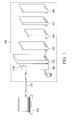
- FIG.1 illustrates an embodiment of the electronic system for performing a performance control process
- FIG.2 illustrates a schematic view of the electronic system
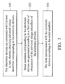
- FIG. 3 illustrates a flowchart of the management method of the invention.
- FIG.1 illustrates an embodiment of the electronic system.
- an electronic system 100 has electronic devices M1 ⁇ M6 and a control module CM.
- the control module CM can be disposed in one of the electronic devices M1 ⁇ M6 or in a host 120 coupled to the electronic system 100 through a transmission cable 130, but is not limited thereto.
- the electronic devices M1 ⁇ M6 are overlapped in a direction.
- each of the electronic devices M1 ⁇ M6 has a high speed transmission interface, e.g., a thunderbolt interface, such that the electronic devices M1 ⁇ M6 use a transport protocol compatible with a thunderbolt interface to communicate with a host 120.
- the electronic devices M1 ⁇ M6 are coupled in a daisy-chain configuration.
- each of the electronic devices M1 ⁇ M6 can be any of various kinds of peripheral devices.
- the electronic device M1 can be a TV box.
- the electronic device M2 can be an optical disk drive.
- the electronic device M3 can be a hard disk driver (HDD).
- the electronic device M4 can be a graphics processing unit (GPU) device.
- the electronic device M5 can be a speaker. Note that the number and the type of the electronic devices are provided for illustration, but are not limited thereto, any electronic device having the thunderbolt interface, any electronic device having interfaces faster than the thunderbolt interface or any electronic device coupled in the daisy-chain configuration can serve as the electronic device of the invention.
- FIG.2 illustrates a schematic view of the electronic system.
- the electronic devices M1 ⁇ M6 have switching units SW1 ⁇ SW6, respectively.
- the control module CM enables one of the electronic devices M1 ⁇ M6 to connect with a host in turn, thereby obtaining universal unique identifiers (UUID) corresponding to the electronic devices M1 ⁇ M6, and the control module CM generates serial numbers (e.g., NO1 ⁇ NO6) corresponding to the electronic devices M1 ⁇ M6 according to an order of obtainment of the universal unique identifiers of the electronic devices. Therefore, the users can give an instruction to the control module CM according to the serial numbers shown in the monitor, such that the host 120 communicates with the electronic devices M1 ⁇ M6 according to the serial numbers.
- UUID universal unique identifiers
- the electronic device M1 is electrically and directly connected to the host 120 through the transmission cable 130.
- the control module CM obtains a universal unique identifier UUID1 of the electronic device M1 of the electronic system 100, and generates a serial number NO1 corresponding to the electronic device M1 before the switching unit SW1 of the electronic device M1 is turned on, such that the switching unit SW1 operates in an close circuit state to determine whether another electronic device (e.g., electronic device M2) is electrically connected to the electronic device M1.
- another electronic device e.g., electronic device M2
- the control module CM determines that the electronic device M1 is the last sorted electronic device.
- the control module CM When the electronic device M2 is connected to the electronic device M1, the control module CM turns off the switching units SW1 and SW2, such that the switching units SW1 and SW2 operate in the open circuit state (the switching unit SW1 changes from the close circuit state to the open circuit state). Therefore, the control module CM only obtains the universal unique identifier UUID1 of the electronic device M1 of the electronic system 100, and generates a serial number NO1 corresponding to the electronic device M1 before the switching unit SW1 of the electronic device M1 is turned on, such that the switching unit SW1 operates in an close circuit state in order to determine whether another electronic device (e.g., electronic device M2) is electrically connected to the electronic device M1.
- another electronic device e.g., electronic device M2
- the control module CM can obtain a universal unique identifier UUID2 of the electronic device M2 of the electronic system 100 due to the connection between the electronic devices M2 and M1, and generates a serial number NO2 corresponding to the electronic device M2 before the switching unit SW2 of the electronic device M2 is turned on, such that it is determined whether another electronic device (e.g., electronic device M3) is electrically connected to the electronic device M2, wherein the electronic device M1 is electrically connected between the electronic device M2 and the host 120.
- another electronic device e.g., electronic device M3
- the control module CM determines that the electronic device M2 is the last sorted electronic device.
- the control module CM When the electronic device M3 is connected to the electronic device M2, the control module CM turns off the switching units SW1, SW2 and SW3, such that the switching units SW1, SW2 and SW3 operate in the open circuit state (the switching units SW1 and SW2 change from the close circuit state to the open circuit state). Therefore, the control module CM only obtains the universal unique identifier UUID1 of the electronic device M1 of the electronic system 100, and generates a serial number NO1 corresponding to the electronic device M1 before the switching unit SW1 of the electronic device M1 is turned on, such that the switching unit SW1 operates in the close circuit state in order to determine whether another electronic device (e.g., electronic device M2) is electrically connected to the electronic device M1.
- another electronic device e.g., electronic device M2
- the control module CM can obtain a universal unique identifier UUID2 of the electronic device M2 of the electronic system 100 due to the connection between the electronic devices M2 and M1, and generates a serial number NO2 corresponding to the electronic device M2 before the switching unit SW2 of the electronic device M2 is turned on, such that it is determined whether another electronic device (e.g., electronic device M3) is electrically connected to the electronic device M2.
- UUID2 universal unique identifier of the electronic device M2 of the electronic system 100 due to the connection between the electronic devices M2 and M1
- a serial number NO2 corresponding to the electronic device M2 before the switching unit SW2 of the electronic device M2 is turned on, such that it is determined whether another electronic device (e.g., electronic device M3) is electrically connected to the electronic device M2.
- the control module CM can obtain a universal unique identifier UUID3 of the electronic device M3 of the electronic system 100 due to the connection between the electronic devices M3 and M2, and generates a serial number NO3 corresponding to the electronic device M3 before the switching unit SW3 of the electronic device M3 is turned on, such that it is determined whether another electronic device (e.g., electronic device M4) is electrically connected to the electronic device M3, wherein the electronic device M2 is electrically connected between the electronic devices M1 and M3.
- the control module CM detects that there is no electronic device (e.g., electronic device M4) except for the electronic devices M1, M2 and M3, the control module CM determines that the electronic device M3 is the last sorted electronic device.
- the control module CM can display the information and the serial numbers NO1 ⁇ NO6 of the electronic devices M1 ⁇ M6 on the monitor, such that the user can select the desired electronic devices according to the serial numbers NO1 ⁇ NO6 and take away the desired electronic devices according to the order of the electronic devices M1 ⁇ M6.
- the electronic devices are hard disks and the user stores data in the electronic device M3 (the electronic device M3 is selected as the desired electronic device) having the serial number N03.
- the user When the user wants to head out or take away the electronic device which the data is stored in, the user only needs to take away the third electronic device (i.e., electronic device M3) of the electronic devices M1 ⁇ M6 rather than check all electronic devices one by one to find out which electronic device the data is stored in.
- electronic device M3 the third electronic device
- the arrangement order of the electronic devices M1 ⁇ M6 can serve as a password.
- a password (e.g., A11B22C33D44E55F66) is generated according to the order of the electronic devices M1 ⁇ M6 (M1, M2, M3, M4, M5, M6).
- the universal unique identifiers of the electronic devices are obtained and it is determined whether the order of obtainment of the universal unique identifiers of the electronic devices and the universal unique identifiers of the electronic devices are the same as the password, in order to unlock the electronic system.
- the first user sets the order (M1, M2, M6, M5, M4, M3) of the electronic devices as a password (e.g., A11B22C33F66E55D44) before going away.
- the second user changes the order of the electronic devices to another order (e.g., M1, M2, M3, M4, M5, M6) or takes one of the electronic devices away.
- the order of the electronic devices and the universal unique identifiers of the electronic devices are different from the password. Therefore, the second user can not open (or use) the electronic system unless the order of the electronic devices M1 ⁇ M6 and the universal unique identifiers of the electronic devices M1 ⁇ M6 are the same as the password.
- FIG. 3 illustrates a flowchart of the management method of the invention suitable for the electronic system 100 having the electronic devices (e.g., electronic devices M1 ⁇ M6) connected in a daisy-chain configuration.
- the management method includes the following steps.
- step S31 the electronic devices M1 ⁇ M6 are connected with the host 120 in turn, thereby obtaining universal unique identifiers UUID1 ⁇ UUID6 corresponding to the electronic devices M1 ⁇ M6.
- step S32 serial numbers corresponding to the electronic devices M1 ⁇ M6 are generated according to a first order of obtainment of the universal unique identifiers UUID1 ⁇ UUID6 of the electronic devices M1 ⁇ M6.
- step S33 the host 120 communicates with the electronic devices M1 ⁇ M6 according to the serial numbers
- the users can know which electronic devices are in use according to the serial numbers. Furthermore, the users can set a password according to the order and the universal unique identifiers of the electronic devices, thereby preventing the electronic devices from being misplaced.
Landscapes
- Engineering & Computer Science (AREA)
- Theoretical Computer Science (AREA)
- Physics & Mathematics (AREA)
- General Engineering & Computer Science (AREA)
- General Physics & Mathematics (AREA)
- Selective Calling Equipment (AREA)
- Small-Scale Networks (AREA)
- Lock And Its Accessories (AREA)
Abstract
Description
- This Application claims priority of Taiwan Patent Application No.
100137468, filed on Oct. 17, 2011 - The present invention relates to electronic systems, and in particular relates to electronic systems having thunderbolt interfaces.
- Recently, computers and networks have made many innovative functions more effective. New peripheral devices, such as internet units and external storage units, can easily be connected to computers or notebooks. However, there are various peripheral devices connected to the host (e.g., computer) and the user can not determine which peripheral device is currently being used. Thus, there is a need for an electronic system and a management method thereof to increase the convenience of usage.
- In light of the previously described problems, the invention provides an embodiment of a management method suitable for an electronic system having electronic devices connected in a daisy-chain configuration. The management method comprises the steps of: the electronic devices are sequentially connected with a host, thereby obtaining universal unique identifiers corresponding to the electronic devices; serial numbers corresponding to the electronic devices are generated according to a first order of obtainment of the universal unique identifiers of the electronic devices; and the host communicates with the electronic devices according to the serial numbers.
- The invention also provides an electronic system. An electronic system comprises a plurality of electronic devices and a control module. The electronic devices are connected in a daisy-chain configuration. The control module sequentially connects the electronic devices with a host to obtain universal unique identifiers corresponding to the electronic devices and generates serial numbers corresponding to the electronic devices according to a first order of obtainment of the universal unique identifiers of the electronic devices, thereby communicating with the electronic devices according to the serial numbers.
A detailed description is given in the following embodiments with reference to the accompanying drawings. - The present invention can be more fully understood by reading the subsequent detailed description and examples with references made to the accompanying drawings, wherein:
-
FIG.1 illustrates an embodiment of the electronic system for performing a performance control process; -
FIG.2 illustrates a schematic view of the electronic system; and -
FIG. 3 illustrates a flowchart of the management method of the invention. -
FIG.1 illustrates an embodiment of the electronic system. As shown inFIG. 1 , anelectronic system 100 has electronic devices M1∼M6 and a control module CM. In the embodiment, the control module CM can be disposed in one of the electronic devices M1∼M6 or in ahost 120 coupled to theelectronic system 100 through atransmission cable 130, but is not limited thereto. The electronic devices M1∼M6 are overlapped in a direction. In addition, each of the electronic devices M1∼M6 has a high speed transmission interface, e.g., a thunderbolt interface, such that the electronic devices M1∼M6 use a transport protocol compatible with a thunderbolt interface to communicate with ahost 120. The electronic devices M1∼M6 are coupled in a daisy-chain configuration. - In detail, each of the electronic devices M1∼M6 can be any of various kinds of peripheral devices. For example, the electronic device M1 can be a TV box. The electronic device M2 can be an optical disk drive. The electronic device M3 can be a hard disk driver (HDD). The electronic device M4 can be a graphics processing unit (GPU) device. The electronic device M5 can be a speaker. Note that the number and the type of the electronic devices are provided for illustration, but are not limited thereto, any electronic device having the thunderbolt interface, any electronic device having interfaces faster than the thunderbolt interface or any electronic device coupled in the daisy-chain configuration can serve as the electronic device of the invention.
-
FIG.2 illustrates a schematic view of the electronic system. As shown inFIG. 2 , the electronic devices M1∼M6 have switching units SW1∼SW6, respectively. The control module CM enables one of the electronic devices M1∼M6 to connect with a host in turn, thereby obtaining universal unique identifiers (UUID) corresponding to the electronic devices M1∼M6, and the control module CM generates serial numbers (e.g., NO1∼NO6) corresponding to the electronic devices M1∼M6 according to an order of obtainment of the universal unique identifiers of the electronic devices. Therefore, the users can give an instruction to the control module CM according to the serial numbers shown in the monitor, such that thehost 120 communicates with the electronic devices M1∼M6 according to the serial numbers. - For example, the electronic device M1 is electrically and directly connected to the
host 120 through thetransmission cable 130. The control module CM obtains a universal unique identifier UUID1 of the electronic device M1 of theelectronic system 100, and generates a serial number NO1 corresponding to the electronic device M1 before the switching unit SW1 of the electronic device M1 is turned on, such that the switching unit SW1 operates in an close circuit state to determine whether another electronic device (e.g., electronic device M2) is electrically connected to the electronic device M1. When the control module CM detects that there is no electronic device except for the electronic device M1, the control module CM determines that the electronic device M1 is the last sorted electronic device. - When the electronic device M2 is connected to the electronic device M1, the control module CM turns off the switching units SW1 and SW2, such that the switching units SW1 and SW2 operate in the open circuit state (the switching unit SW1 changes from the close circuit state to the open circuit state). Therefore, the control module CM only obtains the universal unique identifier UUID1 of the electronic device M1 of the
electronic system 100, and generates a serial number NO1 corresponding to the electronic device M1 before the switching unit SW1 of the electronic device M1 is turned on, such that the switching unit SW1 operates in an close circuit state in order to determine whether another electronic device (e.g., electronic device M2) is electrically connected to the electronic device M1. The control module CM can obtain a universal unique identifier UUID2 of the electronic device M2 of theelectronic system 100 due to the connection between the electronic devices M2 and M1, and generates a serial number NO2 corresponding to the electronic device M2 before the switching unit SW2 of the electronic device M2 is turned on, such that it is determined whether another electronic device (e.g., electronic device M3) is electrically connected to the electronic device M2, wherein the electronic device M1 is electrically connected between the electronic device M2 and thehost 120. When the control module CM detects that there is no electronic device except for the electronic devices M1 and M2, the control module CM determines that the electronic device M2 is the last sorted electronic device. - When the electronic device M3 is connected to the electronic device M2, the control module CM turns off the switching units SW1, SW2 and SW3, such that the switching units SW1, SW2 and SW3 operate in the open circuit state (the switching units SW1 and SW2 change from the close circuit state to the open circuit state). Therefore, the control module CM only obtains the universal unique identifier UUID1 of the electronic device M1 of the
electronic system 100, and generates a serial number NO1 corresponding to the electronic device M1 before the switching unit SW1 of the electronic device M1 is turned on, such that the switching unit SW1 operates in the close circuit state in order to determine whether another electronic device (e.g., electronic device M2) is electrically connected to the electronic device M1. The control module CM can obtain a universal unique identifier UUID2 of the electronic device M2 of theelectronic system 100 due to the connection between the electronic devices M2 and M1, and generates a serial number NO2 corresponding to the electronic device M2 before the switching unit SW2 of the electronic device M2 is turned on, such that it is determined whether another electronic device (e.g., electronic device M3) is electrically connected to the electronic device M2. The control module CM can obtain a universal unique identifier UUID3 of the electronic device M3 of theelectronic system 100 due to the connection between the electronic devices M3 and M2, and generates a serial number NO3 corresponding to the electronic device M3 before the switching unit SW3 of the electronic device M3 is turned on, such that it is determined whether another electronic device (e.g., electronic device M4) is electrically connected to the electronic device M3, wherein the electronic device M2 is electrically connected between the electronic devices M1 and M3. When the control module CM detects that there is no electronic device (e.g., electronic device M4) except for the electronic devices M1, M2 and M3, the control module CM determines that the electronic device M3 is the last sorted electronic device. - Details of the procedure of the other electronic devices (e.g., electronic devices M4∼M6) are similar to the procedure of the electronic devices M1∼M3, therefore, the details of the other electronic devices are omitted for brevity. The control module CM can display the information and the serial numbers NO1∼NO6 of the electronic devices M1∼M6 on the monitor, such that the user can select the desired electronic devices according to the serial numbers NO1∼NO6 and take away the desired electronic devices according to the order of the electronic devices M1∼M6. For example, assume that the electronic devices are hard disks and the user stores data in the electronic device M3 (the electronic device M3 is selected as the desired electronic device) having the serial number N03. When the user wants to head out or take away the electronic device which the data is stored in, the user only needs to take away the third electronic device (i.e., electronic device M3) of the electronic devices M1∼M6 rather than check all electronic devices one by one to find out which electronic device the data is stored in.
- In the embodiment, the arrangement order of the electronic devices M1∼M6 can serve as a password. In detail, a password (e.g., A11B22C33D44E55F66) is generated according to the order of the electronic devices M1∼M6 (M1, M2, M3, M4, M5, M6). When the electronic system is to be unlocked, the universal unique identifiers of the electronic devices are obtained and it is determined whether the order of obtainment of the universal unique identifiers of the electronic devices and the universal unique identifiers of the electronic devices are the same as the password, in order to unlock the electronic system. For example, the first user sets the order (M1, M2, M6, M5, M4, M3) of the electronic devices as a password (e.g., A11B22C33F66E55D44) before going away. The second user changes the order of the electronic devices to another order (e.g., M1, M2, M3, M4, M5, M6) or takes one of the electronic devices away. Thus, the order of the electronic devices and the universal unique identifiers of the electronic devices are different from the password. Therefore, the second user can not open (or use) the electronic system unless the order of the electronic devices M1∼M6 and the universal unique identifiers of the electronic devices M1∼M6 are the same as the password.
-
FIG. 3 illustrates a flowchart of the management method of the invention suitable for theelectronic system 100 having the electronic devices (e.g., electronic devices M1∼M6) connected in a daisy-chain configuration. As shown inFIG. 3 , the management method includes the following steps. - In step S31, the electronic devices M1∼M6 are connected with the
host 120 in turn, thereby obtaining universal unique identifiers UUID1∼UUID6 corresponding to the electronic devices M1∼M6. In step S32, serial numbers corresponding to the electronic devices M1∼M6 are generated according to a first order of obtainment of the universal unique identifiers UUID1∼UUID6 of the electronic devices M1∼M6. In step S33, thehost 120 communicates with the electronic devices M1∼M6 according to the serial numbers - Because the electronic devices M1∼M6 of the invention are coupled in the daisy chain configuration rather than in a tree-like configuration, the users can know which electronic devices are in use according to the serial numbers. Furthermore, the users can set a password according to the order and the universal unique identifiers of the electronic devices, thereby preventing the electronic devices from being misplaced.
- The foregoing has outlined features of several embodiments so that those skilled in the art may better understand the detailed description. Those skilled in the art should appreciate that they may readily use the present disclosure as a basis for designing or modifying other processes and structures for carrying out the same purposes and/or achieving the same advantages of the embodiments introduced herein. Those skilled in the art should also realize that such equivalent constructions do not depart from the spirit and scope of the present disclosure, and that they may make various changes, substitutions and alterations herein without departing from the spirit and scope of the present disclosure.
Claims (12)
- A management method, suitable for an electronic system having electronic devices connected in a daisy-chain configuration, comprising:connecting, sequentially, the electronic devices with a host, thereby obtaining universal unique identifiers corresponding to the electronic devices;generating serial numbers corresponding to the electronic devices according to a first order of obtainment of the universal unique identifiers of the electronic devices; andcommunicating with the electronic devices according to the serial numbers.
- The management method as claimed in claim 1, comprising:obtaining a universal unique identifier of a first electronic device of the electronic system, wherein the first electronic device is electrically connected to the host through a transmission cable;generating a first serial number corresponding to the first electronic device; andturning on a first switching unit of the first electronic device to detect whether a second electronic device is electrically connected to the host.
- The management method as claimed in claim 2, further comprising:obtaining a universal unique identifier of the second electronic device of the electronic system;generating a second serial number corresponding to the second electronic device; andturning on a second switching unit of the second electronic device to detect whether a third electronic device is electrically connected to the second electronic device, wherein the first electronic device is electrically connected between the host and the second electronic device.
- The management method as claimed in claim 1, further comprising:generating a password according to the first order and the serial numbers;obtaining the universal unique identifiers of the electronic devices when a lock of the electronic system is to be unlocked; anddetermining whether a second order of obtainment of the universal unique identifiers of the electronic devices and the universal unique identifiers of the electronic devices are the same as the password, thereby unlocking the lock of the electronic system.
- The management method as claimed in claim 1, wherein the electronic devices are overlapped in a direction and a transport protocol compatible with a thunderbolt interface is used to communicate with the host.
- The management method as claimed in claim 1, wherein the electronic devices have a graphics processing unit, a central processing unit, storage unit, a TV box and/or an optical disk drive.
- An electronic system, comprising:a plurality of electronic devices, connected in a daisy-chain configuration;a control module, connecting, sequentially, the electronic devices with a host to obtain universal unique identifiers corresponding to the electronic devices and generating serial numbers corresponding to the electronic devices according to a first order of obtainment of the universal unique identifiers of the electronic devices, thereby communicating with the electronic devices according to the serial numbers.
- The electronic system as claimed in claim 7, wherein the control module obtains a universal unique identifier of a first electronic device of the electronic system, and generates a first serial number corresponding to the first electronic device before a first switching unit of the first electronic device is turned on, in order to detect whether a second electronic device is electrically connected to the host.
- The electronic system as claimed in claim 7, wherein the control module obtains a universal unique identifier of a second electronic device of the electronic system, and generates a second serial number corresponding to the second electronic device before a second switching unit of the second electronic device is turned on, in order to detect whether a third electronic device is electrically connected to the second electronic device, wherein the first electronic device is electrically connected between the host and the second electronic device.
- The electronic system as claimed in claim 7, wherein the control module generates a password according to the first order and the serial numbers, and when the electronic system is to be unlocked, the control module obtains the universal unique identifiers of the electronic devices and determines whether a second order of obtainment of the universal unique identifiers of the electronic devices and the universal unique identifiers of the electronic devices are the same as the password, thereby unlocking the lock of the electronic system.
- The electronic system as claimed in claim 7, wherein the electronic devices are overlapped in a direction and a transport protocol compatible with a thunderbolt interface is used to communicate with the host.
- The electronic system as claimed in claim 7, wherein the electronic devices have a graphics processing unit, a central processing unit, storage unit, a TV box and/or an optical disk drive.
Applications Claiming Priority (1)
| Application Number | Priority Date | Filing Date | Title |
|---|---|---|---|
| TW100137468A TWI456406B (en) | 2011-10-17 | 2011-10-17 | Electronic systems and management methods |
Publications (2)
| Publication Number | Publication Date |
|---|---|
| EP2587386A1 true EP2587386A1 (en) | 2013-05-01 |
| EP2587386B1 EP2587386B1 (en) | 2015-04-22 |
Family
ID=47504585
Family Applications (1)
| Application Number | Title | Priority Date | Filing Date |
|---|---|---|---|
| EP20120188616 Active EP2587386B1 (en) | 2011-10-17 | 2012-10-16 | Electronic systems and management methods |
Country Status (3)
| Country | Link |
|---|---|
| US (1) | US8880741B2 (en) |
| EP (1) | EP2587386B1 (en) |
| TW (1) | TWI456406B (en) |
Families Citing this family (1)
| Publication number | Priority date | Publication date | Assignee | Title |
|---|---|---|---|---|
| TW201317791A (en) * | 2011-10-17 | 2013-05-01 | Acer Inc | Electronic devices and electronic systems |
Citations (2)
| Publication number | Priority date | Publication date | Assignee | Title |
|---|---|---|---|---|
| WO2007134444A1 (en) * | 2006-05-23 | 2007-11-29 | Mosaid Technologies Incorporated | Apparatus and method for establishing device identifiers for serially interconnected devices |
| WO2009078507A1 (en) * | 2007-12-17 | 2009-06-25 | Atlab Inc. | Serial communication system and id grant method thereof |
Family Cites Families (5)
| Publication number | Priority date | Publication date | Assignee | Title |
|---|---|---|---|---|
| US20020112070A1 (en) * | 2000-12-08 | 2002-08-15 | The Boeing Company | Network controller for digitally controlling remote devices via a common bus |
| US7961544B2 (en) * | 2008-08-05 | 2011-06-14 | Sandisk Il Ltd. | Storage system and method for managing a plurality of storage devices |
| US8312088B2 (en) * | 2009-07-27 | 2012-11-13 | Sandisk Il Ltd. | Device identifier selection |
| KR101468255B1 (en) * | 2010-11-22 | 2014-12-04 | 엘에스산전 주식회사 | PLC system |
| US8792879B2 (en) * | 2011-09-01 | 2014-07-29 | Scott A. Finberg | System and method of performing remote diagnostics on a computing device |
-
2011
- 2011-10-17 TW TW100137468A patent/TWI456406B/en not_active IP Right Cessation
-
2012
- 2012-10-12 US US13/650,412 patent/US8880741B2/en active Active
- 2012-10-16 EP EP20120188616 patent/EP2587386B1/en active Active
Patent Citations (2)
| Publication number | Priority date | Publication date | Assignee | Title |
|---|---|---|---|---|
| WO2007134444A1 (en) * | 2006-05-23 | 2007-11-29 | Mosaid Technologies Incorporated | Apparatus and method for establishing device identifiers for serially interconnected devices |
| WO2009078507A1 (en) * | 2007-12-17 | 2009-06-25 | Atlab Inc. | Serial communication system and id grant method thereof |
Also Published As
| Publication number | Publication date |
|---|---|
| TWI456406B (en) | 2014-10-11 |
| US20130097338A1 (en) | 2013-04-18 |
| EP2587386B1 (en) | 2015-04-22 |
| US8880741B2 (en) | 2014-11-04 |
| TW201317801A (en) | 2013-05-01 |
Similar Documents
| Publication | Publication Date | Title |
|---|---|---|
| US8812970B2 (en) | Dynamic device state representation in a user interface | |
| US8046536B2 (en) | Apparatus and method for managing a plurality of kinds of storage devices | |
| US9614678B2 (en) | System and method for extracting device uniqueness to assign a license to the device | |
| US20160259754A1 (en) | Hard disk drive form factor solid state drive multi-card adapter | |
| US8694693B2 (en) | Methods and systems for providing user selection of associations between information handling resources and information handling systems in an integrated chassis | |
| US8832327B1 (en) | Loading different device drivers for one device | |
| US7725613B2 (en) | Device installation with host controller consideration | |
| US9690745B2 (en) | Methods and systems for removal of information handling resources in a shared input/output infrastructure | |
| US7681007B2 (en) | Automatic expansion of hard disk drive capacity in a storage device | |
| US8135880B2 (en) | USB mass storage locking | |
| WO2014185948A1 (en) | Extraction of operating system-specific characteristics via a communication interface | |
| USRE42812E1 (en) | Apparatus for providing I/O support to a computer system and method of use thereof | |
| US8880741B2 (en) | Electronic systems and management methods | |
| US7533205B2 (en) | Control method and system of constructing raid configuration across multiple host bus adapters | |
| US7761540B2 (en) | System and method for automated remote booting in a serial attached SCSI environment | |
| CN103092780B (en) | Electronic system and management method | |
| TW201317802A (en) | Electronic systems and related host devices and management methods thereof | |
| US20230116864A1 (en) | Modular breakout cable | |
| EP2618265A1 (en) | Electronic systems and management methods | |
| US8209442B2 (en) | Peripheral device communicating with a specific website | |
| US20250335084A1 (en) | Touch screen operation modes | |
| US12432194B2 (en) | Secure peripheral management | |
| US20150042888A1 (en) | Switch apparatus and electronic device | |
| US9843477B2 (en) | Representation and control of the scope of impact in inherited settings | |
| JP2006338597A (en) | Data control system, program and electronic device |
Legal Events
| Date | Code | Title | Description |
|---|---|---|---|
| PUAI | Public reference made under article 153(3) epc to a published international application that has entered the european phase |
Free format text: ORIGINAL CODE: 0009012 |
|
| AK | Designated contracting states |
Kind code of ref document: A1 Designated state(s): AL AT BE BG CH CY CZ DE DK EE ES FI FR GB GR HR HU IE IS IT LI LT LU LV MC MK MT NL NO PL PT RO RS SE SI SK SM TR |
|
| AX | Request for extension of the european patent |
Extension state: BA ME |
|
| 17P | Request for examination filed |
Effective date: 20131030 |
|
| RBV | Designated contracting states (corrected) |
Designated state(s): AL AT BE BG CH CY CZ DE DK EE ES FI FR GB GR HR HU IE IS IT LI LT LU LV MC MK MT NL NO PL PT RO RS SE SI SK SM TR |
|
| RIC1 | Information provided on ipc code assigned before grant |
Ipc: G06F 13/42 20060101AFI20140930BHEP |
|
| GRAP | Despatch of communication of intention to grant a patent |
Free format text: ORIGINAL CODE: EPIDOSNIGR1 |
|
| INTG | Intention to grant announced |
Effective date: 20141204 |
|
| GRAS | Grant fee paid |
Free format text: ORIGINAL CODE: EPIDOSNIGR3 |
|
| GRAA | (expected) grant |
Free format text: ORIGINAL CODE: 0009210 |
|
| AK | Designated contracting states |
Kind code of ref document: B1 Designated state(s): AL AT BE BG CH CY CZ DE DK EE ES FI FR GB GR HR HU IE IS IT LI LT LU LV MC MK MT NL NO PL PT RO RS SE SI SK SM TR |
|
| REG | Reference to a national code |
Ref country code: GB Ref legal event code: FG4D |
|
| REG | Reference to a national code |
Ref country code: CH Ref legal event code: EP |
|
| REG | Reference to a national code |
Ref country code: AT Ref legal event code: REF Ref document number: 723600 Country of ref document: AT Kind code of ref document: T Effective date: 20150515 |
|
| REG | Reference to a national code |
Ref country code: IE Ref legal event code: FG4D |
|
| REG | Reference to a national code |
Ref country code: DE Ref legal event code: R096 Ref document number: 602012006834 Country of ref document: DE Effective date: 20150603 |
|
| REG | Reference to a national code |
Ref country code: NL Ref legal event code: VDEP Effective date: 20150422 |
|
| REG | Reference to a national code |
Ref country code: AT Ref legal event code: MK05 Ref document number: 723600 Country of ref document: AT Kind code of ref document: T Effective date: 20150422 |
|
| REG | Reference to a national code |
Ref country code: LT Ref legal event code: MG4D |
|
| PG25 | Lapsed in a contracting state [announced via postgrant information from national office to epo] |
Ref country code: NL Free format text: LAPSE BECAUSE OF FAILURE TO SUBMIT A TRANSLATION OF THE DESCRIPTION OR TO PAY THE FEE WITHIN THE PRESCRIBED TIME-LIMIT Effective date: 20150422 |
|
| PG25 | Lapsed in a contracting state [announced via postgrant information from national office to epo] |
Ref country code: NO Free format text: LAPSE BECAUSE OF FAILURE TO SUBMIT A TRANSLATION OF THE DESCRIPTION OR TO PAY THE FEE WITHIN THE PRESCRIBED TIME-LIMIT Effective date: 20150722 Ref country code: HR Free format text: LAPSE BECAUSE OF FAILURE TO SUBMIT A TRANSLATION OF THE DESCRIPTION OR TO PAY THE FEE WITHIN THE PRESCRIBED TIME-LIMIT Effective date: 20150422 Ref country code: PT Free format text: LAPSE BECAUSE OF FAILURE TO SUBMIT A TRANSLATION OF THE DESCRIPTION OR TO PAY THE FEE WITHIN THE PRESCRIBED TIME-LIMIT Effective date: 20150824 Ref country code: FI Free format text: LAPSE BECAUSE OF FAILURE TO SUBMIT A TRANSLATION OF THE DESCRIPTION OR TO PAY THE FEE WITHIN THE PRESCRIBED TIME-LIMIT Effective date: 20150422 Ref country code: LT Free format text: LAPSE BECAUSE OF FAILURE TO SUBMIT A TRANSLATION OF THE DESCRIPTION OR TO PAY THE FEE WITHIN THE PRESCRIBED TIME-LIMIT Effective date: 20150422 Ref country code: ES Free format text: LAPSE BECAUSE OF FAILURE TO SUBMIT A TRANSLATION OF THE DESCRIPTION OR TO PAY THE FEE WITHIN THE PRESCRIBED TIME-LIMIT Effective date: 20150422 |
|
| PG25 | Lapsed in a contracting state [announced via postgrant information from national office to epo] |
Ref country code: AT Free format text: LAPSE BECAUSE OF FAILURE TO SUBMIT A TRANSLATION OF THE DESCRIPTION OR TO PAY THE FEE WITHIN THE PRESCRIBED TIME-LIMIT Effective date: 20150422 Ref country code: GR Free format text: LAPSE BECAUSE OF FAILURE TO SUBMIT A TRANSLATION OF THE DESCRIPTION OR TO PAY THE FEE WITHIN THE PRESCRIBED TIME-LIMIT Effective date: 20150723 Ref country code: LV Free format text: LAPSE BECAUSE OF FAILURE TO SUBMIT A TRANSLATION OF THE DESCRIPTION OR TO PAY THE FEE WITHIN THE PRESCRIBED TIME-LIMIT Effective date: 20150422 Ref country code: IS Free format text: LAPSE BECAUSE OF FAILURE TO SUBMIT A TRANSLATION OF THE DESCRIPTION OR TO PAY THE FEE WITHIN THE PRESCRIBED TIME-LIMIT Effective date: 20150822 Ref country code: RS Free format text: LAPSE BECAUSE OF FAILURE TO SUBMIT A TRANSLATION OF THE DESCRIPTION OR TO PAY THE FEE WITHIN THE PRESCRIBED TIME-LIMIT Effective date: 20150422 |
|
| REG | Reference to a national code |
Ref country code: DE Ref legal event code: R097 Ref document number: 602012006834 Country of ref document: DE |
|
| PG25 | Lapsed in a contracting state [announced via postgrant information from national office to epo] |
Ref country code: DK Free format text: LAPSE BECAUSE OF FAILURE TO SUBMIT A TRANSLATION OF THE DESCRIPTION OR TO PAY THE FEE WITHIN THE PRESCRIBED TIME-LIMIT Effective date: 20150422 Ref country code: EE Free format text: LAPSE BECAUSE OF FAILURE TO SUBMIT A TRANSLATION OF THE DESCRIPTION OR TO PAY THE FEE WITHIN THE PRESCRIBED TIME-LIMIT Effective date: 20150422 |
|
| PLBE | No opposition filed within time limit |
Free format text: ORIGINAL CODE: 0009261 |
|
| STAA | Information on the status of an ep patent application or granted ep patent |
Free format text: STATUS: NO OPPOSITION FILED WITHIN TIME LIMIT |
|
| PG25 | Lapsed in a contracting state [announced via postgrant information from national office to epo] |
Ref country code: CZ Free format text: LAPSE BECAUSE OF FAILURE TO SUBMIT A TRANSLATION OF THE DESCRIPTION OR TO PAY THE FEE WITHIN THE PRESCRIBED TIME-LIMIT Effective date: 20150422 Ref country code: PL Free format text: LAPSE BECAUSE OF FAILURE TO SUBMIT A TRANSLATION OF THE DESCRIPTION OR TO PAY THE FEE WITHIN THE PRESCRIBED TIME-LIMIT Effective date: 20150422 Ref country code: SK Free format text: LAPSE BECAUSE OF FAILURE TO SUBMIT A TRANSLATION OF THE DESCRIPTION OR TO PAY THE FEE WITHIN THE PRESCRIBED TIME-LIMIT Effective date: 20150422 Ref country code: RO Free format text: LAPSE BECAUSE OF NON-PAYMENT OF DUE FEES Effective date: 20150422 |
|
| 26N | No opposition filed |
Effective date: 20160125 |
|
| PG25 | Lapsed in a contracting state [announced via postgrant information from national office to epo] |
Ref country code: IT Free format text: LAPSE BECAUSE OF FAILURE TO SUBMIT A TRANSLATION OF THE DESCRIPTION OR TO PAY THE FEE WITHIN THE PRESCRIBED TIME-LIMIT Effective date: 20150422 |
|
| PG25 | Lapsed in a contracting state [announced via postgrant information from national office to epo] |
Ref country code: SI Free format text: LAPSE BECAUSE OF FAILURE TO SUBMIT A TRANSLATION OF THE DESCRIPTION OR TO PAY THE FEE WITHIN THE PRESCRIBED TIME-LIMIT Effective date: 20150422 Ref country code: LU Free format text: LAPSE BECAUSE OF FAILURE TO SUBMIT A TRANSLATION OF THE DESCRIPTION OR TO PAY THE FEE WITHIN THE PRESCRIBED TIME-LIMIT Effective date: 20151016 |
|
| REG | Reference to a national code |
Ref country code: CH Ref legal event code: PL |
|
| PG25 | Lapsed in a contracting state [announced via postgrant information from national office to epo] |
Ref country code: MC Free format text: LAPSE BECAUSE OF FAILURE TO SUBMIT A TRANSLATION OF THE DESCRIPTION OR TO PAY THE FEE WITHIN THE PRESCRIBED TIME-LIMIT Effective date: 20150422 |
|
| REG | Reference to a national code |
Ref country code: IE Ref legal event code: MM4A |
|
| PG25 | Lapsed in a contracting state [announced via postgrant information from national office to epo] |
Ref country code: CH Free format text: LAPSE BECAUSE OF NON-PAYMENT OF DUE FEES Effective date: 20151031 Ref country code: LI Free format text: LAPSE BECAUSE OF NON-PAYMENT OF DUE FEES Effective date: 20151031 |
|
| REG | Reference to a national code |
Ref country code: FR Ref legal event code: ST Effective date: 20160630 |
|
| PG25 | Lapsed in a contracting state [announced via postgrant information from national office to epo] |
Ref country code: BE Free format text: LAPSE BECAUSE OF FAILURE TO SUBMIT A TRANSLATION OF THE DESCRIPTION OR TO PAY THE FEE WITHIN THE PRESCRIBED TIME-LIMIT Effective date: 20150422 Ref country code: FR Free format text: LAPSE BECAUSE OF NON-PAYMENT OF DUE FEES Effective date: 20151102 |
|
| PG25 | Lapsed in a contracting state [announced via postgrant information from national office to epo] |
Ref country code: IE Free format text: LAPSE BECAUSE OF NON-PAYMENT OF DUE FEES Effective date: 20151016 |
|
| PG25 | Lapsed in a contracting state [announced via postgrant information from national office to epo] |
Ref country code: BG Free format text: LAPSE BECAUSE OF FAILURE TO SUBMIT A TRANSLATION OF THE DESCRIPTION OR TO PAY THE FEE WITHIN THE PRESCRIBED TIME-LIMIT Effective date: 20150422 Ref country code: SM Free format text: LAPSE BECAUSE OF FAILURE TO SUBMIT A TRANSLATION OF THE DESCRIPTION OR TO PAY THE FEE WITHIN THE PRESCRIBED TIME-LIMIT Effective date: 20150422 Ref country code: HU Free format text: LAPSE BECAUSE OF FAILURE TO SUBMIT A TRANSLATION OF THE DESCRIPTION OR TO PAY THE FEE WITHIN THE PRESCRIBED TIME-LIMIT; INVALID AB INITIO Effective date: 20121016 |
|
| GBPC | Gb: european patent ceased through non-payment of renewal fee |
Effective date: 20161016 |
|
| PG25 | Lapsed in a contracting state [announced via postgrant information from national office to epo] |
Ref country code: CY Free format text: LAPSE BECAUSE OF FAILURE TO SUBMIT A TRANSLATION OF THE DESCRIPTION OR TO PAY THE FEE WITHIN THE PRESCRIBED TIME-LIMIT Effective date: 20150422 Ref country code: SE Free format text: LAPSE BECAUSE OF FAILURE TO SUBMIT A TRANSLATION OF THE DESCRIPTION OR TO PAY THE FEE WITHIN THE PRESCRIBED TIME-LIMIT Effective date: 20150422 |
|
| PG25 | Lapsed in a contracting state [announced via postgrant information from national office to epo] |
Ref country code: GB Free format text: LAPSE BECAUSE OF NON-PAYMENT OF DUE FEES Effective date: 20161016 |
|
| PG25 | Lapsed in a contracting state [announced via postgrant information from national office to epo] |
Ref country code: MT Free format text: LAPSE BECAUSE OF FAILURE TO SUBMIT A TRANSLATION OF THE DESCRIPTION OR TO PAY THE FEE WITHIN THE PRESCRIBED TIME-LIMIT Effective date: 20150422 |
|
| PG25 | Lapsed in a contracting state [announced via postgrant information from national office to epo] |
Ref country code: MK Free format text: LAPSE BECAUSE OF FAILURE TO SUBMIT A TRANSLATION OF THE DESCRIPTION OR TO PAY THE FEE WITHIN THE PRESCRIBED TIME-LIMIT Effective date: 20150422 Ref country code: TR Free format text: LAPSE BECAUSE OF FAILURE TO SUBMIT A TRANSLATION OF THE DESCRIPTION OR TO PAY THE FEE WITHIN THE PRESCRIBED TIME-LIMIT Effective date: 20150422 |
|
| PG25 | Lapsed in a contracting state [announced via postgrant information from national office to epo] |
Ref country code: AL Free format text: LAPSE BECAUSE OF FAILURE TO SUBMIT A TRANSLATION OF THE DESCRIPTION OR TO PAY THE FEE WITHIN THE PRESCRIBED TIME-LIMIT Effective date: 20150422 |
|
| PGFP | Annual fee paid to national office [announced via postgrant information from national office to epo] |
Ref country code: DE Payment date: 20240925 Year of fee payment: 13 |