EP2587290A1 - Optical connector - Google Patents
Optical connector Download PDFInfo
- Publication number
- EP2587290A1 EP2587290A1 EP11798208.2A EP11798208A EP2587290A1 EP 2587290 A1 EP2587290 A1 EP 2587290A1 EP 11798208 A EP11798208 A EP 11798208A EP 2587290 A1 EP2587290 A1 EP 2587290A1
- Authority
- EP
- European Patent Office
- Prior art keywords
- housing
- optical fiber
- sleeve
- optical connector
- optical
- Prior art date
- Legal status (The legal status is an assumption and is not a legal conclusion. Google has not performed a legal analysis and makes no representation as to the accuracy of the status listed.)
- Withdrawn
Links
Images




Classifications
-
- G—PHYSICS
- G02—OPTICS
- G02B—OPTICAL ELEMENTS, SYSTEMS OR APPARATUS
- G02B6/00—Light guides; Structural details of arrangements comprising light guides and other optical elements, e.g. couplings
- G02B6/24—Coupling light guides
- G02B6/36—Mechanical coupling means
- G02B6/38—Mechanical coupling means having fibre to fibre mating means
- G02B6/3807—Dismountable connectors, i.e. comprising plugs
- G02B6/3887—Anchoring optical cables to connector housings, e.g. strain relief features
- G02B6/38875—Protection from bending or twisting
-
- G—PHYSICS
- G02—OPTICS
- G02B—OPTICAL ELEMENTS, SYSTEMS OR APPARATUS
- G02B6/00—Light guides; Structural details of arrangements comprising light guides and other optical elements, e.g. couplings
- G02B6/24—Coupling light guides
- G02B6/36—Mechanical coupling means
-
- G—PHYSICS
- G02—OPTICS
- G02B—OPTICAL ELEMENTS, SYSTEMS OR APPARATUS
- G02B6/00—Light guides; Structural details of arrangements comprising light guides and other optical elements, e.g. couplings
- G02B6/24—Coupling light guides
- G02B6/36—Mechanical coupling means
- G02B6/38—Mechanical coupling means having fibre to fibre mating means
-
- G—PHYSICS
- G02—OPTICS
- G02B—OPTICAL ELEMENTS, SYSTEMS OR APPARATUS
- G02B6/00—Light guides; Structural details of arrangements comprising light guides and other optical elements, e.g. couplings
- G02B6/24—Coupling light guides
- G02B6/36—Mechanical coupling means
- G02B6/38—Mechanical coupling means having fibre to fibre mating means
- G02B6/3807—Dismountable connectors, i.e. comprising plugs
- G02B6/381—Dismountable connectors, i.e. comprising plugs of the ferrule type, e.g. fibre ends embedded in ferrules, connecting a pair of fibres
- G02B6/3826—Dismountable connectors, i.e. comprising plugs of the ferrule type, e.g. fibre ends embedded in ferrules, connecting a pair of fibres characterised by form or shape
- G02B6/3829—Bent or angled connectors
-
- G—PHYSICS
- G02—OPTICS
- G02B—OPTICAL ELEMENTS, SYSTEMS OR APPARATUS
- G02B6/00—Light guides; Structural details of arrangements comprising light guides and other optical elements, e.g. couplings
- G02B6/24—Coupling light guides
- G02B6/36—Mechanical coupling means
- G02B6/38—Mechanical coupling means having fibre to fibre mating means
- G02B6/3807—Dismountable connectors, i.e. comprising plugs
- G02B6/3869—Mounting ferrules to connector body, i.e. plugs
- G02B6/387—Connector plugs comprising two complementary members, e.g. shells, caps, covers, locked together
-
- G—PHYSICS
- G02—OPTICS
- G02B—OPTICAL ELEMENTS, SYSTEMS OR APPARATUS
- G02B6/00—Light guides; Structural details of arrangements comprising light guides and other optical elements, e.g. couplings
- G02B6/24—Coupling light guides
- G02B6/36—Mechanical coupling means
- G02B6/38—Mechanical coupling means having fibre to fibre mating means
- G02B6/3807—Dismountable connectors, i.e. comprising plugs
- G02B6/3873—Connectors using guide surfaces for aligning ferrule ends, e.g. tubes, sleeves, V-grooves, rods, pins, balls
- G02B6/3874—Connectors using guide surfaces for aligning ferrule ends, e.g. tubes, sleeves, V-grooves, rods, pins, balls using tubes, sleeves to align ferrules
- G02B6/3878—Connectors using guide surfaces for aligning ferrule ends, e.g. tubes, sleeves, V-grooves, rods, pins, balls using tubes, sleeves to align ferrules comprising a plurality of ferrules, branching and break-out means
-
- G—PHYSICS
- G02—OPTICS
- G02B—OPTICAL ELEMENTS, SYSTEMS OR APPARATUS
- G02B6/00—Light guides; Structural details of arrangements comprising light guides and other optical elements, e.g. couplings
- G02B6/24—Coupling light guides
- G02B6/36—Mechanical coupling means
- G02B6/38—Mechanical coupling means having fibre to fibre mating means
- G02B6/3807—Dismountable connectors, i.e. comprising plugs
- G02B6/3887—Anchoring optical cables to connector housings, e.g. strain relief features
- G02B6/3888—Protection from over-extension or over-compression
Definitions
- the present invention relates to an optical connector used in connection between optical fibers in, for example, a LAN for an automobile.
- the wire harness including the optical fiber cable has a configuration that an optical connector is connected to a terminal of the optical fiber cable (see, Patent Document 1, for example).
- a plug frame holding a ferrule which is fixed to optical fiber strands drawn out from the optical fiber cable is accommodated in a housing and a stop ring fixing a tensile strength fiber of the optical fiber cable and an outer skin is connected to the plug frame by a crimping ring.
- Patent Document 1 JP-A-2010-26475
- the present invention has been made to solve the above-described problems and an object of the present invention is to provide an optical connector having an excellent assembling workability.
- the optical connector according to the present invention is characterized by the following (1) to (3).
- the sleeve to which the covering part is fixed can be very easily fixed to the housing and thus it is possible to significantly improve the assembling workability. By doing so, even in a case where the housing is replaced and repaired due to damage of the housing or the ferrule assembly is recombined to other different type of housing, it is possible to easily detach the ferrule assembly from the housing and to assemble the ferrule assembly to new housing.
- the irregularities are formed at the outer periphery of the sleeve, the irregularities serve as a slippage prevention part when the ring is fitted onto the sleeve. In this way, it is possible to firmly fix the covering part which has the tensile strength fiber to the sleeve.
- the optical fiber strands can be smoothly bent toward the ferrules in the insertion through-hole, even if the ferrules are placed at a position offset from the axis of the sleeve in the housing. In this way, the optical fiber strands are not sharply bent and thus increase in transmission loss can be suppressed.
- the optical fiber strands are smoothly bent toward the ferrules in the insertion through-hole, it is possible to minimize the distance between the sleeve and the ferrules, even in a structure where the ferrules are placed at a position offset from the axis of the sleeve. As a result, the compactness of the housing can be achieved.
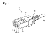
- an optical connector 11 is a male connector which is mounted on a leading end of an optical fiber cable 12.
- the optical connector 11 is fitted and connected to a female optical connector which is a mating connector.
- the optical connector 11 includes a housing 21, a ferrule assembly 31 which is provided at a leading end of the optical fiber cable 12 and accommodated in the housing 21, a leaf spring member 41 mounted to the housing 21 and a retainer 51 assembled to the housing 21.
- the housing 21 is molded from a synthetic resin such as plastic. As shown in FIG. 4 , a leading end side of the housing is a ferrule mounting part 23 which is provided with a pair of through-holes 22 penetrating in a front-rear direction. Ferrules 61 constituting the ferrule assembly 31 are inserted thorough theses through-holes 22 from the rear side.
- the housing 21 is provided at its rear end side with a component mounting part 24 which is opened at an upper side as one side, that is, a lateral side of the housing 21.
- the leaf spring member 41 is mounted to the component mounting part 24.
- the leaf spring member 41 is formed from spring steel and includes a connection part 42 which is formed in a waveform as seen from a side view.
- One end of the connection part 42 of the leaf spring member 41 is a support piece portion 43 and the other end of the connection part 42 is a biased piece portion 44.
- the leaf spring member 41 thus configured is mounted to the component mounting part 24 of the housing 21 on which the ferrules 61 are mounted. Then, the leaf spring member 41 is disposed between a wall portion 24a formed at the component mounting part 24 of the housing 21 and the ferrules 61. The support piece portion 43 is brought into contact with the wall portion 24a and the biased piece portion 44 is brought into contact with a rear end of the ferrules 61. In this way, the ferrules 61 are held at the housing 21 in a state of being biased toward a leading end of the housing 21 by the leaf spring member 41.
- the ferrules 61 of the optical connector 11 and the ferrules of the mating optical connector are biased and brought into contact with each other and thus a good optical connection state is achieved.
- the retainer 51 which is assembled to the component mounting part 24 of the housing 21 is molded from a synthetic resin such as plastic.
- the retainer 51 includes a pressing plate portion 52 which has substantially the same outer shape as an opening portion of the component mounting part 24 and locking pieces 53 formed at both sides of the pressing plate portion 52.
- the locking pieces 53 are projected toward a mounting direction to the component mounting part 24 of the housing 21.
- Each of the locking pieces 53 is formed with a locking claw 54 projecting outward.
- the retainer 51 As the retainer 51 thus configured is assembled to the component mounting part 24 of the housing 21, the component mounting part 24 of the housing 21 is closed by the pressing plate portion 52. Further, at this time, the locking claws 54 of the locking pieces 53 are engaged with the edge of locking holes 24c which are formed at both side walls 24b of the housing 21. As a result, the retainer 51 is securely assembled to the housing 21.
- a surface of the retainer 51 at a side of the mounting direction to the component mounting part 24 serves as a holding portion 55 to hold the leaf spring member 41. Accordingly, the retainer 51 can be attached and detached from the component mounting part 24 of the housing 21 in a state where the leaf spring member 41 is held at the holding portion 55.
- the optical fiber cable 12 having the ferrule assembly 31 at its leading end includes two optical fiber strands 15 which are obtained by covering a glass fiber 13 consisting of a core and a clad with an outer skin 14. These two optical fiber strands 15 are covered with the covering part 16.
- the covering part 16 has a configuration that a tensile strength fiber (tensile strength material) 18 such as an aramid fiber, for example, is provided inside a covering layer 17 formed from resin.
- optical fiber cable 12 is subjected to a terminal processing and thus the optical fiber strands 15 are exposed from the covering part 16.
- the ferrule assembly 31 provided at the leading end of the optical fiber cable 12 includes the ferrules 61, a crimping sleeve (sleeve) 71, a crimping ring (ring) 81 and a boot 91.
- the ferrules 61 are formed from a metal such as brass and a fiber insertion through-hole 62 is formed at the center of the ferrule.
- the optical fiber strands 15 exposed from the covering part 16 are inserted though the fiber insertion through-hole 62 from the rear end side.
- a leading end side of the fiber insertion through-hole 62 is serves as a glass fiber holding hole portion 62a.
- the glass fiber 13 exposed from the outer skin 14 of the optical fiber strands 15 is inserted into the glass fiber holding hole portion 62a and then fixed thereto by an adhesive, etc.
- Flanges 61 a, 61 b are formed at the middle and rear end of the ferrules 61 in a longitudinal direction. And, as the ferrules 61 are inserted through the though-hole 22 formed at the ferrule mounting part 23 of the housing 21, a holding protrusion 26 formed at the housing 21 enters between the flanges 61 a, 61 b of the ferrules 61, so that the ferrules 61 are held in a state being inserted into the though-hole 22.
- the crimping sleeve 71 includes a cylindrical sleeve portion 73 which is provided at its center with an insertion through-hole 72 and a flange portion 74 which is formed at a leading end side of the sleeve portion 73.
- the flange portion 74 has a rectangular shape as seen from a plan view.
- the flange portion 74 of the crimping sleeve 71 is accommodated into a recessed receiving part (receiving part) 24d formed at the component mounting part 24 of the housing 21 from the upper side of the housing 21 which is an opening side of the component mounting part 24.
- the housing 21 is formed at its rear end with a hole portion 24e which is communicated with the component mounting part 24.
- the sleeve potion 73 of the crimping sleeve 71 in a state where the flange portion 74 is accommodated into the recessed receiving part 24d is projected from the hole portion 24e to the rear of the housing 21.
- the optical fiber strands 15 exposed from the covering part 16 are inserted through the insertion through-hole 72 of the sleeve portion 73 of the crimping sleeve 71 from the rear end side.
- the insertion through-hole 72 has a diameter which is gradually enlarged from the vicinity of the rear end toward a leading end of the optical fiber strands 15 in an insertion direction.
- the insertion through-hole 72 includes a same diameter hole section 72a in a range from the rear end to the vicinity of the rear end, a first diameter enlarged hole section 72b in a range from the vicinity of the rear end to the vicinity of the leading end and a second diameter enlarged hole section 72c in a range from the vicinity of the leading end to the leading end.
- the same diameter hole section 72a has the same diameter.
- the first diameter enlarged hole section 72b has a diameter which is gently enlarged.
- the second diameter enlarged hole section 72c has a diameter which is enlarged at a proportion rapider than the first diameter enlarged hole section 72b. Accordingly, as the optical fiber strands 15 inserted through the insertion through-hole 72 are bent outward in a radial direction, the optical fiber strands 15 are bent outward in the radial direction along the first diameter enlarged hole section 72b and also bent outward in the radial direction along the second diameter enlarged hole section 72c. In this way, the optical fiber strands 15 can be smoothly bent outward in the radial direction in a stepwise manner within the insertion through-hole 72.
- a plurality of engaging grooves 75 are formed along the circumferential direction at intervals in an axial direction. Accordingly, irregularities consisting of the plurality of engaging grooves 75 are formed at an outer peripheral surface of the sleeve portion 73. Further, a chamfered portion 76 is formed at an outer peripheral side edge of a rear end of the sleeve portion 73.
- An outer periphery of the sleeve portion 73 of the crimping sleeve 71 is covered with the covering part 16 which consists of the tensile strength fiber 18 and the cover layer 17 of the optical fiber cable 12.
- a cylindrical crimping ring 81 is fitted onto the sleeve portion 73.
- An end of the covering part 16 which consists of the tensile strength fiber 18 and the cover layer 17 of the optical fiber cable 12 and is covering the sleeve portion 73 is sandwiched and fixed between the sleeve portion 73 and the crimping ring 81.
- the boot 91 is, for example, formed from an elastic resin material such as rubber and is provided with a cable insertion through-hole 92. Further, engaging pieces 93 are projected from both sides of one end of the boot 91. These engaging pieces 93 are formed with engaging claws 94 projecting outward.
- the optical fiber cable 12 is inserted through the cable insertion through-hole 92 of the boot 91. Further, the engaging pieces 93 of the boot 91 are inserted into engaging holes 25 which are formed at a rear end surface of the housing 21. The engaging claws 94 are engaged with engaging windows 25a which are formed at a side of the engaging holes 25. Therefore, the boot 91 is fixed to a rear end of the housing 21 and covers and protects the optical fiber cable 12 which is drawn out from the rear end of the housing 21. In this way, an excessive bending is prevented.
- the ferrule assembly 31 having the above-described structure may be mounted to a housing which constitutes other different type of optical connector.
- FIG. 7 shows an optical connector 111 made of a relay connector. Also in this optical connector 111, a component mounting part 124 is formed at a housing 121 thereof. Further, a retainer 151 can be attached and detached from the component mounting part 124.
- the ferrules 61 of the ferrule assembly 31 are equipped at its leading end with split sleeves 112 and accommodated into the housing 121 through the component mounting part 124. Further, the component mounting part 124 of the housing 121 is also provided with a recessed receiving part 124d which is opened at a lateral side. The flange portion 74 of the crimping sleeve 71 constituting the ferrule assembly 31 is slid and accommodated into the recessed receiving part and thus held in the housing 121.
- the ferrule assembly 31 can be easily assembled to a housing of various optical connectors since the ferrule assembly is common for various different types of optical connector such as a PCB board connector without being limited to the above-described relay connector.
- the boot 91, the crimping ring 81 and the crimping sleeve 71 are previously inserted along the optical fiber cable 12 and the optical fiber strands 15 are fixed to the ferrules 61 by an adhesive, etc. and then the leading end surface of the ferrules 61 is polished.
- the sleeve portion 73 of the crimping sleeve 71 is covered with an end of the covering part 16 and the crimping ring 81 is fitted onto the sleeve portion 73.
- the plurality of engaging grooves 75 are formed along the circumferential direction at intervals in the axial direction and therefore irregularities are formed. Accordingly, when the crimping ring 81 is fitted onto the sleeve portion 73, the irregularities consisting of the plurality of engaging grooves 75 serve to prevent slippage of the covering part 16 which consists of the cover layer 17 and the tensile strength fiber 18. In this way, it is possible to firmly fix the covering part 16 to the crimping sleeve 71.
- the ferrule assembly 31 is assembled to the housing 21. Specifically, the ferrules 61 are inserted through the though-hole 22 formed at the ferrule mounting part 23 of the housing 21 and the flange portion 74 of the crimping sleeve 71 is slid and accommodated into the recessed receiving part 24d formed at the component mounting part 24 of the housing 21 from the lateral side which is an upper side of the housing 21.
- the crimping sleeve 71 to which the covering part 16 of the optical fiber cable 12 is fixed can be very easily fixed to the housing 21. Further, since the flange portion 74 of the crimping sleeve 71 has a rectangular shape as seen from a plan view and thus secures a large area, the crimping sleeve can be fixed to the housing 21 with a large fixed intensity.
- each of the ferrules 61 inserted through the though-hole 22 of the ferrule mounting part 23 are spaced apart from each other in the housing 21, each of the ferrules 61 is disposed at a position offset from the axis of the crimping sleeve 71. Accordingly, the optical fiber strands 15 drawn out from the covering part 16 are spaced apart from each other toward the end and thus bent. In this case, when the distance between the crimping sleeve 71 and the ferrules 61 is short, the optical fiber strands 15 are sharply bent and thus increase in transmission loss is caused.
- the crimping sleeve 71 of the present embodiment is configured in such a way that the insertion through-hole 72 of the sleeve portion 73 has a diameter which is gradually enlarged toward the insertion direction of the optical fiber strands 15, the optical fiber strands 15 can be smoothly bent outward in the radial direction in the insertion through-hole 72 (see, FIG. 6 ). Accordingly, even when the distance between the crimping sleeve 71 and the ferrules 61 is short, the optical fiber strands 15 are not sharply bent and thus increase in transmission loss is suppressed.
- each of the optical fiber strands 15 is a plastic-clad-silica (PCS) fiber which includes a core made of quartz glass and a clad made of resin, a bending radius thereof can be reduced below R9 which is an allowable bending radius.
- PCS plastic-clad-silica
- the boot 91 is moved toward the housing 21 and thus the engaging pieces 93 of the boot are inserted into the engaging holes 25 of the housing 21. And then, the engaging claws 94 are engaged with the engaging windows 25a and therefore the boot is fixed to a rear end of the housing 21 (see, FIG. 4 ).
- the leaf spring member 41 is disposed between the wall portion 24a of the component mounting part 24 and the ferrules 61, the support piece portion 43 is brought into contact with the wall portion 24a and the biased piece portion 44 is brought into contact with the rear end of the ferrules 61. In this way, the ferrules 61 are biased toward the leading end of the housing 21 by the leaf spring member 41.
- the ferrule assembly 31 is detached from the housing 21.
- the engagement with the locking claws 54 of the retainer 51 is released, the retainer 51 is detached together with the leaf spring member 41 from the housing 21 and thus the boot 91 is detached from the housing 21.
- the crimping sleeve 71 is slid and pulled upward from the housing 21. In this way, the flange portion 74 is withdrawn from the recessed receiving part 24d and the ferrules 61 are withdrawn from the through-hole 22 of the ferrule mounting part 23.
- the optical connector according to the present embodiment has a configuration that the housing 21 is formed with the recessed receiving part 24d which is opened at the lateral side and the crimping sleeve 71 is formed with the flange portion 74 which can be slid and accommodated into the recessed receiving part 24d. Accordingly, since the flange portion 74 of the crimping sleeve 71 is slid and accommodated into the recessed receiving part 24d from the lateral side of the housing 21, the crimping sleeve 71 to which the covering part 16 is fixed can be very easily fixed to the housing 21 and thus it is possible to significantly improve the assembling workability.
- the irregularities consisting of the plurality of engaging grooves 75 are formed at the outer peripheral surface of the sleeve portion 73 of the crimping sleeve 71, the irregularities serve as a slippage prevention part when the crimping ring 81 is fitted onto the sleeve portion. In this way, it is possible to firmly fix the covering part 16 which has the cover layer 17 and the tensile strength fiber 18 to the crimping sleeve 71.
- the insertion through-hole 72 of the crimping sleeve 71 through which the optical fiber strands 15 pass has a diameter which is gradually enlarged toward the insertion direction of the optical fiber strands 15, the optical fiber strands 15 can be smoothly bent toward the ferrules 61 in the insertion through-hole 72, even if the ferrules 61 are placed at a position offset from the axis of the crimping sleeve 71 in the housing 21. In this way, the optical fiber strands 15 are not sharply bent and thus increase in transmission loss can be suppressed.
- the optical fiber strands 15 are smoothly bent toward the ferrules 61 in the insertion through-hole 72, it is possible to minimize the distance between the crimping sleeve 71 and the ferrules 61, even in a structure where the ferrules 61 are placed at a position offset from the axis of the crimping sleeve 71. As a result, the compactness of the housing 21 can be achieved.
- the flange portion 74 of the crimping sleeve 71 has a rectangular shape as seen from a plan view in the foregoing embodiment
- the shape of the flange portion 74 as seen from the plan view is not limited to the rectangular shape, but may be a circular shape, etc.
- the size of the flange portion 74 is reduced and thus the compactness of the crimping sleeve 71 and the housing 21 can be achieved.
- the irregularities consisting of the plurality of engaging grooves 75 are formed at the outer peripheral surface of the sleeve portion 73 of the crimping sleeve 71 in the foregoing embodiment, a plurality of protrusions may be formed or a plurality of holes may be formed, for example. Further, the insertion through-hole 72 of the crimping sleeve 71 may have a diameter which is enlarged in a curved shape as seen from a cross-sectional view.
- FIG. 9 is a perspective view of an optical connector according to a reference example and FIG. 10 is an exploded perspective view of the optical connector according to the reference example.
- the optical connector 1 includes a lower housing 2, an upper housing 3 and a boot 4.
- the upper housing 3 is integrally mounted to the lower housing 2 to cover the lower housing in which the ferrule 61 is accommodated.
- the lower housing 2 is formed integrally with a cylindrical crimping sleeve 2a through which the optical fiber strands 15 is inserted.
- a crimping ring 5 is fitted onto the crimping sleeve 2a in a state of being covered with the covering part 16 of the optical fiber cable 12.
- the boot 4 is formed with a cover portion 4a. A portion of the lower housing 2 and the upper housing 3 which are integrated is covered with the cover portion 4a.
- the lower housing 2 is formed integrally with the crimping sleeve 2a. Accordingly, when it is necessary to replace the lower housing 2 for repairing the lower housing or for employing different type of connector, for example, a detachment work is required as follows. First, the crimping ring 5 is removed and thus the covering part 16 is detached from the crimping sleeve 2a. And then, the ferrules 61 are detached from the optical fiber strands 15 and thus the optical fiber strands 15 are detached from the crimping sleeve 2a.
- optical connector of the present invention has been explained in detail with reference to the particular embodiment, the present invention is not limited to each of the above-described embodiments and various modifications and alternations may be made. Further, the material, shape and dimensions of each component constituting the optical connector of the present invention may be arbitrarily selected as long as the object of the present invention can be achieved and are not limited to each of the above-described embodiments.
- This application is based upon Japanese Patent Application (Patent Application No. 2010-142758 ) filed on June 23, 2010 and the entire contents of which are incorporated herein by reference.
- the optical connector which has an excellent assembling workability. Accordingly, even in a case where the housing is replaced and repaired or the ferrule assembly is recombined to other different type of housing, it is possible to easily detach the ferrule assembly from the housing and to assemble the ferrule assembly to new housing.
Landscapes
- Physics & Mathematics (AREA)
- General Physics & Mathematics (AREA)
- Optics & Photonics (AREA)
- Mechanical Coupling Of Light Guides (AREA)
Abstract
Description
- The present invention relates to an optical connector used in connection between optical fibers in, for example, a LAN for an automobile.
- Recently, in order to suppress increase in the number of circuit and to reduce noise, a wire harness including an optical fiber cable which is partially covered with an optical fiber has been used for an automobile.
- The wire harness including the optical fiber cable has a configuration that an optical connector is connected to a terminal of the optical fiber cable (see, Patent Document 1, for example).
- In the conventional optical connector, a plug frame holding a ferrule which is fixed to optical fiber strands drawn out from the optical fiber cable is accommodated in a housing and a stop ring fixing a tensile strength fiber of the optical fiber cable and an outer skin is connected to the plug frame by a crimping ring.
- Patent Document 1:
JP-A-2010-26475 - However, in the above-described optical connector, it is necessary to perform a complicated assembling work that the ferrule fixed to the optical fiber strands is mounted to the plug frame, the stop ring fixing the tensile strength fiber of the optical fiber cable and the outer skin is assembled to the plug frame and then the plug frame is accommodated into the housing.
- Accordingly, a great deal of effort is expended to perform a detachment work and an assembling work when the ferrule to which the optical fiber strands are connected is recombined into the plug frame and the housing which constitutes another optical fiber connector for repairing the optical connector or replacing the optical connector with different type of connector.
- The present invention has been made to solve the above-described problems and an object of the present invention is to provide an optical connector having an excellent assembling workability.
- In order to achieve the above-described object, the optical connector according to the present invention is characterized by the following (1) to (3).
- (1) An optical connector is connected to an end portion of an optical fiber cable that is obtained by covering optical fiber strands with a covering part that has a tensile strength material, the optical connector includes:
- a ferrule which is fixed to an end portion of the optical fiber strands exposed from the covering part,
- a sleeve through which the optical fiber strands pass and to which the covering part is fixed and,
- a housing in which the ferrule and the sleeve are held and,
- the housing includes a receiving part which is opened at a lateral side and the sleeve includes a flange portion which can be accommodated in the receiving part by being slid thereinto from the lateral side of the housing.
- (2) In the optical connector of the above configuration (1), the covering part is fixed to the sleeve by covering an outer periphery of the sleeve with an end of the covering part and fitting a ring thereon and the sleeve is provided at its outer peripheral surface with irregularities.
- (3) In the optical connector of the above configuration (1) or (2), the sleeve is provided with an insertion through-hole through which the optical fiber strands pass and the insertion through-hole has a diameter which is gradually enlarged toward the insertion direction of the optical fiber strands.
- According to the optical connector of the above configuration (1), since the flange portion of the sleeve is slid and accommodated into the receiving part from the lateral side of the housing, the sleeve to which the covering part is fixed can be very easily fixed to the housing and thus it is possible to significantly improve the assembling workability.
By doing so, even in a case where the housing is replaced and repaired due to damage of the housing or the ferrule assembly is recombined to other different type of housing, it is possible to easily detach the ferrule assembly from the housing and to assemble the ferrule assembly to new housing.
According to the optical connector of the above configuration (2), since the irregularities are formed at the outer periphery of the sleeve, the irregularities serve as a slippage prevention part when the ring is fitted onto the sleeve. In this way, it is possible to firmly fix the covering part which has the tensile strength fiber to the sleeve.
According to the optical connector of the above configuration (3), since the insertion through-hole of the sleeve through which the optical fiber strands pass has a diameter which is gradually enlarged toward the insertion direction of the optical fiber strands, the optical fiber strands can be smoothly bent toward the ferrules in the insertion through-hole, even if the ferrules are placed at a position offset from the axis of the sleeve in the housing. In this way, the optical fiber strands are not sharply bent and thus increase in transmission loss can be suppressed. Further, since the optical fiber strands are smoothly bent toward the ferrules in the insertion through-hole, it is possible to minimize the distance between the sleeve and the ferrules, even in a structure where the ferrules are placed at a position offset from the axis of the sleeve. As a result, the compactness of the housing can be achieved. - Hereinabove, the present invention has been described briefly. In addition, the detailed configurations of the present invention will be clarified by reading through the mode for carrying out the invention as described below, with reference to the accompanying drawings.
-
-
FIG. 1 is a perspective view of an optical connector according to an illustrative embodiment of the present invention. -
FIG. 2 is an exploded perspective view of the optical connector shown inFIG. 1 . -
FIG. 3 is an exploded side view of the optical connector shown inFIG. 1 . -
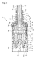
FIG. 4 is a cross-sectional plan view of the optical connector shown inFIG. 1 . -
FIG. 5 is a perspective view of a crimping sleeve shown inFIG. 4 . -
FIG. 6 is a cross-sectional view of the crimping sleeve shown inFIG. 4 . -
FIG. 7 is an exploded perspective view of the optical connector according to another embodiment of the present invention. -
FIG. 8 (a) and FIG. 8 (b) are views for explaining a process of assembling the optical connector, respectively showing a side view of the optical connector during assembling. -
FIG. 9 is a perspective view of an optical connector according to a reference example. -
FIG. 10 is an exploded perspective view of the optical connector according to the reference example shown inFIG. 9 . - Hereinafter, an example of an illustrative embodiment according to the present invention will be described with reference to the accompanying drawings.
- As shown in
FIGS. 1 and2 , anoptical connector 11 according to an illustrative embodiment of the present invention is a male connector which is mounted on a leading end of anoptical fiber cable 12. Theoptical connector 11 is fitted and connected to a female optical connector which is a mating connector. - As also shown in
FIG. 3 , theoptical connector 11 includes ahousing 21, aferrule assembly 31 which is provided at a leading end of theoptical fiber cable 12 and accommodated in thehousing 21, aleaf spring member 41 mounted to thehousing 21 and aretainer 51 assembled to thehousing 21. - The
housing 21 is molded from a synthetic resin such as plastic. As shown inFIG. 4 , a leading end side of the housing is aferrule mounting part 23 which is provided with a pair of through-holes 22 penetrating in a front-rear direction.Ferrules 61 constituting theferrule assembly 31 are inserted thorough theses through-holes 22 from the rear side. - Further, the
housing 21 is provided at its rear end side with acomponent mounting part 24 which is opened at an upper side as one side, that is, a lateral side of thehousing 21. Theleaf spring member 41 is mounted to thecomponent mounting part 24. - The
leaf spring member 41 is formed from spring steel and includes aconnection part 42 which is formed in a waveform as seen from a side view. One end of theconnection part 42 of theleaf spring member 41 is asupport piece portion 43 and the other end of theconnection part 42 is abiased piece portion 44. - The
leaf spring member 41 thus configured is mounted to thecomponent mounting part 24 of thehousing 21 on which theferrules 61 are mounted. Then, theleaf spring member 41 is disposed between awall portion 24a formed at thecomponent mounting part 24 of thehousing 21 and theferrules 61. Thesupport piece portion 43 is brought into contact with thewall portion 24a and thebiased piece portion 44 is brought into contact with a rear end of theferrules 61. In this way, theferrules 61 are held at thehousing 21 in a state of being biased toward a leading end of thehousing 21 by theleaf spring member 41. - Accordingly, as the
optical connector 11 is connected to the mating optical connector, theferrules 61 of theoptical connector 11 and the ferrules of the mating optical connector are biased and brought into contact with each other and thus a good optical connection state is achieved. - The
retainer 51 which is assembled to thecomponent mounting part 24 of thehousing 21 is molded from a synthetic resin such as plastic. Theretainer 51 includes apressing plate portion 52 which has substantially the same outer shape as an opening portion of thecomponent mounting part 24 andlocking pieces 53 formed at both sides of thepressing plate portion 52. Thelocking pieces 53 are projected toward a mounting direction to thecomponent mounting part 24 of thehousing 21. Each of thelocking pieces 53 is formed with alocking claw 54 projecting outward. - As the
retainer 51 thus configured is assembled to thecomponent mounting part 24 of thehousing 21, thecomponent mounting part 24 of thehousing 21 is closed by thepressing plate portion 52. Further, at this time, thelocking claws 54 of thelocking pieces 53 are engaged with the edge oflocking holes 24c which are formed at bothside walls 24b of thehousing 21. As a result, theretainer 51 is securely assembled to thehousing 21. - A surface of the
retainer 51 at a side of the mounting direction to thecomponent mounting part 24 serves as a holdingportion 55 to hold theleaf spring member 41. Accordingly, theretainer 51 can be attached and detached from thecomponent mounting part 24 of thehousing 21 in a state where theleaf spring member 41 is held at the holdingportion 55. - The
optical fiber cable 12 having theferrule assembly 31 at its leading end includes twooptical fiber strands 15 which are obtained by covering aglass fiber 13 consisting of a core and a clad with anouter skin 14. These twooptical fiber strands 15 are covered with the coveringpart 16. The coveringpart 16 has a configuration that a tensile strength fiber (tensile strength material) 18 such as an aramid fiber, for example, is provided inside acovering layer 17 formed from resin. - And, the
optical fiber cable 12 is subjected to a terminal processing and thus theoptical fiber strands 15 are exposed from the coveringpart 16. - The
ferrule assembly 31 provided at the leading end of theoptical fiber cable 12 includes theferrules 61, a crimping sleeve (sleeve) 71, a crimping ring (ring) 81 and aboot 91. - The
ferrules 61 are formed from a metal such as brass and a fiber insertion through-hole 62 is formed at the center of the ferrule. Theoptical fiber strands 15 exposed from the coveringpart 16 are inserted though the fiber insertion through-hole 62 from the rear end side. A leading end side of the fiber insertion through-hole 62 is serves as a glass fiber holdinghole portion 62a. Theglass fiber 13 exposed from theouter skin 14 of theoptical fiber strands 15 is inserted into the glass fiber holdinghole portion 62a and then fixed thereto by an adhesive, etc. -
Flanges ferrules 61 in a longitudinal direction. And, as theferrules 61 are inserted through the though-hole 22 formed at theferrule mounting part 23 of thehousing 21, a holdingprotrusion 26 formed at thehousing 21 enters between theflanges ferrules 61, so that theferrules 61 are held in a state being inserted into the though-hole 22. - As shown in
FIGS. 5 and 6 , the crimpingsleeve 71 includes acylindrical sleeve portion 73 which is provided at its center with an insertion through-hole 72 and aflange portion 74 which is formed at a leading end side of thesleeve portion 73. Theflange portion 74 has a rectangular shape as seen from a plan view. - The
flange portion 74 of the crimpingsleeve 71 is accommodated into a recessed receiving part (receiving part) 24d formed at thecomponent mounting part 24 of thehousing 21 from the upper side of thehousing 21 which is an opening side of thecomponent mounting part 24. Thehousing 21 is formed at its rear end with ahole portion 24e which is communicated with thecomponent mounting part 24. Thesleeve potion 73 of the crimpingsleeve 71 in a state where theflange portion 74 is accommodated into the recessed receivingpart 24d is projected from thehole portion 24e to the rear of thehousing 21. - The
optical fiber strands 15 exposed from the coveringpart 16 are inserted through the insertion through-hole 72 of thesleeve portion 73 of the crimpingsleeve 71 from the rear end side. The insertion through-hole 72 has a diameter which is gradually enlarged from the vicinity of the rear end toward a leading end of theoptical fiber strands 15 in an insertion direction. Specifically, the insertion through-hole 72 includes a samediameter hole section 72a in a range from the rear end to the vicinity of the rear end, a first diameter enlargedhole section 72b in a range from the vicinity of the rear end to the vicinity of the leading end and a second diameter enlargedhole section 72c in a range from the vicinity of the leading end to the leading end. The samediameter hole section 72a has the same diameter. The first diameter enlargedhole section 72b has a diameter which is gently enlarged. The second diameter enlargedhole section 72c has a diameter which is enlarged at a proportion rapider than the first diameter enlargedhole section 72b. Accordingly, as theoptical fiber strands 15 inserted through the insertion through-hole 72 are bent outward in a radial direction, theoptical fiber strands 15 are bent outward in the radial direction along the first diameter enlargedhole section 72b and also bent outward in the radial direction along the second diameter enlargedhole section 72c. In this way, theoptical fiber strands 15 can be smoothly bent outward in the radial direction in a stepwise manner within the insertion through-hole 72. - At an outer peripheral surface of the
sleeve portion 73 of the crimpingsleeve 71, a plurality of engaginggrooves 75 are formed along the circumferential direction at intervals in an axial direction. Accordingly, irregularities consisting of the plurality of engaginggrooves 75 are formed at an outer peripheral surface of thesleeve portion 73. Further, a chamferedportion 76 is formed at an outer peripheral side edge of a rear end of thesleeve portion 73. - An outer periphery of the
sleeve portion 73 of the crimpingsleeve 71 is covered with the coveringpart 16 which consists of thetensile strength fiber 18 and thecover layer 17 of theoptical fiber cable 12. - A cylindrical crimping
ring 81 is fitted onto thesleeve portion 73. An end of the coveringpart 16 which consists of thetensile strength fiber 18 and thecover layer 17 of theoptical fiber cable 12 and is covering thesleeve portion 73 is sandwiched and fixed between thesleeve portion 73 and the crimpingring 81. - The
boot 91 is, for example, formed from an elastic resin material such as rubber and is provided with a cable insertion through-hole 92. Further, engagingpieces 93 are projected from both sides of one end of theboot 91. These engagingpieces 93 are formed with engagingclaws 94 projecting outward. - The
optical fiber cable 12 is inserted through the cable insertion through-hole 92 of theboot 91. Further, the engagingpieces 93 of theboot 91 are inserted into engagingholes 25 which are formed at a rear end surface of thehousing 21. The engagingclaws 94 are engaged withengaging windows 25a which are formed at a side of the engaging holes 25. Therefore, theboot 91 is fixed to a rear end of thehousing 21 and covers and protects theoptical fiber cable 12 which is drawn out from the rear end of thehousing 21. In this way, an excessive bending is prevented. - The
ferrule assembly 31 having the above-described structure may be mounted to a housing which constitutes other different type of optical connector. -
FIG. 7 shows anoptical connector 111 made of a relay connector. Also in thisoptical connector 111, acomponent mounting part 124 is formed at ahousing 121 thereof. Further, aretainer 151 can be attached and detached from thecomponent mounting part 124. - The
ferrules 61 of theferrule assembly 31 are equipped at its leading end withsplit sleeves 112 and accommodated into thehousing 121 through thecomponent mounting part 124. Further, thecomponent mounting part 124 of thehousing 121 is also provided with a recessed receivingpart 124d which is opened at a lateral side. Theflange portion 74 of the crimpingsleeve 71 constituting theferrule assembly 31 is slid and accommodated into the recessed receiving part and thus held in thehousing 121. - In this way, the
ferrule assembly 31 can be easily assembled to a housing of various optical connectors since the ferrule assembly is common for various different types of optical connector such as a PCB board connector without being limited to the above-described relay connector. - Next, a case of assembling the
optical connector 11 is described. - First, in order to assemble the
ferrule assembly 31, as shown inFIG. 8 (a), theboot 91, the crimpingring 81 and the crimpingsleeve 71 are previously inserted along theoptical fiber cable 12 and theoptical fiber strands 15 are fixed to theferrules 61 by an adhesive, etc. and then the leading end surface of theferrules 61 is polished. - Next, the
sleeve portion 73 of the crimpingsleeve 71 is covered with an end of the coveringpart 16 and the crimpingring 81 is fitted onto thesleeve portion 73. - Here, at the outer peripheral surface of the
sleeve portion 73 of the crimpingsleeve 71, the plurality of engaginggrooves 75 are formed along the circumferential direction at intervals in the axial direction and therefore irregularities are formed. Accordingly, when the crimpingring 81 is fitted onto thesleeve portion 73, the irregularities consisting of the plurality of engaginggrooves 75 serve to prevent slippage of the coveringpart 16 which consists of thecover layer 17 and thetensile strength fiber 18. In this way, it is possible to firmly fix the coveringpart 16 to the crimpingsleeve 71. - After the
ferrule assembly 31 is assembled as mentioned above, theferrule assembly 31 is assembled to thehousing 21. Specifically, theferrules 61 are inserted through the though-hole 22 formed at theferrule mounting part 23 of thehousing 21 and theflange portion 74 of the crimpingsleeve 71 is slid and accommodated into the recessed receivingpart 24d formed at thecomponent mounting part 24 of thehousing 21 from the lateral side which is an upper side of thehousing 21. In this way, as theflange portion 74 of the crimpingsleeve 71 is slid and accommodated into the recessed receivingpart 24d of thehousing 21, the crimpingsleeve 71 to which the coveringpart 16 of theoptical fiber cable 12 is fixed can be very easily fixed to thehousing 21. Further, since theflange portion 74 of the crimpingsleeve 71 has a rectangular shape as seen from a plan view and thus secures a large area, the crimping sleeve can be fixed to thehousing 21 with a large fixed intensity. - Here, since the
ferrules 61 inserted through the though-hole 22 of theferrule mounting part 23 are spaced apart from each other in thehousing 21, each of theferrules 61 is disposed at a position offset from the axis of the crimpingsleeve 71. Accordingly, theoptical fiber strands 15 drawn out from the coveringpart 16 are spaced apart from each other toward the end and thus bent. In this case, when the distance between the crimpingsleeve 71 and theferrules 61 is short, theoptical fiber strands 15 are sharply bent and thus increase in transmission loss is caused. However, since the crimpingsleeve 71 of the present embodiment is configured in such a way that the insertion through-hole 72 of thesleeve portion 73 has a diameter which is gradually enlarged toward the insertion direction of theoptical fiber strands 15, theoptical fiber strands 15 can be smoothly bent outward in the radial direction in the insertion through-hole 72 (see,FIG. 6 ). Accordingly, even when the distance between the crimpingsleeve 71 and theferrules 61 is short, theoptical fiber strands 15 are not sharply bent and thus increase in transmission loss is suppressed. For example, in a case where each of theoptical fiber strands 15 is a plastic-clad-silica (PCS) fiber which includes a core made of quartz glass and a clad made of resin, a bending radius thereof can be reduced below R9 which is an allowable bending radius. - After the crimping
sleeve 71 is mounted, theboot 91 is moved toward thehousing 21 and thus the engagingpieces 93 of the boot are inserted into the engagingholes 25 of thehousing 21. And then, the engagingclaws 94 are engaged with the engagingwindows 25a and therefore the boot is fixed to a rear end of the housing 21 (see,FIG. 4 ). - In this way, when the
ferrule assembly 31 is assembled to thehousing 21, theretainer 51 whose holdingportion 55 holds theleaf spring member 41 is assembled to thecomponent mounting part 24 of thehousing 21 from the upper side thereof, as shown inFIG. 8 (a) . Then, the lockingclaws 54 of the lockingpieces 53 of theretainer 51 are engaged with the edge of lockingholes 24c of bothside walls 24b of thehousing 21 and thus theretainer 51 is securely assembled to thehousing 21. And, thecomponent mounting part 24 of thehousing 21 is closed by thepressing plate portion 52 of theretainer 51 and thus detachment of theleaf spring member 41, theferrules 61 and the crimpingsleeve 71 from thecomponent mounting part 24 is prevented. - Further, the
leaf spring member 41 is disposed between thewall portion 24a of thecomponent mounting part 24 and theferrules 61, thesupport piece portion 43 is brought into contact with thewall portion 24a and thebiased piece portion 44 is brought into contact with the rear end of theferrules 61. In this way, theferrules 61 are biased toward the leading end of thehousing 21 by theleaf spring member 41. - Here, in a case where the
housing 21 is replaced and repaired due to damage or the ferrule assembly is recombined to thehousing 121 of theoptical connector 111 such as the above-described relay connector, theferrule assembly 31 is detached from thehousing 21. In this case, first, the engagement with the lockingclaws 54 of theretainer 51 is released, theretainer 51 is detached together with theleaf spring member 41 from thehousing 21 and thus theboot 91 is detached from thehousing 21. And then, the crimpingsleeve 71 is slid and pulled upward from thehousing 21. In this way, theflange portion 74 is withdrawn from the recessed receivingpart 24d and theferrules 61 are withdrawn from the through-hole 22 of theferrule mounting part 23. - Hereinabove, as described above, the optical connector according to the present embodiment has a configuration that the
housing 21 is formed with the recessed receivingpart 24d which is opened at the lateral side and the crimpingsleeve 71 is formed with theflange portion 74 which can be slid and accommodated into the recessed receivingpart 24d. Accordingly, since theflange portion 74 of the crimpingsleeve 71 is slid and accommodated into the recessed receivingpart 24d from the lateral side of thehousing 21, the crimpingsleeve 71 to which the coveringpart 16 is fixed can be very easily fixed to thehousing 21 and thus it is possible to significantly improve the assembling workability. - By doing so, even in a case where the
housing 21 is replaced and repaired due to damage of thehousing 21 or the ferrule assembly is recombined to other different type ofhousing 121, it is possible to easily detach the ferrule assembly from thehousing 21 and to assemble the ferrule assembly tonew housing - Further, since the irregularities consisting of the plurality of engaging
grooves 75 are formed at the outer peripheral surface of thesleeve portion 73 of the crimpingsleeve 71, the irregularities serve as a slippage prevention part when the crimpingring 81 is fitted onto the sleeve portion. In this way, it is possible to firmly fix the coveringpart 16 which has thecover layer 17 and thetensile strength fiber 18 to the crimpingsleeve 71. - Further, since the insertion through-
hole 72 of the crimpingsleeve 71 through which theoptical fiber strands 15 pass has a diameter which is gradually enlarged toward the insertion direction of theoptical fiber strands 15, theoptical fiber strands 15 can be smoothly bent toward theferrules 61 in the insertion through-hole 72, even if theferrules 61 are placed at a position offset from the axis of the crimpingsleeve 71 in thehousing 21. In this way, theoptical fiber strands 15 are not sharply bent and thus increase in transmission loss can be suppressed. Further, since theoptical fiber strands 15 are smoothly bent toward theferrules 61 in the insertion through-hole 72, it is possible to minimize the distance between the crimpingsleeve 71 and theferrules 61, even in a structure where theferrules 61 are placed at a position offset from the axis of the crimpingsleeve 71. As a result, the compactness of thehousing 21 can be achieved. - In addition, although the
flange portion 74 of the crimpingsleeve 71 has a rectangular shape as seen from a plan view in the foregoing embodiment, the shape of theflange portion 74 as seen from the plan view is not limited to the rectangular shape, but may be a circular shape, etc. In particular, when theflange portion 74 has the circular shape, the size of theflange portion 74 is reduced and thus the compactness of the crimpingsleeve 71 and thehousing 21 can be achieved. - Further, although the irregularities consisting of the plurality of engaging
grooves 75 are formed at the outer peripheral surface of thesleeve portion 73 of the crimpingsleeve 71 in the foregoing embodiment, a plurality of protrusions may be formed or a plurality of holes may be formed, for example.
Further, the insertion through-hole 72 of the crimpingsleeve 71 may have a diameter which is enlarged in a curved shape as seen from a cross-sectional view. - Now, in order to explain the advantages of the present invention, a reference example is described with reference to
FIGS. 9 and10 . -
FIG. 9 is a perspective view of an optical connector according to a reference example andFIG. 10 is an exploded perspective view of the optical connector according to the reference example. - As shown in
FIGS. 9 and10 , the optical connector 1 according to the reference example includes alower housing 2, anupper housing 3 and aboot 4. Theupper housing 3 is integrally mounted to thelower housing 2 to cover the lower housing in which theferrule 61 is accommodated. Thelower housing 2 is formed integrally with a cylindrical crimpingsleeve 2a through which theoptical fiber strands 15 is inserted. A crimping ring 5 is fitted onto the crimpingsleeve 2a in a state of being covered with the coveringpart 16 of theoptical fiber cable 12. Theboot 4 is formed with acover portion 4a. A portion of thelower housing 2 and theupper housing 3 which are integrated is covered with thecover portion 4a. - In this optical connector 1, the
lower housing 2 is formed integrally with the crimpingsleeve 2a. Accordingly, when it is necessary to replace thelower housing 2 for repairing the lower housing or for employing different type of connector, for example, a detachment work is required as follows. First, the crimping ring 5 is removed and thus the coveringpart 16 is detached from the crimpingsleeve 2a. And then, theferrules 61 are detached from theoptical fiber strands 15 and thus theoptical fiber strands 15 are detached from the crimpingsleeve 2a. In addition, after that, an assembling work is performed in such a way that theoptical fiber strands 15 are inserted through the crimpingsleeve 2a of newlower housing 2 and then theferrules 61 are fixed, and the crimpingsleeve 2a is covered with the coveringpart 16 and fixed by fitting the crimping ring 5 thereon.
That is, according to the optical connector 1 having the above-described structure, a very complicated detachment work and assembling work are required for the replacement of thelower housing 2. - Although the optical connector of the present invention has been explained in detail with reference to the particular embodiment, the present invention is not limited to each of the above-described embodiments and various modifications and alternations may be made. Further, the material, shape and dimensions of each component constituting the optical connector of the present invention may be arbitrarily selected as long as the object of the present invention can be achieved and are not limited to each of the above-described embodiments.
This application is based upon Japanese Patent Application (Patent Application No.2010-142758 - According to the present invention, it is possible to provide the optical connector which has an excellent assembling workability. Accordingly, even in a case where the housing is replaced and repaired or the ferrule assembly is recombined to other different type of housing, it is possible to easily detach the ferrule assembly from the housing and to assemble the ferrule assembly to new housing.
-
- 11, 111
- Optical connector
- 12
- Optical fiber cable
- 15
- Optical fiber strand
- 16
- Covering part
- 18
- Tensile strength fiber (Tensile strength material)
- 21, 121
- Housing
- 24d, 124d
- Recessed receiving part (Receiving part)
- 61
- Ferrule
- 71
- Crimping sleeve (Sleeve)
- 72
- Insertion through-hole
- 74
- Flange portion
- 75
- Engagement groove
- 81
- Crimping ring (Ring)
Claims (3)
- An optical connector connected to an end portion of an optical fiber cable that is obtained by covering an optical fiber strand with a covering part that has a tensile strength material, the optical connector comprising:a ferrule fixed to an end portion of the optical fiber strand exposed from the covering part,a sleeve through which the optical fiber strand pass and to which the covering part is fixed and,a housing in which the ferrule and the sleeve are held,wherein the housing includes a receiving part opened at a lateral side and the sleeve includes a flange portion which can be accommodated in the receiving part by being slid thereinto from the lateral side of the housing.
- The optical connector according to claim 1, wherein the covering part is fixed to the sleeve by covering an outer periphery of the sleeve with an end of the covering part and fitting a ring thereon and the sleeve is provided at its outer peripheral surface with irregularities.
- The optical connector according to claim 1 or 2, wherein the sleeve is provided with an insertion through-hole through which the optical fiber strands pass and the insertion through-hole has a diameter which is gradually enlarged toward the insertion direction of the optical fiber strands.
Applications Claiming Priority (2)
| Application Number | Priority Date | Filing Date | Title |
|---|---|---|---|
| JP2010142758A JP5599237B2 (en) | 2010-06-23 | 2010-06-23 | Optical connector |
| PCT/JP2011/064368 WO2011162327A1 (en) | 2010-06-23 | 2011-06-23 | Optical connector |
Publications (2)
| Publication Number | Publication Date |
|---|---|
| EP2587290A1 true EP2587290A1 (en) | 2013-05-01 |
| EP2587290A4 EP2587290A4 (en) | 2017-10-11 |
Family
ID=45371499
Family Applications (1)
| Application Number | Title | Priority Date | Filing Date |
|---|---|---|---|
| EP11798208.2A Withdrawn EP2587290A4 (en) | 2010-06-23 | 2011-06-23 | Optical connector |
Country Status (5)
| Country | Link |
|---|---|
| US (1) | US20130101258A1 (en) |
| EP (1) | EP2587290A4 (en) |
| JP (1) | JP5599237B2 (en) |
| KR (1) | KR101422991B1 (en) |
| WO (1) | WO2011162327A1 (en) |
Cited By (1)
| Publication number | Priority date | Publication date | Assignee | Title |
|---|---|---|---|---|
| EP2801850B1 (en) * | 2013-05-10 | 2024-11-20 | Yazaki Corporation | Optical connector |
Families Citing this family (44)
| Publication number | Priority date | Publication date | Assignee | Title |
|---|---|---|---|---|
| JP5582413B2 (en) * | 2011-03-23 | 2014-09-03 | 日立金属株式会社 | Cable with connector |
| JP2012220731A (en) * | 2011-04-08 | 2012-11-12 | Yazaki Corp | Optical connector |
| JP5812335B2 (en) * | 2011-10-12 | 2015-11-11 | 株式会社オートネットワーク技術研究所 | Optical connector |
| WO2013104125A1 (en) * | 2012-01-12 | 2013-07-18 | 3M Innovative Properties Company | Field mountable duplex optical fiber connector with mechanical splice elements |
| JP5882765B2 (en) * | 2012-02-02 | 2016-03-09 | 矢崎総業株式会社 | Optical connector |
| JP5898510B2 (en) * | 2012-02-03 | 2016-04-06 | 矢崎総業株式会社 | Optical connector |
| JP5873760B2 (en) * | 2012-05-25 | 2016-03-01 | 矢崎総業株式会社 | Optical connector |
| JP6122291B2 (en) | 2012-08-10 | 2017-04-26 | 矢崎総業株式会社 | Optical connector and optical connector assembling method |
| JP6077797B2 (en) * | 2012-08-30 | 2017-02-08 | 矢崎総業株式会社 | Optical connector |
| JP6068881B2 (en) * | 2012-09-04 | 2017-01-25 | 矢崎総業株式会社 | Optical connector |
| WO2014085462A1 (en) | 2012-11-30 | 2014-06-05 | Tyco Electronics Corporation | Fiber optic connector with field installable outer connector housing |
| JP6085471B2 (en) | 2012-12-21 | 2017-02-22 | 矢崎総業株式会社 | Optical connector |
| JP6272649B2 (en) * | 2013-02-15 | 2018-01-31 | 矢崎総業株式会社 | Optical connector |
| JP6267875B2 (en) * | 2013-06-04 | 2018-01-24 | 矢崎総業株式会社 | Optical connector |
| US12368615B2 (en) | 2013-09-19 | 2025-07-22 | Radius Universal Llc | Fiber optic communications and power network |
| US10139569B2 (en) * | 2016-04-05 | 2018-11-27 | Radius Universal, LLC | Connector assemblies for hybrid fiber/wire connections |
| US10277330B2 (en) | 2013-09-19 | 2019-04-30 | Radius Universal Llc | Fiber optic communications and power network |
| CN104849816B (en) | 2014-02-14 | 2017-01-11 | 泰科电子(上海)有限公司 | Optical fiber connector and assembly method therefor |
| CN104849815B (en) | 2014-02-14 | 2017-01-18 | 泰科电子(上海)有限公司 | Optical fiber connector and assembly method therefor |
| US9297964B2 (en) * | 2014-04-18 | 2016-03-29 | Senko Advanced Components, Inc. | Optical fiber connector assembly |
| CN105445862B (en) | 2014-07-09 | 2018-01-19 | 泰科电子(上海)有限公司 | The joints of optical fibre and its on-site assembly method |
| US10620385B2 (en) | 2015-11-30 | 2020-04-14 | Commscope Technologies Llc | Fiber optic connector and assembly thereof |
| WO2017106514A1 (en) | 2015-12-16 | 2017-06-22 | Commscope Technologies Llc | Field installed fiber optic connector |
| US10663672B2 (en) | 2016-04-05 | 2020-05-26 | Radius Universal Llc | Connector assemblies for hybrid fiber/wire connections |
| CN110073260B (en) * | 2016-12-16 | 2021-02-19 | 住友电气工业株式会社 | Optical connection parts |
| US10620384B2 (en) | 2017-05-25 | 2020-04-14 | Senko Advanced Components, Inc. | Adjustable polarity fiber optic connector assemblies with push-pull tabs |
| US11822133B2 (en) | 2017-07-14 | 2023-11-21 | Senko Advanced Components, Inc. | Ultra-small form factor optical connector and adapter |
| US10718911B2 (en) | 2017-08-24 | 2020-07-21 | Senko Advanced Components, Inc. | Ultra-small form factor optical connectors using a push-pull boot receptacle release |
| US10281669B2 (en) | 2017-07-14 | 2019-05-07 | Senko Advance Components, Inc. | Ultra-small form factor optical connectors |
| US12001064B2 (en) | 2017-07-14 | 2024-06-04 | Senko Advanced Components, Inc. | Small form factor fiber optic connector with multi-purpose boot |
| US11002923B2 (en) | 2017-11-21 | 2021-05-11 | Senko Advanced Components, Inc. | Fiber optic connector with cable boot release having a two-piece clip assembly |
| EP3729154B1 (en) * | 2017-12-19 | 2025-02-12 | US Conec, Ltd | Mini duplex connector with push-pull polarity mechanism and carrier |
| EP3776038B1 (en) | 2018-03-28 | 2024-07-03 | Senko Advanced Components Inc. | Small form factor fiber optic connector with multi-purpose boot |
| CN112534324A (en) * | 2018-08-13 | 2021-03-19 | 扇港元器件股份有限公司 | Cable sleeve assembly for releasing fiber optic connectors from receptacles |
| US11086087B2 (en) | 2018-09-12 | 2021-08-10 | Senko Advanced Components, Inc. | LC type connector with clip-on push/pull tab for releasing connector from a receptacle using a cable boot |
| US10921531B2 (en) | 2018-09-12 | 2021-02-16 | Senko Advanced Components, Inc. | LC type connector with push/pull assembly for releasing connector from a receptacle using a cable boot |
| US10921530B2 (en) | 2018-09-12 | 2021-02-16 | Senko Advanced Components, Inc. | LC type connector with push/pull assembly for releasing connector from a receptacle using a cable boot |
| CN110609357A (en) * | 2018-09-30 | 2019-12-24 | 中航光电科技股份有限公司 | An MPO fiber optic connector unlocked by tail sleeve |
| US11340406B2 (en) | 2019-04-19 | 2022-05-24 | Senko Advanced Components, Inc. | Small form factor fiber optic connector with resilient latching mechanism for securing within a hook-less receptacle |
| CN114026480B (en) | 2019-06-13 | 2023-05-26 | 扇港元器件有限公司 | Lever actuated latch arm for releasing fiber optic connectors from receptacle ports and method of use |
| JP7434047B2 (en) * | 2020-04-28 | 2024-02-20 | 日本航空電子工業株式会社 | Manufacturing method of plug with built-in optical connector and plug with built-in optical connector |
| KR102682160B1 (en) | 2023-06-30 | 2024-07-05 | 발루션 주식회사 | Globe valve with cone type plug with replaceable soft seat |
| WO2025053078A1 (en) * | 2023-09-08 | 2025-03-13 | 住友電工オプティフロンティア株式会社 | Optical connector |
| USD1063824S1 (en) * | 2024-05-07 | 2025-02-25 | Jingcheng Bai | Panel mounted electrical connector |
Family Cites Families (18)
| Publication number | Priority date | Publication date | Assignee | Title |
|---|---|---|---|---|
| FR2331041A1 (en) * | 1975-11-05 | 1977-06-03 | Fort Francois | Optical cables connector tubes - are precision machined and their ends are polished and they are held in plastics plate |
| US4516829A (en) * | 1982-05-12 | 1985-05-14 | International Telephone & Telegraph Corporation | Fiber optic contact retention assembly |
| US4611887A (en) * | 1983-02-24 | 1986-09-16 | Amp Incorporated | Fiber optic connector assembly and wall outlet thereof |
| US5074021A (en) * | 1990-10-19 | 1991-12-24 | Molex Incorporated | Tool to facilitate loading an optical fiber in a connector component |
| US5138678A (en) * | 1991-09-20 | 1992-08-11 | Briggs Robert C | Connector with a variable direction strain relief |
| US5214731A (en) * | 1991-12-20 | 1993-05-25 | Foxconn International, Inc. | Optical fiber connector assembly with simple ferrule assembly mechanism for easy assembling |
| US5396572A (en) * | 1993-08-10 | 1995-03-07 | At&T Corp. | Optical fiber connector having a unipartite cap |
| JP3138620B2 (en) * | 1995-08-29 | 2001-02-26 | ヒロセ電機株式会社 | Plug caulking jig for optical fiber cord |
| JPH09292545A (en) * | 1996-04-25 | 1997-11-11 | Amp Japan Ltd | Optical fiber cable terminal structure and cap member to be used for the same |
| US6007256A (en) * | 1996-09-24 | 1999-12-28 | Sumitomo Wiring Systems, Ltd. | Optical connector that reduces the number of components used, that facilitates assembly, and that prevents spontaneous disassembly, and structure for attaching a boot to an optical connector |
| JPH10300983A (en) * | 1997-02-27 | 1998-11-13 | Seiko Instr Inc | Locking ring and optical fiber termination structure |
| EP1145061B1 (en) * | 1998-12-22 | 2003-04-16 | Rako Electronic Data Technology GmbH | Connector for optical waveguides comprising a connector housing |
| JP3723066B2 (en) * | 2000-09-28 | 2005-12-07 | 住友電装株式会社 | Optical connector |
| JP2007279528A (en) * | 2006-04-10 | 2007-10-25 | Sumitomo Electric Ind Ltd | Optical connector and optical connector assembling method |
| JP5172510B2 (en) * | 2007-07-10 | 2013-03-27 | 株式会社フジクラ | Optical connector and optical connector assembling method |
| JP2010026475A (en) | 2008-07-23 | 2010-02-04 | Adamant Kogyo Co Ltd | Optical connector plug |
| JP2010113302A (en) * | 2008-11-10 | 2010-05-20 | Mitsubishi Cable Ind Ltd | Optical fiber-holding metal fitting |
| JP5002578B2 (en) | 2008-12-19 | 2012-08-15 | ダイハツ工業株式会社 | Exhaust gas purification device |
-
2010
- 2010-06-23 JP JP2010142758A patent/JP5599237B2/en active Active
-
2011
- 2011-06-23 US US13/806,260 patent/US20130101258A1/en not_active Abandoned
- 2011-06-23 WO PCT/JP2011/064368 patent/WO2011162327A1/en not_active Ceased
- 2011-06-23 EP EP11798208.2A patent/EP2587290A4/en not_active Withdrawn
- 2011-06-23 KR KR1020127033442A patent/KR101422991B1/en not_active Expired - Fee Related
Non-Patent Citations (1)
| Title |
|---|
| See references of WO2011162327A1 * |
Cited By (1)
| Publication number | Priority date | Publication date | Assignee | Title |
|---|---|---|---|---|
| EP2801850B1 (en) * | 2013-05-10 | 2024-11-20 | Yazaki Corporation | Optical connector |
Also Published As
| Publication number | Publication date |
|---|---|
| US20130101258A1 (en) | 2013-04-25 |
| KR101422991B1 (en) | 2014-07-23 |
| JP2012008253A (en) | 2012-01-12 |
| EP2587290A4 (en) | 2017-10-11 |
| KR20130032321A (en) | 2013-04-01 |
| JP5599237B2 (en) | 2014-10-01 |
| WO2011162327A1 (en) | 2011-12-29 |
Similar Documents
| Publication | Publication Date | Title |
|---|---|---|
| US20130101258A1 (en) | Optical connector | |
| JP5518979B2 (en) | Optical connector receptacle, receptacle housing, optical connector adapter, adapter housing | |
| KR100448951B1 (en) | Fiber optic connector module | |
| US9645324B2 (en) | Optical connector | |
| EP1988416A1 (en) | Optical connector and method for assembling optical connector | |
| US20120033922A1 (en) | Optical connector, removal tool, and optical connector-removing structure | |
| EP0749026A2 (en) | An optical fiber connector | |
| US20100272397A1 (en) | Optical connector | |
| EP2426536A1 (en) | Optical connector and ferrule for optical connector | |
| EP1091223A2 (en) | Optical connector and an assembly method of optical plug | |
| EP2631690A1 (en) | Optical fiber terminal affixing member, optical connector, and optical fiber cable with connector | |
| JP2003157926A (en) | Optical and electric compound connector device | |
| KR20080003465A (en) | Assembly including fiber optic socket and fiber plug | |
| US20070211998A1 (en) | Inner Housing For A Fibre-Optic Plug Connector | |
| EP2631691A1 (en) | Optical fiber terminal, optical fiber cable with terminal, optical connector, optical fiber cable with connector, and connection structure | |
| JP2020170135A (en) | MPO optical connector plug | |
| US20100158450A1 (en) | Optical connector having an internal clearance at a part to be connected to an optical fiber | |
| US7427164B2 (en) | Optical connector arrangement comprising a converter | |
| US20150016785A1 (en) | Optical connector, male connector housing for optical connector, and female connector housing for optical connector | |
| WO2014119585A1 (en) | Optical connector and method for assembling optical connector | |
| EP2876472B1 (en) | Optical connector | |
| US20240393544A1 (en) | Photoelectric composite connector | |
| JP2010054681A (en) | Optical cable connector | |
| JP2010054679A (en) | Optical cable connector and multi-core ferrule used therefor | |
| JP2011203682A (en) | Optical connector |
Legal Events
| Date | Code | Title | Description |
|---|---|---|---|
| PUAI | Public reference made under article 153(3) epc to a published international application that has entered the european phase |
Free format text: ORIGINAL CODE: 0009012 |
|
| 17P | Request for examination filed |
Effective date: 20121224 |
|
| AK | Designated contracting states |
Kind code of ref document: A1 Designated state(s): AL AT BE BG CH CY CZ DE DK EE ES FI FR GB GR HR HU IE IS IT LI LT LU LV MC MK MT NL NO PL PT RO RS SE SI SK SM TR |
|
| DAX | Request for extension of the european patent (deleted) | ||
| RA4 | Supplementary search report drawn up and despatched (corrected) |
Effective date: 20170913 |
|
| RIC1 | Information provided on ipc code assigned before grant |
Ipc: G02B 6/38 20060101AFI20170907BHEP |
|
| 17Q | First examination report despatched |
Effective date: 20190312 |
|
| STAA | Information on the status of an ep patent application or granted ep patent |
Free format text: STATUS: THE APPLICATION HAS BEEN WITHDRAWN |
|
| 18W | Application withdrawn |
Effective date: 20190712 |