EP2587080A1 - Variable flow-rate hydrostatic bearing - Google Patents
Variable flow-rate hydrostatic bearing Download PDFInfo
- Publication number
- EP2587080A1 EP2587080A1 EP12189383.8A EP12189383A EP2587080A1 EP 2587080 A1 EP2587080 A1 EP 2587080A1 EP 12189383 A EP12189383 A EP 12189383A EP 2587080 A1 EP2587080 A1 EP 2587080A1
- Authority
- EP
- European Patent Office
- Prior art keywords
- fluid
- rate
- leaf spring
- projection
- Prior art date
- Legal status (The legal status is an assumption and is not a legal conclusion. Google has not performed a legal analysis and makes no representation as to the accuracy of the status listed.)
- Withdrawn
Links
- 230000002706 hydrostatic effect Effects 0.000 title claims abstract description 13
- 239000012530 fluid Substances 0.000 claims abstract description 60
- 230000002093 peripheral effect Effects 0.000 claims 1
- 230000007423 decrease Effects 0.000 description 2
- 230000005489 elastic deformation Effects 0.000 description 1
- 230000013011 mating Effects 0.000 description 1
Images

Classifications
-
- F—MECHANICAL ENGINEERING; LIGHTING; HEATING; WEAPONS; BLASTING
- F16—ENGINEERING ELEMENTS AND UNITS; GENERAL MEASURES FOR PRODUCING AND MAINTAINING EFFECTIVE FUNCTIONING OF MACHINES OR INSTALLATIONS; THERMAL INSULATION IN GENERAL
- F16C—SHAFTS; FLEXIBLE SHAFTS; ELEMENTS OR CRANKSHAFT MECHANISMS; ROTARY BODIES OTHER THAN GEARING ELEMENTS; BEARINGS
- F16C29/00—Bearings for parts moving only linearly
- F16C29/02—Sliding-contact bearings
- F16C29/025—Hydrostatic or aerostatic
-
- F—MECHANICAL ENGINEERING; LIGHTING; HEATING; WEAPONS; BLASTING
- F16—ENGINEERING ELEMENTS AND UNITS; GENERAL MEASURES FOR PRODUCING AND MAINTAINING EFFECTIVE FUNCTIONING OF MACHINES OR INSTALLATIONS; THERMAL INSULATION IN GENERAL
- F16C—SHAFTS; FLEXIBLE SHAFTS; ELEMENTS OR CRANKSHAFT MECHANISMS; ROTARY BODIES OTHER THAN GEARING ELEMENTS; BEARINGS
- F16C32/00—Bearings not otherwise provided for
- F16C32/06—Bearings not otherwise provided for with moving member supported by a fluid cushion formed, at least to a large extent, otherwise than by movement of the shaft, e.g. hydrostatic air-cushion bearings
- F16C32/0629—Bearings not otherwise provided for with moving member supported by a fluid cushion formed, at least to a large extent, otherwise than by movement of the shaft, e.g. hydrostatic air-cushion bearings supported by a liquid cushion, e.g. oil cushion
- F16C32/064—Bearings not otherwise provided for with moving member supported by a fluid cushion formed, at least to a large extent, otherwise than by movement of the shaft, e.g. hydrostatic air-cushion bearings supported by a liquid cushion, e.g. oil cushion the liquid being supplied under pressure
- F16C32/0644—Details of devices to control the supply of liquids to the bearings
- F16C32/0648—Details of devices to control the supply of liquids to the bearings by sensors or pressure-responsive control devices in or near the bearings
Definitions
- the invention relates to a variable flow-rate hydrostatic bearing that includes a two-stage flow-rate adjuster that has a fixed orifice and a variable flow-rate adjusting portion.
- JP 2002-286037 A describes a variable flow-rate hydrostatic bearing that includes a two-stage flow-rate adjuster.
- a fluid supply chamber and an inflow passage to a pocket are separated by a movable member with a fixed orifice, an opening is formed so as to open into the fluid supply chamber and face the movable member.
- the two-stage flow-rate adjuster adjusts the flow rate of the fluid that is discharged from the opening.
- a fluid supply pocket is formed in a side face of the movable member.
- the sum of the flow rate of the fluid discharged from the fixed orifice formed in the movable member and the flow rate of fluid discharged from the clearance between the movable member and the wall of the guide hole is the fixed orifice flow rate.
- the movable member may be tilted during its movement. Therefore, even if the pressure in the inflow passage to the pocket is constant, the flow rate of the fluid discharged from the clearance changes in accordance with the degree of tilt of the movable member. As a result, the fixed orifice flow rate may change, that is, the reduction rate of the fixed orifice may change.
- the invention provides a variable flow-rate hydrostatic bearing that includes a two-stage flow-rate adjuster that has a simple configuration and that has a fixed orifice of which the reduction rate does not change.
- a flow passage that is provided with a fixed orifice and a variable flow-rate adjusting portion is formed of a fluid supply chamber, a fluid storage chamber, and a leaf spring.
- a table 2 (bearing body) is slidably mounted on a slide portion of a base 10 (fixed member), and a pair of holding plates 5 (bearing body) is connected to the lower portions of respective ends of the table 2.
- the table 2 is movable only in an X-axis direction.
- the table 2 has, in its surfaces that face the base 10, two pockets 2a that open downward and a pair of pockets 2c that face each other in the lateral direction.
- Two-stage flow-rate adjusters 3 are communicated with the respective pockets 2a, 2c.
- Each two-stage flow-rate adjuster 3 is formed by arranging fixed orifices and a variable flow-rate adjusting portion in series.
- Oil supply ducts 4 are communicated with the respective two-stage flow-rate adjusters 3.
- a drain groove 2b is formed around each pocket 2a.
- Each holding plate 5 has a pocket 5a that opens upward.
- Two-stage flow-rate adjusters 3 are communicated with the respective pockets 5a.
- Oil supply ducts 4 are communicated with the respective two-stage flow-rate adjusters 3.
- a drain groove 5b is formed around each pocket 5a.
- FIG. 3 shows the details of each two-stage flow-rate adjuster 3.
- Each two-stage flow-rate adjuster 3 has a structure in which a variable flow-rate adjusting base 31 that has a fluid storage chamber 31a and a cap 32 that has a fluid supply chamber 32a are fastened together with a bolt 35, at a mating surface 3a such that the fluid storage chamber 31a and the fluid supply chamber 32a are aligned with each other, and an O-ring 34 is provided at an assembled portion.
- the variable flow-rate adjusting base 31 has a projection 31b and a discharge port 31c at the center portion of the fluid storage chamber 31a.
- An outer periphery 31d of the fluid storage chamber 31a is circular.
- a leaf spring fixed portion 31e that is parallel to the upper face of the projection 31b is formed around the outer periphery 31d.
- a leaf spring 33 is fitted onto the upper face of the leaf spring fixed portion 31e, and is fixed between the leaf spring fixed portion 31e and the cap 32.
- the upper face of the leaf spring fixed portion 31e and the upper face of the projection 31b are set such that a predetermined level difference t1 is formed therebetween.
- the upper face of the projection 31b faces the leaf spring 33 with a clearance t1 left therebetween.
- the leaf spring 33 has fixed orifices 33a that provide communication between the fluid supply chamber 32a and the fluid storage chamber 31a. As shown in FIG. 4 , the fixed orifices 33a are arranged at four positions that are rotationally symmetric with respect to the center of the outer periphery 31d.
- the duct 4 is communicated with the fluid supply chamber 32a via a flow passage 32b, and the discharge port 31c is communicated with the pocket 2a via an inflow passage 2d of the table 2.
- variable flow-rate hydrostatic bearing An operation of the variable flow-rate hydrostatic bearing will be described with reference to FIG. 3 and FIG. 5 .
- the fluid supply chamber 32a is filled with fluid
- the fluid storage chamber 31a is filled with fluid via the fixed orifices 33a
- the fluid in the fluid storage chamber 31a flows at a flow rate Q into the pocket 2a via a clearance between the leaf spring 33 and the projection 31b and the discharge port 31c.
- the fluid flows at the flow rate Q from the pocket 2a into the drain groove 2b via a clearance t3 between the pocket 2a and the base 10.
- the pressure inside the fluid storage chamber 31a is to P1 that is lower than P0 because the pressure of the fluid is reduced by the fixed orifices 33a.
- the pressure inside the pocket 2a is P2 that is lower than P1 because the pressure of the fluid is further reduced at the clearance between the leaf spring 33 and the projection 31b. Therefore, as shown in FIG. 5 , the leaf spring 33 receives force due to a pressure difference and is deflected in the direction toward the projection 31b.
- the clearance between the leaf spring 33 and the projection 31b becomes t2 at which a force generated by the pressures P0 and P1 that are applied to respective faces of the leaf spring 33 and the pressure P2 in the pocket 2a, which is applied to the discharge port 31c, and the elastic restoring force of the leaf spring 33 balance out each other.
- each variable flow-rate adjusting portion is a motion due to elastic deformation. Therefore, smooth motion is possible and another fixed member does not contact a moving portion.
- the fixed orifice flow rate When a movable member is used, the sum of the flow rate of the fluid discharged from a fixed orifice formed in the movable member and the flow rate of fluid discharged from the clearance between the movable member and the wall of a guide hole is the fixed orifice flow rate.
- the fixed orifice flow rate changes because there is no flow passage other than the fixed orifices 33a, the fixed orifice flow rate does not change.
- each variable flow-rate adjusting portion adjusts the flow rate by changing the clearance between the leaf spring 33 and the projection 31b in accordance with the pressure inside the pocket 2a. Therefore, the leaf spring 33 desirably makes a motion while being in parallel to the upper face of the projection 31b. Particularly, when the leaf spring 33 is tilted in the case where the flow rate is reduced, part of the leaf spring 33 contacts the projection 31b, and it is not possible to further reduce the flow rate.
- the fixed orifices 33a of the leaf spring 33 and the fixed portion are rotationally symmetric with respect to the projection 31b. Therefore, the center portion of the leaf spring 33 is able to make a motion while being in parallel to the flat surface of the projection 31b.
- variable flow-rate hydrostatic bearing that includes the fixed orifice having a fixed reduction rate and the variable flow-rate adjusting portion that is able to reduce the flow rate to a considerably low flow rate.
- variable flow-rate hydrostatic bearing includes a variable flow-rate adjusting portion that reduces the flow rate of fluid and then introduces the fluid into a pocket.
- the variable flow-rate adjusting portion is configured such that a fluid supply chamber (32a) is separated from a fluid storage chamber (31a) having a projection (31b) by a leaf spring (33) that faces the projection (31b) with a predetermined clearance left therebetween, and the projection (31b) has an opening (31c) and a flow passage that is in communication with the pocket (2a).
- a fixed orifice (33a) that provides communication between the fluid supply chamber (32a) and the fluid storage chamber (31a) is formed in the leaf spring (33) at a portion that does not face the projection (31b).
Landscapes
- Engineering & Computer Science (AREA)
- General Engineering & Computer Science (AREA)
- Mechanical Engineering (AREA)
- Magnetic Bearings And Hydrostatic Bearings (AREA)
- Bearings For Parts Moving Linearly (AREA)
Abstract
A variable flow-rate hydrostatic bearing includes a variable flow-rate adjusting portion that reduces the flow rate of fluid and then introduces the fluid into a pocket. The variable flow-rate adjusting portion is configured such that a fluid supply chamber (32a) is separated from a fluid storage chamber (31a) having a projection (31b) by a leaf spring (33) that faces the projection (31b) with a predetermined clearance left therebetween, and the projection (31b) has an opening (31c) and a flow passage that is in communication with the pocket (2a). In the variable flow-rate hydrostatic bearing, a fixed orifice (33a) that provides communication between the fluid supply chamber (32a) and the fluid storage chamber (31a) is formed in the leaf spring (33) at a portion that does not face the projection (31b).
Description
- The invention relates to a variable flow-rate hydrostatic bearing that includes a two-stage flow-rate adjuster that has a fixed orifice and a variable flow-rate adjusting portion. 2. Discussion of Background
- It is known that, in a hydrostatic bearing, if a two-stage flow-rate adjuster that has a fixed orifice and a variable flow-rate adjusting portion is provided in a supply passage to a pocket, it is possible to improve the stiffness when a high load is applied to the bearing, the pressure in the pocket increases, and the difference between the pressure in the pocket and the supplied pressure becomes small.
- Japanese Patent Application Publication No.
2002-286037 JP 2002-286037 A - In the related art described in
JP 2002-286037 A - The invention provides a variable flow-rate hydrostatic bearing that includes a two-stage flow-rate adjuster that has a simple configuration and that has a fixed orifice of which the reduction rate does not change.
- According to a feature of an example of the invention, a flow passage that is provided with a fixed orifice and a variable flow-rate adjusting portion is formed of a fluid supply chamber, a fluid storage chamber, and a leaf spring.
- The foregoing and further objects, features and advantages of the invention will become apparent from the following description of example embodiment with reference to the accompanying drawings, wherein like numerals are used to represent like elements and wherein:
-
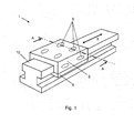
FIG. 1 is a schematic view that shows the overall configuration of a slide table device according to an embodiment of the invention; -
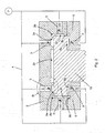
FIG. 2 is a sectional view taken along the line A-A inFIG. 1 ; -
FIG. 3 is a detailed view of a portion B inFIG. 2 ; -
FIG. 4 is a sectional view taken along the line C-C inFIG. 3 ; and -
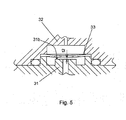
FIG. 5 shows an operation of a variable flow-rate adjusting portion. - Hereinafter, embodiments of the invention will be described with reference to the accompanying drawings.
- As shown in
FIG. 1 , in a table feeding device 1, a table 2 (bearing body) is slidably mounted on a slide portion of a base 10 (fixed member), and a pair of holding plates 5 (bearing body) is connected to the lower portions of respective ends of the table 2. Thus, the table 2 is movable only in an X-axis direction. - As shown in
FIG. 2 , the table 2 has, in its surfaces that face thebase 10, twopockets 2a that open downward and a pair ofpockets 2c that face each other in the lateral direction. Two-stage flow-rate adjusters 3 are communicated with therespective pockets rate adjuster 3 is formed by arranging fixed orifices and a variable flow-rate adjusting portion in series.Oil supply ducts 4 are communicated with the respective two-stage flow-rate adjusters 3. Adrain groove 2b is formed around eachpocket 2a. - Each
holding plate 5 has apocket 5a that opens upward. Two-stage flow-rate adjusters 3 are communicated with therespective pockets 5a.Oil supply ducts 4 are communicated with the respective two-stage flow-rate adjusters 3. Adrain groove 5b is formed around eachpocket 5a. -
FIG. 3 shows the details of each two-stage flow-rate adjuster 3. Each two-stage flow-rate adjuster 3 has a structure in which a variable flow-rate adjustingbase 31 that has afluid storage chamber 31a and acap 32 that has afluid supply chamber 32a are fastened together with abolt 35, at amating surface 3a such that thefluid storage chamber 31a and thefluid supply chamber 32a are aligned with each other, and an O-ring 34 is provided at an assembled portion. The variable flow-rate adjustingbase 31 has aprojection 31b and adischarge port 31c at the center portion of thefluid storage chamber 31a. Anouter periphery 31d of thefluid storage chamber 31a is circular. A leaf spring fixedportion 31e that is parallel to the upper face of theprojection 31b is formed around theouter periphery 31d. Aleaf spring 33 is fitted onto the upper face of the leaf spring fixedportion 31e, and is fixed between the leaf spring fixedportion 31e and thecap 32. - The upper face of the leaf spring fixed
portion 31e and the upper face of theprojection 31b are set such that a predetermined level difference t1 is formed therebetween. When theleaf spring 33 is not deflected, the upper face of theprojection 31b faces theleaf spring 33 with a clearance t1 left therebetween. Theleaf spring 33 hasfixed orifices 33a that provide communication between thefluid supply chamber 32a and thefluid storage chamber 31a. As shown inFIG. 4 , thefixed orifices 33a are arranged at four positions that are rotationally symmetric with respect to the center of theouter periphery 31d. Theduct 4 is communicated with thefluid supply chamber 32a via aflow passage 32b, and thedischarge port 31c is communicated with thepocket 2a via aninflow passage 2d of the table 2. - An operation of the variable flow-rate hydrostatic bearing will be described with reference to
FIG. 3 andFIG. 5 . When a fluid is supplied to theduct 4, thefluid supply chamber 32a is filled with fluid, thefluid storage chamber 31a is filled with fluid via thefixed orifices 33a, and, furthermore, the fluid in thefluid storage chamber 31a flows at a flow rate Q into thepocket 2a via a clearance between theleaf spring 33 and theprojection 31b and thedischarge port 31c. The fluid flows at the flow rate Q from thepocket 2a into thedrain groove 2b via a clearance t3 between thepocket 2a and thebase 10. - The above-described operation also occurs at each of the
pockets 2c formed in the table 2 so as to extend vertically and at thepockets 5a of theholding plates 5. As a result, thebase 10 and the table 2 are held with the clearance t3 left therebetween at eachpocket 2a portion. - At this time, when the pressure of fluid supplied to the
fluid supply chamber 32a is P0, the pressure inside thefluid storage chamber 31a is to P1 that is lower than P0 because the pressure of the fluid is reduced by thefixed orifices 33a. The pressure inside thepocket 2a is P2 that is lower than P1 because the pressure of the fluid is further reduced at the clearance between theleaf spring 33 and theprojection 31b. Therefore, as shown inFIG. 5 , theleaf spring 33 receives force due to a pressure difference and is deflected in the direction toward theprojection 31b. The clearance between theleaf spring 33 and theprojection 31b becomes t2 at which a force generated by the pressures P0 and P1 that are applied to respective faces of theleaf spring 33 and the pressure P2 in thepocket 2a, which is applied to thedischarge port 31c, and the elastic restoring force of theleaf spring 33 balance out each other. - When a downward load is applied to the table 2 in this state, the table 2 moves downward. Therefore, the clearance t3 between the
pocket 2a and thebase 10 decreases, and the amount of fluid discharged from the clearance t3 decreases. Then, the pressure inside thepocket 2a increases. Therefore, the pressure in thedischarge port 31c that is in communication with thepocket 2a also increases. - Accordingly, upward force received by the face of the
leaf spring 33, which faces thedischarge port 31c, increases, theleaf spring 33 is deflected upward, and the clearance t2 between theleaf spring 33 and theprojection 31b increases. As a result, the flow rate of the fluid that flows into thepocket 2a via the clearance t2 and thedischarge port 31c increases. As the flow rate of the fluid that is discharged from the clearance t3 between thepocket 2a and thebase 10 increases, an action of reducing changes in the clearance t3 with respect to a load (increasing the stiffness) works. As a result, reduction in the clearance t3 between thepocket 2a and thebase 10 is prevented. - According to the invention, the operation of each variable flow-rate adjusting portion is a motion due to elastic deformation. Therefore, smooth motion is possible and another fixed member does not contact a moving portion.
- When a movable member is used, the sum of the flow rate of the fluid discharged from a fixed orifice formed in the movable member and the flow rate of fluid discharged from the clearance between the movable member and the wall of a guide hole is the fixed orifice flow rate. However, because the flow rate of the fluid discharged from the clearance changes with a change in the position of the movable member, the fixed orifice flow rate changes. In the invention, because there is no flow passage other than the fixed
orifices 33a, the fixed orifice flow rate does not change. - Furthermore, each variable flow-rate adjusting portion adjusts the flow rate by changing the clearance between the
leaf spring 33 and theprojection 31b in accordance with the pressure inside thepocket 2a. Therefore, theleaf spring 33 desirably makes a motion while being in parallel to the upper face of theprojection 31b. Particularly, when theleaf spring 33 is tilted in the case where the flow rate is reduced, part of theleaf spring 33 contacts theprojection 31b, and it is not possible to further reduce the flow rate. In the invention, the fixedorifices 33a of theleaf spring 33 and the fixed portion are rotationally symmetric with respect to theprojection 31b. Therefore, the center portion of theleaf spring 33 is able to make a motion while being in parallel to the flat surface of theprojection 31b. - As described above, according to the invention, it is possible to obtain the variable flow-rate hydrostatic bearing that includes the fixed orifice having a fixed reduction rate and the variable flow-rate adjusting portion that is able to reduce the flow rate to a considerably low flow rate.
- In the above description, the invention is applied to a linear motion table feeding. Alternatively, the invention may be applied to a rotary shaft. The fixed member in this case is the rotary shaft.
A variable flow-rate hydrostatic bearing includes a variable flow-rate adjusting portion that reduces the flow rate of fluid and then introduces the fluid into a pocket. The variable flow-rate adjusting portion is configured such that a fluid supply chamber (32a) is separated from a fluid storage chamber (31a) having a projection (31b) by a leaf spring (33) that faces the projection (31b) with a predetermined clearance left therebetween, and the projection (31b) has an opening (31c) and a flow passage that is in communication with the pocket (2a). In the variable flow-rate hydrostatic bearing, a fixed orifice (33a) that provides communication between the fluid supply chamber (32a) and the fluid storage chamber (31a) is formed in the leaf spring (33) at a portion that does not face the projection (31b).
Claims (2)
- A variable flow-rate hydrostatic bearing, comprising:a bearing body that is arranged with a clearance left between the bearing body and a fixed member;a pocket that is formed in the bearing body so as to face the fixed member;a fluid supply port through which fluid is supplied to the pocket; anda variable flow-rate adjusting portion that reduces a flow rate of the fluid that is supplied from the fluid supply port and then introduces the fluid into the pocket,wherein the variable flow-rate adjusting portion includes:a fluid supply chamber;a fluid storage chamber that has a projection at a center portion;a leaf spring that separates the fluid supply chamber from the fluid storage chamber, an outer peripheral portion of the leaf spring being fixed, and a surface of the leaf spring, which is perpendicular to a thickness direction of the leaf spring, facing the projection with a predetermined clearance left between the leaf spring and the projection; anda flow passage that is formed in the projection so as to be communicated with the pocket, andwherein a fixed orifice that provides communication between the fluid supply chamber and the fluid storage chamber is formed in the leaf spring at a portion that does not face the projection.
- The variable flow-rate hydrostatic bearing according to claim 1, wherein
an inner periphery of a fixed portion for the leaf spring is in a circular shape, and a plurality of the fixed orifices is formed so as to be rotationally symmetric with respect to the center of the circular shape.
Applications Claiming Priority (1)
| Application Number | Priority Date | Filing Date | Title |
|---|---|---|---|
| JP2011237387A JP2013096445A (en) | 2011-10-28 | 2011-10-28 | Variable throttle type static-pressure bearing |
Publications (1)
| Publication Number | Publication Date |
|---|---|
| EP2587080A1 true EP2587080A1 (en) | 2013-05-01 |
Family
ID=47172352
Family Applications (1)
| Application Number | Title | Priority Date | Filing Date |
|---|---|---|---|
| EP12189383.8A Withdrawn EP2587080A1 (en) | 2011-10-28 | 2012-10-22 | Variable flow-rate hydrostatic bearing |
Country Status (4)
| Country | Link |
|---|---|
| US (1) | US20130108192A1 (en) |
| EP (1) | EP2587080A1 (en) |
| JP (1) | JP2013096445A (en) |
| CN (1) | CN103089813A (en) |
Cited By (6)
| Publication number | Priority date | Publication date | Assignee | Title |
|---|---|---|---|---|
| CN103846751A (en) * | 2012-12-04 | 2014-06-11 | 株式会社捷太格特 | Hydrostatic guide device and machine tool using the hydrostatic guide device |
| CN105443578A (en) * | 2015-12-27 | 2016-03-30 | 天津尚吉液压设备有限公司 | Single-degree-of-freedom T-shaped hydraulic bearing |
| CN105443577A (en) * | 2015-12-27 | 2016-03-30 | 天津尚吉液压设备有限公司 | Two-degree-of-freedom T-shaped hydraulic bearing |
| CZ307730B6 (en) * | 2017-01-23 | 2019-04-03 | Vysoká Škola Báňská-Technická Univerzita Ostrava | Sliding bearing with regulating element |
| EP3647614A1 (en) * | 2018-10-29 | 2020-05-06 | Otto Bihler Handels-Beteiligungs-GmbH | Linear feed device and object processing device provided therewith |
| EP3954497A1 (en) * | 2020-08-11 | 2022-02-16 | Patrick Meunier | High accuracy sliding assembly for a manufacturing machine, and manufacturing machine comprising at least one such assembly |
Families Citing this family (12)
| Publication number | Priority date | Publication date | Assignee | Title |
|---|---|---|---|---|
| JP6221349B2 (en) * | 2013-05-28 | 2017-11-01 | 株式会社ジェイテクト | Variable throttle hydrostatic bearing |
| CN104500569A (en) * | 2014-12-23 | 2015-04-08 | 天津尚吉液压设备有限公司 | T-shaped hydraulic bearing of single restraint DOF |
| JP6476910B2 (en) * | 2015-01-23 | 2019-03-06 | 株式会社ジェイテクト | Hydrostatic bearing device, spindle device for machine tool using hydrostatic bearing device, and manufacturing method of hydrostatic bearing device |
| TWI662203B (en) * | 2015-07-15 | 2019-06-11 | 國立清華大學 | Hydraulic compact bearing system and machine stage system equipping the same |
| CN106763190B (en) * | 2017-02-16 | 2018-12-11 | 西安建筑科技大学 | A kind of intelligent dynamic and hydrostatic bearing based on negative poisson's ratio structure |
| TWI641768B (en) * | 2017-06-09 | 2018-11-21 | 國立清華大學 | Film restrictor and hydrostatic bearing module |
| CN111288083A (en) * | 2018-12-06 | 2020-06-16 | 财团法人工业技术研究院 | Hydrostatic bearing assembly |
| JP7234808B2 (en) * | 2019-06-05 | 2023-03-08 | 株式会社ジェイテクト | Machine tools with hydrostatic fluid support |
| CN115351562B (en) * | 2022-10-21 | 2023-04-07 | 中国机械总院集团海西(福建)分院有限公司 | Hydrostatic pressure spindle unit and lathe applied to lathe |
| CN115351561B (en) * | 2022-10-21 | 2023-04-07 | 中国机械总院集团海西(福建)分院有限公司 | Hydrostatic pressure guide rail assembly applied to machine tool and machine tool |
| CN115351595B (en) * | 2022-10-21 | 2023-04-07 | 中国机械总院集团海西(福建)分院有限公司 | Feedback throttling device and machine tool applied to machine tools |
| DE102023103853B3 (en) | 2023-02-16 | 2024-03-21 | Hiwin Technologies Corp. | MEMBRANE-TYPE FLOW LIMITER AND HYDROSTATIC DEVICE COMPRISING THIS FLOW LIMITER |
Citations (4)
| Publication number | Priority date | Publication date | Assignee | Title |
|---|---|---|---|---|
| US3110527A (en) * | 1959-10-29 | 1963-11-12 | Gen Electric | Hydrostatic bearing |
| US3603652A (en) * | 1969-03-05 | 1971-09-07 | Heald Machine Co | Slide bearings for machine tool way |
| JP2002286037A (en) | 2001-03-27 | 2002-10-03 | Foundation For Advancement Of Science & Technology | Variable throttle type hydrostatic bearing |
| JP2011043232A (en) * | 2009-08-24 | 2011-03-03 | Tokyo Univ Of Science | Hydrostatic bearing and pressure control unit thereof |
Family Cites Families (2)
| Publication number | Priority date | Publication date | Assignee | Title |
|---|---|---|---|---|
| US3661060A (en) * | 1970-08-05 | 1972-05-09 | Duriron Co | Diaphragms for high pressure compressors and pumps |
| BE779833A (en) * | 1971-03-29 | 1972-06-16 | Rech De La Centre D Etudes | FLUID FILM SUSTENTATION DEVICE |
-
2011
- 2011-10-28 JP JP2011237387A patent/JP2013096445A/en not_active Withdrawn
-
2012
- 2012-10-10 CN CN2012103822225A patent/CN103089813A/en active Pending
- 2012-10-17 US US13/653,686 patent/US20130108192A1/en not_active Abandoned
- 2012-10-22 EP EP12189383.8A patent/EP2587080A1/en not_active Withdrawn
Patent Citations (4)
| Publication number | Priority date | Publication date | Assignee | Title |
|---|---|---|---|---|
| US3110527A (en) * | 1959-10-29 | 1963-11-12 | Gen Electric | Hydrostatic bearing |
| US3603652A (en) * | 1969-03-05 | 1971-09-07 | Heald Machine Co | Slide bearings for machine tool way |
| JP2002286037A (en) | 2001-03-27 | 2002-10-03 | Foundation For Advancement Of Science & Technology | Variable throttle type hydrostatic bearing |
| JP2011043232A (en) * | 2009-08-24 | 2011-03-03 | Tokyo Univ Of Science | Hydrostatic bearing and pressure control unit thereof |
Cited By (6)
| Publication number | Priority date | Publication date | Assignee | Title |
|---|---|---|---|---|
| CN103846751A (en) * | 2012-12-04 | 2014-06-11 | 株式会社捷太格特 | Hydrostatic guide device and machine tool using the hydrostatic guide device |
| CN105443578A (en) * | 2015-12-27 | 2016-03-30 | 天津尚吉液压设备有限公司 | Single-degree-of-freedom T-shaped hydraulic bearing |
| CN105443577A (en) * | 2015-12-27 | 2016-03-30 | 天津尚吉液压设备有限公司 | Two-degree-of-freedom T-shaped hydraulic bearing |
| CZ307730B6 (en) * | 2017-01-23 | 2019-04-03 | Vysoká Škola Báňská-Technická Univerzita Ostrava | Sliding bearing with regulating element |
| EP3647614A1 (en) * | 2018-10-29 | 2020-05-06 | Otto Bihler Handels-Beteiligungs-GmbH | Linear feed device and object processing device provided therewith |
| EP3954497A1 (en) * | 2020-08-11 | 2022-02-16 | Patrick Meunier | High accuracy sliding assembly for a manufacturing machine, and manufacturing machine comprising at least one such assembly |
Also Published As
| Publication number | Publication date |
|---|---|
| CN103089813A (en) | 2013-05-08 |
| JP2013096445A (en) | 2013-05-20 |
| US20130108192A1 (en) | 2013-05-02 |
Similar Documents
| Publication | Publication Date | Title |
|---|---|---|
| US20130108192A1 (en) | Variable flow-rate hydrostatic bearing | |
| EP3187730B1 (en) | Variable-capacity compressor control valve | |
| EP2251556B1 (en) | Self-compensating hydrostatic planar bearing device and the method thereof | |
| EP2573406A1 (en) | Pressure control valve | |
| CA2868042C (en) | Fluid regulator having improved flow stability | |
| JP2013087875A (en) | Variable throttle type hydrostatic bearing | |
| JP6394370B2 (en) | Variable throttle hydrostatic bearing | |
| JP6395696B2 (en) | Control valve for variable displacement compressor | |
| JP5040826B2 (en) | Valve device | |
| JP5582342B2 (en) | Vehicle oil supply device | |
| CN103080549A (en) | Arrangement for throttling a fluid flow, and corresponding piston pump for delivering fluids | |
| US20170114682A1 (en) | Relief device of oil circuit of engine | |
| US10054161B1 (en) | Membrane restrictor and hydrostatic bearing module | |
| JP5327801B2 (en) | Hydrostatic bearing | |
| JP2017172598A (en) | Pump device | |
| JP2016061276A (en) | Variable capacity type vane pump | |
| JP6160371B2 (en) | Variable throttle hydrostatic bearing | |
| JP5831170B2 (en) | Variable throttle hydrostatic bearing | |
| KR101635384B1 (en) | Hybrid Linear Motion guide | |
| CN111336290B (en) | Safety valve | |
| CN211259719U (en) | Back pressure valve | |
| JP6638222B2 (en) | Flow control device | |
| JP4805711B2 (en) | Valve device and pressure regulator equipped with the same | |
| JP4629256B2 (en) | Variable throttle hydrostatic bearing | |
| JP5406359B1 (en) | Fluid flow regulator |
Legal Events
| Date | Code | Title | Description |
|---|---|---|---|
| PUAI | Public reference made under article 153(3) epc to a published international application that has entered the european phase |
Free format text: ORIGINAL CODE: 0009012 |
|
| AK | Designated contracting states |
Kind code of ref document: A1 Designated state(s): AL AT BE BG CH CY CZ DE DK EE ES FI FR GB GR HR HU IE IS IT LI LT LU LV MC MK MT NL NO PL PT RO RS SE SI SK SM TR |
|
| AX | Request for extension of the european patent |
Extension state: BA ME |
|
| STAA | Information on the status of an ep patent application or granted ep patent |
Free format text: STATUS: THE APPLICATION IS DEEMED TO BE WITHDRAWN |
|
| 18D | Application deemed to be withdrawn |
Effective date: 20131105 |