EP2587038A1 - Variable width gap seal - Google Patents
Variable width gap seal Download PDFInfo
- Publication number
- EP2587038A1 EP2587038A1 EP12189802.7A EP12189802A EP2587038A1 EP 2587038 A1 EP2587038 A1 EP 2587038A1 EP 12189802 A EP12189802 A EP 12189802A EP 2587038 A1 EP2587038 A1 EP 2587038A1
- Authority
- EP
- European Patent Office
- Prior art keywords
- fitting
- seal
- sheet
- trailing edge
- aircraft exhaust
- Prior art date
- Legal status (The legal status is an assumption and is not a legal conclusion. Google has not performed a legal analysis and makes no representation as to the accuracy of the status listed.)
- Granted
Links
Images

Classifications
-
- F—MECHANICAL ENGINEERING; LIGHTING; HEATING; WEAPONS; BLASTING
- F16—ENGINEERING ELEMENTS AND UNITS; GENERAL MEASURES FOR PRODUCING AND MAINTAINING EFFECTIVE FUNCTIONING OF MACHINES OR INSTALLATIONS; THERMAL INSULATION IN GENERAL
- F16J—PISTONS; CYLINDERS; SEALINGS
- F16J15/00—Sealings
- F16J15/02—Sealings between relatively-stationary surfaces
- F16J15/06—Sealings between relatively-stationary surfaces with solid packing compressed between sealing surfaces
- F16J15/10—Sealings between relatively-stationary surfaces with solid packing compressed between sealing surfaces with non-metallic packing
- F16J15/104—Sealings between relatively-stationary surfaces with solid packing compressed between sealing surfaces with non-metallic packing characterised by structure
-
- F—MECHANICAL ENGINEERING; LIGHTING; HEATING; WEAPONS; BLASTING
- F02—COMBUSTION ENGINES; HOT-GAS OR COMBUSTION-PRODUCT ENGINE PLANTS
- F02K—JET-PROPULSION PLANTS
- F02K1/00—Plants characterised by the form or arrangement of the jet pipe or nozzle; Jet pipes or nozzles peculiar thereto
- F02K1/78—Other construction of jet pipes
- F02K1/80—Couplings or connections
- F02K1/805—Sealing devices therefor, e.g. for movable parts of jet pipes or nozzle flaps
-
- F—MECHANICAL ENGINEERING; LIGHTING; HEATING; WEAPONS; BLASTING
- F16—ENGINEERING ELEMENTS AND UNITS; GENERAL MEASURES FOR PRODUCING AND MAINTAINING EFFECTIVE FUNCTIONING OF MACHINES OR INSTALLATIONS; THERMAL INSULATION IN GENERAL
- F16J—PISTONS; CYLINDERS; SEALINGS
- F16J15/00—Sealings
- F16J15/02—Sealings between relatively-stationary surfaces
- F16J15/06—Sealings between relatively-stationary surfaces with solid packing compressed between sealing surfaces
- F16J15/08—Sealings between relatively-stationary surfaces with solid packing compressed between sealing surfaces with exclusively metal packing
- F16J15/0887—Sealings between relatively-stationary surfaces with solid packing compressed between sealing surfaces with exclusively metal packing the sealing effect being obtained by elastic deformation of the packing
-
- Y—GENERAL TAGGING OF NEW TECHNOLOGICAL DEVELOPMENTS; GENERAL TAGGING OF CROSS-SECTIONAL TECHNOLOGIES SPANNING OVER SEVERAL SECTIONS OF THE IPC; TECHNICAL SUBJECTS COVERED BY FORMER USPC CROSS-REFERENCE ART COLLECTIONS [XRACs] AND DIGESTS
- Y02—TECHNOLOGIES OR APPLICATIONS FOR MITIGATION OR ADAPTATION AGAINST CLIMATE CHANGE
- Y02T—CLIMATE CHANGE MITIGATION TECHNOLOGIES RELATED TO TRANSPORTATION
- Y02T50/00—Aeronautics or air transport
- Y02T50/60—Efficient propulsion technologies, e.g. for aircraft
Definitions
- This disclosure relates generally to seals, and more specifically to seals for accommodating an interface having a variable width.
- Aircraft typically include exhaust systems for directing exhaust gases from one or more engines to the ambient air.
- the aviation industry historically used exhaust systems that were round in shape. These round exhaust systems were highly reflective and therefore, easily detected by radar.
- Some modem aircraft now use “non-round” exhaust systems with “reduced signature features” to better avoid detection by radar.
- seals are commonly employed between components for various purposes.
- Known seals for exhaust systems include M-seals, rope seals, and finger seals. Seal type and specific structure is chosen based on its desired properties and application. Often seals are designed to prevent or accurately control air leakage between components. The extent to which a given seal accomplishes its purpose, otherwise known as “sealing efficiency", can affect overall aircraft performance.
- a seal for bridging an interface between an aircraft exhaust deck and a trailing edge of an aircraft exhaust system includes a sheet, a spacing element, and a tensioning element.
- the sheet has a fixed end, a cover portion, a movable portion, and a free end.
- the fixed end is anchored to the trailing edge.
- the cover portion extends upstream from the fixed end and across the interface.
- the movable portion is located adjacent the aircraft exhaust deck.
- the spacing element engages the movable portion and defines a gap for cooling air between the movable portion and the aircraft exhaust deck.
- the tensioning element is attached to the free end and provides tensioning force keep the cover portion taut.
- a seal for bridging an interface between a first material and a second material includes a first fitting, a second fitting, a sheet, a spacing element, and a tensioning element.
- the first fitting has a top and a downstream side. The downstream side interacts with the first material on a first side of the interface.
- the second fitting has a top and an upstream side. The upstream side interacts with the second material on a second side of the interface.
- the sheet has a fixed end, a cover portion, a movable portion, and a free end. The fixed end is anchored between the downstream side of the first fitting and the first material.
- the cover portion extends upstream from the fixed end and across the tops of both the first fitting and the second fitting to bridge the interface.
- the movable portion extends along the upstream side of second fitting.
- the spacing element engages the movable portion and defines a gap for cooling air between the movable portion and the second material.
- the tensioning element is attached to the free end and provides tensioning force to keep the cover portion taut.
- a seal for bridging an interface between a first material and a second material includes a first fitting, a second fitting, an expansion element, a sheet, a spacing element, and a tensioning element.
- the first fitting has a top and a downstream side that interacts with the first material on a first side of the interface.
- the second fitting has a support and a tube.
- the tube has a rotating engagement with a concave side of the support and an interaction with the second material on a second side of the interface.
- the expansion element is located between the first fitting and the second fitting. The expansion element exerts an expansion force against both the first fitting and second fitting to accommodate changes in interface size.
- the sheet has a fixed end, a cover portion, a movable portion, and a free end.
- the fixed end is anchored between the downstream side of the first fitting and the first material.
- the cover portion extends upstream from the fixed end across the tops of both the first fitting and the second fitting to bridge the interface.
- the movable portion extends along the upstream side of second fitting.
- the spacing element engages the movable portion of the sheet and defines a gap for cooling air between the movable portion and the second material.
- the tensioning element is attached to the free end and provides tensioning force to keep the cover portion taut.
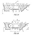
- FIG. 1A is an exploded cross-sectional view of a variable width seal between two materials in accordance with the present disclosure.
- FIG. 1B is an assembled cross-sectional view of the variable width seal of FIG. 1A .
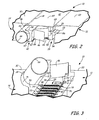
- FIG. 2 is a cut-away top perspective view of the variable width seal of FIGS. 1A and 1B .
- FIG. 3 is a cut-away bottom perspective view of the variable width seal of FIGS. 1A-2 .
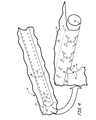
- FIG. 4 is an exploded and rotated view of an aircraft exhaust deck, a sheet, and a reel tube from the variable width seal of FIGS. 1A - 3 .
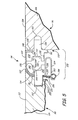
- FIG. 5 is a cross-sectional view of another embodiment of a variable width seal in accordance with the present disclosure.
- FIG. 6 is a cross-sectional view of another embodiment of a variable width seal in accordance with the present disclosure.
- FIG. 1A is an exploded cross-sectional view and FIG. 1B is an assembled cross-sectional view of variable width seal 10 between trailing edge 12 and aircraft exhaust deck 14 of an aircraft exhaust system.
- Seal 10 spans interface 16 between trailing edge 12 and aircraft exhaust deck 14, and also accommodates gap 18 for cooling air.
- Trailing edge 12 includes top 20, downstream side 24, upstream side 26, and notch 28.
- Aircraft exhaust deck includes top 30, upstream side 34, and downstream side 36.
- Seal 10 includes trailing edge (TE) fitting 38, aircraft exhaust deck (AD) fitting 40, sheet 42, tensioning elements 44, and expansion element 46.
- TE fitting 38 includes top 48, bottom 50, upstream side 52, and downstream side 54, and tang 56.
- AD fitting 40 includes top 58, bottom 60, downstream side 62, upstream side 64, and reel tube 66. Seal 10 is configured to expand and contract in order to accommodate changes in width of interface 16.
- Trailing edge 12 has top 20, downstream side 24, and upstream side 26.
- Top 20 is an uppermost portion of trailing edge 12 and is in contact with a flow of hot gases HG.
- downstream side 24 of trailing edge 12 is downstream of upstream side 26.
- Notch 28 is formed centrally in upstream side 26 of trailing edge 12.
- Aircraft exhaust deck 14 has top 30, upstream side 34, and downstream side 36.
- Top 30 is an uppermost portion of aircraft exhaust deck 14 and is in contact with a flow of hot gases HG.
- upstream side 34 of aircraft exhaust deck is upstream of downstream side 36.
- the space between upstream side 26 of trailing edge 12 and downstream side 36 of aircraft exhaust deck 14 forms interface 16.
- Trailing edge 12 and aircraft exhaust deck 14 are joined at interface 16 to form a portion of an aircraft exhaust system.
- Aircraft exhaust deck 14 is located upstream of trailing edge 12.
- Hot gases HG from an aircraft engine flow across top 30 of aircraft exhaust deck 14 and subsequently, across top 20 of trailing edge 12.
- Trailing edge 12 is the most terminal portion of the exhaust system and therefore, downstream side 24 can be adjacent a flow of ambient air AA. Accordingly, a large temperature gradient (about 1000 degrees Fahrenheit) may exist across trailing edge 12.
- a flow of cooling air CA e.g. pressurized bleed air from compressor of engine
- trailing edge 12 is formed from a ceramic matrix composite while aircraft exhaust deck 14 is formed from a metal. Since the metal of aircraft exhaust deck 14 will exhibit five to six times more thermal growth than the ceramic composite of trailing edge 12, interface 16 width will vary. Seal 10 is designed to accommodate this variance of interface 16 while maintaining a consistent size gap 18 for cooling air CA.
- Seal 10 includes TE fitting 38 at a downstream side and AD fitting 40 at an upstream side.
- Sheet 42 extends across tops of both TE fitting 38 and AD fitting 40 to bridge interface 16.
- sheet 42 is formed from metal.
- a plurality of tensioning elements 44 extend between sheet 42 and TE fitting 38. Each tensioning element 44 has a first or upstream side attached to sheet 42 and a second or downstream side attached to TE fitting 38.
- tensioning elements 44 are metal helical tension springs for exerting a tensioning force on sheet 42.
- Expansion element 46 is centrally located between TE fitting 38 and AD fitting 40.
- expansion element 46 is a single corrugated metal spring that exerts an expansion force against both TE fitting 38 and AD fitting 40.
- expansion element 46 includes an outward bias for engaging TE fitting 38 and AD fitting 40.
- expansion element 46 is in a partially compressed form so that it can expand or contract to vary an overall width of seal 10 in response to a changed in interface 16 size.
- TE fitting 38 is defined by top 48, bottom 50, upstream side 52, and downstream side 54. As indicated by name, top 48 is above bottom 50 and upstream side 52 is located upstream of downstream side 54. Downstream side 54 of TE fitting includes tang 56 extending in a downstream direction toward trailing edge 12. Tang 56 is received into notch 28 located in upstream side 26 of trailing edge 12. A downstream or fixed end of sheet 42 is located between upstream side 26 of trailing edge 12 and downstream side 54 of TE fitting 38. A central or cover portion of sheet 42 extends in an upstream direction along top 48 of TE fitting 38.
- AD fitting 40 is defined by top 58, bottom 60, downstream side 62, and upstream side 64. As indicated by name, top 58 is above bottom 60 and downstream side 62 is located downstream of upstream side 64. Reel tube 66 is located between upstream side 64 of AD fitting 40 and downstream side 36 of aircraft exhaust deck 14. Reel tube 66 has a rotating engagement with upstream side of AD fitting 40. Top 58 and bottom 60 have fingers that extend in an upstream direction to engage reel tube 66. The central portion of sheet 42 extends upstream along top 58 of AD fitting 40 and a movable portion of sheet 42 extends along reel tube 66. The movable portion of sheet 42 terminates in a free end that is secured to tensioning elements 44.
- seal 10 is positioned within interface 16 such that TE fitting 38 is facing trailing edge 12, and AD fitting 40/reel 66 are facing aircraft exhaust deck 14.
- Tang 56 of TE fitting 38 inserts into notch 28 of trailing edge 12 to control a vertical location of seal 10.
- Notch 28 can include a generous radius to avoid stress concentration within trailing edge 12.
- downstream side 54 of TE fitting 38 is adjacent upstream side 26 of trailing edge 12.
- Top 48 of TE fitting 38 is aligned with top 20 of trailing edge 12, such that sheet 42 extending across top 48 of TE fitting 38 is flush with top 20 of trailing edge 12.
- Top 58 of AD fitting 40 and reel tube 66 are aligned with top 30 of aircraft exhaust deck 14, such that sheet 42 extending across top 58 of AD fitting and reel tube 66 is flush with top 30 of aircraft exhaust deck 14.
- Downstream side 36 of aircraft exhaust deck 14 cooperates with reel tube 66 and sheet 42 extending around reel tube 66 via spacing elements (shown and described with reference to FIG. 4 ) to define gap 18 for cooling air CA.
- expansion element 46 expands outwardly thereby urging TE fitting 38 toward trailing edge 12 and AD fitting 40/reel 66 toward aircraft exhaust deck 14.
- the increased distance between TE fitting 38 and AD fitting 40 will cause the movable portion of sheet 42 to slide along reel tube 60, similar to the action of a window shade unrolling.
- expansion element 46 is compressed by the movement of TE fitting 38 and AD fitting 40 toward one another.
- Tensioning elements 44 exert tension on the free end of sheet 42 to keep the cover portion taut against top 48 of TE fitting 38 and top 58 of AD fitting, similar to the action of a window shade rolling in.
- sheet 42 is rigid in plane, but flexible to bend.
- gap 18 for cooling air between seal 10 and aircraft exhaust deck 14 remains constant. Spacing elements (shown and described with reference to FIG. 4 ) allow seal 10 to tightly control gap 18 for cooling air while expanding and contracting to bridge varying widths of interface 16. The structure and function of seal 10 is described further below with reference to FIGS. 2 - 4 .
- FIG. 2 is a cut-away top perspective view
- FIG. 3 is a cut-away bottom perspective view, of variable width seal 10 of FIGS. 1A and 1B .
- Seal 10 is located within interface 16 between trailing edge 12 and aircraft exhaust deck 14 and accommodates gap 18.
- Seal 10 includes TE fitting 38, AD fitting 40, sheet 42, tensioning elements 44, and expansion element 46.
- TE fitting 38 includes top 48, bottom 50, upstream side 52, and downstream side 54, and tang 56.
- AD fitting 40 includes top 58, bottom 60, downstream side 62, upstream side 64, and reel tube 66.
- Sheet 42 includes downstream or fixed end 68, central or cover portion 69, free or upstream end 70, movable portion 71, bead 72, and holes 74.
- Each tension element 44 includes first or downstream end 78, second or upstream end 80, and coiled center 82.
- Expansion element 46 includes first side 84, second side 86, and folds 88.
- Tensioning elements 44 exert a tensioning force on sheet 42 while expansion element 46 exerts an expansion force on TE fitting 38 and AD fitting 40, such that seal 10 can accommodate variable width interface 16.
- TE fitting 38 cooperates with trailing edge 12, and AD fitting 40/reel tube 66 cooperate with aircraft exhaust deck 14.
- Sheet 42 extends across both TE fitting 38 and AD fitting 40, and subsequently around reel tube 66. More specifically, downstream or fixed end 68 of sheet 42 is anchored between downstream side 54 of TE fitting 38 and upstream side 26 of trailing edge 12. From downstream end 68, cover portion 69 of sheet 42 extends in the upstream direction across top 48 of TE fitting 38, over expansion element 46, and across top 58 of AD fitting 40. Movable portion 71 extends from cover portion 69 and wraps around reel tube 66 toward bottom 60 of AD fitting 40.
- Upstream or free end 70 of sheet 42 is located adjacent bottom 60 of AD fitting and includes bead 72, which can be a folded (e.g. doubled back) and/or reinforced section of sheet 42.
- Upstream side 64 of AD fitting 40 is concave to receive reel tube 66 and allow reel tube 66 to rotate.
- An upstream side of both top 58 and bottom 60 and AD fitting 40 include projections to contain reel tube 66.
- Movable portion 71 of sheet 42 is movable such that it slides or scrolls along reel tube 66 to accommodate changes in an overall width of seal 10.
- a series of holes 74 extend through bead 72 for receiving tensioning elements 44.
- a series of holes 76 are formed in bottom 50 of TE fitting 38 for receiving tensioning elements 44.
- Each hole 76 is directly downstream of one of holes 74.
- tensioning elements 44 are metal coiled springs.
- Each tensioning element 44 has first end 78, second end 80, and coiled center 82 extending between first end 78 and second end 80.
- First end 78 has a hook that extends through hole 76 to couple tensioning element 44 to TE fitting 38.
- second end 80 has a hook that extends through hole 74 to couple tensioning element 44 to upstream end 70 of sheet 42. Accordingly, a series of tensioning elements 44 are attached between TE fitting 38 and sheet 42 to keep sheet 42 taut regardless of an overall width of seal 10.
- expansion element 46 is a metal corrugated spring having an outward bias for engaging TE fitting 38 and AD fitting 40.
- Expansion element 46 has first side 84 in contact with upstream side 52 of TE fitting 38, which forms a track for receiving first side 84 of expansion element 46.
- second side 86 of expansion element 46 is in contact with downstream side 62 of AD fitting 40, which forms a track for receiving second side 86 of expansion element 46.
- Vertical folds 88 are alternately located on first side 84 and second side 86 of expansion element 46.
- Expansion element 46 exerts an expansion force against both TE fitting 38 and AD fitting 40 to increase an overall width of seal 10 in response to growth in width of interface 16.
- the force of expansion element 46 is greater than the force of tensioning element 44 and therefore, seal 10 remains contained within interface 16.
- FIG. 4 is an exploded and rotated view of aircraft exhaust deck 14, sheet 42, and reel tube 66 from variable width seal 10 of FIGS. 1A - 3 .
- Aircraft exhaust deck 14 includes top 30, downstream side 36, and spacing elements 90.
- Sheet 42 includes cover portion 69, movable portion 71 and slots 92. Spacing elements 90 of aircraft exhaust deck 14 cooperate with slots 92 in sheet 42 to define gap 18 for cooling air CA.
- gap 18 for cooling air CA is located between seal 10 and aircraft exhaust deck 14. More specifically, cooling air CA flows upwardly along downstream side 36 of aircraft exhaust deck and upstream end 70 of sheet 42. Spacing elements 90 define and maintain a constant space for gap 18. In the depicted embodiment, spacing elements 90 are stand off feet that protrude in a downstream direction from the concave surface of downstream side 36 of aircraft exhaust deck 14. In the depicted embodiment, two rows of spacing elements 90 are positioned in parallel along downstream side 36 of aircraft exhaust deck 14. A first row of spacing elements 90 is positioned near top 30 and a second row is positioned beneath the first row. To cooperate with spacing elements 90, movable portion 70 of sheet 42 includes a plurality of slots 92.
- spacing elements 90 Like spacing elements 90, two parallel rows of slots 92 extend through movable portion 70 of sheet. Both spacing elements 90 and slots 92 are ellipse shaped. Slots 92, however, are larger than spacing elements 90 and therefore allow for movement of sheet 42 around spacing elements 90.
- each slot 92 in movable portion 70 of sheet 92 receives a spacing element 90 extending from downstream side 36 of aircraft exhaust deck 14.
- the cooperation between slots 92 and spacing elements 90 keeps seal 10 securely positioned within interface 16, while tightly controlling the space for gap 18.
- gap 18 has a width of about 0.005 inches (0.1 mm) and sheet 42 has a thickness of about 0.005 inches (0.1 mm).
- movable portion 71 of sheet 42 moves or scrolls along reel 66.
- Each spacing element 90 is configured to slide from one side of a given slot 92 to a second, opposite side of the given slot 92 to accommodate this movement of sheet 42. Cooling air CA flows between and around the mating of spacing elements 90 and slots 92 through tightly controlled gap 18 to manage the thermal gradient across trailing edge 12.
- FIG. 5 is a cross-sectional view of another embodiment of variable width seal 94 inserted between trailing edge 96 and aircraft exhaust deck 98 of an aircraft exhaust system.
- Seal 94 spans interface 100 between trailing edge 96 and aircraft exhaust deck 98, and also accommodates gap 102 for cooling air.
- Trailing edge 96 includes top 104, downstream side 106, upstream side 108, and notch 110.
- Aircraft exhaust deck 98 includes top 112, downstream side 114, and upstream side 116.
- Seal 94 includes trailing edge (TE) fitting 118, aircraft exhaust deck (AD) fitting 120, sheet 122, tensioning elements 124, and expansion element 126.
- TE fitting 118 includes top 128, bottom 130, upstream side 132, and downstream side 134, and tang 136.
- AD fitting 120 includes top 140, bottom 142, downstream side 144, and upstream side 146.
- Sheet 122 includes downstream end 148, cover portion 150, movable portion 151, upstream end 152, slots 153, bead 154, and holes 156.
- Each tensioning element 124 includes first end 158 and second end 160.
- TE fitting 118 has protrusion 161
- aircraft exhaust deck 98 has notch 162
- AD fitting 120 has tangs 164.
- Expansion element 126 has first end 166 and second end 168.
- Seal 94 is configured to expand and contract in order to accommodate changes in width of interface 100.
- seal 94 bridges interface 100 between trailing edge 96 and aircraft exhaust deck 98, but seal 94 does not include any rotating parts (i.e. reel tube 66).
- Seal 94 includes TE fitting 118 at a downstream side and AD fitting 120 at an upstream side.
- Sheet 122 extends across both TE fitting 118 and AD fitting 120 to bridge interface 100.
- a plurality of tensioning elements 124 extend between AD fitting 120 and sheet 122 and exert a tensioning force on sheet 122.
- Expansion element 126 is centrally located between TE fitting 118 and AD fitting 120 and exerts an expansion force on both TE fitting 118 and AD fitting 120.
- TE fitting 118 is defined by top 128, bottom 130, upstream side 132, and downstream side 134. As indicated by name, top 128 is above bottom 130 and upstream side 132 is located upstream of downstream side 134. Downstream side 134 of TE fitting 118 includes tang 136 extending in a downstream direction toward trailing edge 96. Tang 136 is received into notch 110 located in upstream side 108 of trailing edge 96.
- AD fitting 120 is defined by top 140, bottom 142, downstream side 144, and upstream side 146. As indicated by name, top 140 is above bottom 142 and downstream side 144 is located downstream of upstream side 146. Top 128 of TE fitting 118 is aligned with top 140 of trailing edge 96, and top 140 of AD fitting 120 is aligned with top 112 of aircraft exhaust deck 98.
- Sheet 122 extends across TE fitting 118 and AD fitting 120 to bridge interface 100. Downstream or fixed end 148 of sheet 122 is secured between upstream side 108 of trailing edge 96 and downstream side 134 of AD fitting 118. From downstream end 148, center portion 150 of sheet 122 extends in an upstream direction across top 128 of TE fitting 118 and top 144 of AD fitting 120. Movable portion 151 of sheet 122 extends along upstream side 146 of AD fitting 120 and terminates in upstream or free end 152, which is secured to tensioning elements 124. A series of slots 153 extend through movable portion 151 of sheet 122 to accommodate tangs 164.
- Gap 102 for cooling air is located between movable portion 151 of sheet 122 and downstream side 114 of aircraft exhaust deck 114.
- gap 102 has a width of about 0.005 inches (0.1 mm) and sheet 122 has a thickness of about 0.005 inches (0.1 mm).
- Upstream end 152 includes bead 154 having holes 156 for receiving tension elements 124.
- tensioning elements 124 are U-shaped sheet metal finger spring with a retention tang. Each tensioning element 124 has first end 158 anchored to bottom 142 AD fitting 120 by a fastener (i.e. rivet, screw, etc.) and second end 160 attached to upstream end 152 of sheet 122.
- Second end 160 of tensioning elements 124 extend through holes 156 at the location of bead 154, which provides reinforcement to sheet 122. Tensioning elements 124 exert a tensioning force on sheet 122 to keep it taut against top 128 of TE fitting 118 and top 140 of AD fitting 120.
- TE fitting 118 also includes protrusion 161 extending downwardly from bottom 130 at downstream side 134. Protrusion 161 is in contact with upstream side 108 of trailing edge 96 and assists in securing TE fitting 118 to trailing edge 96.
- Aircraft exhaust deck 98 includes notch 162 extending in an upstream direction into upstream side 114. Notch 162 is configured to receive spacing elements or tangs 164, which extend in an upstream direction from upstream side 146 of AD fitting 120. Each tang 164 extends through a given slot 153 in movable portion 151 of sheet 122 (similar to slots 92 shown in FIG. 4 ). Notch 92 and tang 94 mate to define gap 102 for cooling air.
- Upstream side 146 of AD fitting 120 is contoured and smooth to allow movable portion 151 of sheet 122 to freely move up and down in response to downward force from tensioning element 124.
- upstream side 146 is formed from a low friction material (i.e. graphite).
- expansion element 126 is a rolled sheet metal finger spring expansion element. Expansion element 126 has first end 166 located near top 140 of AD fitting 120 and second end 168 located near top 128 of TE fitting 118. If interface 100 grows, expansion element 126 will unroll such that first end 166 pushes AD fitting 120 outwardly and second end 168 pushes TE fitting 118 outwardly. In contrast, if interface 100 shrinks, inward force by TE fitting 118 and AD fitting 120 will cause expansion element 126 to curl inwardly on itself.
- seal 94 can assume variable widths to bridge changes in interface 100 size.
- Expansion element 126 allows seal 94 to shrink and grow in width, tensioning elements 124 maintain sheet 122 taut across TE fitting 118 and AD fitting 120 during changes in seal 94 width, and tang 164 and notch 162 cooperate to tightly control gap 102 for cooling air.
- FIG. 6 is a cross-sectional view of another embodiment of variable width seal 170 inserted between trailing edge 172 and aircraft exhaust deck 174 of an aircraft exhaust system.
- Seal 170 spans interface 176 between trailing edge 172 and aircraft exhaust deck 174, and also accommodates gap 178 for cooling air.
- Trailing edge 172 includes top 180, downstream side 182, and upstream side 184.
- Aircraft exhaust deck 174 includes top 186, downstream side 188, and upstream side 190.
- Seal 170 includes trailing edge (TE) fitting 192, aircraft exhaust deck (AD) fitting 194, sheet 196, and tensioning elements 198.
- TE fitting 192 includes top 200, bottom 201, upstream side 202, and downstream side 204.
- AD fitting 194 includes top 206, bottom 208, downstream side 210, and upstream side 212.
- Sheet 196 includes downstream or fixed end 214, central or cover portion 216, movable portion 217, upstream or free end 218, bead 220, and holes 222.
- Tensioning elements 198 include first end 224 and second end 226. Fastener 228 attaches first end 224 to AD fitting 194.
- Aircraft exhaust deck 174 has spacing element 230 that extends through slot 232 in sheet 196.
- First bolt 234 secures AD fitting 194 to aircraft exhaust deck 174 and second bolt 236 secures TE fitting 192 to trailing edge 172.
- Seal 170 is configured to expand and contract in order to accommodate changes in width of interface 176.
- seal 170 bridges interface 176 between trailing edge 172 and aircraft exhaust deck 174.
- seal 170 is fixed to both trailing edge 173 and aircraft exhaust deck 174 and therefore, does not include any expansion element (i.e. reference number 46 in FIGS. 1A - 4 and reference number 126 in FIG. 5 ).
- Seal 170 includes TE fitting 192 at a downstream side and AD fitting 194 at an upstream side.
- Sheet 196 extends across both TE fitting 192 and AD fitting 194 to bridge interface 176.
- a plurality of tensioning elements 198 extend between AD fitting 194 and sheet 196 and exert a tensioning force on sheet 196.
- TE fitting 192 is defined by top 200, bottom 201, upstream side 202, and downstream side 204. As indicated by name, top 200 is located above bottom 201, and upstream side 202 is located upstream of downstream side 204. TE fitting 192 is substantially rectangular such that top 200 is parallel to bottom 201 and upstream side 202 is parallel to downstream side 204.
- AD fitting 194 is defined by top 206, bottom 208, downstream side 210, and upstream side 212. As indicated by name, top 206 is located above bottom 208, and downstream side 210 is located downstream of upstream side 212. Top 200 of TE fitting 192 is aligned with top 180 of trailing edge 172, and top 206 of AD fitting 194 is aligned with top 186 of aircraft exhaust deck 174.
- Sheet 196 extends across TE fitting 192 and AD fitting 194 to bridge interface 176. Downstream or fixed end 214 of sheet 196 is secured between upstream side 184 of trailing edge 172 and downstream side 204 of TE fitting 192. From downstream end 214, center or cover portion 216 of sheet 196 extends in an upstream direction across top 200 of TE fitting 192 and subsequently, across top 206 of AD fitting 194. From cover portion 216, movable portion 217 of sheet 196 extends along upstream side 212 of AD fitting 194 and terminates in upstream or free end 218 is secured to tensioning elements 198. Gap 178 for cooling air is located between movable portion 217 of sheet 196 and downstream side 188 of aircraft exhaust deck 174.
- gap 178 has a width of about 0.005 inches (0.1 mm) and sheet 196 has a thickness of about 0.005 inches (0.1 mm).
- Upstream end 218 includes bead 220 and holes 222 for receiving tension elements 198.
- tensioning elements 198 are wire wound torsion springs. Each tensioning element 198 has first end 224 anchored to bottom 208 AD fitting 194 by fastener 228 and second end 226 attached to upstream end 218 sheet 196. Second ends 226 of tensioning elements 198 extend through holes 222 in bead 220 of sheet 196. Tensioning elements 198 exert a tensioning force on sheet 196 to keep it taut against top 200 of TE fitting 192 and top 206 of AD fitting 194.
- Spacing elements 230 extend in a downstream direction from downstream side 188 of aircraft exhaust deck 174 and contact upstream side 212 of AD fitting 194.
- spacing elements 230 are stand off feet (similar to spacing elements 90 shown in FIG. 4 ).
- Upstream end 218 of sheet 196 includes slots 232 (similar to slots 92 shown in FIG. 4 ) for receiving spacing elements 230.
- Spacing elements 230 define gap 178 for cooling air, which remains relatively constant regardless of an overall width of seal 170.
- Upstream side 212 of AD fitting 194 is contoured and smooth to allow movable portion 217 of sheet 196 to freely move up and down in response to downward force from tensioning elements 198.
- upstream side 212 is formed from a low friction material (i.e. graphite).
- Seal 170 is fixed to aircraft exhaust deck 174 by first bolt 234 and to trailing edge 172 by second bolt 236.
- First bolt 234 extends upstream from a central location of seal 170 through AD fitting 194 and into aircraft exhaust deck 174. More specifically, first bolt 234 extends from downstream side 210 through insert and upstream side 212 of AD fitting 194 and into stand off foot 230 on downstream side 188 of aircraft exhaust deck 174.
- Second bolt 236 extends downstream from a central location of seal 170 through TE fitting 192 and sheet 196, and into trailing edge 172. More specifically, second bolt 236 extends from upstream side 202 through TE fitting 192 to downstream side 204, through downstream end 214 of sheet 196 and into upstream side 184 of trailing edge 172.
- seal 170 does not require an expansion element to expand or contract. Seal 170 can assume variable widths to bridge changes in interface 176 size while accurately maintaining gap 178 for cooling air.
Landscapes
- Engineering & Computer Science (AREA)
- General Engineering & Computer Science (AREA)
- Mechanical Engineering (AREA)
- Chemical & Material Sciences (AREA)
- Combustion & Propulsion (AREA)
- Gasket Seals (AREA)
- Exhaust Silencers (AREA)
Abstract
Description
- This disclosure relates generally to seals, and more specifically to seals for accommodating an interface having a variable width.
- Aircraft typically include exhaust systems for directing exhaust gases from one or more engines to the ambient air. The aviation industry historically used exhaust systems that were round in shape. These round exhaust systems were highly reflective and therefore, easily detected by radar. Some modem aircraft now use "non-round" exhaust systems with "reduced signature features" to better avoid detection by radar.
- Regardless of the shape of a given exhaust system, seals are commonly employed between components for various purposes. Known seals for exhaust systems include M-seals, rope seals, and finger seals. Seal type and specific structure is chosen based on its desired properties and application. Often seals are designed to prevent or accurately control air leakage between components. The extent to which a given seal accomplishes its purpose, otherwise known as "sealing efficiency", can affect overall aircraft performance.
- A seal for bridging an interface between an aircraft exhaust deck and a trailing edge of an aircraft exhaust system includes a sheet, a spacing element, and a tensioning element. The sheet has a fixed end, a cover portion, a movable portion, and a free end. The fixed end is anchored to the trailing edge. The cover portion extends upstream from the fixed end and across the interface. The movable portion is located adjacent the aircraft exhaust deck. The spacing element engages the movable portion and defines a gap for cooling air between the movable portion and the aircraft exhaust deck. The tensioning element is attached to the free end and provides tensioning force keep the cover portion taut.
- A seal for bridging an interface between a first material and a second material includes a first fitting, a second fitting, a sheet, a spacing element, and a tensioning element. The first fitting has a top and a downstream side. The downstream side interacts with the first material on a first side of the interface. The second fitting has a top and an upstream side. The upstream side interacts with the second material on a second side of the interface. The sheet has a fixed end, a cover portion, a movable portion, and a free end. The fixed end is anchored between the downstream side of the first fitting and the first material. The cover portion extends upstream from the fixed end and across the tops of both the first fitting and the second fitting to bridge the interface. The movable portion extends along the upstream side of second fitting. The spacing element engages the movable portion and defines a gap for cooling air between the movable portion and the second material. The tensioning element is attached to the free end and provides tensioning force to keep the cover portion taut.
- A seal for bridging an interface between a first material and a second material includes a first fitting, a second fitting, an expansion element, a sheet, a spacing element, and a tensioning element. The first fitting has a top and a downstream side that interacts with the first material on a first side of the interface. The second fitting has a support and a tube. The tube has a rotating engagement with a concave side of the support and an interaction with the second material on a second side of the interface. The expansion element is located between the first fitting and the second fitting. The expansion element exerts an expansion force against both the first fitting and second fitting to accommodate changes in interface size. The sheet has a fixed end, a cover portion, a movable portion, and a free end. The fixed end is anchored between the downstream side of the first fitting and the first material. The cover portion extends upstream from the fixed end across the tops of both the first fitting and the second fitting to bridge the interface. The movable portion extends along the upstream side of second fitting. The spacing element engages the movable portion of the sheet and defines a gap for cooling air between the movable portion and the second material. The tensioning element is attached to the free end and provides tensioning force to keep the cover portion taut.
-
FIG. 1A is an exploded cross-sectional view of a variable width seal between two materials in accordance with the present disclosure. -
FIG. 1B is an assembled cross-sectional view of the variable width seal ofFIG. 1A . -
FIG. 2 is a cut-away top perspective view of the variable width seal ofFIGS. 1A and 1B . -
FIG. 3 is a cut-away bottom perspective view of the variable width seal ofFIGS. 1A-2 . -
FIG. 4 is an exploded and rotated view of an aircraft exhaust deck, a sheet, and a reel tube from the variable width seal ofFIGS. 1A - 3 . -
FIG. 5 is a cross-sectional view of another embodiment of a variable width seal in accordance with the present disclosure. -
FIG. 6 is a cross-sectional view of another embodiment of a variable width seal in accordance with the present disclosure. -
FIG. 1A is an exploded cross-sectional view andFIG. 1B is an assembled cross-sectional view ofvariable width seal 10 betweentrailing edge 12 andaircraft exhaust deck 14 of an aircraft exhaust system. Seal 10spans interface 16 betweentrailing edge 12 andaircraft exhaust deck 14, and also accommodatesgap 18 for cooling air.Trailing edge 12 includes top 20,downstream side 24,upstream side 26, andnotch 28. Aircraft exhaust deck includes top 30,upstream side 34, anddownstream side 36.Seal 10 includes trailing edge (TE) fitting 38, aircraft exhaust deck (AD) fitting 40,sheet 42,tensioning elements 44, andexpansion element 46. TEfitting 38 includestop 48,bottom 50,upstream side 52, anddownstream side 54, and tang 56. AD fitting 40 includes top 58, bottom 60,downstream side 62,upstream side 64, and reeltube 66.Seal 10 is configured to expand and contract in order to accommodate changes in width ofinterface 16. - Trailing
edge 12 has top 20,downstream side 24, andupstream side 26.Top 20 is an uppermost portion of trailingedge 12 and is in contact with a flow of hot gases HG. As indicated by name,downstream side 24 of trailingedge 12 is downstream ofupstream side 26.Notch 28 is formed centrally inupstream side 26 of trailingedge 12.Aircraft exhaust deck 14 has top 30,upstream side 34, anddownstream side 36.Top 30 is an uppermost portion ofaircraft exhaust deck 14 and is in contact with a flow of hot gases HG. As indicated by name,upstream side 34 of aircraft exhaust deck is upstream ofdownstream side 36. The space betweenupstream side 26 of trailingedge 12 anddownstream side 36 ofaircraft exhaust deck 14forms interface 16. - Trailing
edge 12 andaircraft exhaust deck 14 are joined atinterface 16 to form a portion of an aircraft exhaust system.Aircraft exhaust deck 14 is located upstream of trailingedge 12. Hot gases HG from an aircraft engine flow acrosstop 30 ofaircraft exhaust deck 14 and subsequently, acrosstop 20 of trailingedge 12. Trailingedge 12 is the most terminal portion of the exhaust system and therefore,downstream side 24 can be adjacent a flow of ambient air AA. Accordingly, a large temperature gradient (about 1000 degrees Fahrenheit) may exist across trailingedge 12. A flow of cooling air CA (e.g. pressurized bleed air from compressor of engine) passes throughgap 18 located between trailingedge 12 andaircraft exhaust deck 14 to protect the material forming trailingedge 12 from thermal stresses. In one embodiment, trailingedge 12 is formed from a ceramic matrix composite whileaircraft exhaust deck 14 is formed from a metal. Since the metal ofaircraft exhaust deck 14 will exhibit five to six times more thermal growth than the ceramic composite of trailingedge 12,interface 16 width will vary.Seal 10 is designed to accommodate this variance ofinterface 16 while maintaining aconsistent size gap 18 for cooling air CA. -
Seal 10 includes TE fitting 38 at a downstream side and AD fitting 40 at an upstream side.Sheet 42 extends across tops of both TE fitting 38 and AD fitting 40 to bridgeinterface 16. In the depicted embodiment,sheet 42 is formed from metal. A plurality oftensioning elements 44 extend betweensheet 42 and TE fitting 38. Eachtensioning element 44 has a first or upstream side attached tosheet 42 and a second or downstream side attached to TE fitting 38. In embodiment depicted, tensioningelements 44 are metal helical tension springs for exerting a tensioning force onsheet 42.Expansion element 46 is centrally located between TE fitting 38 andAD fitting 40. In the embodiment depicted,expansion element 46 is a single corrugated metal spring that exerts an expansion force against both TE fitting 38 andAD fitting 40. In other words,expansion element 46 includes an outward bias for engaging TE fitting 38 andAD fitting 40. Whenseal 10 is inserted intointerface 16,expansion element 46 is in a partially compressed form so that it can expand or contract to vary an overall width ofseal 10 in response to a changed ininterface 16 size. - TE fitting 38 is defined by top 48, bottom 50,
upstream side 52, anddownstream side 54. As indicated by name, top 48 is above bottom 50 andupstream side 52 is located upstream ofdownstream side 54.Downstream side 54 of TE fitting includestang 56 extending in a downstream direction toward trailingedge 12.Tang 56 is received intonotch 28 located inupstream side 26 of trailingedge 12. A downstream or fixed end ofsheet 42 is located betweenupstream side 26 of trailingedge 12 anddownstream side 54 of TE fitting 38. A central or cover portion ofsheet 42 extends in an upstream direction alongtop 48 of TE fitting 38. - AD fitting 40 is defined by top 58, bottom 60,
downstream side 62, andupstream side 64. As indicated by name, top 58 is above bottom 60 anddownstream side 62 is located downstream ofupstream side 64.Reel tube 66 is located betweenupstream side 64 of AD fitting 40 anddownstream side 36 ofaircraft exhaust deck 14.Reel tube 66 has a rotating engagement with upstream side ofAD fitting 40.Top 58 and bottom 60 have fingers that extend in an upstream direction to engagereel tube 66. The central portion ofsheet 42 extends upstream alongtop 58 of AD fitting 40 and a movable portion ofsheet 42 extends alongreel tube 66. The movable portion ofsheet 42 terminates in a free end that is secured to tensioningelements 44. - As shown in
FIGS. 1A and 1B ,seal 10 is positioned withininterface 16 such that TE fitting 38 is facing trailingedge 12, and AD fitting 40/reel 66 are facingaircraft exhaust deck 14.Tang 56 of TE fitting 38 inserts intonotch 28 of trailingedge 12 to control a vertical location ofseal 10.Notch 28 can include a generous radius to avoid stress concentration within trailingedge 12. On either side oftang 56,downstream side 54 of TE fitting 38 is adjacentupstream side 26 of trailingedge 12.Top 48 of TE fitting 38 is aligned withtop 20 of trailingedge 12, such thatsheet 42 extending acrosstop 48 of TE fitting 38 is flush withtop 20 of trailingedge 12.Top 58 of AD fitting 40 andreel tube 66 are aligned withtop 30 ofaircraft exhaust deck 14, such thatsheet 42 extending acrosstop 58 of AD fitting andreel tube 66 is flush withtop 30 ofaircraft exhaust deck 14.Downstream side 36 ofaircraft exhaust deck 14 cooperates withreel tube 66 andsheet 42 extending aroundreel tube 66 via spacing elements (shown and described with reference toFIG. 4 ) to definegap 18 for cooling air CA. - If
interface 16 widens,expansion element 46 expands outwardly thereby urging TE fitting 38 toward trailingedge 12 and AD fitting 40/reel 66 towardaircraft exhaust deck 14. The increased distance between TE fitting 38 and AD fitting 40 will cause the movable portion ofsheet 42 to slide alongreel tube 60, similar to the action of a window shade unrolling. Ifinterface 16 shrinks,expansion element 46 is compressed by the movement of TE fitting 38 and AD fitting 40 toward one another.Tensioning elements 44 exert tension on the free end ofsheet 42 to keep the cover portion taut againsttop 48 of TE fitting 38 and top 58 of AD fitting, similar to the action of a window shade rolling in. In other words,sheet 42 is rigid in plane, but flexible to bend. Regardless of the width ofinterface 16, and therefore seal 10,gap 18 for cooling air betweenseal 10 andaircraft exhaust deck 14 remains constant. Spacing elements (shown and described with reference toFIG. 4 ) allowseal 10 to tightly controlgap 18 for cooling air while expanding and contracting to bridge varying widths ofinterface 16. The structure and function ofseal 10 is described further below with reference toFIGS. 2 - 4 . -
FIG. 2 is a cut-away top perspective view, andFIG. 3 is a cut-away bottom perspective view, ofvariable width seal 10 ofFIGS. 1A and 1B .Seal 10 is located withininterface 16 between trailingedge 12 andaircraft exhaust deck 14 and accommodatesgap 18.Seal 10 includes TE fitting 38, AD fitting 40,sheet 42, tensioningelements 44, andexpansion element 46. TE fitting 38 includes top 48, bottom 50,upstream side 52, anddownstream side 54, andtang 56. AD fitting 40 includes top 58, bottom 60,downstream side 62,upstream side 64, and reeltube 66.Sheet 42 includes downstream or fixedend 68, central orcover portion 69, free orupstream end 70,movable portion 71,bead 72, and holes 74.Bottom 50 of TE fitting 38 also hasholes 76. Eachtension element 44 includes first ordownstream end 78, second orupstream end 80, and coiledcenter 82.Expansion element 46 includesfirst side 84,second side 86, and folds 88.Tensioning elements 44 exert a tensioning force onsheet 42 whileexpansion element 46 exerts an expansion force on TE fitting 38 and AD fitting 40, such thatseal 10 can accommodatevariable width interface 16. - As described with reference to
FIGS. 1A and 1B , TE fitting 38 cooperates with trailingedge 12, and AD fitting 40/reel tube 66 cooperate withaircraft exhaust deck 14.Sheet 42 extends across both TE fitting 38 and AD fitting 40, and subsequently aroundreel tube 66. More specifically, downstream or fixedend 68 ofsheet 42 is anchored betweendownstream side 54 of TE fitting 38 andupstream side 26 of trailingedge 12. Fromdownstream end 68,cover portion 69 ofsheet 42 extends in the upstream direction acrosstop 48 of TE fitting 38, overexpansion element 46, and acrosstop 58 ofAD fitting 40.Movable portion 71 extends fromcover portion 69 and wraps aroundreel tube 66 towardbottom 60 ofAD fitting 40. Upstream orfree end 70 ofsheet 42 is located adjacent bottom 60 of AD fitting and includesbead 72, which can be a folded (e.g. doubled back) and/or reinforced section ofsheet 42.Upstream side 64 of AD fitting 40 is concave to receivereel tube 66 and allowreel tube 66 to rotate. An upstream side of both top 58 and bottom 60 and AD fitting 40 include projections to containreel tube 66.Movable portion 71 ofsheet 42 is movable such that it slides or scrolls alongreel tube 66 to accommodate changes in an overall width ofseal 10. - A series of
holes 74 extend throughbead 72 for receivingtensioning elements 44. Similarly, a series ofholes 76 are formed inbottom 50 of TE fitting 38 for receivingtensioning elements 44. Eachhole 76 is directly downstream of one ofholes 74. In the depicted embodiment, tensioningelements 44 are metal coiled springs. Eachtensioning element 44 hasfirst end 78,second end 80, and coiledcenter 82 extending betweenfirst end 78 andsecond end 80.First end 78 has a hook that extends throughhole 76 to couple tensioningelement 44 to TE fitting 38. Similarly,second end 80 has a hook that extends throughhole 74 to couple tensioningelement 44 toupstream end 70 ofsheet 42. Accordingly, a series oftensioning elements 44 are attached between TE fitting 38 andsheet 42 to keepsheet 42 taut regardless of an overall width ofseal 10. - In the depicted embodiment,
expansion element 46 is a metal corrugated spring having an outward bias for engaging TE fitting 38 andAD fitting 40.Expansion element 46 hasfirst side 84 in contact withupstream side 52 of TE fitting 38, which forms a track for receivingfirst side 84 ofexpansion element 46. Similarly,second side 86 ofexpansion element 46 is in contact withdownstream side 62 of AD fitting 40, which forms a track for receivingsecond side 86 ofexpansion element 46. Vertical folds 88 are alternately located onfirst side 84 andsecond side 86 ofexpansion element 46.Expansion element 46 exerts an expansion force against both TE fitting 38 and AD fitting 40 to increase an overall width ofseal 10 in response to growth in width ofinterface 16. The force ofexpansion element 46 is greater than the force of tensioningelement 44 and therefore, seal 10 remains contained withininterface 16. -
FIG. 4 is an exploded and rotated view ofaircraft exhaust deck 14,sheet 42, and reeltube 66 fromvariable width seal 10 ofFIGS. 1A - 3 .Aircraft exhaust deck 14 includes top 30,downstream side 36, andspacing elements 90.Sheet 42 includescover portion 69,movable portion 71 andslots 92. Spacingelements 90 ofaircraft exhaust deck 14 cooperate withslots 92 insheet 42 to definegap 18 for cooling air CA. - As described above with reference to
FIGS. 1A - 3 ,gap 18 for cooling air CA is located betweenseal 10 andaircraft exhaust deck 14. More specifically, cooling air CA flows upwardly alongdownstream side 36 of aircraft exhaust deck andupstream end 70 ofsheet 42. Spacingelements 90 define and maintain a constant space forgap 18. In the depicted embodiment,spacing elements 90 are stand off feet that protrude in a downstream direction from the concave surface ofdownstream side 36 ofaircraft exhaust deck 14. In the depicted embodiment, two rows ofspacing elements 90 are positioned in parallel alongdownstream side 36 ofaircraft exhaust deck 14. A first row ofspacing elements 90 is positioned near top 30 and a second row is positioned beneath the first row. To cooperate withspacing elements 90,movable portion 70 ofsheet 42 includes a plurality ofslots 92. Like spacingelements 90, two parallel rows ofslots 92 extend throughmovable portion 70 of sheet. Bothspacing elements 90 andslots 92 are ellipse shaped.Slots 92, however, are larger than spacingelements 90 and therefore allow for movement ofsheet 42 aroundspacing elements 90. - When
seal 10 is inserted intointerface 16, eachslot 92 inmovable portion 70 ofsheet 92 receives aspacing element 90 extending fromdownstream side 36 ofaircraft exhaust deck 14. The cooperation betweenslots 92 andspacing elements 90 keepsseal 10 securely positioned withininterface 16, while tightly controlling the space forgap 18. In the depicted embodiment,gap 18 has a width of about 0.005 inches (0.1 mm) andsheet 42 has a thickness of about 0.005 inches (0.1 mm). Asseal 10 expands and contracts to accommodate changes in width ofinterface 16,movable portion 71 ofsheet 42 moves or scrolls alongreel 66. Eachspacing element 90 is configured to slide from one side of a givenslot 92 to a second, opposite side of the givenslot 92 to accommodate this movement ofsheet 42. Cooling air CA flows between and around the mating ofspacing elements 90 andslots 92 through tightly controlledgap 18 to manage the thermal gradient across trailingedge 12. -
FIG. 5 is a cross-sectional view of another embodiment ofvariable width seal 94 inserted between trailingedge 96 andaircraft exhaust deck 98 of an aircraft exhaust system.Seal 94 spans interface 100 between trailingedge 96 andaircraft exhaust deck 98, and also accommodatesgap 102 for cooling air. Trailingedge 96 includes top 104,downstream side 106,upstream side 108, and notch 110.Aircraft exhaust deck 98 includes top 112,downstream side 114, andupstream side 116.Seal 94 includes trailing edge (TE) fitting 118, aircraft exhaust deck (AD) fitting 120,sheet 122, tensioningelements 124, andexpansion element 126. TE fitting 118 includes top 128, bottom 130,upstream side 132, anddownstream side 134, andtang 136. AD fitting 120 includes top 140, bottom 142,downstream side 144, andupstream side 146.Sheet 122 includesdownstream end 148,cover portion 150,movable portion 151,upstream end 152,slots 153,bead 154, and holes 156. Eachtensioning element 124 includesfirst end 158 andsecond end 160. TE fitting 118 hasprotrusion 161,aircraft exhaust deck 98 hasnotch 162, and AD fitting 120 hastangs 164.Expansion element 126 has first end 166 and second end 168.Seal 94 is configured to expand and contract in order to accommodate changes in width ofinterface 100. - Like
seal 10 described above with reference toFIGS. 1A - 4 , seal 94 bridges interface 100 between trailingedge 96 andaircraft exhaust deck 98, but seal 94 does not include any rotating parts (i.e. reel tube 66).Seal 94 includes TE fitting 118 at a downstream side and AD fitting 120 at an upstream side.Sheet 122 extends across both TE fitting 118 and AD fitting 120 to bridgeinterface 100. A plurality of tensioningelements 124 extend between AD fitting 120 andsheet 122 and exert a tensioning force onsheet 122.Expansion element 126 is centrally located between TE fitting 118 and AD fitting 120 and exerts an expansion force on both TE fitting 118 andAD fitting 120. - TE fitting 118 is defined by top 128, bottom 130,
upstream side 132, anddownstream side 134. As indicated by name, top 128 is abovebottom 130 andupstream side 132 is located upstream ofdownstream side 134.Downstream side 134 of TE fitting 118 includestang 136 extending in a downstream direction toward trailingedge 96.Tang 136 is received intonotch 110 located inupstream side 108 of trailingedge 96. AD fitting 120 is defined by top 140, bottom 142,downstream side 144, andupstream side 146. As indicated by name, top 140 is abovebottom 142 anddownstream side 144 is located downstream ofupstream side 146.Top 128 of TE fitting 118 is aligned withtop 140 of trailingedge 96, and top 140 of AD fitting 120 is aligned withtop 112 ofaircraft exhaust deck 98. -
Sheet 122 extends across TE fitting 118 and AD fitting 120 to bridgeinterface 100. Downstream or fixedend 148 ofsheet 122 is secured betweenupstream side 108 of trailingedge 96 anddownstream side 134 ofAD fitting 118. Fromdownstream end 148,center portion 150 ofsheet 122 extends in an upstream direction acrosstop 128 of TE fitting 118 and top 144 ofAD fitting 120.Movable portion 151 ofsheet 122 extends alongupstream side 146 of AD fitting 120 and terminates in upstream orfree end 152, which is secured to tensioningelements 124. A series ofslots 153 extend throughmovable portion 151 ofsheet 122 to accommodatetangs 164.Gap 102 for cooling air is located betweenmovable portion 151 ofsheet 122 anddownstream side 114 ofaircraft exhaust deck 114. In the depicted embodiment,gap 102 has a width of about 0.005 inches (0.1 mm) andsheet 122 has a thickness of about 0.005 inches (0.1 mm).Upstream end 152 includesbead 154 havingholes 156 for receivingtension elements 124. In the depicted embodiment, tensioningelements 124 are U-shaped sheet metal finger spring with a retention tang. Eachtensioning element 124 hasfirst end 158 anchored tobottom 142 AD fitting 120 by a fastener (i.e. rivet, screw, etc.) andsecond end 160 attached toupstream end 152 ofsheet 122.Second end 160 of tensioningelements 124 extend throughholes 156 at the location ofbead 154, which provides reinforcement tosheet 122.Tensioning elements 124 exert a tensioning force onsheet 122 to keep it taut againsttop 128 of TE fitting 118 and top 140 ofAD fitting 120. - TE fitting 118 also includes
protrusion 161 extending downwardly from bottom 130 atdownstream side 134.Protrusion 161 is in contact withupstream side 108 of trailingedge 96 and assists in securing TE fitting 118 to trailingedge 96.Aircraft exhaust deck 98 includesnotch 162 extending in an upstream direction intoupstream side 114.Notch 162 is configured to receive spacing elements ortangs 164, which extend in an upstream direction fromupstream side 146 ofAD fitting 120. Eachtang 164 extends through a givenslot 153 inmovable portion 151 of sheet 122 (similar toslots 92 shown inFIG. 4 ).Notch 92 andtang 94 mate to definegap 102 for cooling air. Regardless of the width ofinterface 100, and therefore seal 94,gap 102 for cooling air betweenseal 94 andaircraft exhaust deck 98 remains constant.Upstream side 146 of AD fitting 120 is contoured and smooth to allowmovable portion 151 ofsheet 122 to freely move up and down in response to downward force from tensioningelement 124. In the depicted embodiment,upstream side 146 is formed from a low friction material (i.e. graphite). -
Upstream side 122 of TE fitting 118 anddownstream side 144 of AD fitting 120 are concave to jointly form a central cavity for containingexpansion element 126. In the depicted embodiment,expansion element 126 is a rolled sheet metal finger spring expansion element.Expansion element 126 has first end 166 located neartop 140 of AD fitting 120 and second end 168 located neartop 128 of TE fitting 118. Ifinterface 100 grows,expansion element 126 will unroll such that first end 166 pushes AD fitting 120 outwardly and second end 168 pushes TE fitting 118 outwardly. In contrast, ifinterface 100 shrinks, inward force by TE fitting 118 and AD fitting 120 will causeexpansion element 126 to curl inwardly on itself. Accordingly, seal 94 can assume variable widths to bridge changes ininterface 100 size.Expansion element 126 allowsseal 94 to shrink and grow in width, tensioningelements 124 maintainsheet 122 taut across TE fitting 118 and AD fitting 120 during changes inseal 94 width, andtang 164 and notch 162 cooperate to tightly controlgap 102 for cooling air. -
FIG. 6 is a cross-sectional view of another embodiment ofvariable width seal 170 inserted between trailingedge 172 andaircraft exhaust deck 174 of an aircraft exhaust system.Seal 170 spansinterface 176 between trailingedge 172 andaircraft exhaust deck 174, and also accommodatesgap 178 for cooling air. Trailingedge 172 includes top 180,downstream side 182, andupstream side 184.Aircraft exhaust deck 174 includes top 186,downstream side 188, andupstream side 190.Seal 170 includes trailing edge (TE) fitting 192, aircraft exhaust deck (AD) fitting 194,sheet 196, and tensioningelements 198. TE fitting 192 includes top 200, bottom 201,upstream side 202, anddownstream side 204. AD fitting 194 includes top 206, bottom 208,downstream side 210, andupstream side 212.Sheet 196 includes downstream orfixed end 214, central orcover portion 216,movable portion 217, upstream orfree end 218,bead 220, and holes 222.Tensioning elements 198 includefirst end 224 andsecond end 226.Fastener 228 attachesfirst end 224 toAD fitting 194.Aircraft exhaust deck 174 hasspacing element 230 that extends throughslot 232 insheet 196.First bolt 234 secures AD fitting 194 toaircraft exhaust deck 174 andsecond bolt 236 secures TE fitting 192 to trailingedge 172.Seal 170 is configured to expand and contract in order to accommodate changes in width ofinterface 176. - Like
seal 10 described above with reference toFIGS. 1A - 4 , and seal 94 described above with reference toFIG. 5 , seal 170 bridges interface 176 between trailingedge 172 andaircraft exhaust deck 174. In contrast to seal 10 andseal 94,seal 170 is fixed to both trailing edge 173 andaircraft exhaust deck 174 and therefore, does not include any expansion element (i.e.reference number 46 inFIGS. 1A - 4 andreference number 126 inFIG. 5 ).Seal 170 includes TE fitting 192 at a downstream side and AD fitting 194 at an upstream side.Sheet 196 extends across both TE fitting 192 and AD fitting 194 to bridgeinterface 176. A plurality of tensioningelements 198 extend between AD fitting 194 andsheet 196 and exert a tensioning force onsheet 196. - TE fitting 192 is defined by top 200, bottom 201,
upstream side 202, anddownstream side 204. As indicated by name, top 200 is located abovebottom 201, andupstream side 202 is located upstream ofdownstream side 204. TE fitting 192 is substantially rectangular such thattop 200 is parallel tobottom 201 andupstream side 202 is parallel todownstream side 204. AD fitting 194 is defined by top 206, bottom 208,downstream side 210, andupstream side 212. As indicated by name, top 206 is located abovebottom 208, anddownstream side 210 is located downstream ofupstream side 212.Top 200 of TE fitting 192 is aligned withtop 180 of trailingedge 172, and top 206 of AD fitting 194 is aligned withtop 186 ofaircraft exhaust deck 174. -
Sheet 196 extends across TE fitting 192 and AD fitting 194 to bridgeinterface 176. Downstream or fixedend 214 ofsheet 196 is secured betweenupstream side 184 of trailingedge 172 anddownstream side 204 of TE fitting 192. Fromdownstream end 214, center orcover portion 216 ofsheet 196 extends in an upstream direction acrosstop 200 of TE fitting 192 and subsequently, acrosstop 206 ofAD fitting 194. Fromcover portion 216,movable portion 217 ofsheet 196 extends alongupstream side 212 of AD fitting 194 and terminates in upstream orfree end 218 is secured to tensioningelements 198.Gap 178 for cooling air is located betweenmovable portion 217 ofsheet 196 anddownstream side 188 ofaircraft exhaust deck 174. In the depicted embodiment,gap 178 has a width of about 0.005 inches (0.1 mm) andsheet 196 has a thickness of about 0.005 inches (0.1 mm).Upstream end 218 includesbead 220 andholes 222 for receivingtension elements 198. In the depicted embodiment, tensioningelements 198 are wire wound torsion springs. Eachtensioning element 198 hasfirst end 224 anchored tobottom 208 AD fitting 194 byfastener 228 andsecond end 226 attached toupstream end 218sheet 196. Second ends 226 of tensioningelements 198 extend throughholes 222 inbead 220 ofsheet 196.Tensioning elements 198 exert a tensioning force onsheet 196 to keep it taut againsttop 200 of TE fitting 192 and top 206 ofAD fitting 194. - Spacing
elements 230 extend in a downstream direction fromdownstream side 188 ofaircraft exhaust deck 174 and contactupstream side 212 ofAD fitting 194. In the depicted embodiment, spacingelements 230 are stand off feet (similar tospacing elements 90 shown inFIG. 4 ).Upstream end 218 ofsheet 196 includes slots 232 (similar toslots 92 shown inFIG. 4 ) for receivingspacing elements 230. Spacingelements 230 definegap 178 for cooling air, which remains relatively constant regardless of an overall width ofseal 170.Upstream side 212 of AD fitting 194 is contoured and smooth to allowmovable portion 217 ofsheet 196 to freely move up and down in response to downward force from tensioningelements 198. In the depicted embodiment,upstream side 212 is formed from a low friction material (i.e. graphite). -
Seal 170 is fixed toaircraft exhaust deck 174 byfirst bolt 234 and to trailingedge 172 bysecond bolt 236.First bolt 234 extends upstream from a central location ofseal 170 through AD fitting 194 and intoaircraft exhaust deck 174. More specifically,first bolt 234 extends fromdownstream side 210 through insert andupstream side 212 of AD fitting 194 and into stand offfoot 230 ondownstream side 188 ofaircraft exhaust deck 174.Second bolt 236 extends downstream from a central location ofseal 170 through TE fitting 192 andsheet 196, and into trailingedge 172. More specifically,second bolt 236 extends fromupstream side 202 through TE fitting 192 todownstream side 204, throughdownstream end 214 ofsheet 196 and intoupstream side 184 of trailingedge 172. Since AD fitting 194 is bolted toaircraft exhaust deck 174 and TE fitting 192 is bolted to trailingedge 172,seal 170 does not require an expansion element to expand or contract.Seal 170 can assume variable widths to bridge changes ininterface 176 size while accurately maintaininggap 178 for cooling air. - While the invention has been described with reference to exemplary embodiments, it will be understood by those skilled in the art that various changes may be made and equivalents may be substituted for elements thereof without departing from the scope of the invention, which is defined by the appended claims. In addition, many modifications may be made to adapt a particular situation or material to the teachings of the invention without departing from the essential scope thereof. Therefore, it is intended that the invention not be limited to the particular embodiments disclosed, but that the invention will include all embodiments falling within the scope of the appended claims.
Claims (15)
- A seal for bridging an interface between an aircraft exhaust deck and a trailing edge of an aircraft exhaust system, the seal comprising:a sheet having a fixed end, a cover portion, a movable portion, and a free end, the fixed end being anchored to the trailing edge, the cover portion extending upstream from the fixed end and across the interface, the movable portion being located adjacent the aircraft exhaust deck;a spacing element engaging the movable portion and defining a gap for cooling air between the movable portion and the aircraft exhaust deck; anda tensioning element attached to the free end and providing tensioning force to keep the cover portion taut.
- The seal of claim 1, wherein the gap for cooling air has a constant width regardless of a distance between the aircraft exhaust deck and the trailing edge;
and preferably wherein the sheet has a thickness that is approximately equal to the constant width of the gap for cooling air. - The seal of claim 1 or 2, wherein the cover portion of the sheet is coplanar with the aircraft exhaust deck and the trailing edge.
- The seal of claim 1, 2 or 3, further comprising a slot in the movable portion of the sheet;
and preferably wherein the spacing element comprises a foot extending from the aircraft exhaust deck and through the slot in the movable portion of the sheet. - The seal of claim 1, 2 or 3, further comprising a slot in the movable portion of the sheet;
and preferably wherein the spacing element comprises a tang extending through the slot in the movable portion of the sheet and into a notch formed in the aircraft exhaust deck. - The seal of any preceding claim, wherein the aircraft exhaust deck comprises metal and the trailing edge comprises ceramic.
- The seal of any preceding claim, comprising:a first fitting having a top and a downstream side, the downstream side interacting with the trailing edge on a first side of the interface; anda second fitting having a top and an upstream side, the upstream side interacting with the aircraft exhaust deck on a second side of the interface;wherein the fixed end of the sheet is anchored between the downstream side of the first fitting and the trailing edge, the cover portion extends upstream from the fixed end and across the tops of both the first fitting and the second fitting to bridge the interface, and the movable portion extends along the upstream side of second fitting;
and preferably wherein the tensioning element is fastened to one of the first fitting and the second fitting,
and/or preferably wherein the tops of the first fitting and the second fitting are coplanar. - The seal of claim 7, further comprising:a expansion element located between the first fitting and the second fitting, the expansion element exerting an expansion force against both the first fitting and the second fitting.
- The seal of claim 7 or 8, further comprising:a tang attached to the downstream side of the first fitting; anda notch extending into the trailing edge, wherein the tang is received into the notch.
- The seal claim 7, further comprising:a first bolt attaching the fixed end of the sheet to the first fitting and the trailing edge; anda second bolt attaching the second fitting to the aircraft exhaust deck.
- The seal of claim 7, 8 or 9 wherein the upstream side of the second fitting rotates.
- The seal of claim 8 or 9, wherein the second fitting includes a support and a tube, the tube having a rotating engagement with a concave side of the support.
- The seal of claim 12, wherein the downward force exerted by the tensioning element is dominant over the expansion force exerted by the expansion element.
- The seal of claim 12 or 13, wherein a first side of the tensioning element is fastened to the first fitting and a second side of the tensioning element extends through holes in the free end of the sheet.
- The seal of any preceding claim, wherein the free end of the sheet has a thickness greater than the cover portion of the sheet.
Applications Claiming Priority (1)
| Application Number | Priority Date | Filing Date | Title |
|---|---|---|---|
| US13/279,423 US9052016B2 (en) | 2011-10-24 | 2011-10-24 | Variable width gap seal |
Publications (2)
| Publication Number | Publication Date |
|---|---|
| EP2587038A1 true EP2587038A1 (en) | 2013-05-01 |
| EP2587038B1 EP2587038B1 (en) | 2016-07-13 |
Family
ID=47278648
Family Applications (1)
| Application Number | Title | Priority Date | Filing Date |
|---|---|---|---|
| EP12189802.7A Active EP2587038B1 (en) | 2011-10-24 | 2012-10-24 | Variable width gap seal |
Country Status (2)
| Country | Link |
|---|---|
| US (1) | US9052016B2 (en) |
| EP (1) | EP2587038B1 (en) |
Cited By (3)
| Publication number | Priority date | Publication date | Assignee | Title |
|---|---|---|---|---|
| EP3321175A1 (en) * | 2016-11-15 | 2018-05-16 | Airbus Operations Limited | Aircraft gap seal |
| EP3473551A1 (en) * | 2017-10-19 | 2019-04-24 | The Boeing Company | Seal system for variable geometry gaps in aircraft systems |
| US11365641B2 (en) | 2014-10-24 | 2022-06-21 | Raytheon Technologies Corporation | Bifurcated sliding seal |
Families Citing this family (6)
| Publication number | Priority date | Publication date | Assignee | Title |
|---|---|---|---|---|
| US20130232949A1 (en) * | 2012-03-09 | 2013-09-12 | Gary J. Dillard | Pressure balanced area control of high aspect ratio nozzle |
| US9714580B2 (en) * | 2013-07-24 | 2017-07-25 | United Technologies Corporation | Trough seal for gas turbine engine |
| US10344609B2 (en) * | 2014-10-24 | 2019-07-09 | United Technologies Corporation | Bifurcated sliding seal |
| US10746037B2 (en) | 2016-11-30 | 2020-08-18 | Rolls-Royce Corporation | Turbine shroud assembly with tandem seals |
| US10480337B2 (en) | 2017-04-18 | 2019-11-19 | Rolls-Royce North American Technologies Inc. | Turbine shroud assembly with multi-piece seals |
| FR3141681B1 (en) * | 2022-11-09 | 2025-03-21 | Airbus Helicopters | Aircraft equipped with an exhaust duct coupled to a stabilization system |
Citations (2)
| Publication number | Priority date | Publication date | Assignee | Title |
|---|---|---|---|---|
| EP1705343A2 (en) * | 2005-03-02 | 2006-09-27 | United Technologies Corporation | Low leakage finger seal |
| EP1792828A2 (en) * | 2005-11-30 | 2007-06-06 | United Technologies Corporation | Engine airframe j-seal damper |
Family Cites Families (12)
| Publication number | Priority date | Publication date | Assignee | Title |
|---|---|---|---|---|
| US4043714A (en) | 1976-05-24 | 1977-08-23 | Curtiss-Wright Corporation | Seal grid assembly for rotary piston mechanism |
| US5101624A (en) | 1989-09-07 | 1992-04-07 | General Electric Company | Exhaust nozzle hinge |
| US5249419A (en) * | 1992-10-07 | 1993-10-05 | The United States Of America As Represented By The Secretary Of The Air Force | Nozzle liner for gas turbine engines |
| GB9725471D0 (en) | 1997-12-03 | 1998-01-28 | Rolls Royce Plc | Joint seal |
| US6883807B2 (en) * | 2002-09-13 | 2005-04-26 | Seimens Westinghouse Power Corporation | Multidirectional turbine shim seal |
| US7090459B2 (en) | 2004-03-31 | 2006-08-15 | General Electric Company | Hybrid seal and system and method incorporating the same |
| US7611099B2 (en) * | 2005-09-07 | 2009-11-03 | The Boeing Company | Seal assemblies for use with drooped spoilers and other control surfaces on aircraft |
| US20070149031A1 (en) | 2005-12-22 | 2007-06-28 | United Technologies Corporation. | Reduced leakage finger seal |
| US7975488B2 (en) | 2006-07-28 | 2011-07-12 | United Technologies Corporation | Low profile attachment hanger system for a cooling liner within a gas turbine engine swivel exhaust duct |
| US7757477B2 (en) | 2007-02-20 | 2010-07-20 | United Technologies Corporation | Convergent divergent nozzle with slot cooled nozzle liner |
| US8359865B2 (en) * | 2010-02-04 | 2013-01-29 | United Technologies Corporation | Combustor liner segment seal member |
| US20120119447A1 (en) * | 2010-11-11 | 2012-05-17 | General Electric Company | Transition Piece Sealing Assembly |
-
2011
- 2011-10-24 US US13/279,423 patent/US9052016B2/en active Active
-
2012
- 2012-10-24 EP EP12189802.7A patent/EP2587038B1/en active Active
Patent Citations (2)
| Publication number | Priority date | Publication date | Assignee | Title |
|---|---|---|---|---|
| EP1705343A2 (en) * | 2005-03-02 | 2006-09-27 | United Technologies Corporation | Low leakage finger seal |
| EP1792828A2 (en) * | 2005-11-30 | 2007-06-06 | United Technologies Corporation | Engine airframe j-seal damper |
Cited By (7)
| Publication number | Priority date | Publication date | Assignee | Title |
|---|---|---|---|---|
| US11365641B2 (en) | 2014-10-24 | 2022-06-21 | Raytheon Technologies Corporation | Bifurcated sliding seal |
| EP3012491B1 (en) * | 2014-10-24 | 2023-10-11 | Raytheon Technologies Corporation | Bifurcated sliding seal |
| EP3321175A1 (en) * | 2016-11-15 | 2018-05-16 | Airbus Operations Limited | Aircraft gap seal |
| US10871232B2 (en) | 2016-11-15 | 2020-12-22 | Airbus Operations Limited | Aircraft gap seal |
| EP3473551A1 (en) * | 2017-10-19 | 2019-04-24 | The Boeing Company | Seal system for variable geometry gaps in aircraft systems |
| US10969015B2 (en) | 2017-10-19 | 2021-04-06 | The Boeing Company | Seal system for variable geometry gaps in aircraft systems |
| RU2765066C2 (en) * | 2017-10-19 | 2022-01-25 | Зе Боинг Компани | Seal system for gaps with variable geometry in aircraft systems |
Also Published As
| Publication number | Publication date |
|---|---|
| US9052016B2 (en) | 2015-06-09 |
| EP2587038B1 (en) | 2016-07-13 |
| US20130099453A1 (en) | 2013-04-25 |
Similar Documents
| Publication | Publication Date | Title |
|---|---|---|
| EP2587038B1 (en) | Variable width gap seal | |
| US7753321B2 (en) | Harness clamp tie | |
| US9506361B2 (en) | Low profile vane retention | |
| US9169930B2 (en) | High temperature seal assembly | |
| US4965969A (en) | Gutter guard | |
| JP5623542B2 (en) | Windable fabric sleeve with integral attachment and closure device | |
| RU1773231C (en) | Flexible belt with fastener | |
| US9062801B2 (en) | Attachment collar for elongate elements | |
| CA2931540C (en) | Gutter cover, gutter assembly including same, and method for installation thereof | |
| US7594629B2 (en) | Clip for fastening an article to a panel | |
| US20140356158A1 (en) | Gas turbine engine vane assembly and method of mounting same | |
| SE454012B (en) | SCREW-FREE HOSE CLIP | |
| EP4299928B1 (en) | Anti-wobble fir tree mount | |
| US5398476A (en) | Securing means for solar absorbers | |
| US8807541B2 (en) | Mass transfer column and a crown element for a mass transfer column | |
| US20170314597A1 (en) | Improvements in or relating to connecting devices | |
| US8156745B2 (en) | Exhaust nozzle seal with segmented basesheet | |
| US7513708B2 (en) | Ring binder mechanism having slide connector | |
| JP2012231987A (en) | Sheet-catching hook | |
| US20170136395A1 (en) | Filter RetainerArrangement | |
| SE447678B (en) | DEVICE FOR SUSPENSION OF BUSINESS FOR SATURATION AND MARKING PROVIDED LONG-TERM, IN ITS DIRECTION, CUTTED TAPE IN SETTING DOCTOR | |
| US20080298883A1 (en) | Ring Binder Kit and Fastening System | |
| US4003539A (en) | Wall hanging device | |
| CN207898044U (en) | Adjusting buckle | |
| JP2007111041A (en) | Insect repellent for skylight |
Legal Events
| Date | Code | Title | Description |
|---|---|---|---|
| PUAI | Public reference made under article 153(3) epc to a published international application that has entered the european phase |
Free format text: ORIGINAL CODE: 0009012 |
|
| AK | Designated contracting states |
Kind code of ref document: A1 Designated state(s): AL AT BE BG CH CY CZ DE DK EE ES FI FR GB GR HR HU IE IS IT LI LT LU LV MC MK MT NL NO PL PT RO RS SE SI SK SM TR |
|
| AX | Request for extension of the european patent |
Extension state: BA ME |
|
| 17P | Request for examination filed |
Effective date: 20131031 |
|
| RBV | Designated contracting states (corrected) |
Designated state(s): AL AT BE BG CH CY CZ DE DK EE ES FI FR GB GR HR HU IE IS IT LI LT LU LV MC MK MT NL NO PL PT RO RS SE SI SK SM TR |
|
| 17Q | First examination report despatched |
Effective date: 20150216 |
|
| GRAP | Despatch of communication of intention to grant a patent |
Free format text: ORIGINAL CODE: EPIDOSNIGR1 |
|
| INTG | Intention to grant announced |
Effective date: 20160121 |
|
| GRAS | Grant fee paid |
Free format text: ORIGINAL CODE: EPIDOSNIGR3 |
|
| GRAA | (expected) grant |
Free format text: ORIGINAL CODE: 0009210 |
|
| RIN1 | Information on inventor provided before grant (corrected) |
Inventor name: TWELVES, JR., WENDELL V. |
|
| AK | Designated contracting states |
Kind code of ref document: B1 Designated state(s): AL AT BE BG CH CY CZ DE DK EE ES FI FR GB GR HR HU IE IS IT LI LT LU LV MC MK MT NL NO PL PT RO RS SE SI SK SM TR |
|
| REG | Reference to a national code |
Ref country code: GB Ref legal event code: FG4D |
|
| REG | Reference to a national code |
Ref country code: AT Ref legal event code: REF Ref document number: 812541 Country of ref document: AT Kind code of ref document: T Effective date: 20160715 Ref country code: CH Ref legal event code: EP |
|
| REG | Reference to a national code |
Ref country code: IE Ref legal event code: FG4D |
|
| REG | Reference to a national code |
Ref country code: DE Ref legal event code: R096 Ref document number: 602012020383 Country of ref document: DE |
|
| REG | Reference to a national code |
Ref country code: FR Ref legal event code: PLFP Year of fee payment: 5 |
|
| REG | Reference to a national code |
Ref country code: CH Ref legal event code: PCOW Free format text: NEW ADDRESS: 10 FARM SPRINGS RD., FARMINGTON, CT 06032 (US) |
|
| RAP2 | Party data changed (patent owner data changed or rights of a patent transferred) |
Owner name: UNITED TECHNOLOGIES CORPORATION |
|
| REG | Reference to a national code |
Ref country code: LT Ref legal event code: MG4D |
|
| REG | Reference to a national code |
Ref country code: NL Ref legal event code: MP Effective date: 20160713 |
|
| REG | Reference to a national code |
Ref country code: AT Ref legal event code: MK05 Ref document number: 812541 Country of ref document: AT Kind code of ref document: T Effective date: 20160713 |
|
| PG25 | Lapsed in a contracting state [announced via postgrant information from national office to epo] |
Ref country code: FI Free format text: LAPSE BECAUSE OF FAILURE TO SUBMIT A TRANSLATION OF THE DESCRIPTION OR TO PAY THE FEE WITHIN THE PRESCRIBED TIME-LIMIT Effective date: 20160713 Ref country code: HR Free format text: LAPSE BECAUSE OF FAILURE TO SUBMIT A TRANSLATION OF THE DESCRIPTION OR TO PAY THE FEE WITHIN THE PRESCRIBED TIME-LIMIT Effective date: 20160713 Ref country code: IS Free format text: LAPSE BECAUSE OF FAILURE TO SUBMIT A TRANSLATION OF THE DESCRIPTION OR TO PAY THE FEE WITHIN THE PRESCRIBED TIME-LIMIT Effective date: 20161113 Ref country code: RS Free format text: LAPSE BECAUSE OF FAILURE TO SUBMIT A TRANSLATION OF THE DESCRIPTION OR TO PAY THE FEE WITHIN THE PRESCRIBED TIME-LIMIT Effective date: 20160713 Ref country code: NL Free format text: LAPSE BECAUSE OF FAILURE TO SUBMIT A TRANSLATION OF THE DESCRIPTION OR TO PAY THE FEE WITHIN THE PRESCRIBED TIME-LIMIT Effective date: 20160713 Ref country code: NO Free format text: LAPSE BECAUSE OF FAILURE TO SUBMIT A TRANSLATION OF THE DESCRIPTION OR TO PAY THE FEE WITHIN THE PRESCRIBED TIME-LIMIT Effective date: 20161013 Ref country code: LT Free format text: LAPSE BECAUSE OF FAILURE TO SUBMIT A TRANSLATION OF THE DESCRIPTION OR TO PAY THE FEE WITHIN THE PRESCRIBED TIME-LIMIT Effective date: 20160713 Ref country code: IT Free format text: LAPSE BECAUSE OF FAILURE TO SUBMIT A TRANSLATION OF THE DESCRIPTION OR TO PAY THE FEE WITHIN THE PRESCRIBED TIME-LIMIT Effective date: 20160713 |
|
| PG25 | Lapsed in a contracting state [announced via postgrant information from national office to epo] |
Ref country code: SE Free format text: LAPSE BECAUSE OF FAILURE TO SUBMIT A TRANSLATION OF THE DESCRIPTION OR TO PAY THE FEE WITHIN THE PRESCRIBED TIME-LIMIT Effective date: 20160713 Ref country code: AT Free format text: LAPSE BECAUSE OF FAILURE TO SUBMIT A TRANSLATION OF THE DESCRIPTION OR TO PAY THE FEE WITHIN THE PRESCRIBED TIME-LIMIT Effective date: 20160713 Ref country code: LV Free format text: LAPSE BECAUSE OF FAILURE TO SUBMIT A TRANSLATION OF THE DESCRIPTION OR TO PAY THE FEE WITHIN THE PRESCRIBED TIME-LIMIT Effective date: 20160713 Ref country code: GR Free format text: LAPSE BECAUSE OF FAILURE TO SUBMIT A TRANSLATION OF THE DESCRIPTION OR TO PAY THE FEE WITHIN THE PRESCRIBED TIME-LIMIT Effective date: 20161014 Ref country code: ES Free format text: LAPSE BECAUSE OF FAILURE TO SUBMIT A TRANSLATION OF THE DESCRIPTION OR TO PAY THE FEE WITHIN THE PRESCRIBED TIME-LIMIT Effective date: 20160713 Ref country code: BE Free format text: LAPSE BECAUSE OF NON-PAYMENT OF DUE FEES Effective date: 20160713 Ref country code: PT Free format text: LAPSE BECAUSE OF FAILURE TO SUBMIT A TRANSLATION OF THE DESCRIPTION OR TO PAY THE FEE WITHIN THE PRESCRIBED TIME-LIMIT Effective date: 20161114 Ref country code: PL Free format text: LAPSE BECAUSE OF FAILURE TO SUBMIT A TRANSLATION OF THE DESCRIPTION OR TO PAY THE FEE WITHIN THE PRESCRIBED TIME-LIMIT Effective date: 20160713 |
|
| REG | Reference to a national code |
Ref country code: DE Ref legal event code: R097 Ref document number: 602012020383 Country of ref document: DE |
|
| PG25 | Lapsed in a contracting state [announced via postgrant information from national office to epo] |
Ref country code: RO Free format text: LAPSE BECAUSE OF FAILURE TO SUBMIT A TRANSLATION OF THE DESCRIPTION OR TO PAY THE FEE WITHIN THE PRESCRIBED TIME-LIMIT Effective date: 20160713 Ref country code: EE Free format text: LAPSE BECAUSE OF FAILURE TO SUBMIT A TRANSLATION OF THE DESCRIPTION OR TO PAY THE FEE WITHIN THE PRESCRIBED TIME-LIMIT Effective date: 20160713 |
|
| PLBE | No opposition filed within time limit |
Free format text: ORIGINAL CODE: 0009261 |
|
| STAA | Information on the status of an ep patent application or granted ep patent |
Free format text: STATUS: NO OPPOSITION FILED WITHIN TIME LIMIT |
|
| PG25 | Lapsed in a contracting state [announced via postgrant information from national office to epo] |
Ref country code: SM Free format text: LAPSE BECAUSE OF FAILURE TO SUBMIT A TRANSLATION OF THE DESCRIPTION OR TO PAY THE FEE WITHIN THE PRESCRIBED TIME-LIMIT Effective date: 20160713 Ref country code: BG Free format text: LAPSE BECAUSE OF FAILURE TO SUBMIT A TRANSLATION OF THE DESCRIPTION OR TO PAY THE FEE WITHIN THE PRESCRIBED TIME-LIMIT Effective date: 20161013 Ref country code: SK Free format text: LAPSE BECAUSE OF FAILURE TO SUBMIT A TRANSLATION OF THE DESCRIPTION OR TO PAY THE FEE WITHIN THE PRESCRIBED TIME-LIMIT Effective date: 20160713 Ref country code: DK Free format text: LAPSE BECAUSE OF FAILURE TO SUBMIT A TRANSLATION OF THE DESCRIPTION OR TO PAY THE FEE WITHIN THE PRESCRIBED TIME-LIMIT Effective date: 20160713 Ref country code: CZ Free format text: LAPSE BECAUSE OF FAILURE TO SUBMIT A TRANSLATION OF THE DESCRIPTION OR TO PAY THE FEE WITHIN THE PRESCRIBED TIME-LIMIT Effective date: 20160713 |
|
| REG | Reference to a national code |
Ref country code: CH Ref legal event code: PL |
|
| 26N | No opposition filed |
Effective date: 20170418 |
|
| REG | Reference to a national code |
Ref country code: DE Ref legal event code: R082 Ref document number: 602012020383 Country of ref document: DE Representative=s name: SCHMITT-NILSON SCHRAUD WAIBEL WOHLFROM PATENTA, DE |
|
| REG | Reference to a national code |
Ref country code: IE Ref legal event code: MM4A |
|
| PG25 | Lapsed in a contracting state [announced via postgrant information from national office to epo] |
Ref country code: CH Free format text: LAPSE BECAUSE OF NON-PAYMENT OF DUE FEES Effective date: 20161031 Ref country code: LI Free format text: LAPSE BECAUSE OF NON-PAYMENT OF DUE FEES Effective date: 20161031 |
|
| PG25 | Lapsed in a contracting state [announced via postgrant information from national office to epo] |
Ref country code: LU Free format text: LAPSE BECAUSE OF NON-PAYMENT OF DUE FEES Effective date: 20161024 Ref country code: SI Free format text: LAPSE BECAUSE OF FAILURE TO SUBMIT A TRANSLATION OF THE DESCRIPTION OR TO PAY THE FEE WITHIN THE PRESCRIBED TIME-LIMIT Effective date: 20160713 |
|
| REG | Reference to a national code |
Ref country code: FR Ref legal event code: PLFP Year of fee payment: 6 |
|
| PG25 | Lapsed in a contracting state [announced via postgrant information from national office to epo] |
Ref country code: IE Free format text: LAPSE BECAUSE OF NON-PAYMENT OF DUE FEES Effective date: 20161024 |
|
| PG25 | Lapsed in a contracting state [announced via postgrant information from national office to epo] |
Ref country code: HU Free format text: LAPSE BECAUSE OF FAILURE TO SUBMIT A TRANSLATION OF THE DESCRIPTION OR TO PAY THE FEE WITHIN THE PRESCRIBED TIME-LIMIT; INVALID AB INITIO Effective date: 20121024 Ref country code: CY Free format text: LAPSE BECAUSE OF FAILURE TO SUBMIT A TRANSLATION OF THE DESCRIPTION OR TO PAY THE FEE WITHIN THE PRESCRIBED TIME-LIMIT Effective date: 20160713 |
|
| PG25 | Lapsed in a contracting state [announced via postgrant information from national office to epo] |
Ref country code: MC Free format text: LAPSE BECAUSE OF FAILURE TO SUBMIT A TRANSLATION OF THE DESCRIPTION OR TO PAY THE FEE WITHIN THE PRESCRIBED TIME-LIMIT Effective date: 20160713 Ref country code: MK Free format text: LAPSE BECAUSE OF FAILURE TO SUBMIT A TRANSLATION OF THE DESCRIPTION OR TO PAY THE FEE WITHIN THE PRESCRIBED TIME-LIMIT Effective date: 20160713 Ref country code: MT Free format text: LAPSE BECAUSE OF NON-PAYMENT OF DUE FEES Effective date: 20161031 Ref country code: TR Free format text: LAPSE BECAUSE OF FAILURE TO SUBMIT A TRANSLATION OF THE DESCRIPTION OR TO PAY THE FEE WITHIN THE PRESCRIBED TIME-LIMIT Effective date: 20160713 |
|
| REG | Reference to a national code |
Ref country code: FR Ref legal event code: PLFP Year of fee payment: 7 |
|
| PG25 | Lapsed in a contracting state [announced via postgrant information from national office to epo] |
Ref country code: AL Free format text: LAPSE BECAUSE OF FAILURE TO SUBMIT A TRANSLATION OF THE DESCRIPTION OR TO PAY THE FEE WITHIN THE PRESCRIBED TIME-LIMIT Effective date: 20160713 |
|
| REG | Reference to a national code |
Ref country code: DE Ref legal event code: R081 Ref document number: 602012020383 Country of ref document: DE Owner name: RAYTHEON TECHNOLOGIES CORPORATION (N.D.GES.D.S, US Free format text: FORMER OWNER: UNITED TECHNOLOGIES CORPORATION, HARTFORD, CONN., US Ref country code: DE Ref legal event code: R081 Ref document number: 602012020383 Country of ref document: DE Owner name: RTX CORPORATION (N.D.GES.D. STAATES DELAWARE),, US Free format text: FORMER OWNER: UNITED TECHNOLOGIES CORPORATION, HARTFORD, CONN., US |
|
| P01 | Opt-out of the competence of the unified patent court (upc) registered |
Effective date: 20230520 |
|
| PGFP | Annual fee paid to national office [announced via postgrant information from national office to epo] |
Ref country code: GB Payment date: 20250923 Year of fee payment: 14 |
|
| PGFP | Annual fee paid to national office [announced via postgrant information from national office to epo] |
Ref country code: FR Payment date: 20250923 Year of fee payment: 14 |
|
| REG | Reference to a national code |
Ref country code: DE Ref legal event code: R081 Ref document number: 602012020383 Country of ref document: DE Owner name: RTX CORPORATION (N.D.GES.D. STAATES DELAWARE),, US Free format text: FORMER OWNER: RAYTHEON TECHNOLOGIES CORPORATION (N.D.GES.D.STAATES DELAWARE), ARLINGTON, VA, US |
|
| PGFP | Annual fee paid to national office [announced via postgrant information from national office to epo] |
Ref country code: DE Payment date: 20250923 Year of fee payment: 14 |