EP2587029A2 - A power plant analyzer for analyzing a plurality of power plants - Google Patents
A power plant analyzer for analyzing a plurality of power plants Download PDFInfo
- Publication number
- EP2587029A2 EP2587029A2 EP12184949.1A EP12184949A EP2587029A2 EP 2587029 A2 EP2587029 A2 EP 2587029A2 EP 12184949 A EP12184949 A EP 12184949A EP 2587029 A2 EP2587029 A2 EP 2587029A2
- Authority
- EP
- European Patent Office
- Prior art keywords
- power plant
- power
- parameters
- analyzing
- parameter
- Prior art date
- Legal status (The legal status is an assumption and is not a legal conclusion. Google has not performed a legal analysis and makes no representation as to the accuracy of the status listed.)
- Granted
Links
- 239000000446 fuel Substances 0.000 claims abstract description 93
- 238000000034 method Methods 0.000 claims description 17
- 230000004044 response Effects 0.000 claims description 12
- 239000007789 gas Substances 0.000 description 27
- 238000004590 computer program Methods 0.000 description 17
- 230000006866 deterioration Effects 0.000 description 9
- 230000015654 memory Effects 0.000 description 9
- 230000006870 function Effects 0.000 description 5
- 230000001141 propulsive effect Effects 0.000 description 3
- 230000000007 visual effect Effects 0.000 description 3
- 238000013528 artificial neural network Methods 0.000 description 1
- 230000009286 beneficial effect Effects 0.000 description 1
- 238000009529 body temperature measurement Methods 0.000 description 1
- 238000002485 combustion reaction Methods 0.000 description 1
- 230000006835 compression Effects 0.000 description 1
- 238000007906 compression Methods 0.000 description 1
- 238000001514 detection method Methods 0.000 description 1
- 230000000694 effects Effects 0.000 description 1
- 238000010801 machine learning Methods 0.000 description 1
- 238000004519 manufacturing process Methods 0.000 description 1
- 238000005259 measurement Methods 0.000 description 1
- 239000000203 mixture Substances 0.000 description 1
- 238000012986 modification Methods 0.000 description 1
- 230000004048 modification Effects 0.000 description 1
- 230000035945 sensitivity Effects 0.000 description 1
- 238000004088 simulation Methods 0.000 description 1
Images



Classifications
-
- F—MECHANICAL ENGINEERING; LIGHTING; HEATING; WEAPONS; BLASTING
- F02—COMBUSTION ENGINES; HOT-GAS OR COMBUSTION-PRODUCT ENGINE PLANTS
- F02C—GAS-TURBINE PLANTS; AIR INTAKES FOR JET-PROPULSION PLANTS; CONTROLLING FUEL SUPPLY IN AIR-BREATHING JET-PROPULSION PLANTS
- F02C9/00—Controlling gas-turbine plants; Controlling fuel supply in air- breathing jet-propulsion plants
- F02C9/26—Control of fuel supply
- F02C9/42—Control of fuel supply specially adapted for the control of two or more plants simultaneously
-
- F—MECHANICAL ENGINEERING; LIGHTING; HEATING; WEAPONS; BLASTING
- F05—INDEXING SCHEMES RELATING TO ENGINES OR PUMPS IN VARIOUS SUBCLASSES OF CLASSES F01-F04
- F05D—INDEXING SCHEME FOR ASPECTS RELATING TO NON-POSITIVE-DISPLACEMENT MACHINES OR ENGINES, GAS-TURBINES OR JET-PROPULSION PLANTS
- F05D2270/00—Control
- F05D2270/01—Purpose of the control system
- F05D2270/13—Purpose of the control system to control two or more engines simultaneously
Definitions
- Embodiments of the present invention relate to a power plant analyzer.
- they relate to a power plant analyzer for analyzing a plurality of power plants.
- a fault such as a fuel leak, may occur in a power plant.
- Some embodiments of the present invention provide for a power plant analyzer for analyzing a plurality of power plants.
- a power plant analyzer for analyzing a plurality of power plants, comprising:
- a system comprising a power plant analyzer as described above and the first and second power plants.
- a method for analyzing a plurality of power plants comprising:
- an apparatus comprising:
- FIG. 1 illustrate a power plant analyzer 32 for analyzing a plurality of power plants 34, comprising analyzing means 36 for analyzing a first parameter 38 indicative of fuel flow to a first power plant 42, a second parameter 44 indicative of fuel burned in the first power plant 42, a third parameter 46 indicative of fuel flow to a second power plant 45 and a fourth parameter 48 indicative of fuel burned in the second power plant 45; and alert generation means 50, responsive to the analyzing means 36, for generating an alert 52 for the first or the second power plant 42,45.
- Figure 1 illustrates an example of a power plant 42, 45.
- the power plant 42, 45 in the illustrated example is a gas turbine engine 10 for use with a vehicle.
- the gas turbine engine may be an aero gas turbine engine 70.
- the gas turbine engine 10 comprises, in axial flow series, an air intake 11, a propulsive fan 12, an intermediate pressure compressor 13, a high pressure compressor 14, a combustor 15, a turbine arrangement comprising a high pressure turbine 16, an intermediate pressure turbine 17 and a low pressure turbine 18, and an exhaust nozzle 19.
- the gas turbine engine 10 illustrated in figure 1 may be an aero gas turbine engine and is an example of what the first and/or second power plants 42, 45 may be.
- the gas turbine engine 10 operates in a conventional manner so that air entering the intake 11 is accelerated by the fan 12 which produces two air flows: a first air flow into the intermediate pressure compressor 13 and a second air flow which provides propulsive thrust.
- the intermediate pressure compressor compresses the air flow directed into it before delivering that air to the high pressure compressor 14 where further compression takes place.
- the compressed air exhausted from the high pressure compressor 14 is directed into the combustor 15 where it is mixed with fuel and the mixture combusted.
- the resultant hot combustion products then expand through, and thereby drive, the high, intermediate and low pressure turbines 16, 17 and 18 before being exhausted through the nozzle 19 to provide additional propulsive thrust.
- the high, intermediate and low pressure turbines 16, 17 and 18 respectively drive the high and intermediate pressure compressors 14 and 13 and the fan 12 by suitable interconnecting shafts 26, 28, 30.
- the configuration of the gas turbine engine 10 illustrated in figure 1 is shown as an example only. Other configurations are also possible.
- the gas turbine engine 10 may not include the intermediate pressure components and/or may comprise a booster compressor.
- the gas turbine engine may, for example, comprise a turboprop or a helicopter rotor via a gearbox.
- Figure 2A illustrates a schematic example of a power plant analyzer 32.
- the power plant analyzer 32 may, for example, be used to analyze a plurality of power plants 34.
- the plurality of power plants may comprise or may all be a power plant such as the power plant illustrated in figure 1 .
- the power plant analyzer 32 comprises analyzing means 36 for analyzing a plurality of power plants 34.
- the analyzing means 36 may be configured to analyze a plurality of parameters derived from a first power plant 42 and a second power plant 45.
- the first or second power plant 42, 45 may be an average of a plurality of power plants (see figure 3 ).
- the power plant analyzer 32 further comprises alert generation means 50 for generating an alert 52 in response to the analyzing means 36 carrying out an analysis of a plurality of power plants 34.
- the alert generation means may, for example, be configured to generate an audible and/or visual alert. Additionally/alternatively the alert generation means may, for example, be configured to generate a control signal that, for example, causes an audible and/or visual alert.
- the analyzing means 36 is for analyzing a first parameter 38 that is indicative of the fuel flow 40 to a first power plant 42, a second parameter 44 that is indicative of fuel burned in the first power plant 42, a third parameter 46 that is indicative of the fuel flow 40 to a second power plant 45 and a fourth parameter 48 that is indicative of the fuel burned in the second power plant 45.
- the first, second, third and fourth parameters may be measured concurrently for the first and second power plants.
- the first parameter 38 may comprise the fuel flow rate to the first power plant 42 and the third parameter 46 may comprise the fuel flow rate to the second power plant 45.
- the second parameter 44 may comprise the turbine gas temperature 58 and/or the exhaust gas temperature 60 of the first power plant 42.
- the fourth parameter 48 may comprise the turbine gas temperature 58 and/or the exhaust gas temperature 60 of the second power plant 45 (See figure 3 ).
- the analyzing means 36 is configured to carry out a differential analysis of the first, second, third and fourth parameters 38, 44, 46, 48.
- the analyzing means is configured to carry out a differential analysis between the first and third parameters 38, 46 to produce a first result and to carry out a differential analysis between the second and fourth parameters 44, 48 to produce a second result.
- the differential analysis between the first and third parameters 38, 46 and the second and fourth parameters 44, 48 may comprise calculating a difference between the first and third parameters 38, 46 and the second and fourth parameters 44, 46.
- the differential analysis between the first and third parameters 38, 46 and the second and fourth parameters 44, 48 may comprise calculating a ratio between the parameters, and/or the percentage difference and/or the fractional difference.
- the analyzing means 36 is configured to compare the first and second results from the differential analysis.
- the analyzing means 36 is configured to carry out a differential analysis between the first and second parameters 38, 44 and the third and fourth parameters 46, 48 to produce a first and second result respectively. This may comprise calculating a difference between the parameters and/or a ratio between the parameters.
- the analyzing means 36 is configured to compare the first and second results from the differential analysis.
- the differential analysis of the four parameters provides a comparison of the fuel flowing to the first power plant 42 and the second power plant 45 and the fuel burned in the first power plant 42 and the second power plant 45.
- the results of the differential analysis may indicate that there is an unexpected difference between the analyzed power plants and an alert may be generated on this basis. For example, a fuel leak downstream of the fuel flow meter 64 (see figure 3 ) in the first or second power plant 42, 45 may be detected by the analysis.
- the inventors have realized that if, in attempting to detect a fuel leak in the first or second power plant 42, 45 for example, a simple comparison of the fuel flow to the power plants does not take into account, among other factors, the deterioration levels of the power plants.
- the deterioration levels of the power plants may lead to a difference between the fuel flowing to the power plants.
- the difference in fuel flow due to deterioration could be, for example, approximately 4%.
- the inventors have realized that by also considering parameters indicative of the fuel burned in the power plants this allows for greater sensitivity in the detection of fuel leaks, for example.
- first and second power plant 42, 45.
- the power plants are aero gas turbine engines, more electrical and/or hydraulic energy may be being drawn from a particular engine, again requiring a greater fuel flow to that engine.
- the analysis may indicate an unexpected difference between the fuel flowing to the first or second power plant 42, 45 and the fuel burned in the first or second power plant 42, 45.
- the alert generation means 50 is configured to respond to the analyzing means 36.
- the alert generation means may be configured to respond to the analyzing means 36 determining from the four parameters 38, 44, 46, 48 that there is an unexpected difference in efficiency between the first and second power plants 42, 45.
- the alert generation means 50 may be configured to generate an alert 52 if it is determined that there is a difference between the first and second power plants 42, 45 beyond a threshold.
- the alert generation means 50 may be responsive to the analyzing means 36 to generate an alert 52 indicating that there is a possible fuel leak in the first or second power plant 42, 45.
- the analyzing means 36 may be responsive to the analyzing means 36 to generate an alert 52 indicating that there is a possible fuel leak in the first or second power plant 42, 45.
- the first power plant 42 and/or the second power plant 45 may be a power plant such as the one illustrated in Fig. 1 .
- the first power plant 42 and/or the second power plant 45 may be a gas turbine engine such as an aero gas turbine engine 70.
- Figure 2B illustrates a further schematic example of a power plant analyzer 32.
- the power plant analyzer 32 of Fig. 2B comprises analyzing means 36 and alert generation means 50 as described above with reference to Fig. 2A .
- the power plant analyzer 32 of Fig. 2B further comprises control means 54 and receiving means 62.
- the controller 54 is for identifying when the first and second power plants 42, 45 are in a substantially steady state, and for enabling the analyzer 36 and/or the alert generator 50 in response to identifying that the first and second power plants 42, 45 are in a substantially steady state.
- the controller 54 may identify that a power plant is in a substantially steady state by establishing that the power plant has remained within ⁇ 1-2% of some power indicating parameter over a particular time period, such as 30 seconds for example.
- the controller 54 may identify that a power plant is in a substantially steady state, in the case where the power plant is an aero engine, when the aircraft to which the aero engine is comprised, is within ⁇ 500 feet from a flight path and the speed of the aircraft measured in Mach number remains within ⁇ 0.2 over a period of 30 seconds for example.
- the aircraft climb rate may be determined to be at a substantially steady rate over a predetermined period of time such as 30 seconds.
- a predetermined period of time such as 30 seconds.
- any suitable indication, such as a parameter, that provide that the power plant is in a substantially stable state condition may be used.
- the time periods mentioned above are given by way of examples only and any suitable time periods may be used. The time periods used may vary in dependence on the operating state of the power plants.
- the controller 54 may also be for identifying when the first and second power plants 42, 45 are at substantially the same power level, and for enabling the analyzer 36 and/or the alert generator 50 in response to identifying that the first and second power plants 42, 45 are at substantially the same power level.
- the controller 54 may establish that both power plants are within ⁇ 1-2% of a parameter indicating the power level of the power plant. For example, one or more of the following may be used.
- EPR Engine Pressure Ratio
- TPR turbine power ratio
- any suitable indication of the power level of a power plant may be used.
- the receiver 62 is for receiving the first, second, third and fourth parameters 38, 44, 46, 48.
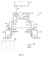
- FIG. 3 illustrates a schematic example of an aircraft 72.
- the aircraft 72 comprises a cockpit 74, a power plant analyzer 32, a first power plant 42, a second power plant 45 and sensing means 64.
- a cockpit 74 a cockpit 74
- a power plant analyzer 32 a first power plant 42
- a second power plant 45 a second power plant 45
- sensing means 64 a means for sensing the elements of the aircraft 72 used in understanding embodiments.
- the power plant analyzer 32 may be such as those described with reference to Figs. 2A and 2B above. However, in the embodiment illustrated in Fig. 3 , the power plant analyzer 32 comprises a processor 100, a memory 102 storing a computer program 76 and receiver 62.
- the memory 102 stores a computer program 76 comprising computer program instructions that control the operation of the power plant analyzer 32 when loaded into the processor 100.
- the computer program instructions 76 provide the logic and routines that enables the power plant analyzer 32 to perform the methods illustrated in Figs 4 & 5 .
- the processor 100 by reading the memory 102 is able to load and execute the computer program 76.
- the computer program may arrive at the power plant analyzer 32 via any suitable delivery mechanism 104.
- the delivery mechanism 104 may be, for example, a computer-readable storage medium, a computer program product, a memory device, a record medium such as a compact disc read-only memory (CD-ROM) or digital versatile disc (DVD), an article of manufacture that tangibly embodies the computer program 76.
- the delivery mechanism may be a signal configured to reliably transfer the computer program 76.
- the power plant analyzer 32 may propagate or transmit the computer program 76 as a computer data signal.
- the processor 100 in combination with the computer program 76, may be configured to carry out the functions of the analyzer 36 and/or the alert generator 50 and/or the controller 54 and/or the receiver 62 described above with regard to figures 2A and 2B .
- the power plant analyzer 32 may comprise any number of processors 100 and memories 102 that may operate separately or in combination.
- the receiver 62 which may for example be an interface, is configured to receive the first, second, third and fourth parameters 38, 44, 46, 48 from sensing means 64.
- the sensing means 64 for measuring the first and third parameters 38, 46 may, for example, be the fuel flow meters of the aircraft 72 and the sensing means 64 for measuring the second and fourth 44, 48 parameters may be any means suitable for measuring the exhaust gas temperature 60 and/or turbine gas temperature 58 of the first and second power plants 42, 45, for example a pyrometer and/or a thermocouple and/or a thermometer.
- the first power plant 42 is an average of a plurality of power plants 66. That is, the first and second parameters 38, 44 for the first power plant 42 may be an average of parameters measured for a plurality of power plants 66. Alternatively, the second power plant 45 may be an average of a plurality of power plants 66.
- the power plant analyzer 32 is configured to carry out an analysis of the first, second, third and fourth parameters as described above with reference to Figs. 2A and 2B and to generate an alert 52 in response to the analysis.
- the alert may be generated in the cock pit 74, and may, for example, be an audible and/or visual alert generated in the cock pit 74.
- the power plant analyzer 32 comprises a processor 100 and a memory 102 storing a computer program 76.
- the power plant analyzer 32 may comprise a system that is capable of machine learning for example, a neural network.
- Figure 4 illustrates a method 80 for analyzing a plurality of power plants.
- the method illustrated in Fig. 4 may be carried out, for example, by a power plant analyzer 32 as described above with reference to Figs. 2A, 2B and 3 .
- first parameter may be analyzed to provide an indication of fuel flow to a first power plant
- second parameter may be analyzed to provide an indication of fuel burned in the first power plant
- third parameter may be analyzed to provide an indication of fuel flow to a second power plant
- fourth parameter may be analyzed to provide an indication of fuel burned in the second power plant
- an alert is generated at block 84 in response to the analyzing block 82.
- the method 80 may be repeated periodically during the operation of the power plants.
- the method 80 may be repeated over any suitable period of time, for example, every 30 seconds, or every minute, or every 5 minutes, or every 10 minutes and so on.
- Figure 5 illustrates a further method 90 for analyzing a plurality of power plants.
- each power plant is in a substantially steady state. For example, power plants 1 and 2 as described above. This may be done as described above with reference to Fig. 2B .
- first and third parameters 38, 46 may comprise the fuel flow rate to the first and second power plants 42, 45 respectively and the second and fourth parameters 44, 48 may comprise the turbine temperature, for example exhaust gas temperature 60 or turbine gas temperature 58, of the first and second power plants 42, 45 respectively.
- the fuel flow rate to each power plant and turbine temperature of each power plant may be taken concurrently on all power plants to ensure that all power plants are at the same conditions and similar power setting when the parameters are recorded.
- the difference in the turbine temperature parameters between the power plants 42, 45 can be used to determine the expected difference in the fuel flow to the power plants 42, 45.
- the tolerance level may be varied depending upon factors such as the operating conditions of the power plants and the length of time that the power plants have been in steady state conditions.
- a fuel flow meter fault there may be, inter alia, a fuel flow meter fault, a temperature measurement fault, a power setting measurement fault, or a fuel leak in one of the first or second power plants 42, 45.
- the method of Fig. 5 may be repeated periodically during the time which the power plants 42, 45 are functioning.
- the method 90 may be repeated over any suitable period of time, for example, every 30 seconds, or every minute, or every 5 minutes, or every 10 minutes and so on.
- a parameter set comprises the parameters indicative of the fuel flow to and fuel burned in a power plant.
- a parameter set may come from any power plant or from an average of power plants.
- the above recited methods may be integrated over a period of time, such that the apparent fault would have to be indicated over some number of the valuations before an alert is generated. This reduces the potential for isolated data indications giving false alerts.
- Equation 1 is adjusted to compensate.
- K in equation 1 above may be a function of one or more parameters such as parameters indicative of flight conditions and/or power level.
- a second parameter, for example K2 may be included in equation 1 above to account for the power plants being at different power levels.
- K2 could be a function of power difference between the power plants, power level of the power plants and/or flight conditions.
- any parameters that are indicative of the fuel flow to the power plants and the fuel burned in the power plants may be used.
- the power plants may be gas turbine engines for use in other applications, such as marine gas turbine engines.
- the analysis described in the examples given above may be refined using further parameters measured from the first and/or second power plants.
- the blocks illustrated in the Figs 4 and 5 may represent steps in a method and/or sections of code in the computer program 76.
- the illustration of a particular order to the blocks does not necessarily imply that there is a required or preferred order for the blocks and the order and arrangement of the block may be varied. Furthermore, it may be possible for some steps to be omitted.
- the computer program when run on a computer, performs the steps of:
- the step of analyzing the first, second, third and fourth parameters comprises carrying out a differential analysis using the first, second, third and fourth parameters.
Landscapes
- Engineering & Computer Science (AREA)
- Chemical & Material Sciences (AREA)
- Combustion & Propulsion (AREA)
- Mechanical Engineering (AREA)
- General Engineering & Computer Science (AREA)
- Testing And Monitoring For Control Systems (AREA)
- Regulation And Control Of Combustion (AREA)
Abstract
analyzing means for analyzing a first parameter indicative of fuel flow to a first power plant, a second parameter indicative of fuel burned in the first power plant, a third parameter indicative of fuel flow to a second power plant and a fourth parameter indicative of fuel burned in the second power plant; and
alert generation means, responsive to the analyzing means, for generating an alert for the first or the second power plant.
Description
- Embodiments of the present invention relate to a power plant analyzer. In particular, they relate to a power plant analyzer for analyzing a plurality of power plants.
- During operation a fault, such as a fuel leak, may occur in a power plant.
- It would be beneficial to be able to detect faults such as fuel leaks during operation of a power plant so that an operator of the power plant may be alerted to the fault.
- Some embodiments of the present invention provide for a power plant analyzer for analyzing a plurality of power plants.
- According to various, but not necessarily all, embodiments of the invention there is provided a power plant analyzer for analyzing a plurality of power plants, comprising:
- analyzing means for analyzing a first parameter indicative of fuel flow to a first power plant, a second parameter indicative of fuel burned in the first power plant, a third parameter indicative of fuel flow to a second power plant and a fourth parameter indicative of fuel burned in the second power plant; and
- alert generation means, responsive to the analyzing means, for generating an alert for the first or the second power plant.
- According to various, but not necessarily all, embodiments of the invention there is provided a system comprising a power plant analyzer as described above and the first and second power plants.
- According to various, but not necessarily all, embodiments of the invention there is provided a method for analyzing a plurality of power plants, comprising:
- analyzing a first parameter indicative of fuel flow to a first power plant, a second parameter indicative of fuel burned in the first power plant, a third parameter indicative of fuel flow to a second power plant and a fourth parameter indicative of fuel burned in the second power plant; and
- generating, in response to analyzing, an alert for the first or the second power plant.
- According to various, but not necessarily all, embodiments of the invention there is provided a computer program, that when run on a computer, performs:
- analyzing a first parameter indicative of fuel flow to a first power plant, a second parameter indicative of fuel burned in the first power plant, a third parameter indicative of fuel flow to a second power plant and a fourth parameter indicative of fuel burned in the second power plant; and
- generating, in response to analyzing, an alert for the first or the second power plant.
- According to various, but not necessarily all, embodiments of the invention there is provided an apparatus comprising:
- at least one processor
- and at least one memory including computer program code the at least one memory and the computer program code configured to, with the at least one processor, cause the apparatus at least to
- analyzing a first parameter indicative of fuel flow to a first power plant, a second parameter indicative of fuel burned in the first power plant, a third parameter indicative of fuel flow to a second power plant and a fourth parameter indicative of fuel burned in the second power plant; and
- generating, in response to analyzing, an alert for the first or the second power plant.
- For a better understanding of various examples of embodiments of the present invention reference will now be made by way of example only to the accompanying drawings in which:
-
Figure 1 illustrates, in cross section, an example of a power plant; -
Figure 2A illustrates a schematic example of a power plant analyzer; -
Figure 2B illustrates a further schematic example of a power plant analyzer; -
Figure 3 illustrates a schematic example of an aircraft; -
Figure 4 illustrates a method for analyzing a plurality of power plants; and -
Figure 5 illustrates further method for analyzing a plurality of power plants. - The Figures, with the exception of
figure 1 , illustrate apower plant analyzer 32 for analyzing a plurality of power plants 34, comprisinganalyzing means 36 for analyzing afirst parameter 38 indicative of fuel flow to afirst power plant 42, asecond parameter 44 indicative of fuel burned in thefirst power plant 42, athird parameter 46 indicative of fuel flow to asecond power plant 45 and afourth parameter 48 indicative of fuel burned in thesecond power plant 45; and alert generation means 50, responsive to the analyzing means 36, for generating analert 52 for the first or thesecond power plant -
Figure 1 illustrates an example of apower plant power plant gas turbine engine 10 for use with a vehicle. For example, the gas turbine engine may be an aerogas turbine engine 70. - In
fig. 1 thegas turbine engine 10 comprises, in axial flow series, anair intake 11, apropulsive fan 12, an intermediate pressure compressor 13, ahigh pressure compressor 14, acombustor 15, a turbine arrangement comprising ahigh pressure turbine 16, anintermediate pressure turbine 17 and alow pressure turbine 18, and anexhaust nozzle 19. Thegas turbine engine 10 illustrated infigure 1 may be an aero gas turbine engine and is an example of what the first and/orsecond power plants - The
gas turbine engine 10 operates in a conventional manner so that air entering theintake 11 is accelerated by thefan 12 which produces two air flows: a first air flow into the intermediate pressure compressor 13 and a second air flow which provides propulsive thrust. The intermediate pressure compressor compresses the air flow directed into it before delivering that air to thehigh pressure compressor 14 where further compression takes place. - The compressed air exhausted from the
high pressure compressor 14 is directed into thecombustor 15 where it is mixed with fuel and the mixture combusted. The resultant hot combustion products then expand through, and thereby drive, the high, intermediate andlow pressure turbines nozzle 19 to provide additional propulsive thrust. The high, intermediate andlow pressure turbines intermediate pressure compressors 14 and 13 and thefan 12 by suitable interconnectingshafts - The configuration of the
gas turbine engine 10 illustrated infigure 1 is shown as an example only. Other configurations are also possible. For example, thegas turbine engine 10 may not include the intermediate pressure components and/or may comprise a booster compressor. Furthermore, the gas turbine engine may, for example, comprise a turboprop or a helicopter rotor via a gearbox. -
Figure 2A illustrates a schematic example of apower plant analyzer 32. Thepower plant analyzer 32 may, for example, be used to analyze a plurality of power plants 34. The plurality of power plants may comprise or may all be a power plant such as the power plant illustrated infigure 1 . - The
power plant analyzer 32 comprises analyzing means 36 for analyzing a plurality of power plants 34. For example, the analyzing means 36 may be configured to analyze a plurality of parameters derived from afirst power plant 42 and asecond power plant 45. The first orsecond power plant figure 3 ). - The
power plant analyzer 32 further comprises alert generation means 50 for generating analert 52 in response to the analyzing means 36 carrying out an analysis of a plurality of power plants 34. The alert generation means may, for example, be configured to generate an audible and/or visual alert. Additionally/alternatively the alert generation means may, for example, be configured to generate a control signal that, for example, causes an audible and/or visual alert. - The
analyzing means 36 is for analyzing afirst parameter 38 that is indicative of thefuel flow 40 to afirst power plant 42, asecond parameter 44 that is indicative of fuel burned in thefirst power plant 42, athird parameter 46 that is indicative of thefuel flow 40 to asecond power plant 45 and afourth parameter 48 that is indicative of the fuel burned in thesecond power plant 45. - The first, second, third and fourth parameters may be measured concurrently for the first and second power plants.
- For example, the
first parameter 38 may comprise the fuel flow rate to thefirst power plant 42 and thethird parameter 46 may comprise the fuel flow rate to thesecond power plant 45. Thesecond parameter 44 may comprise the turbine gas temperature 58 and/or the exhaust gas temperature 60 of thefirst power plant 42. Thefourth parameter 48 may comprise the turbine gas temperature 58 and/or the exhaust gas temperature 60 of the second power plant 45 (Seefigure 3 ). - In embodiments, the
analyzing means 36 is configured to carry out a differential analysis of the first, second, third andfourth parameters - In some embodiments the analyzing means is configured to carry out a differential analysis between the first and
third parameters fourth parameters - For example, the differential analysis between the first and
third parameters fourth parameters third parameters fourth parameters - Additionally/alternatively the differential analysis between the first and
third parameters fourth parameters - The analyzing means 36 is configured to compare the first and second results from the differential analysis.
- In other embodiments the analyzing means 36 is configured to carry out a differential analysis between the first and
second parameters fourth parameters - The differential analysis of the four parameters provides a comparison of the fuel flowing to the
first power plant 42 and thesecond power plant 45 and the fuel burned in thefirst power plant 42 and thesecond power plant 45. The results of the differential analysis may indicate that there is an unexpected difference between the analyzed power plants and an alert may be generated on this basis. For example, a fuel leak downstream of the fuel flow meter 64 (seefigure 3 ) in the first orsecond power plant - It is known that as a power plant ages it will become less efficient due to deterioration. As a power plant deteriorates more fuel will be burned in the power plant to obtain a given power output, for example thrust. Burning more fuel in the power plant will lead to a higher temperature of exhaust gases from the power plant.
- Therefore, for power plants that are in substantially the same operating conditions and at substantially the same power level there may be a difference in the amount of fuel flowing to the power plants if one of the power plants is older than the others.
- The inventors have realized that if, in attempting to detect a fuel leak in the first or
second power plant - This means that the margins required in a simple comparison of fuel flow to the power plants must be large to prevent false fuel leak alerts due to differences between the power plants due to deterioration, for example. Small fuel leaks may be missed in such a system which could be very problematic in embodiments where the power plants are aero gas turbine engines, for example.
- The inventors have realized that by also considering parameters indicative of the fuel burned in the power plants this allows for greater sensitivity in the detection of fuel leaks, for example.
- There may be other causes of expected differences between the first and second power plant, 42, 45. For example, in an embodiment where the power plants are aero gas turbine engines, more electrical and/or hydraulic energy may be being drawn from a particular engine, again requiring a greater fuel flow to that engine.
- Returning to
fig 2A , the analysis may indicate an unexpected difference between the fuel flowing to the first orsecond power plant second power plant - As described above, by analyzing parameters indicating the fuel flowing to the
power plants power plants - The alert generation means 50 is configured to respond to the analyzing means 36. The alert generation means may be configured to respond to the analyzing means 36 determining from the four
parameters second power plants - For example, the alert generation means 50 may be configured to generate an alert 52 if it is determined that there is a difference between the first and
second power plants - The alert generation means 50 may be responsive to the analyzing means 36 to generate an alert 52 indicating that there is a possible fuel leak in the first or
second power plant Fig. 2B below. - The
first power plant 42 and/or thesecond power plant 45 may be a power plant such as the one illustrated inFig. 1 . Thefirst power plant 42 and/or thesecond power plant 45 may be a gas turbine engine such as an aerogas turbine engine 70. -
Figure 2B illustrates a further schematic example of apower plant analyzer 32. Thepower plant analyzer 32 ofFig. 2B comprises analyzing means 36 and alert generation means 50 as described above with reference toFig. 2A . Thepower plant analyzer 32 ofFig. 2B further comprises control means 54 and receiving means 62. - The
controller 54 is for identifying when the first andsecond power plants analyzer 36 and/or thealert generator 50 in response to identifying that the first andsecond power plants - For example, the
controller 54 may identify that a power plant is in a substantially steady state by establishing that the power plant has remained within ±1-2% of some power indicating parameter over a particular time period, such as 30 seconds for example. - As a further example, the
controller 54 may identify that a power plant is in a substantially steady state, in the case where the power plant is an aero engine, when the aircraft to which the aero engine is comprised, is within ± 500 feet from a flight path and the speed of the aircraft measured in Mach number remains within ± 0.2 over a period of 30 seconds for example. - Alternatively, the aircraft climb rate may be determined to be at a substantially steady rate over a predetermined period of time such as 30 seconds. However, any suitable indication, such as a parameter, that provide that the power plant is in a substantially stable state condition may be used. The time periods mentioned above are given by way of examples only and any suitable time periods may be used. The time periods used may vary in dependence on the operating state of the power plants.
- The
controller 54 may also be for identifying when the first andsecond power plants analyzer 36 and/or thealert generator 50 in response to identifying that the first andsecond power plants - The
controller 54 may establish that both power plants are within ±1-2% of a parameter indicating the power level of the power plant. For example, one or more of the following may be used. The Engine Pressure Ratio (EPR), the speed of a fan at the front of a power plant (in the case of the power plant being a gas turbine engine) and/or the turbine power ratio (TPR). However, any suitable indication of the power level of a power plant may be used. - The
receiver 62 is for receiving the first, second, third andfourth parameters - An example of the operation of the
power plant analyzer 32 illustrated inFig. 2B will be described below in relation toFig. 5 . -
Figure 3 illustrates a schematic example of anaircraft 72. Theaircraft 72 comprises acockpit 74, apower plant analyzer 32, afirst power plant 42, asecond power plant 45 and sensing means 64. For the sake of clarity only the elements of theaircraft 72 used in understanding embodiments are illustrated. - The
power plant analyzer 32 may be such as those described with reference toFigs. 2A and 2B above. However, in the embodiment illustrated inFig. 3 , thepower plant analyzer 32 comprises aprocessor 100, amemory 102 storing acomputer program 76 andreceiver 62. - The
memory 102 stores acomputer program 76 comprising computer program instructions that control the operation of thepower plant analyzer 32 when loaded into theprocessor 100. Thecomputer program instructions 76 provide the logic and routines that enables thepower plant analyzer 32 to perform the methods illustrated inFigs 4 & 5 . Theprocessor 100 by reading thememory 102 is able to load and execute thecomputer program 76. - The computer program may arrive at the
power plant analyzer 32 via anysuitable delivery mechanism 104. Thedelivery mechanism 104 may be, for example, a computer-readable storage medium, a computer program product, a memory device, a record medium such as a compact disc read-only memory (CD-ROM) or digital versatile disc (DVD), an article of manufacture that tangibly embodies thecomputer program 76. The delivery mechanism may be a signal configured to reliably transfer thecomputer program 76. - The
power plant analyzer 32 may propagate or transmit thecomputer program 76 as a computer data signal. - The
processor 100, in combination with thecomputer program 76, may be configured to carry out the functions of theanalyzer 36 and/or thealert generator 50 and/or thecontroller 54 and/or thereceiver 62 described above with regard tofigures 2A and 2B . - In the illustrated example only a
single processor 100 andmemory 102 are shown for clarity. However, thepower plant analyzer 32 may comprise any number ofprocessors 100 andmemories 102 that may operate separately or in combination. - The
receiver 62, which may for example be an interface, is configured to receive the first, second, third andfourth parameters third parameters aircraft 72 and the sensing means 64 for measuring the second and fourth 44, 48 parameters may be any means suitable for measuring the exhaust gas temperature 60 and/or turbine gas temperature 58 of the first andsecond power plants - In the illustrated embodiment the
first power plant 42 is an average of a plurality ofpower plants 66. That is, the first andsecond parameters first power plant 42 may be an average of parameters measured for a plurality ofpower plants 66. Alternatively, thesecond power plant 45 may be an average of a plurality ofpower plants 66. - The
power plant analyzer 32 is configured to carry out an analysis of the first, second, third and fourth parameters as described above with reference toFigs. 2A and 2B and to generate an alert 52 in response to the analysis. - The alert may be generated in the
cock pit 74, and may, for example, be an audible and/or visual alert generated in thecock pit 74. - In the example illustrated in
Fig. 3 thepower plant analyzer 32 comprises aprocessor 100 and amemory 102 storing acomputer program 76. - Additionally/alternatively, the
power plant analyzer 32 may comprise a system that is capable of machine learning for example, a neural network. -
Figure 4 illustrates amethod 80 for analyzing a plurality of power plants. The method illustrated inFig. 4 may be carried out, for example, by apower plant analyzer 32 as described above with reference toFigs. 2A, 2B and3 . - At
block 82 the first, second, third andfourth parameters - If the analysis indicates that there is an unexpected difference between the first and
second power plants block 84 in response to the analyzingblock 82. - If the analysis indicates that there is no unexpected difference between the first and second power plants no alert is generated at
block 86. - The
method 80 may be repeated periodically during the operation of the power plants. Themethod 80 may be repeated over any suitable period of time, for example, every 30 seconds, or every minute, or every 5 minutes, or every 10 minutes and so on. -
Figure 5 illustrates afurther method 90 for analyzing a plurality of power plants. - At
block 92 it is identified that each power plant is in a substantially steady state. For example, power plants 1 and 2 as described above. This may be done as described above with reference toFig. 2B . - At
block 94 it is identified that the power plants are at substantially the same power level. This may be done as described above with reference toFig. 2B . - At
block 95 the first, second, third andfourth parameters - As discussed above, the first and
third parameters second power plants fourth parameters second power plants - The fuel flow rate to each power plant and turbine temperature of each power plant may be taken concurrently on all power plants to ensure that all power plants are at the same conditions and similar power setting when the parameters are recorded.
- If the
power plants 
Where: - K is a constant determined from simulations and/or modeling;
- Δ turbine temperature is the difference between the turbine temperatures of the power plants and
- Δ Fuel flow % is the fuel flow difference between the power plants taken as a percentage of the fuel flowing to one power plant or an average of the fuel flowing to both power plants.
- Thus the difference in the turbine temperature parameters between the
power plants power plants 
can be constructed as a measure of difference between the power plants, and whether one of the power plants is not following the expected deterioration trend. If the analysis determines that the parameter P is above or below some predetermined tolerance this implies that there may be an issue with one of the first andsecond power plants - The tolerance level may be varied depending upon factors such as the operating conditions of the power plants and the length of time that the power plants have been in steady state conditions.
- For example, there may be, inter alia, a fuel flow meter fault, a temperature measurement fault, a power setting measurement fault, or a fuel leak in one of the first or
second power plants - If it is determined that there is something uncertain about one of the
power plants block 95 an alert is generated atblock 96. - If the
power plants block 98. - The method of
Fig. 5 may be repeated periodically during the time which thepower plants method 90 may be repeated over any suitable period of time, for example, every 30 seconds, or every minute, or every 5 minutes, or every 10 minutes and so on. - The methods may be performed in relation to any pair of parameter sets. A parameter set comprises the parameters indicative of the fuel flow to and fuel burned in a power plant. A parameter set may come from any power plant or from an average of power plants.
- In some embodiments the above recited methods may be integrated over a period of time, such that the apparent fault would have to be indicated over some number of the valuations before an alert is generated. This reduces the potential for isolated data indications giving false alerts.
- In the analysis described with reference to
figure 5 , the analysis may be carried out without the engines being at substantially the same power level. In this situation equation 1 is adjusted to compensate. For example, K in equation 1 above may be a function of one or more parameters such as parameters indicative of flight conditions and/or power level. Alternatively/additionally a second parameter, for example K2, may be included in equation 1 above to account for the power plants being at different power levels. K2 could be a function of power difference between the power plants, power level of the power plants and/or flight conditions. - Although in the description above specific examples of the first, second, third and fourth parameters have been given, any parameters that are indicative of the fuel flow to the power plants and the fuel burned in the power plants may be used.
- Furthermore, although in the examples described above the same parameters have been used for each power plant, in embodiments different parameters may be used for some or all of the power plants analyzed.
- Although in the examples described above two power plants have been described, in embodiments more than two power plants may be used in the analysis.
- Although examples described above have been described with reference to aero gas turbine engines, the power plants may be gas turbine engines for use in other applications, such as marine gas turbine engines.
- The analysis described in the examples given above may be refined using further parameters measured from the first and/or second power plants.
- The blocks illustrated in the
Figs 4 and 5 may represent steps in a method and/or sections of code in thecomputer program 76. The illustration of a particular order to the blocks does not necessarily imply that there is a required or preferred order for the blocks and the order and arrangement of the block may be varied. Furthermore, it may be possible for some steps to be omitted. - For example, the computer program, when run on a computer, performs the steps of:
- analyzing a first parameter indicative of fuel flow to a first power plant, a second parameter indicative of fuel burned in the first power plant, a third parameter indicative of fuel flow to a second power plant and a fourth parameter indicative of fuel burned in the second power plant; and
- generating, in response to analyzing, an alert for the first or the second power plant.
- Additionally, the step of analyzing the first, second, third and fourth parameters comprises carrying out a differential analysis using the first, second, third and fourth parameters.
- Although embodiments of the present invention have been described in the preceding paragraphs with reference to various examples, it should be appreciated that modifications to the examples given can be made without departing from the scope of the invention as claimed.
- Features described in the preceding description may be used in combinations other than the combinations explicitly described.
- Although functions have been described with reference to certain features, those functions may be performable by other features whether described or not.
- Although features have been described with reference to certain embodiments, those features may also be present in other embodiments whether described or not.
Claims (15)
- A power plant analyzer (32) for analyzing a plurality of power plants (34), comprising:analyzing means (36) for analyzing a first parameter (38) indicative of fuel flow to a first power plant (42), a second parameter (44) indicative of fuel burned in the first power plant (42), a third parameter (46) indicative of fuel flow to a second power plant (45) and a fourth parameter (48) indicative of fuel burned in the second power plant (45); andalert generation means (50), responsive to the analyzing means (36), for generating an alert (52) for the first or the second power plant (42,45).
- A power plant analyzer (32) as claimed in claim 1, wherein the analyzing means (36) is configured to carry out a differential analysis using the first, second, third and fourth parameters (38,44,46,48).
- A power plant analyzer (32) as claimed in claim 1 or 2, wherein the analyzing means (36) is configured to carry out a differential analysis between the first and third parameters (38,46) to produce a first result, and to carry out a differential analysis between the second and fourth parameters (44,48) to produce a second result, and to compare the first and second results.
- A power plant analyzer (32) as claimed in claim 2 or 3, wherein the differential analysis comprises calculating a difference between the first and third parameters (38,46) and the second and fourth parameters (44,48).
- A power plant analyzer (32) as claimed in claim 2 or 3, wherein the differential analysis comprises calculating a ratio between the first and third parameters (38,46) and the second and fourth parameters (44,48).
- A power plant analyzer (32) as claimed in claim 1 or 2, wherein the analyzing means (36) is configured to carry out a differential analysis between the first and second parameters (38,44) to produce a first result, and to carry out a differential analysis between the third and fourth parameters (46,48) to produce a second result and to compare the first and second results.
- A power plant analyzer (32) as claimed in any preceding claim, further comprising control means for identifying when the first and second power plants (42,45) are in a substantially steady state and for enabling the analyzing means (36) and/or the alert generation means (50), in response to identifying that the first and second power plants (42,45) are in a substantially steady state.
- A power plant analyzer (32) as claimed in any preceding claim, further comprising control means (54) for identifying when the first and second power plants (42,45) are at substantially the same power level and for enabling the analyzing means (36) and/or the alert generation means(50), in response to identifying that the first and second power plants (42,45) are at substantially the same power level.
- A power plant analyzer (32) as claimed in any preceding claim, wherein the first parameter (38) is indicative of a fuel flow rate to the first power plant (42) and the third parameter (46) is indicative of a fuel flow rate to the second power plant (45).
- A power plant analyzer (32) as claimed in any preceding claim, wherein the second parameter (44) is indicative of a turbine gas temperature (58) or an exhaust gas temperature (60) of the first power plant (42) and the fourth parameter (48) is indicative of a turbine gas temperature (58) or an exhaust gas temperature (60) of the second power plant (45).
- A power plant analyzer (32) as claimed in any preceding claim, further comprising receiving means (62) for receiving the first, second, third and fourth parameters (38,44,46,48) from sensing means (64) located to measure the first, second, third and fourth parameters (38,44,46,48) in the first and second power plants (42,45).
- A system comprising a power plant analyzer (32) as claimed in any preceding claim and the first and second power plants.
- A method for analyzing a plurality of power plants, comprising:analyzing a first parameter indicative of fuel flow to a first power plant, a second parameter indicative of fuel burned in the first power plant, a third parameter indicative of fuel flow to a second power plant and a fourth parameter indicative of fuel burned in the second power plant; andgenerating, in response to analyzing, an alert for the first or the second power plant.
- A method as claimed in claim 13, wherein analyzing the first, second, third and fourth parameters comprises carrying out a differential analysis using the first, second, third and fourth parameters.
- A method as claimed in claim 13 or 14, wherein analyzing the first, second, third and fourth parameters comprises carrying out a differential analysis between the first and third parameters to produce a first result, and to carry out a differential analysis between the second and fourth parameters to produce a second result, and comparing the first and second results.
Applications Claiming Priority (1)
| Application Number | Priority Date | Filing Date | Title |
|---|---|---|---|
| GBGB1116413.4A GB201116413D0 (en) | 2011-09-23 | 2011-09-23 | A power plant analyzer for analyzing a plurality of power plants |
Publications (3)
| Publication Number | Publication Date |
|---|---|
| EP2587029A2 true EP2587029A2 (en) | 2013-05-01 |
| EP2587029A3 EP2587029A3 (en) | 2015-12-30 |
| EP2587029B1 EP2587029B1 (en) | 2017-03-01 |
Family
ID=44937707
Family Applications (1)
| Application Number | Title | Priority Date | Filing Date |
|---|---|---|---|
| EP12184949.1A Not-in-force EP2587029B1 (en) | 2011-09-23 | 2012-09-19 | A power plant analyzer for analyzing a plurality of power plants |
Country Status (3)
| Country | Link |
|---|---|
| US (1) | US8707769B2 (en) |
| EP (1) | EP2587029B1 (en) |
| GB (1) | GB201116413D0 (en) |
Families Citing this family (1)
| Publication number | Priority date | Publication date | Assignee | Title |
|---|---|---|---|---|
| US10260425B2 (en) | 2016-05-05 | 2019-04-16 | United Technologies Corporation | Leak detection, isolation and accommodation assembly for gas turbine engines |
Family Cites Families (6)
| Publication number | Priority date | Publication date | Assignee | Title |
|---|---|---|---|---|
| US4546353A (en) * | 1984-02-06 | 1985-10-08 | The United States Of America As Represented By The Secretary Of The Air Force | Asymmetric thrust warning system for dual engine aircraft |
| US5285638A (en) | 1991-05-28 | 1994-02-15 | Telectro-Mek, Inc. | Method and apparatus for maximizing fuel efficiency for jet engines |
| JPH10103081A (en) | 1996-09-27 | 1998-04-21 | Mitsubishi Heavy Ind Ltd | Control method for plural gas turbines |
| US6498978B2 (en) | 2001-05-18 | 2002-12-24 | General Electric Company | System and method for monitoring thermal state to normalize engine trending data |
| RU2250382C2 (en) | 2003-04-04 | 2005-04-20 | Открытое акционерное общество "Техприбор" | Onboard monitoring system for engine at limited temperature, fuel parameters and pressure |
| US8290683B2 (en) * | 2010-02-16 | 2012-10-16 | Telectro-Mek, Inc. | Apparatus and method for reducing aircraft fuel consumption |
-
2011
- 2011-09-23 GB GBGB1116413.4A patent/GB201116413D0/en not_active Ceased
-
2012
- 2012-09-19 US US13/622,627 patent/US8707769B2/en not_active Expired - Fee Related
- 2012-09-19 EP EP12184949.1A patent/EP2587029B1/en not_active Not-in-force
Non-Patent Citations (1)
| Title |
|---|
| None |
Also Published As
| Publication number | Publication date |
|---|---|
| EP2587029A3 (en) | 2015-12-30 |
| US20130074588A1 (en) | 2013-03-28 |
| US8707769B2 (en) | 2014-04-29 |
| GB201116413D0 (en) | 2011-11-02 |
| EP2587029B1 (en) | 2017-03-01 |
Similar Documents
| Publication | Publication Date | Title |
|---|---|---|
| EP2458178B2 (en) | Turbine performance diagnositic system and methods | |
| US8321118B2 (en) | Operations support systems and methods with power assurance | |
| Li et al. | A method to improve the robustness of gas turbine gas-path fault diagnosis against sensor faults | |
| EP2207072A2 (en) | Operations support systems and methods with engine diagnostics | |
| CA2956999C (en) | Automated system and method for generating engine test cell analytics and diagnostics | |
| US9644534B2 (en) | Systems and methods for implementing engine cycle count | |
| CN109073508A (en) | Troubleshooting during testing of turbo units | |
| US10551818B2 (en) | Fault detection methods and systems | |
| US7801695B2 (en) | Operations support systems and methods with model-based torque estimates | |
| EP3839684A1 (en) | Method and system for diagnosing an engine or an aircraft | |
| Ntantis et al. | The impact of measurement noise in GPA diagnostic analysis of a gas turbine engine | |
| EP1930568A1 (en) | Method and system for monitoring process states of an internal combustion engine | |
| Verbist et al. | Experience with gas path analysis for on-wing turbofan condition monitoring | |
| EP2587029B1 (en) | A power plant analyzer for analyzing a plurality of power plants | |
| KR20230147683A (en) | Plant monitoring methods, plant monitoring devices and plant monitoring programs | |
| US20150338312A1 (en) | Systems and Methods for Implementing Engine Cycle Count | |
| Verbist et al. | Experience with gas path analysis for on-wing turbofan condition monitoring | |
| EP4112886B1 (en) | In-flight measured propulsion mass flow and thrust on aircraft | |
| US9933336B2 (en) | Gas turbine having fuel monitoring | |
| RU2522275C2 (en) | Method for determining technical state of power plants | |
| Zarate et al. | Computation and monitoring of the deviations of gas turbine unmeasured parameters | |
| Jombo et al. | Towards an automated system for industrial gas turbine acceptance testing | |
| US11248989B2 (en) | System and method for analyzing engine test data in real time | |
| Bauer et al. | Fully automated model based performance analysis procedure for online and offline applications | |
| KR102224983B1 (en) | Inspecting and Diagnosing Device For Gas Turbin Combustor |
Legal Events
| Date | Code | Title | Description |
|---|---|---|---|
| PUAI | Public reference made under article 153(3) epc to a published international application that has entered the european phase |
Free format text: ORIGINAL CODE: 0009012 |
|
| AK | Designated contracting states |
Kind code of ref document: A2 Designated state(s): AL AT BE BG CH CY CZ DE DK EE ES FI FR GB GR HR HU IE IS IT LI LT LU LV MC MK MT NL NO PL PT RO RS SE SI SK SM TR |
|
| AX | Request for extension of the european patent |
Extension state: BA ME |
|
| RAP1 | Party data changed (applicant data changed or rights of an application transferred) |
Owner name: ROLLS-ROYCE PLC |
|
| PUAL | Search report despatched |
Free format text: ORIGINAL CODE: 0009013 |
|
| AK | Designated contracting states |
Kind code of ref document: A3 Designated state(s): AL AT BE BG CH CY CZ DE DK EE ES FI FR GB GR HR HU IE IS IT LI LT LU LV MC MK MT NL NO PL PT RO RS SE SI SK SM TR |
|
| AX | Request for extension of the european patent |
Extension state: BA ME |
|
| RIC1 | Information provided on ipc code assigned before grant |
Ipc: F02C 9/42 20060101AFI20151126BHEP |
|
| 17P | Request for examination filed |
Effective date: 20160630 |
|
| RBV | Designated contracting states (corrected) |
Designated state(s): AL AT BE BG CH CY CZ DE DK EE ES FI FR GB GR HR HU IE IS IT LI LT LU LV MC MK MT NL NO PL PT RO RS SE SI SK SM TR |
|
| GRAJ | Information related to disapproval of communication of intention to grant by the applicant or resumption of examination proceedings by the epo deleted |
Free format text: ORIGINAL CODE: EPIDOSDIGR1 |
|
| GRAP | Despatch of communication of intention to grant a patent |
Free format text: ORIGINAL CODE: EPIDOSNIGR1 |
|
| GRAP | Despatch of communication of intention to grant a patent |
Free format text: ORIGINAL CODE: EPIDOSNIGR1 |
|
| INTG | Intention to grant announced |
Effective date: 20161018 |
|
| STAA | Information on the status of an ep patent application or granted ep patent |
Free format text: STATUS: GRANT OF PATENT IS INTENDED |
|
| GRAS | Grant fee paid |
Free format text: ORIGINAL CODE: EPIDOSNIGR3 |
|
| GRAA | (expected) grant |
Free format text: ORIGINAL CODE: 0009210 |
|
| STAA | Information on the status of an ep patent application or granted ep patent |
Free format text: STATUS: THE PATENT HAS BEEN GRANTED |
|
| AK | Designated contracting states |
Kind code of ref document: B1 Designated state(s): AL AT BE BG CH CY CZ DE DK EE ES FI FR GB GR HR HU IE IS IT LI LT LU LV MC MK MT NL NO PL PT RO RS SE SI SK SM TR |
|
| REG | Reference to a national code |
Ref country code: GB Ref legal event code: FG4D |
|
| REG | Reference to a national code |
Ref country code: CH Ref legal event code: EP Ref country code: AT Ref legal event code: REF Ref document number: 871664 Country of ref document: AT Kind code of ref document: T Effective date: 20170315 |
|
| REG | Reference to a national code |
Ref country code: IE Ref legal event code: FG4D |
|
| REG | Reference to a national code |
Ref country code: DE Ref legal event code: R096 Ref document number: 602012029147 Country of ref document: DE |
|
| REG | Reference to a national code |
Ref country code: NL Ref legal event code: MP Effective date: 20170301 |
|
| REG | Reference to a national code |
Ref country code: LT Ref legal event code: MG4D |
|
| REG | Reference to a national code |
Ref country code: AT Ref legal event code: MK05 Ref document number: 871664 Country of ref document: AT Kind code of ref document: T Effective date: 20170301 |
|
| PG25 | Lapsed in a contracting state [announced via postgrant information from national office to epo] |
Ref country code: HR Free format text: LAPSE BECAUSE OF FAILURE TO SUBMIT A TRANSLATION OF THE DESCRIPTION OR TO PAY THE FEE WITHIN THE PRESCRIBED TIME-LIMIT Effective date: 20170301 Ref country code: FI Free format text: LAPSE BECAUSE OF FAILURE TO SUBMIT A TRANSLATION OF THE DESCRIPTION OR TO PAY THE FEE WITHIN THE PRESCRIBED TIME-LIMIT Effective date: 20170301 Ref country code: GR Free format text: LAPSE BECAUSE OF FAILURE TO SUBMIT A TRANSLATION OF THE DESCRIPTION OR TO PAY THE FEE WITHIN THE PRESCRIBED TIME-LIMIT Effective date: 20170602 Ref country code: LT Free format text: LAPSE BECAUSE OF FAILURE TO SUBMIT A TRANSLATION OF THE DESCRIPTION OR TO PAY THE FEE WITHIN THE PRESCRIBED TIME-LIMIT Effective date: 20170301 Ref country code: NO Free format text: LAPSE BECAUSE OF FAILURE TO SUBMIT A TRANSLATION OF THE DESCRIPTION OR TO PAY THE FEE WITHIN THE PRESCRIBED TIME-LIMIT Effective date: 20170601 |
|
| PG25 | Lapsed in a contracting state [announced via postgrant information from national office to epo] |
Ref country code: AT Free format text: LAPSE BECAUSE OF FAILURE TO SUBMIT A TRANSLATION OF THE DESCRIPTION OR TO PAY THE FEE WITHIN THE PRESCRIBED TIME-LIMIT Effective date: 20170301 Ref country code: LV Free format text: LAPSE BECAUSE OF FAILURE TO SUBMIT A TRANSLATION OF THE DESCRIPTION OR TO PAY THE FEE WITHIN THE PRESCRIBED TIME-LIMIT Effective date: 20170301 Ref country code: RS Free format text: LAPSE BECAUSE OF FAILURE TO SUBMIT A TRANSLATION OF THE DESCRIPTION OR TO PAY THE FEE WITHIN THE PRESCRIBED TIME-LIMIT Effective date: 20170301 Ref country code: BG Free format text: LAPSE BECAUSE OF FAILURE TO SUBMIT A TRANSLATION OF THE DESCRIPTION OR TO PAY THE FEE WITHIN THE PRESCRIBED TIME-LIMIT Effective date: 20170601 Ref country code: SE Free format text: LAPSE BECAUSE OF FAILURE TO SUBMIT A TRANSLATION OF THE DESCRIPTION OR TO PAY THE FEE WITHIN THE PRESCRIBED TIME-LIMIT Effective date: 20170301 Ref country code: ES Free format text: LAPSE BECAUSE OF FAILURE TO SUBMIT A TRANSLATION OF THE DESCRIPTION OR TO PAY THE FEE WITHIN THE PRESCRIBED TIME-LIMIT Effective date: 20170301 |
|
| REG | Reference to a national code |
Ref country code: FR Ref legal event code: PLFP Year of fee payment: 6 |
|
| PG25 | Lapsed in a contracting state [announced via postgrant information from national office to epo] |
Ref country code: NL Free format text: LAPSE BECAUSE OF FAILURE TO SUBMIT A TRANSLATION OF THE DESCRIPTION OR TO PAY THE FEE WITHIN THE PRESCRIBED TIME-LIMIT Effective date: 20170301 |
|
| PG25 | Lapsed in a contracting state [announced via postgrant information from national office to epo] |
Ref country code: SK Free format text: LAPSE BECAUSE OF FAILURE TO SUBMIT A TRANSLATION OF THE DESCRIPTION OR TO PAY THE FEE WITHIN THE PRESCRIBED TIME-LIMIT Effective date: 20170301 Ref country code: EE Free format text: LAPSE BECAUSE OF FAILURE TO SUBMIT A TRANSLATION OF THE DESCRIPTION OR TO PAY THE FEE WITHIN THE PRESCRIBED TIME-LIMIT Effective date: 20170301 Ref country code: CZ Free format text: LAPSE BECAUSE OF FAILURE TO SUBMIT A TRANSLATION OF THE DESCRIPTION OR TO PAY THE FEE WITHIN THE PRESCRIBED TIME-LIMIT Effective date: 20170301 Ref country code: RO Free format text: LAPSE BECAUSE OF FAILURE TO SUBMIT A TRANSLATION OF THE DESCRIPTION OR TO PAY THE FEE WITHIN THE PRESCRIBED TIME-LIMIT Effective date: 20170301 Ref country code: IT Free format text: LAPSE BECAUSE OF FAILURE TO SUBMIT A TRANSLATION OF THE DESCRIPTION OR TO PAY THE FEE WITHIN THE PRESCRIBED TIME-LIMIT Effective date: 20170301 |
|
| PG25 | Lapsed in a contracting state [announced via postgrant information from national office to epo] |
Ref country code: PT Free format text: LAPSE BECAUSE OF FAILURE TO SUBMIT A TRANSLATION OF THE DESCRIPTION OR TO PAY THE FEE WITHIN THE PRESCRIBED TIME-LIMIT Effective date: 20170703 Ref country code: IS Free format text: LAPSE BECAUSE OF FAILURE TO SUBMIT A TRANSLATION OF THE DESCRIPTION OR TO PAY THE FEE WITHIN THE PRESCRIBED TIME-LIMIT Effective date: 20170701 Ref country code: SM Free format text: LAPSE BECAUSE OF FAILURE TO SUBMIT A TRANSLATION OF THE DESCRIPTION OR TO PAY THE FEE WITHIN THE PRESCRIBED TIME-LIMIT Effective date: 20170301 Ref country code: PL Free format text: LAPSE BECAUSE OF FAILURE TO SUBMIT A TRANSLATION OF THE DESCRIPTION OR TO PAY THE FEE WITHIN THE PRESCRIBED TIME-LIMIT Effective date: 20170301 |
|
| REG | Reference to a national code |
Ref country code: DE Ref legal event code: R097 Ref document number: 602012029147 Country of ref document: DE |
|
| PLBE | No opposition filed within time limit |
Free format text: ORIGINAL CODE: 0009261 |
|
| STAA | Information on the status of an ep patent application or granted ep patent |
Free format text: STATUS: NO OPPOSITION FILED WITHIN TIME LIMIT |
|
| PG25 | Lapsed in a contracting state [announced via postgrant information from national office to epo] |
Ref country code: DK Free format text: LAPSE BECAUSE OF FAILURE TO SUBMIT A TRANSLATION OF THE DESCRIPTION OR TO PAY THE FEE WITHIN THE PRESCRIBED TIME-LIMIT Effective date: 20170301 |
|
| 26N | No opposition filed |
Effective date: 20171204 |
|
| PG25 | Lapsed in a contracting state [announced via postgrant information from national office to epo] |
Ref country code: SI Free format text: LAPSE BECAUSE OF FAILURE TO SUBMIT A TRANSLATION OF THE DESCRIPTION OR TO PAY THE FEE WITHIN THE PRESCRIBED TIME-LIMIT Effective date: 20170301 |
|
| REG | Reference to a national code |
Ref country code: CH Ref legal event code: PL |
|
| PG25 | Lapsed in a contracting state [announced via postgrant information from national office to epo] |
Ref country code: MC Free format text: LAPSE BECAUSE OF FAILURE TO SUBMIT A TRANSLATION OF THE DESCRIPTION OR TO PAY THE FEE WITHIN THE PRESCRIBED TIME-LIMIT Effective date: 20170301 |
|
| REG | Reference to a national code |
Ref country code: IE Ref legal event code: MM4A |
|
| REG | Reference to a national code |
Ref country code: BE Ref legal event code: MM Effective date: 20170930 |
|
| PG25 | Lapsed in a contracting state [announced via postgrant information from national office to epo] |
Ref country code: LU Free format text: LAPSE BECAUSE OF NON-PAYMENT OF DUE FEES Effective date: 20170919 |
|
| PG25 | Lapsed in a contracting state [announced via postgrant information from national office to epo] |
Ref country code: IE Free format text: LAPSE BECAUSE OF NON-PAYMENT OF DUE FEES Effective date: 20170919 Ref country code: CH Free format text: LAPSE BECAUSE OF NON-PAYMENT OF DUE FEES Effective date: 20170930 Ref country code: LI Free format text: LAPSE BECAUSE OF NON-PAYMENT OF DUE FEES Effective date: 20170930 |
|
| PG25 | Lapsed in a contracting state [announced via postgrant information from national office to epo] |
Ref country code: BE Free format text: LAPSE BECAUSE OF NON-PAYMENT OF DUE FEES Effective date: 20170930 |
|
| REG | Reference to a national code |
Ref country code: FR Ref legal event code: PLFP Year of fee payment: 7 |
|
| PG25 | Lapsed in a contracting state [announced via postgrant information from national office to epo] |
Ref country code: MT Free format text: LAPSE BECAUSE OF NON-PAYMENT OF DUE FEES Effective date: 20170919 |
|
| PG25 | Lapsed in a contracting state [announced via postgrant information from national office to epo] |
Ref country code: HU Free format text: LAPSE BECAUSE OF FAILURE TO SUBMIT A TRANSLATION OF THE DESCRIPTION OR TO PAY THE FEE WITHIN THE PRESCRIBED TIME-LIMIT; INVALID AB INITIO Effective date: 20120919 |
|
| PG25 | Lapsed in a contracting state [announced via postgrant information from national office to epo] |
Ref country code: CY Free format text: LAPSE BECAUSE OF NON-PAYMENT OF DUE FEES Effective date: 20170301 |
|
| PGFP | Annual fee paid to national office [announced via postgrant information from national office to epo] |
Ref country code: FR Payment date: 20190925 Year of fee payment: 8 |
|
| PG25 | Lapsed in a contracting state [announced via postgrant information from national office to epo] |
Ref country code: MK Free format text: LAPSE BECAUSE OF FAILURE TO SUBMIT A TRANSLATION OF THE DESCRIPTION OR TO PAY THE FEE WITHIN THE PRESCRIBED TIME-LIMIT Effective date: 20170301 |
|
| PGFP | Annual fee paid to national office [announced via postgrant information from national office to epo] |
Ref country code: GB Payment date: 20190927 Year of fee payment: 8 |
|
| PGFP | Annual fee paid to national office [announced via postgrant information from national office to epo] |
Ref country code: DE Payment date: 20190927 Year of fee payment: 8 |
|
| PG25 | Lapsed in a contracting state [announced via postgrant information from national office to epo] |
Ref country code: TR Free format text: LAPSE BECAUSE OF FAILURE TO SUBMIT A TRANSLATION OF THE DESCRIPTION OR TO PAY THE FEE WITHIN THE PRESCRIBED TIME-LIMIT Effective date: 20170301 |
|
| PG25 | Lapsed in a contracting state [announced via postgrant information from national office to epo] |
Ref country code: AL Free format text: LAPSE BECAUSE OF FAILURE TO SUBMIT A TRANSLATION OF THE DESCRIPTION OR TO PAY THE FEE WITHIN THE PRESCRIBED TIME-LIMIT Effective date: 20170301 |
|
| REG | Reference to a national code |
Ref country code: DE Ref legal event code: R119 Ref document number: 602012029147 Country of ref document: DE |
|
| GBPC | Gb: european patent ceased through non-payment of renewal fee |
Effective date: 20200919 |
|
| PG25 | Lapsed in a contracting state [announced via postgrant information from national office to epo] |
Ref country code: FR Free format text: LAPSE BECAUSE OF NON-PAYMENT OF DUE FEES Effective date: 20200930 Ref country code: DE Free format text: LAPSE BECAUSE OF NON-PAYMENT OF DUE FEES Effective date: 20210401 |
|
| PG25 | Lapsed in a contracting state [announced via postgrant information from national office to epo] |
Ref country code: GB Free format text: LAPSE BECAUSE OF NON-PAYMENT OF DUE FEES Effective date: 20200919 |