EP2587024A2 - Gas turbine engine thermal management system - Google Patents
Gas turbine engine thermal management system Download PDFInfo
- Publication number
- EP2587024A2 EP2587024A2 EP12189781.3A EP12189781A EP2587024A2 EP 2587024 A2 EP2587024 A2 EP 2587024A2 EP 12189781 A EP12189781 A EP 12189781A EP 2587024 A2 EP2587024 A2 EP 2587024A2
- Authority
- EP
- European Patent Office
- Prior art keywords
- fluid
- heat exchanger
- temperature
- conditioned
- engine
- Prior art date
- Legal status (The legal status is an assumption and is not a legal conclusion. Google has not performed a legal analysis and makes no representation as to the accuracy of the status listed.)
- Granted
Links
Images

Classifications
-
- F—MECHANICAL ENGINEERING; LIGHTING; HEATING; WEAPONS; BLASTING
- F02—COMBUSTION ENGINES; HOT-GAS OR COMBUSTION-PRODUCT ENGINE PLANTS
- F02C—GAS-TURBINE PLANTS; AIR INTAKES FOR JET-PROPULSION PLANTS; CONTROLLING FUEL SUPPLY IN AIR-BREATHING JET-PROPULSION PLANTS
- F02C7/00—Features, components parts, details or accessories, not provided for in, or of interest apart form groups F02C1/00 - F02C6/00; Air intakes for jet-propulsion plants
- F02C7/12—Cooling of plants
- F02C7/14—Cooling of plants of fluids in the plant, e.g. lubricant or fuel
-
- F—MECHANICAL ENGINEERING; LIGHTING; HEATING; WEAPONS; BLASTING
- F02—COMBUSTION ENGINES; HOT-GAS OR COMBUSTION-PRODUCT ENGINE PLANTS
- F02C—GAS-TURBINE PLANTS; AIR INTAKES FOR JET-PROPULSION PLANTS; CONTROLLING FUEL SUPPLY IN AIR-BREATHING JET-PROPULSION PLANTS
- F02C7/00—Features, components parts, details or accessories, not provided for in, or of interest apart form groups F02C1/00 - F02C6/00; Air intakes for jet-propulsion plants
- F02C7/08—Heating air supply before combustion, e.g. by exhaust gases
-
- F—MECHANICAL ENGINEERING; LIGHTING; HEATING; WEAPONS; BLASTING
- F02—COMBUSTION ENGINES; HOT-GAS OR COMBUSTION-PRODUCT ENGINE PLANTS
- F02C—GAS-TURBINE PLANTS; AIR INTAKES FOR JET-PROPULSION PLANTS; CONTROLLING FUEL SUPPLY IN AIR-BREATHING JET-PROPULSION PLANTS
- F02C7/00—Features, components parts, details or accessories, not provided for in, or of interest apart form groups F02C1/00 - F02C6/00; Air intakes for jet-propulsion plants
- F02C7/12—Cooling of plants
- F02C7/16—Cooling of plants characterised by cooling medium
- F02C7/18—Cooling of plants characterised by cooling medium the medium being gaseous, e.g. air
- F02C7/185—Cooling means for reducing the temperature of the cooling air or gas
-
- F—MECHANICAL ENGINEERING; LIGHTING; HEATING; WEAPONS; BLASTING
- F02—COMBUSTION ENGINES; HOT-GAS OR COMBUSTION-PRODUCT ENGINE PLANTS
- F02C—GAS-TURBINE PLANTS; AIR INTAKES FOR JET-PROPULSION PLANTS; CONTROLLING FUEL SUPPLY IN AIR-BREATHING JET-PROPULSION PLANTS
- F02C7/00—Features, components parts, details or accessories, not provided for in, or of interest apart form groups F02C1/00 - F02C6/00; Air intakes for jet-propulsion plants
- F02C7/22—Fuel supply systems
- F02C7/224—Heating fuel before feeding to the burner
-
- F—MECHANICAL ENGINEERING; LIGHTING; HEATING; WEAPONS; BLASTING
- F05—INDEXING SCHEMES RELATING TO ENGINES OR PUMPS IN VARIOUS SUBCLASSES OF CLASSES F01-F04
- F05D—INDEXING SCHEME FOR ASPECTS RELATING TO NON-POSITIVE-DISPLACEMENT MACHINES OR ENGINES, GAS-TURBINES OR JET-PROPULSION PLANTS
- F05D2260/00—Function
- F05D2260/40—Transmission of power
- F05D2260/403—Transmission of power through the shape of the drive components
- F05D2260/4031—Transmission of power through the shape of the drive components as in toothed gearing
-
- F—MECHANICAL ENGINEERING; LIGHTING; HEATING; WEAPONS; BLASTING
- F05—INDEXING SCHEMES RELATING TO ENGINES OR PUMPS IN VARIOUS SUBCLASSES OF CLASSES F01-F04
- F05D—INDEXING SCHEME FOR ASPECTS RELATING TO NON-POSITIVE-DISPLACEMENT MACHINES OR ENGINES, GAS-TURBINES OR JET-PROPULSION PLANTS
- F05D2260/00—Function
- F05D2260/98—Lubrication
-
- Y—GENERAL TAGGING OF NEW TECHNOLOGICAL DEVELOPMENTS; GENERAL TAGGING OF CROSS-SECTIONAL TECHNOLOGIES SPANNING OVER SEVERAL SECTIONS OF THE IPC; TECHNICAL SUBJECTS COVERED BY FORMER USPC CROSS-REFERENCE ART COLLECTIONS [XRACs] AND DIGESTS
- Y02—TECHNOLOGIES OR APPLICATIONS FOR MITIGATION OR ADAPTATION AGAINST CLIMATE CHANGE
- Y02T—CLIMATE CHANGE MITIGATION TECHNOLOGIES RELATED TO TRANSPORTATION
- Y02T50/00—Aeronautics or air transport
- Y02T50/60—Efficient propulsion technologies, e.g. for aircraft
Definitions
- This disclosure relates generally to a gas turbine engine, and more particularly to a gas turbine engine thermal management system that manages the heat generated by a gas turbine engine.
- Gas turbine engines such as turbofan gas turbine engines, generally include a fan section, a compressor section, a combustor section and a turbine section. During operation, airflow is pressurized in the compressor section and is mixed with fuel and burned in the combustor section. The hot combustion gases that are generated in the combustor section are communicated through the turbine section. The turbine section extracts energy from the hot combustion gases to power the compressor section, the fan section and other gas turbine engine loads.
- a thermal management system can be employed within the gas turbine engine to manage the heat generated by the gas turbine engine.
- Thermal management systems maintain operable temperatures for the engine fuel, oil and other fluids that are communicated throughout the engine. For example, a portion of the heat of the engine oil can be transferred into the engine fuel to increase the efficiency of the gas turbine engine.
- a thermal management system for a gas turbine engine includes a first heat exchanger that provides a first conditioned fluid, a second heat exchanger in series flow communication with the first heat exchanger and that exchanges heat with the first conditioned fluid to provide a second conditioned fluid, and a third heat exchanger in parallel flow communication with the second heat exchanger and that selectively exchanges heat with the first conditioned fluid to provide a third conditioned fluid.
- the second conditioned fluid and the third conditioned fluid combine to provide a mixed conditioned fluid.
- a first portion of the mixed conditioned fluid including a first temperature is communicated to a first engine system.
- a second portion of the mixed conditioned fluid including a second temperature is communicated to a second engine system.
- the second temperature includes a greater temperature than the first temperature.
- This aspect of the present invention also extends to a gas turbine engine comprising the thermal management system.
- a gas turbine engine in another exemplary embodiment, includes a compressor section, a combustor section and a turbine section.
- the gas turbine engine includes a thermal management system incorporating a first fluid circuit and a second fluid circuit.
- the thermal management system manages heat generated in at least one of the compressor section, the combustor section and the turbine section.
- the first fluid circuit of the thermal management system selectively communicates a first portion of a conditioned fluid having a first temperature to a first engine system and a second portion of the conditioned fluid having a second temperature to a second engine system.
- the second temperature is a greater temperature than the first temperature.
- a method of managing heat generated during operation of a gas turbine engine with a thermal management system includes communicating a first portion of a conditioned fluid having a first temperature to a first engine system and communicating a second portion of the conditioned fluid having a second temperature to a second engine system.
- the second temperature is a greater temperature than the first temperature.
- FIG. 1 schematically illustrates a gas turbine engine 20.
- the example gas turbine engine 20 is a two-spool turbofan engine that generally incorporates a fan section 22, a compressor section 24, a combustor section 26 and a turbine section 28.
- Alternative engines might include fewer or additional sections such as an augmenter section (not shown) among other systems or features.
- the fan section 22 drives air along a bypass flow path
- the compressor section 24 drives air along a core flow path for compression and communication into the combustor section 26.
- the hot combustion gases generated in the combustor section 26 are expanded by the turbine section 28.
- This view is highly schematic and is included to provide a basic understanding of the gas turbine engine 20 and not to limit the disclosure.
- This disclosure extends to all types of gas turbine engines and for all types of applications, including but not limited to turbofan, turbojet and turboprop engines.
- the gas turbine engine 20 generally includes at least a low speed spool 30 and a high speed spool 32 mounted for rotation about an engine centerline axis A relative to an engine static structure 36 via several bearing systems 38.
- the low speed spool 30 generally includes an inner shaft 40 that interconnects a fan 42, a low pressure compressor 44 and a low pressure turbine 46.
- the inner shaft 40 can connect to the fan 42 through a geared architecture 48 to drive the fan 42 at a lower speed than the low speed spool 30.
- the geared architecture 48 can include a multitude of parts including but not limited to bearings, gears and drive mechanisms.
- the high speed spool 32 includes an outer shaft 50 that interconnects the high pressure compressor 52 and a high pressure turbine 54.
- a combustor 56 is arranged between the high pressure compressor 52 and the high pressure turbine 54.
- the inner shaft 40 and the outer shaft 50 are concentric and rotate about the engine centerline axis A.
- a core airflow is compressed by the low pressure compressor 44 and the high pressure compressor 52, is mixed with fuel and burned within the combustor 56, and is then expanded over the high pressure turbine 54 and the low pressure turbine 46.
- the turbines 54, 46 rotationally drive the low speed spool 30 and the high speed spool 32 in response to the expansion.
- gas turbine engine 20 generate heat during engine operation, including the fan section 22, the compressor section 24, the combustor section 26 and the turbine section 28. This heat may be carried by fluids that are communicated throughout these and other various sections of the gas turbine engine 20.
- engine fuel and engine oil are circulated throughout the gas turbine engine 20 and carry a portion of the heat that is generated during engine operation.
- fluid is intended to include fuel, oil, lubricating fluids, hydraulic fluids or any other fluids circulated through the gas turbine engine 20.
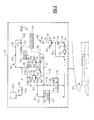
- FIG 2 illustrates a thermal management system 100 for a gas turbine engine, such as the gas turbine engine 20 illustrated by Figure 1 .
- the thermal management system 100 can manage the heat generated by the gas turbine engine 20 during its operation.
- the thermal management system 100 can communicate conditioned fluids to various engine systems of the gas turbine engine 20 to minimize this heat generation and dissipate the heat.
- the thermal management system 100 can simultaneously deliver conditioned fluids having different temperatures to both low temperature systems and high temperature systems of the gas turbine engine 20, as is further discussed below.
- the term "conditioned fluid" is intended to include heated, cooled and/or pressurized fluids. Of course, this view is highly schematic and is not necessarily shown to the scale it would be in practice.
- the thermal management system 100 is mounted to the gas turbine engine 20.
- the mounting location of the thermal management system 100 is application specific.
- Non-limiting example mounting location for the thermal management system 100 include the engine static structure 36 (see Figure 1 ), a core compartment, a fan compartment, a bypass fan passage and other locations.
- the thermal management system 100 includes a first fluid circuit 60 and a second fluid circuit 62.
- the first fluid circuit 60 can circulate a first fluid 81, such as engine oil
- the second fluid circuit 62 can circulate a second fluid 87, such as engine fuel.
- first fluid circuit 60 and the second fluid circuit 62 transfer heat between the fluids communicated through the separate circuits 60, 62 to manage the temperatures of these fluids, as is further discussed below.
- the first fluid circuit 60 incorporates a fluid tank 64, a first heat exchanger 66, a second heat exchanger 68, a third heat exchanger 70 and a pump 72.
- the pump 72 pumps a first fluid (indicated by arrow 81), such as oil, from the fluid tank 64 along a passage 74 to an inlet 76 of the first heat exchanger 66.
- the first fluid circuit 60 can include a filter 78 for filtering the first fluid 81 prior to communicating the first fluid 81 to the inlet 76.
- the first fluid circuit 60 can include a trim passage 80 for returning a portion of the first fluid 81 to the fluid tank 64 in the event an excess amount of the first fluid 81 is pumped from the fluid tank 64.
- the first fluid 81 is communicated through the first heat exchanger 66 and exchanges heat with a different fluid 82, such as air, to condition the first fluid 81.
- a different fluid 82 such as air
- the first heat exchanger 66 is an air/oil cooler that exchanges heat between oil and air.
- Heat from the first fluid 81 is transferred into the fluid 82 to provide a first conditioned fluid 83 that exits an outlet 84 of the first heat exchanger 66.
- the first conditioned fluid 83 is communicated along a passage 86 to a valve 88.
- the valve 88 controls the amount of the first conditioned fluid 83 that is communicated to the second heat exchanger 68 and the third heat exchanger 70.
- the second heat exchanger 68 either receives an entirety of the first conditioned fluid 83 that is received by the valve 88, or receives only a portion thereof, as is further detailed below.
- the first and second heat exchangers 66, 68 are in continuous operation during operation of the thermal management system 100, but the third heat exchanger 70 is only selectively operated as required.
- a first portion 85 of the first conditioned fluid 83 is communicated to an inlet 92 of the second heat exchanger 68 along a passage 90.
- the first portion 85 of the first conditioned fluid 83 is communicated through the second heat exchanger 68 and exchanges heat with the second fluid 87, such as fuel, that is circulated through the second fluid circuit 62.
- the second heat exchanger 68 renders a second conditioned fluid 89 which is communicated through an outlet 94 of the second heat exchanger 68 and into a passage 96.
- a second portion 91 of the first conditioned fluid 83 can be communicated along a passage 98 to an inlet 102 of the third heat exchanger 70.
- the second portion 91 of the first conditioned fluid 83 is communicated through the third heat exchanger 70 and exchanges heat with yet another fluid 104, such as air, to render a third conditioned fluid 93 that exits the third heat exchanger 70 at outlet 106.
- the third conditioned fluid 93 from the third heat exchanger 70 is communicated along a passage 108 and is eventually communicated into the passage 96 such that the second conditioned fluid 89 from the second heat exchanger 68 and the third conditioned fluid 93 from the third heat exchanger 70 are mixed together to render a mixed conditioned fluid 95.
- a first portion 97 of the mixed conditioned fluid 95 is communicated to a first engine system 110 along a passage 112.
- a second portion 99 of the mixed conditioned fluid 95 is communicated along passage 114 and is mixed with a third portion 101 of the first conditioned fluid 83 (communicated from the first heat exchanger 66 along a bypass passage 116 that extends between the first heat exchanger 66 and a second engine system 118) and is communicated to a second engine system 118.
- the second portion 99 of the mixed conditioned fluid 95 can include a greater temperature than the first portion 97 of the mixed conditioned fluid 95 because it is mixed with the hotter third portion 101 of the first conditioned fluid 83.
- the first engine system 110 could include a portion of the geared architecture 48 of the fan section 22, such as journal bearings or other parts of the geared architecture 48.
- the second engine system 118 could include an engine bearing compartment, an engine gearbox or a drive mechanism of the geared architecture 48. Although only two engine systems are illustrated, it should be understood that additional or fewer engine systems can receive conditioned fluids from the thermal management system 100.
- the second fluid circuit 62 of the thermal management system 100 includes a fluid tank 120, the second heat exchanger 68 (which is also incorporated into the first fluid circuit 60) and a pump 122.
- the second fluid circuit 62 can also optionally include a secondary pump 136.
- the fluid tank 120 stores a second fluid 87 that is different from the first fluid 81 for use by the gas turbine engine 20.
- the second fluid 87 is fuel.
- the pump 122 pumps the second fluid 87 from the fluid tank 120 along a passage 124 and through the second heat exchanger 68 along a passage 126 to extract heat from the first portion 85 of the first conditioned fluid 83 that is communicated through the second heat exchanger 68 in the first fluid circuit 60.
- a conditioned second fluid 105 is delivered along a passage 128 to a portion of the gas turbine engine, such as the combustor section 26 for generating the hot combustion gases that flow to the turbine section 28.
- a portion 107 of the conditioned second fluid 105 is returned to the passage 124 via a bypass passage 130.
- the second fluid circuit 62 can also incorporate a sensor 132, such as a temperature sensor or other suitable sensor.
- the sensor 132 monitors the temperature of the conditioned second fluid 105.
- the sensor 132 communicates with an engine controller 134.
- the engine controller 134 is programed with the necessary logic to interpret the information from the sensor 132, among other information, and modulate a positioning of the valve 88.
- the position of the valve 88 establishes what amount, if any, of the first conditioned fluid 83 will be communicated to the second and third heat exchangers 68, 70. In other words, the position of the valve 88 controls the amount of heat added to the second fluid 87 at different engine power conditions.
- Other valves, sensors and controls although not shown, could also be incorporated into the thermal management system 100.
- the third heat exchanger 70 receives a portion of the first conditioned fluid 83 only if a temperature of the conditioned second fluid 105 of the second fluid circuit 62 is above a predefined threshold.
- the predefined threshold is approximately 300° F/148.9 ° C, although the actual setting will depend on design specific parameters. If the sensor 132 alerts the engine controller 134 (via a signal, for example) that this predefined threshold has been exceeded, the controller 134 modulates the valve 88 to split a flow of the first conditioned fluid 83 between the second heat exchanger 68 and the third heat exchanger 70.
Landscapes
- Engineering & Computer Science (AREA)
- Chemical & Material Sciences (AREA)
- Combustion & Propulsion (AREA)
- Mechanical Engineering (AREA)
- General Engineering & Computer Science (AREA)
- Engine Equipment That Uses Special Cycles (AREA)
Abstract
Description
- This disclosure relates generally to a gas turbine engine, and more particularly to a gas turbine engine thermal management system that manages the heat generated by a gas turbine engine.
- Gas turbine engines, such as turbofan gas turbine engines, generally include a fan section, a compressor section, a combustor section and a turbine section. During operation, airflow is pressurized in the compressor section and is mixed with fuel and burned in the combustor section. The hot combustion gases that are generated in the combustor section are communicated through the turbine section. The turbine section extracts energy from the hot combustion gases to power the compressor section, the fan section and other gas turbine engine loads.
- A thermal management system can be employed within the gas turbine engine to manage the heat generated by the gas turbine engine. Thermal management systems maintain operable temperatures for the engine fuel, oil and other fluids that are communicated throughout the engine. For example, a portion of the heat of the engine oil can be transferred into the engine fuel to increase the efficiency of the gas turbine engine.
- A thermal management system for a gas turbine engine includes a first heat exchanger that provides a first conditioned fluid, a second heat exchanger in series flow communication with the first heat exchanger and that exchanges heat with the first conditioned fluid to provide a second conditioned fluid, and a third heat exchanger in parallel flow communication with the second heat exchanger and that selectively exchanges heat with the first conditioned fluid to provide a third conditioned fluid. The second conditioned fluid and the third conditioned fluid combine to provide a mixed conditioned fluid. A first portion of the mixed conditioned fluid including a first temperature is communicated to a first engine system. A second portion of the mixed conditioned fluid including a second temperature is communicated to a second engine system. The second temperature includes a greater temperature than the first temperature.
- This aspect of the present invention also extends to a gas turbine engine comprising the thermal management system.
- In another exemplary embodiment, a gas turbine engine includes a compressor section, a combustor section and a turbine section. The gas turbine engine includes a thermal management system incorporating a first fluid circuit and a second fluid circuit. The thermal management system manages heat generated in at least one of the compressor section, the combustor section and the turbine section. The first fluid circuit of the thermal management system selectively communicates a first portion of a conditioned fluid having a first temperature to a first engine system and a second portion of the conditioned fluid having a second temperature to a second engine system. The second temperature is a greater temperature than the first temperature.
- In yet another exemplary embodiment, a method of managing heat generated during operation of a gas turbine engine with a thermal management system includes communicating a first portion of a conditioned fluid having a first temperature to a first engine system and communicating a second portion of the conditioned fluid having a second temperature to a second engine system. The second temperature is a greater temperature than the first temperature.
- The various features and advantages of this disclosure will become apparent to those skilled in the art from the following detailed description. The drawings that accompany the detailed description can be briefly described as follows.
-
-
Figure 1 schematically illustrates a gas turbine engine. -
Figure 2 illustrates an exemplary thermal management system for a gas turbine engine. -
Figure 1 schematically illustrates agas turbine engine 20. The examplegas turbine engine 20 is a two-spool turbofan engine that generally incorporates afan section 22, acompressor section 24, acombustor section 26 and aturbine section 28. Alternative engines might include fewer or additional sections such as an augmenter section (not shown) among other systems or features. Generally, thefan section 22 drives air along a bypass flow path, while thecompressor section 24 drives air along a core flow path for compression and communication into thecombustor section 26. The hot combustion gases generated in thecombustor section 26 are expanded by theturbine section 28. This view is highly schematic and is included to provide a basic understanding of thegas turbine engine 20 and not to limit the disclosure. This disclosure extends to all types of gas turbine engines and for all types of applications, including but not limited to turbofan, turbojet and turboprop engines. - The
gas turbine engine 20 generally includes at least alow speed spool 30 and ahigh speed spool 32 mounted for rotation about an engine centerline axis A relative to an enginestatic structure 36 viaseveral bearing systems 38. Thelow speed spool 30 generally includes aninner shaft 40 that interconnects afan 42, alow pressure compressor 44 and alow pressure turbine 46. Theinner shaft 40 can connect to thefan 42 through a gearedarchitecture 48 to drive thefan 42 at a lower speed than thelow speed spool 30. Although shown schematically, the gearedarchitecture 48 can include a multitude of parts including but not limited to bearings, gears and drive mechanisms. Thehigh speed spool 32 includes anouter shaft 50 that interconnects thehigh pressure compressor 52 and ahigh pressure turbine 54. - A
combustor 56 is arranged between thehigh pressure compressor 52 and thehigh pressure turbine 54. Theinner shaft 40 and theouter shaft 50 are concentric and rotate about the engine centerline axis A. A core airflow is compressed by thelow pressure compressor 44 and thehigh pressure compressor 52, is mixed with fuel and burned within thecombustor 56, and is then expanded over thehigh pressure turbine 54 and thelow pressure turbine 46. Theturbines low speed spool 30 and thehigh speed spool 32 in response to the expansion. - Multiple sections of the
gas turbine engine 20 generate heat during engine operation, including thefan section 22, thecompressor section 24, thecombustor section 26 and theturbine section 28. This heat may be carried by fluids that are communicated throughout these and other various sections of thegas turbine engine 20. For example, engine fuel and engine oil are circulated throughout thegas turbine engine 20 and carry a portion of the heat that is generated during engine operation. In this disclosure, the term "fluid" is intended to include fuel, oil, lubricating fluids, hydraulic fluids or any other fluids circulated through thegas turbine engine 20. -
Figure 2 illustrates athermal management system 100 for a gas turbine engine, such as thegas turbine engine 20 illustrated byFigure 1 . Thethermal management system 100 can manage the heat generated by thegas turbine engine 20 during its operation. Thethermal management system 100 can communicate conditioned fluids to various engine systems of thegas turbine engine 20 to minimize this heat generation and dissipate the heat. For example, thethermal management system 100 can simultaneously deliver conditioned fluids having different temperatures to both low temperature systems and high temperature systems of thegas turbine engine 20, as is further discussed below. In this disclosure, the term "conditioned fluid" is intended to include heated, cooled and/or pressurized fluids. Of course, this view is highly schematic and is not necessarily shown to the scale it would be in practice. - The
thermal management system 100 is mounted to thegas turbine engine 20. The mounting location of thethermal management system 100 is application specific. Non-limiting example mounting location for thethermal management system 100 include the engine static structure 36 (seeFigure 1 ), a core compartment, a fan compartment, a bypass fan passage and other locations. - The
thermal management system 100 includes afirst fluid circuit 60 and asecond fluid circuit 62. For example, thefirst fluid circuit 60 can circulate afirst fluid 81, such as engine oil, and thesecond fluid circuit 62 can circulate asecond fluid 87, such as engine fuel. It should be understood that other fluids in addition to oil and fuel are contemplated as within the scope of this disclosure. In combination, thefirst fluid circuit 60 and thesecond fluid circuit 62 transfer heat between the fluids communicated through theseparate circuits - The
first fluid circuit 60 incorporates afluid tank 64, afirst heat exchanger 66, asecond heat exchanger 68, athird heat exchanger 70 and apump 72. Thepump 72 pumps a first fluid (indicated by arrow 81), such as oil, from thefluid tank 64 along apassage 74 to aninlet 76 of thefirst heat exchanger 66. Optionally, thefirst fluid circuit 60 can include afilter 78 for filtering thefirst fluid 81 prior to communicating thefirst fluid 81 to theinlet 76. Additionally, thefirst fluid circuit 60 can include atrim passage 80 for returning a portion of thefirst fluid 81 to thefluid tank 64 in the event an excess amount of thefirst fluid 81 is pumped from thefluid tank 64. - The
first fluid 81 is communicated through thefirst heat exchanger 66 and exchanges heat with adifferent fluid 82, such as air, to condition thefirst fluid 81. In this example, thefirst heat exchanger 66 is an air/oil cooler that exchanges heat between oil and air. However, other types of heat exchangers can also be utilized. Heat from thefirst fluid 81 is transferred into the fluid 82 to provide a first conditionedfluid 83 that exits anoutlet 84 of thefirst heat exchanger 66. - The first conditioned
fluid 83 is communicated along apassage 86 to avalve 88. Thevalve 88 controls the amount of the first conditionedfluid 83 that is communicated to thesecond heat exchanger 68 and thethird heat exchanger 70. Thesecond heat exchanger 68 either receives an entirety of the first conditionedfluid 83 that is received by thevalve 88, or receives only a portion thereof, as is further detailed below. In other words, the first andsecond heat exchangers thermal management system 100, but thethird heat exchanger 70 is only selectively operated as required. - A
first portion 85 of the first conditionedfluid 83 is communicated to aninlet 92 of thesecond heat exchanger 68 along apassage 90. Thefirst portion 85 of the first conditionedfluid 83 is communicated through thesecond heat exchanger 68 and exchanges heat with thesecond fluid 87, such as fuel, that is circulated through thesecond fluid circuit 62. Thesecond heat exchanger 68 renders a second conditionedfluid 89 which is communicated through anoutlet 94 of thesecond heat exchanger 68 and into apassage 96. - To the extent the
third heat exchanger 70 receives a portion of the first conditioned fluid 83 (discussed in greater detail below), asecond portion 91 of the first conditionedfluid 83 can be communicated along apassage 98 to an inlet 102 of thethird heat exchanger 70. Thesecond portion 91 of the first conditionedfluid 83 is communicated through thethird heat exchanger 70 and exchanges heat with yet another fluid 104, such as air, to render a thirdconditioned fluid 93 that exits thethird heat exchanger 70 atoutlet 106. The third conditioned fluid 93 from thethird heat exchanger 70 is communicated along apassage 108 and is eventually communicated into thepassage 96 such that the second conditionedfluid 89 from thesecond heat exchanger 68 and the third conditioned fluid 93 from thethird heat exchanger 70 are mixed together to render a mixed conditionedfluid 95. - A
first portion 97 of the mixed conditionedfluid 95 is communicated to afirst engine system 110 along apassage 112. Asecond portion 99 of the mixed conditionedfluid 95 is communicated alongpassage 114 and is mixed with a third portion 101 of the first conditioned fluid 83 (communicated from thefirst heat exchanger 66 along abypass passage 116 that extends between thefirst heat exchanger 66 and a second engine system 118) and is communicated to asecond engine system 118. In this way, conditioned fluids having varying temperatures can be delivered to separate engine systems. For example, thesecond portion 99 of the mixed conditionedfluid 95 can include a greater temperature than thefirst portion 97 of the mixed conditionedfluid 95 because it is mixed with the hotter third portion 101 of the first conditionedfluid 83. - The
first engine system 110 could include a portion of the gearedarchitecture 48 of thefan section 22, such as journal bearings or other parts of the gearedarchitecture 48. Thesecond engine system 118 could include an engine bearing compartment, an engine gearbox or a drive mechanism of the gearedarchitecture 48. Although only two engine systems are illustrated, it should be understood that additional or fewer engine systems can receive conditioned fluids from thethermal management system 100. - The
second fluid circuit 62 of thethermal management system 100 includes afluid tank 120, the second heat exchanger 68 (which is also incorporated into the first fluid circuit 60) and apump 122. Thesecond fluid circuit 62 can also optionally include asecondary pump 136. - The
fluid tank 120 stores asecond fluid 87 that is different from thefirst fluid 81 for use by thegas turbine engine 20. In one example, thesecond fluid 87 is fuel. Thepump 122 pumps the second fluid 87 from thefluid tank 120 along apassage 124 and through thesecond heat exchanger 68 along apassage 126 to extract heat from thefirst portion 85 of the first conditionedfluid 83 that is communicated through thesecond heat exchanger 68 in thefirst fluid circuit 60. A conditionedsecond fluid 105 is delivered along apassage 128 to a portion of the gas turbine engine, such as thecombustor section 26 for generating the hot combustion gases that flow to theturbine section 28. Aportion 107 of the conditionedsecond fluid 105 is returned to thepassage 124 via abypass passage 130. - The
second fluid circuit 62 can also incorporate asensor 132, such as a temperature sensor or other suitable sensor. Thesensor 132 monitors the temperature of the conditionedsecond fluid 105. Thesensor 132 communicates with anengine controller 134. Theengine controller 134 is programed with the necessary logic to interpret the information from thesensor 132, among other information, and modulate a positioning of thevalve 88. The position of thevalve 88 establishes what amount, if any, of the first conditionedfluid 83 will be communicated to the second andthird heat exchangers valve 88 controls the amount of heat added to thesecond fluid 87 at different engine power conditions. Other valves, sensors and controls, although not shown, could also be incorporated into thethermal management system 100. - In one example, the
third heat exchanger 70 receives a portion of the first conditionedfluid 83 only if a temperature of the conditionedsecond fluid 105 of thesecond fluid circuit 62 is above a predefined threshold. In one example, the predefined threshold is approximately 300° F/148.9 ° C, although the actual setting will depend on design specific parameters. If thesensor 132 alerts the engine controller 134 (via a signal, for example) that this predefined threshold has been exceeded, thecontroller 134 modulates thevalve 88 to split a flow of the first conditionedfluid 83 between thesecond heat exchanger 68 and thethird heat exchanger 70. Of course, other parameters can also be monitored and interpreted by theengine controller 134 in addition to the temperature fromsensor 132, and other predefined thresholds can be set for controlling thevalve 88. The actual amount of the first conditionedfluid 83 that is communicated to each of the second andthird heat exchangers controller 134. - The foregoing description shall be interpreted as illustrative and not in any limiting sense. A worker of ordinary skill in the art would understand that certain modifications could come within the scope of this disclosure. For these reasons, the following claims should be studied to determine the true scope and content of this disclosure.
Claims (15)
- A thermal management system (100) for a gas turbine engine (20), comprising:a first heat exchanger (66) that provides a first conditioned fluid (83);a second heat exchanger (68) in series flow communication with said first heat exchanger (66) and that exchanges heat with at least a portion (85) of said first conditioned fluid (83) to provide a second conditioned fluid (89);a third heat exchanger (70) in parallel flow communication with said second heat exchanger (68) and that selectively exchanges heat with a portion (91) of said first conditioned fluid (83) to provide a third conditioned fluid (93), wherein said second conditioned fluid (68) and said third conditioned fluid (93) combine to provide a mixed conditioned fluid (95); andwherein a first portion (97) of said mixed conditioned fluid (95) having a first temperature is communicated to a first engine system (110) and a second portion (99) of said mixed conditioned fluid (95) having a second temperature is communicated to a second engine system (118), wherein said second temperature includes a greater temperature than said first temperature.
- The system (100) as recited in claim 1, wherein said first heat exchanger (66) and said third heat exchanger (70) are air/oil heat exchangers and said second heat exchanger (68) is a fuel/oil heat exchanger.
- The system (100) as recited in claim 1 or 2, comprising a valve (88) that selectively modulates to split a flow of said first conditioned fluid (83) between said second heat exchanger (68) and said third heat exchanger (70).
- The system (100) as recited in claim 3, comprising a sensor (132) that communicates with a controller (134) to selectively control a position of said valve (88), and optionally wherein said controller (134) modulates said valve (88) to communicate a portion (91) of said first conditioned fluid (83) to said third heat exchanger (70) in response to said sensor (132) sensing that a predefined threshold has been exceeded.
- The system (100) as recited in any preceding claim, wherein said second heat exchanger (68) receives a first portion (83) of said first conditioned fluid (83) and said third heat exchanger (70) receives a second portion (91) of said first conditioned fluid (83).
- The system (100) as recited in any preceding claim, wherein said first heat exchanger (66), said second heat exchanger (68) and said third heat exchanger (70) are incorporated into a first fluid circuit (60) of the thermal management system (100) and said second heat exchanger (68) is incorporated into a second fluid circuit (62) of the thermal management system (100).
- A gas turbine engine (20), comprising:a compressor section (24), a combustor section (26) and a turbine section (28);a thermal management system (100) that incorporates a first fluid circuit (60) and a second fluid circuit (62) that manage heat generated in at least a portion of the gas turbine engine (20); andwherein said first fluid circuit (60) of said thermal management system selectively communicates a first portion (97) of a conditioned fluid (95) having a first temperature to a first engine system (100) and a second portion (99) of said conditioned fluid (95) having a second temperature to a second engine system (118), wherein said second temperature is a greater temperature than said first temperature.
- The gas turbine engine (20) as recited in claim 7, wherein said first fluid circuit (60) circulates oil.
- The gas turbine engine (20) as recited in claim 7 or 8, wherein said second fluid circuit (62) circulates fuel.
- The gas turbine engine (20) as recited in any of claims 7 to 9, wherein said first fluid circuit (60) incorporates a first heat exchanger (66), a second heat exchanger (68) and a third heat exchanger (70) and said second fluid circuit (62) incorporates said second heat exchanger (68), and optionally comprises a bypass passage (116) extending between said first heat exchanger (66) and said second engine system (118).
- The gas turbine engine (20) as recited in any of claims 7 to 10, wherein said second fluid circuit (62) of said thermal management system (100) communicates a conditioned second fluid (105), optionally to at least said combustor section (26).
- The gas turbine engine (20) as recited in claim 11, comprising a sensor (132) that senses a temperature of said conditioned second fluid (105) and a controller (134) in communication with said sensor (132) and operable to modulate a valve (88) where said temperature of said conditioned second fluid (105) exceeds a predefined threshold.
- The system (100) or gas turbine engine (20) as recited in any preceding claim, wherein:said first engine system (110) includes a portion of a geared architecture (48) of said gas turbine engine (20); and/orsaid second engine system (118) includes at least one of an engine bearing compartment, an engine gearbox and a drive mechanism of a geared architecture (48) of the gas turbine engine (20).
- A method of managing heat generated during operation of the gas turbine engine as recited in any of claims 7 to 13 with the thermal management system (100), comprising the steps of:communicating the first portion (97) of the conditioned fluid (95) having the first temperature to the first engine system (110); andcommunicating the second portion (99) of the conditioned fluid (95) having the second temperature to the second engine system (118).
- The method as recited in claim 14, wherein the thermal management system (100) includes a first heat exchanger (66), a second heat exchanger (68) and a third heat exchanger (70), and comprising the steps of:sensing a temperature of a fluid (105) communicated from the second heat exchanger (68); andmodulating a valve (88) to control an amount of heat added to the fluid (105) in response to the sensed temperature exceeding a predefined threshold, and optionally:communicating a conditioned fluid (83) to the third heat exchanger (70) in response to the temperature of the fluid (105) exceeding the predefined threshold; and/ormixing the second portion (99) of the conditioned fluid (83) with another fluid (101) to increase the second temperature.
Applications Claiming Priority (1)
| Application Number | Priority Date | Filing Date | Title |
|---|---|---|---|
| US13/285,454 US8495857B2 (en) | 2011-10-31 | 2011-10-31 | Gas turbine engine thermal management system |
Publications (3)
| Publication Number | Publication Date |
|---|---|
| EP2587024A2 true EP2587024A2 (en) | 2013-05-01 |
| EP2587024A3 EP2587024A3 (en) | 2017-01-18 |
| EP2587024B1 EP2587024B1 (en) | 2020-02-05 |
Family
ID=47172379
Family Applications (1)
| Application Number | Title | Priority Date | Filing Date |
|---|---|---|---|
| EP12189781.3A Active EP2587024B1 (en) | 2011-10-31 | 2012-10-24 | Gas turbine engine thermal management system |
Country Status (3)
| Country | Link |
|---|---|
| US (2) | US8495857B2 (en) |
| EP (1) | EP2587024B1 (en) |
| CN (1) | CN103089446B (en) |
Cited By (5)
| Publication number | Priority date | Publication date | Assignee | Title |
|---|---|---|---|---|
| WO2013154637A1 (en) | 2012-01-31 | 2013-10-17 | United Technologies Corporation | Gas turbine engine with geared turbofan and oil thermal management system |
| EP3260668A1 (en) * | 2016-06-20 | 2017-12-27 | United Technologies Corporation | Lubrication system with multiple lubrication circuits |
| EP3736469A1 (en) * | 2019-05-10 | 2020-11-11 | Siemens Gamesa Renewable Energy A/S | Lubrication system for a gearbox and wind turbine |
| FR3110937A1 (en) * | 2020-05-28 | 2021-12-03 | Safran | Installation for supplying cryogenic fuel to the combustion chamber of a turbomachine. |
| CN119737231A (en) * | 2025-03-07 | 2025-04-01 | 南京航空航天大学 | A variable topology fuel and lubricant self-matching thermal management system for aircraft engines |
Families Citing this family (15)
| Publication number | Priority date | Publication date | Assignee | Title |
|---|---|---|---|---|
| FR2979671B1 (en) * | 2011-09-07 | 2017-02-10 | Snecma | OIL AND FUEL CIRCUITS IN A TURBOMACHINE |
| US9022176B2 (en) * | 2011-10-14 | 2015-05-05 | Gm Global Technology Operations, Llc | Temperature management system for transmission |
| WO2014182519A2 (en) * | 2013-05-10 | 2014-11-13 | United Technologies Corporation | Inlet door control for startup of gas turbine engine |
| WO2015047885A1 (en) | 2013-09-26 | 2015-04-02 | United Technologies Corporation | Controlling lubricant flow in epicyclic gearbox |
| US10215097B2 (en) * | 2015-12-08 | 2019-02-26 | General Electric Company | Thermal management system |
| US10823066B2 (en) * | 2015-12-09 | 2020-11-03 | General Electric Company | Thermal management system |
| US10247296B2 (en) * | 2016-12-12 | 2019-04-02 | General Electric Company | Additively manufactured gearbox with integral heat exchanger |
| US10294873B2 (en) * | 2017-01-31 | 2019-05-21 | United Technologies Corporation | Aircraft bleed system |
| US11174789B2 (en) * | 2018-05-23 | 2021-11-16 | General Electric Company | Air cycle assembly for a gas turbine engine assembly |
| US11668289B2 (en) | 2021-05-12 | 2023-06-06 | Yantai Jereh Petroleum Equipment & Technologies Co., Ltd. | Fracturing apparatus |
| US12442370B2 (en) | 2021-04-07 | 2025-10-14 | Yantai Jereh Petroleum Equipment & Technologies Co., Ltd. | Fracturing equipment having multiple electric-power supplies |
| EP4386193B1 (en) | 2022-12-16 | 2025-01-01 | Rolls-Royce plc | Thermal management system for gas turbine engine |
| GB202319119D0 (en) * | 2023-12-14 | 2024-01-31 | Rolls Royce Plc | Fuel characteristic |
| GB202319125D0 (en) * | 2023-12-14 | 2024-01-31 | Rolls Royce Plc | Operating a gas turbine engine |
| US20260062135A1 (en) * | 2024-09-03 | 2026-03-05 | Honeywell International Inc. | Vehicle thermal management system |
Family Cites Families (16)
| Publication number | Priority date | Publication date | Assignee | Title |
|---|---|---|---|---|
| US4020632A (en) * | 1975-07-17 | 1977-05-03 | The United States Of America As Represented By The United States National Aeronautics And Space Administration Office Of General Counsel-Code Gp | Oil cooling system for a gas turbine engine |
| GB2095756B (en) * | 1982-03-05 | 1985-01-16 | United Technologies Corp | Balancing the heat flow between components associated with a gas turbine engine |
| US4696156A (en) * | 1986-06-03 | 1987-09-29 | United Technologies Corporation | Fuel and oil heat management system for a gas turbine engine |
| US6415595B1 (en) * | 2000-08-22 | 2002-07-09 | Hamilton Sundstrand Corporation | Integrated thermal management and coolant system for an aircraft |
| US7260926B2 (en) * | 2004-01-20 | 2007-08-28 | United Technologies Corporation | Thermal management system for an aircraft |
| JP2006017039A (en) * | 2004-07-02 | 2006-01-19 | Hitachi Engineering & Services Co Ltd | Gas turbine and its lubricating oil cooling method |
| EA010047B1 (en) * | 2004-12-20 | 2008-06-30 | Флуор Текнолоджиз Корпорейшн | Configurations and methods for lng fueled power plants |
| US7765788B2 (en) * | 2006-07-06 | 2010-08-03 | United Technologies Corporation | Cooling exchanger duct |
| US7908840B2 (en) * | 2006-11-29 | 2011-03-22 | United Technologies Corporation | Turbine engine with integrated generator having shared lubrication system |
| US7836680B2 (en) | 2007-06-20 | 2010-11-23 | United Technologies Corporation | Aircraft combination engines thermal management system |
| US20090313999A1 (en) | 2008-05-13 | 2009-12-24 | Scott Hunter | Method and apparatus for controlling fuel in a gas turbine engine |
| US7984606B2 (en) | 2008-11-03 | 2011-07-26 | Propulsion, Gas Turbine, And Energy Evaluations, Llc | Systems and methods for thermal management in a gas turbine powerplant |
| US8997449B2 (en) * | 2008-12-22 | 2015-04-07 | Pratt & Whitney Canada Corp. | Flow restrictor for lubrication line |
| US7997062B2 (en) * | 2009-01-29 | 2011-08-16 | Pratt & Whitney Canada Corp. | Dual channel regulated fuel-oil heat exchanger |
| US8438850B2 (en) * | 2009-02-17 | 2013-05-14 | General Electric Company | Waste heat utilization for pre-heating fuel |
| US20110023491A1 (en) | 2009-07-30 | 2011-02-03 | General Electric Company | System and method for supplying fuel to a gas turbine |
-
2011
- 2011-10-31 US US13/285,454 patent/US8495857B2/en active Active
-
2012
- 2012-10-24 EP EP12189781.3A patent/EP2587024B1/en active Active
- 2012-10-31 CN CN201210425927.0A patent/CN103089446B/en active Active
-
2013
- 2013-06-25 US US13/926,154 patent/US20130284398A1/en not_active Abandoned
Non-Patent Citations (1)
| Title |
|---|
| None |
Cited By (10)
| Publication number | Priority date | Publication date | Assignee | Title |
|---|---|---|---|---|
| WO2013154637A1 (en) | 2012-01-31 | 2013-10-17 | United Technologies Corporation | Gas turbine engine with geared turbofan and oil thermal management system |
| EP2809915A4 (en) * | 2012-01-31 | 2015-10-14 | United Technologies Corp | GAS TURBINE ENGINE COMPRISING A GEAR DOUBLE FLOW TURBOREACTOR AND A THERMAL OIL MANAGEMENT SYSTEM |
| US9879563B2 (en) | 2012-01-31 | 2018-01-30 | United Technologies Corporation | Gas turbine engine with geared turbofan and oil thermal management system |
| EP3260668A1 (en) * | 2016-06-20 | 2017-12-27 | United Technologies Corporation | Lubrication system with multiple lubrication circuits |
| EP3736469A1 (en) * | 2019-05-10 | 2020-11-11 | Siemens Gamesa Renewable Energy A/S | Lubrication system for a gearbox and wind turbine |
| FR3110937A1 (en) * | 2020-05-28 | 2021-12-03 | Safran | Installation for supplying cryogenic fuel to the combustion chamber of a turbomachine. |
| WO2021240114A3 (en) * | 2020-05-28 | 2022-02-10 | Safran | Installation for supplying cryogenic fuel to the combustion chamber of a turbomachine |
| US11846234B2 (en) | 2020-05-28 | 2023-12-19 | Safran | Installation for supplying cryogenic fuel to the combustion chamber of a turbine engine |
| CN119737231A (en) * | 2025-03-07 | 2025-04-01 | 南京航空航天大学 | A variable topology fuel and lubricant self-matching thermal management system for aircraft engines |
| CN119737231B (en) * | 2025-03-07 | 2025-10-17 | 南京航空航天大学 | A variable topology fuel and oil self-matching thermal management system for aircraft engines |
Also Published As
| Publication number | Publication date |
|---|---|
| EP2587024B1 (en) | 2020-02-05 |
| US8495857B2 (en) | 2013-07-30 |
| CN103089446B (en) | 2015-06-17 |
| US20130104559A1 (en) | 2013-05-02 |
| EP2587024A3 (en) | 2017-01-18 |
| CN103089446A (en) | 2013-05-08 |
| US20130284398A1 (en) | 2013-10-31 |
Similar Documents
| Publication | Publication Date | Title |
|---|---|---|
| EP2587024B1 (en) | Gas turbine engine thermal management system | |
| US9334802B2 (en) | Gas turbine engine thermal management system | |
| EP3730763B1 (en) | Dynamic thermal load monitoring and mitigation for aircraft systems | |
| EP3726027B1 (en) | Integrated thermal management system for fuel cooling | |
| US11035250B2 (en) | Gas turbine engine fluid cooling systems and methods of assembling the same | |
| EP3726028B1 (en) | Multiple stream heat exchanger | |
| EP3246531B1 (en) | Oil coking mitigation in a gas turbine engine | |
| EP2546472B1 (en) | Thermal management system for gas turbine engine | |
| US20090313999A1 (en) | Method and apparatus for controlling fuel in a gas turbine engine | |
| EP3067534B1 (en) | Gas turbine engine fuel-oil heat exchange system | |
| EP2809910B1 (en) | Gas turbine engine buffer system | |
| WO2013154630A1 (en) | Gas turbine engine buffer system | |
| US20130036722A1 (en) | Fuel system having fuel control unit and heat exchanger | |
| CN115853647A (en) | Systems and methods for detecting airflow failure conditions | |
| EP4130442B1 (en) | Lubrication system for a turbine engine | |
| EP4116546B1 (en) | Lubrication system with anti-priming feature | |
| EP2565392A2 (en) | Gas turbine engine air cycle system | |
| US20170058779A1 (en) | Engine lubrication system using de-oxygenated fuel | |
| CN115853646A (en) | System and method for regulating heat transfer bus pressure | |
| EP2971646B1 (en) | Gas turbine engine thermal management system |
Legal Events
| Date | Code | Title | Description |
|---|---|---|---|
| PUAI | Public reference made under article 153(3) epc to a published international application that has entered the european phase |
Free format text: ORIGINAL CODE: 0009012 |
|
| AK | Designated contracting states |
Kind code of ref document: A2 Designated state(s): AL AT BE BG CH CY CZ DE DK EE ES FI FR GB GR HR HU IE IS IT LI LT LU LV MC MK MT NL NO PL PT RO RS SE SI SK SM TR |
|
| AX | Request for extension of the european patent |
Extension state: BA ME |
|
| RAP1 | Party data changed (applicant data changed or rights of an application transferred) |
Owner name: UNITED TECHNOLOGIES CORPORATION |
|
| PUAL | Search report despatched |
Free format text: ORIGINAL CODE: 0009013 |
|
| AK | Designated contracting states |
Kind code of ref document: A3 Designated state(s): AL AT BE BG CH CY CZ DE DK EE ES FI FR GB GR HR HU IE IS IT LI LT LU LV MC MK MT NL NO PL PT RO RS SE SI SK SM TR |
|
| AX | Request for extension of the european patent |
Extension state: BA ME |
|
| RIC1 | Information provided on ipc code assigned before grant |
Ipc: F02C 7/18 20060101ALI20161214BHEP Ipc: F02C 7/08 20060101AFI20161214BHEP Ipc: F02C 7/224 20060101ALI20161214BHEP |
|
| STAA | Information on the status of an ep patent application or granted ep patent |
Free format text: STATUS: REQUEST FOR EXAMINATION WAS MADE |
|
| 17P | Request for examination filed |
Effective date: 20170718 |
|
| RBV | Designated contracting states (corrected) |
Designated state(s): AL AT BE BG CH CY CZ DE DK EE ES FI FR GB GR HR HU IE IS IT LI LT LU LV MC MK MT NL NO PL PT RO RS SE SI SK SM TR |
|
| STAA | Information on the status of an ep patent application or granted ep patent |
Free format text: STATUS: EXAMINATION IS IN PROGRESS |
|
| 17Q | First examination report despatched |
Effective date: 20181214 |
|
| GRAP | Despatch of communication of intention to grant a patent |
Free format text: ORIGINAL CODE: EPIDOSNIGR1 |
|
| STAA | Information on the status of an ep patent application or granted ep patent |
Free format text: STATUS: GRANT OF PATENT IS INTENDED |
|
| INTG | Intention to grant announced |
Effective date: 20190802 |
|
| GRAS | Grant fee paid |
Free format text: ORIGINAL CODE: EPIDOSNIGR3 |
|
| GRAA | (expected) grant |
Free format text: ORIGINAL CODE: 0009210 |
|
| STAA | Information on the status of an ep patent application or granted ep patent |
Free format text: STATUS: THE PATENT HAS BEEN GRANTED |
|
| AK | Designated contracting states |
Kind code of ref document: B1 Designated state(s): AL AT BE BG CH CY CZ DE DK EE ES FI FR GB GR HR HU IE IS IT LI LT LU LV MC MK MT NL NO PL PT RO RS SE SI SK SM TR |
|
| REG | Reference to a national code |
Ref country code: GB Ref legal event code: FG4D |
|
| REG | Reference to a national code |
Ref country code: AT Ref legal event code: REF Ref document number: 1230060 Country of ref document: AT Kind code of ref document: T Effective date: 20200215 |
|
| REG | Reference to a national code |
Ref country code: DE Ref legal event code: R096 Ref document number: 602012067533 Country of ref document: DE |
|
| REG | Reference to a national code |
Ref country code: IE Ref legal event code: FG4D |
|
| REG | Reference to a national code |
Ref country code: CH Ref legal event code: EP |
|
| REG | Reference to a national code |
Ref country code: NL Ref legal event code: MP Effective date: 20200205 |
|
| PG25 | Lapsed in a contracting state [announced via postgrant information from national office to epo] |
Ref country code: RS Free format text: LAPSE BECAUSE OF FAILURE TO SUBMIT A TRANSLATION OF THE DESCRIPTION OR TO PAY THE FEE WITHIN THE PRESCRIBED TIME-LIMIT Effective date: 20200205 Ref country code: PT Free format text: LAPSE BECAUSE OF FAILURE TO SUBMIT A TRANSLATION OF THE DESCRIPTION OR TO PAY THE FEE WITHIN THE PRESCRIBED TIME-LIMIT Effective date: 20200628 Ref country code: NO Free format text: LAPSE BECAUSE OF FAILURE TO SUBMIT A TRANSLATION OF THE DESCRIPTION OR TO PAY THE FEE WITHIN THE PRESCRIBED TIME-LIMIT Effective date: 20200505 Ref country code: FI Free format text: LAPSE BECAUSE OF FAILURE TO SUBMIT A TRANSLATION OF THE DESCRIPTION OR TO PAY THE FEE WITHIN THE PRESCRIBED TIME-LIMIT Effective date: 20200205 |
|
| REG | Reference to a national code |
Ref country code: LT Ref legal event code: MG4D |
|
| PG25 | Lapsed in a contracting state [announced via postgrant information from national office to epo] |
Ref country code: SE Free format text: LAPSE BECAUSE OF FAILURE TO SUBMIT A TRANSLATION OF THE DESCRIPTION OR TO PAY THE FEE WITHIN THE PRESCRIBED TIME-LIMIT Effective date: 20200205 Ref country code: LV Free format text: LAPSE BECAUSE OF FAILURE TO SUBMIT A TRANSLATION OF THE DESCRIPTION OR TO PAY THE FEE WITHIN THE PRESCRIBED TIME-LIMIT Effective date: 20200205 Ref country code: HR Free format text: LAPSE BECAUSE OF FAILURE TO SUBMIT A TRANSLATION OF THE DESCRIPTION OR TO PAY THE FEE WITHIN THE PRESCRIBED TIME-LIMIT Effective date: 20200205 Ref country code: IS Free format text: LAPSE BECAUSE OF FAILURE TO SUBMIT A TRANSLATION OF THE DESCRIPTION OR TO PAY THE FEE WITHIN THE PRESCRIBED TIME-LIMIT Effective date: 20200605 Ref country code: GR Free format text: LAPSE BECAUSE OF FAILURE TO SUBMIT A TRANSLATION OF THE DESCRIPTION OR TO PAY THE FEE WITHIN THE PRESCRIBED TIME-LIMIT Effective date: 20200506 Ref country code: BG Free format text: LAPSE BECAUSE OF FAILURE TO SUBMIT A TRANSLATION OF THE DESCRIPTION OR TO PAY THE FEE WITHIN THE PRESCRIBED TIME-LIMIT Effective date: 20200505 |
|
| PG25 | Lapsed in a contracting state [announced via postgrant information from national office to epo] |
Ref country code: NL Free format text: LAPSE BECAUSE OF FAILURE TO SUBMIT A TRANSLATION OF THE DESCRIPTION OR TO PAY THE FEE WITHIN THE PRESCRIBED TIME-LIMIT Effective date: 20200205 |
|
| PG25 | Lapsed in a contracting state [announced via postgrant information from national office to epo] |
Ref country code: SK Free format text: LAPSE BECAUSE OF FAILURE TO SUBMIT A TRANSLATION OF THE DESCRIPTION OR TO PAY THE FEE WITHIN THE PRESCRIBED TIME-LIMIT Effective date: 20200205 Ref country code: CZ Free format text: LAPSE BECAUSE OF FAILURE TO SUBMIT A TRANSLATION OF THE DESCRIPTION OR TO PAY THE FEE WITHIN THE PRESCRIBED TIME-LIMIT Effective date: 20200205 Ref country code: SM Free format text: LAPSE BECAUSE OF FAILURE TO SUBMIT A TRANSLATION OF THE DESCRIPTION OR TO PAY THE FEE WITHIN THE PRESCRIBED TIME-LIMIT Effective date: 20200205 Ref country code: EE Free format text: LAPSE BECAUSE OF FAILURE TO SUBMIT A TRANSLATION OF THE DESCRIPTION OR TO PAY THE FEE WITHIN THE PRESCRIBED TIME-LIMIT Effective date: 20200205 Ref country code: DK Free format text: LAPSE BECAUSE OF FAILURE TO SUBMIT A TRANSLATION OF THE DESCRIPTION OR TO PAY THE FEE WITHIN THE PRESCRIBED TIME-LIMIT Effective date: 20200205 Ref country code: RO Free format text: LAPSE BECAUSE OF FAILURE TO SUBMIT A TRANSLATION OF THE DESCRIPTION OR TO PAY THE FEE WITHIN THE PRESCRIBED TIME-LIMIT Effective date: 20200205 Ref country code: ES Free format text: LAPSE BECAUSE OF FAILURE TO SUBMIT A TRANSLATION OF THE DESCRIPTION OR TO PAY THE FEE WITHIN THE PRESCRIBED TIME-LIMIT Effective date: 20200205 Ref country code: LT Free format text: LAPSE BECAUSE OF FAILURE TO SUBMIT A TRANSLATION OF THE DESCRIPTION OR TO PAY THE FEE WITHIN THE PRESCRIBED TIME-LIMIT Effective date: 20200205 |
|
| REG | Reference to a national code |
Ref country code: DE Ref legal event code: R097 Ref document number: 602012067533 Country of ref document: DE |
|
| REG | Reference to a national code |
Ref country code: AT Ref legal event code: MK05 Ref document number: 1230060 Country of ref document: AT Kind code of ref document: T Effective date: 20200205 |
|
| PLBE | No opposition filed within time limit |
Free format text: ORIGINAL CODE: 0009261 |
|
| STAA | Information on the status of an ep patent application or granted ep patent |
Free format text: STATUS: NO OPPOSITION FILED WITHIN TIME LIMIT |
|
| 26N | No opposition filed |
Effective date: 20201106 |
|
| PG25 | Lapsed in a contracting state [announced via postgrant information from national office to epo] |
Ref country code: AT Free format text: LAPSE BECAUSE OF FAILURE TO SUBMIT A TRANSLATION OF THE DESCRIPTION OR TO PAY THE FEE WITHIN THE PRESCRIBED TIME-LIMIT Effective date: 20200205 Ref country code: IT Free format text: LAPSE BECAUSE OF FAILURE TO SUBMIT A TRANSLATION OF THE DESCRIPTION OR TO PAY THE FEE WITHIN THE PRESCRIBED TIME-LIMIT Effective date: 20200205 |
|
| PG25 | Lapsed in a contracting state [announced via postgrant information from national office to epo] |
Ref country code: PL Free format text: LAPSE BECAUSE OF FAILURE TO SUBMIT A TRANSLATION OF THE DESCRIPTION OR TO PAY THE FEE WITHIN THE PRESCRIBED TIME-LIMIT Effective date: 20200205 Ref country code: SI Free format text: LAPSE BECAUSE OF FAILURE TO SUBMIT A TRANSLATION OF THE DESCRIPTION OR TO PAY THE FEE WITHIN THE PRESCRIBED TIME-LIMIT Effective date: 20200205 |
|
| REG | Reference to a national code |
Ref country code: CH Ref legal event code: PL |
|
| PG25 | Lapsed in a contracting state [announced via postgrant information from national office to epo] |
Ref country code: LU Free format text: LAPSE BECAUSE OF NON-PAYMENT OF DUE FEES Effective date: 20201024 Ref country code: MC Free format text: LAPSE BECAUSE OF FAILURE TO SUBMIT A TRANSLATION OF THE DESCRIPTION OR TO PAY THE FEE WITHIN THE PRESCRIBED TIME-LIMIT Effective date: 20200205 |
|
| REG | Reference to a national code |
Ref country code: BE Ref legal event code: MM Effective date: 20201031 |
|
| PG25 | Lapsed in a contracting state [announced via postgrant information from national office to epo] |
Ref country code: LI Free format text: LAPSE BECAUSE OF NON-PAYMENT OF DUE FEES Effective date: 20201031 Ref country code: CH Free format text: LAPSE BECAUSE OF NON-PAYMENT OF DUE FEES Effective date: 20201031 Ref country code: BE Free format text: LAPSE BECAUSE OF NON-PAYMENT OF DUE FEES Effective date: 20201031 |
|
| PG25 | Lapsed in a contracting state [announced via postgrant information from national office to epo] |
Ref country code: IE Free format text: LAPSE BECAUSE OF NON-PAYMENT OF DUE FEES Effective date: 20201024 |
|
| PG25 | Lapsed in a contracting state [announced via postgrant information from national office to epo] |
Ref country code: TR Free format text: LAPSE BECAUSE OF FAILURE TO SUBMIT A TRANSLATION OF THE DESCRIPTION OR TO PAY THE FEE WITHIN THE PRESCRIBED TIME-LIMIT Effective date: 20200205 Ref country code: MT Free format text: LAPSE BECAUSE OF FAILURE TO SUBMIT A TRANSLATION OF THE DESCRIPTION OR TO PAY THE FEE WITHIN THE PRESCRIBED TIME-LIMIT Effective date: 20200205 Ref country code: CY Free format text: LAPSE BECAUSE OF FAILURE TO SUBMIT A TRANSLATION OF THE DESCRIPTION OR TO PAY THE FEE WITHIN THE PRESCRIBED TIME-LIMIT Effective date: 20200205 |
|
| PG25 | Lapsed in a contracting state [announced via postgrant information from national office to epo] |
Ref country code: MK Free format text: LAPSE BECAUSE OF FAILURE TO SUBMIT A TRANSLATION OF THE DESCRIPTION OR TO PAY THE FEE WITHIN THE PRESCRIBED TIME-LIMIT Effective date: 20200205 Ref country code: AL Free format text: LAPSE BECAUSE OF FAILURE TO SUBMIT A TRANSLATION OF THE DESCRIPTION OR TO PAY THE FEE WITHIN THE PRESCRIBED TIME-LIMIT Effective date: 20200205 |
|
| REG | Reference to a national code |
Ref country code: DE Ref legal event code: R081 Ref document number: 602012067533 Country of ref document: DE Owner name: RAYTHEON TECHNOLOGIES CORPORATION (N.D.GES.D.S, US Free format text: FORMER OWNER: UNITED TECHNOLOGIES CORPORATION, FARMINGTON, CONN., US Ref country code: DE Ref legal event code: R081 Ref document number: 602012067533 Country of ref document: DE Owner name: RTX CORPORATION (N.D.GES.D. STAATES DELAWARE),, US Free format text: FORMER OWNER: UNITED TECHNOLOGIES CORPORATION, FARMINGTON, CONN., US |
|
| P01 | Opt-out of the competence of the unified patent court (upc) registered |
Effective date: 20230520 |
|
| PGFP | Annual fee paid to national office [announced via postgrant information from national office to epo] |
Ref country code: GB Payment date: 20250923 Year of fee payment: 14 |
|
| PGFP | Annual fee paid to national office [announced via postgrant information from national office to epo] |
Ref country code: FR Payment date: 20250924 Year of fee payment: 14 |
|
| REG | Reference to a national code |
Ref country code: DE Ref legal event code: R081 Ref document number: 602012067533 Country of ref document: DE Owner name: RTX CORPORATION (N.D.GES.D. STAATES DELAWARE),, US Free format text: FORMER OWNER: RAYTHEON TECHNOLOGIES CORPORATION (N.D.GES.D.STAATES DELAWARE), ARLINGTON, VA, US |
|
| PGFP | Annual fee paid to national office [announced via postgrant information from national office to epo] |
Ref country code: DE Payment date: 20250923 Year of fee payment: 14 |