EP2586961A2 - Sensor mounting assembly for drill collar stabilizer - Google Patents
Sensor mounting assembly for drill collar stabilizer Download PDFInfo
- Publication number
- EP2586961A2 EP2586961A2 EP12189400.0A EP12189400A EP2586961A2 EP 2586961 A2 EP2586961 A2 EP 2586961A2 EP 12189400 A EP12189400 A EP 12189400A EP 2586961 A2 EP2586961 A2 EP 2586961A2
- Authority
- EP
- European Patent Office
- Prior art keywords
- stabilizer
- sensor component
- borehole
- sensor
- receptacle
- Prior art date
- Legal status (The legal status is an assumption and is not a legal conclusion. Google has not performed a legal analysis and makes no representation as to the accuracy of the status listed.)
- Granted
Links
Images


Classifications
-
- E—FIXED CONSTRUCTIONS
- E21—EARTH OR ROCK DRILLING; MINING
- E21B—EARTH OR ROCK DRILLING; OBTAINING OIL, GAS, WATER, SOLUBLE OR MELTABLE MATERIALS OR A SLURRY OF MINERALS FROM WELLS
- E21B47/00—Survey of boreholes or wells
- E21B47/01—Devices for supporting measuring instruments on drill bits, pipes, rods or wirelines; Protecting measuring instruments in boreholes against heat, shock, pressure or the like
-
- E—FIXED CONSTRUCTIONS
- E21—EARTH OR ROCK DRILLING; MINING
- E21B—EARTH OR ROCK DRILLING; OBTAINING OIL, GAS, WATER, SOLUBLE OR MELTABLE MATERIALS OR A SLURRY OF MINERALS FROM WELLS
- E21B17/00—Drilling rods or pipes; Flexible drill strings; Kellies; Drill collars; Sucker rods; Cables; Casings; Tubings
- E21B17/10—Wear protectors; Centralising devices, e.g. stabilisers
- E21B17/1014—Flexible or expansible centering means, e.g. with pistons pressing against the wall of the well
Definitions
- Figure 1 shows the general configuration of adrilling system in a Measurement-While-Drilling (MWD) orLogging-While-Drilling (LWD) environment.
- a downhole tool 10 disposes in a borehole BH and is operationally connected to a drill string 12 by a suitable connector 14. At its lower end, the tool 10 has a drill bit 16.
- a rotary drilling rig 60 rotates the drill string 12, the downhole tool 10, and the drill bit 16 to drill the borehole BH.
- other types of borehole conveyance can be used for the downhole tool 10.
- the downhole tool 10 has a drill collar 20, a borehole sensor 50, and an electronics subsection 52.
- the drill collar 20 has a stabilizer sleeve 30 disposed thereon, and theborehole sensor 50is mounted at a stabilizer blade 32.
- the borehole sensor50 measures data in the borehole environs, and the electronics subsection 52 can process and store the data and can telemeter the data uphole for any of the various purposes associated with LWD/MWD.
- a surface processor 64 cooperating with the electronic subsection52 may handle the data and can perform additional mathematical operations associated with standard geological applications. Processed data can then be output to a recorder 66 for storage and optionally for output as a function of measured depth thereby forming an "image" or "log” 68 of one or more parameters of interest. All throughout operations, signals can be sent downhole to vary the direction of drilling or to vary the operation of the downhole tool 10.
- a sensorcan be directly part of a stabilizer.
- U.S. Pat. Pub. No. 2009/0025982 discloses instrumentation devices disposed externally on a blade of a stabilizer using rings attached to the blade with screws or other attachment means.
- a particularized package for a sensor can fit in a recess of a downhole tool and can have a stabilizerfit thereover.
- U.S. Pat. No. 6,666,285 to Jones et al. discloses a drilling conduit having a cavity particularly sized to receive aninstrument package. A portion of the package radially protrudes a distance, and an alignment channel in a stabilizer element is dimensioned to receive the protruding portion of the instrument package. For ease of manufacturing, the alignment channel extends the entire length of the stabilizer element.
- Figure 2 is a side cross-section of a portion of a downhole tool10 having a sensor and stabilizer arrangement according to the prior art.
- the drill collar 20 is shown with its internal bore 22 for passage of drilling fluid.
- a sensor housing 40 fits inside a recess or pocket 24 formed on the outside surface 23 of the drill collar 20 and hard-mounts to the drill collar 20 using mounting components 42.
- the sensor housing 40 has a sensor 50 (e.g., LWD downhole measurement equipment), and the hard mounting of the housing40 provides stable positioning of the sensor 50 and helps protect the sensor 50 from damage.
- a sensor 50 e.g., LWD downhole measurement equipment
- the sensors used for LWD/MWD applications typically measure parameters of the formation traversed by the borehole or of the borehole itself. Intypical applications, measurement accuracy is degraded by excessive and/or inconsistent standoff between the sensor and the surrounding borehole wall. To reduce standoff, the sensor 50 may actually be positioned in the drill collar's pocket 24 at a further radial distance than the drill collar's outer surface 23. This allows the sensor 50 to position closer to the borehole wall. To help maintain the consistent standoff and to protect the sensor 50, a stabilizer sleeve 30 is typically employed and is positioned directly on the drill collar's outer surface 23.
- one of the stabilizer blades 32 on the stabilizer sleeve 30 fits directly over the sensor housing 40, and the stabilizer sleeve 30 can be retained using a shoulder on the drill collar 20 and a bushing 34 or other features.
- the distance between the sensor 50 and the borehole wall will change if the diameter of the borehole BH to be drilled is changed and if the stabilizer sleeve's diameter is also changed accordingly. This impacts the ability to make consistent measurements with the sensor 50 when used in different configurations because the changes in distance from the borehole wall will attenuate the measurements made.
- Figures 3A-3B are end views diagramming the prior art sensor and stabilizer arrangement for different sized boreholes BH 1 and BH 2 .
- the radius R 1 of the first borehole BH 1 is smaller than the radius R 2 of the second borehole BH 2 .
- the same sized drill collar 20 may be used to drill both of these boreholes BH 1 and BH 2 , while other components of the drilling system are changed to create the different sized boreholes BH 1 and BH 2 .
- different sized stabilizer sleeves 30 1 and 30 2 are used when drilling.
- the first stabilizer sleeve 30 1 for the smaller borehole BH 1 has lower profile stabilizer blades 32 1
- the other stabilizer sleeve 30 2 for the larger borehole BH 2 has higher profile stabilizer blades 32 2 .
- the sensor housing 40 hard-mounted to the drill collar 20 keeps the sensor 50 at the same position on the drill collar 20.
- the sensor 50 has a smaller standoff S 1 relative to the wall of the smaller borehole BH 1 , but has a larger standoff S 2 relative to the wall of the larger borehole BH 2 .
- the sensor 50 is typically calibrated electronically and with processing algorithms to operate best with a particular standoff from the borehole wall. Due to the differentsized stabilizer sleeves 30 1 and 30 2 needed in some drilling applications as seen in Figures 3A-3B ,the standoff under which the sensor 50 measures can change. To obtain useful measurements, operators must therefore recalibrate the sensor 50 to operate with the different standoffs S 1 and S 2 , oran entirely different sensor housing 40 may need to be used so the sensor 50 will have the calibrated standoff.
- a sensor and stabilizer arrangement for a borehole drilling tool allows a sensor to be mounted with the same standoff from a borehole wall independent of the size of stabilizer, borehole, and collar involved.
- the drilling tool has a drilling body, such as a drill collar, defining a receptacle exposed in itsouter surface.
- An electronic sensor component for anLWD/MWD-typesensor or detector disposes in the receptacle, but does not affix in the receptacle. Instead, a stabilizer fits over the drill collar and covers the receptacle and sensorcomponent, and the sensor component mounts directly to the underside of the stabilizer.
- fasteners affix in openings on the outside surface of the stabilizer and mountthe sensorcomponent directly to the underside of the stabilizer so that the electronic component "floats” or “suspends” in the receptacle.
- the sensorcomponent mounts directly to the stabilizer's underside at one of the stabilizer blades so a sensor elementexposed on the outside of the stabilizer can be positioned in proximity to the borehole wall to measure parameters of interest.
- the drill collar and sensor component can be used in different sized boreholes during drilling, and different sized stabilizer may be positioned on the drill collar to account for the different sized boreholes.
- the disclosed arrangement offers a modular system in which the same sensor component and drill collar can be used together and different sized stabilizers can be interchanged thereon depending on the borehole size. Because the same sized drill collar and sensor components may be used to drill larger or smaller sized boreholes, having the sensor component mounted directly underneath the stabilizer maintains the same standoff between the sensor and the borehole wall regardless of the borehole sizebeing drilled. Thus, operators can use the same sensor components for different sized boreholes and do not need to reconfigure or recalibrate the sensor to operate with a different standoff in different sized boreholes.
- the disclosed stabilizer and sensor arrangement is in contrast to the typical hard-mounting of sensor components to the drill collar in the prior art. Being coupled to the stabilizer, the sensor maintains a consistent standoff from the borehole wall, and the sensor can be calibrated to obtain the best measurements with this particular standoff.
- the disclosed arrangement can offer a number of benefits in the operation of a drilling tool having a sensor because the arrangement maintains a consistent distance between the borehole wall and any sensors, independent of tool body size, stabilizer size, or borehole size. As a result, there will be less measurement attenuation in comparison to the current collar mounted scheme.
- Fig. 1 illustrates a drilling assembly having a sensor mounted on a stabilizer of a downhole tool.
- Fig. 2 is a side cross-section of a downhole tool having a sensor and stabilizer arrangement according to the prior art.
- Figs. 3A-3B are end views showing the prior art sensor and stabilizer arrangement for different sized boreholes.
- Fig. 4 is a side cross-section showing a downhole tool having a sensor and stabilizer arrangement according to the present disclosure.
- Fig. 5A is an end view of the downhole tool of Fig. 4 .
- Figs. 5B-5C are end-sections of the downhole tool of Fig. 4 .
- Fig. 6A is a plan view of a drill collar for the disclosed sensor and stabilizer arrangement.
- Fig. 6B-1 is a plan view of a sensor housing for the disclosed sensor and stabilizer arrangement.
- Fig. 6B-2 is an end view of the sensor housing of Fig. 6B-1 .
- Fig. 6C is a plan view of a stabilizer for the disclosed sensor and stabilizer arrangement.
- Figs. 7A-7B are end views diagramming the disclosed sensor and stabilizer arrangement for different sized boreholes.
- Fig. 8 is an end-section detailingthe stabilizer, the sensor housing, and other components.
- Figs. 9A-9B are end-sections showing pressure forces acting on the sensor housing and sensor element.
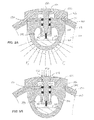
- FIG 4 is a side cross-section showing a downhole tool 100 having a sensor and stabilizer arrangement according to the present disclosure.
- the tool 100 can be used on a drilling assembly, such as discussed previously in Figure 1 .
- the tool 100 includes a downhole tubular 120, such as a drill collar or other drilling body.
- the drill collar 120 carries a sensor component, which includes a sensor housing 140 and sensor 150 for MWD/LWD applications in a borehole.
- the drill collar 120 can have an internal bore 122 for passage of drilling fluid and can have an outside surface 123 with a protective sheathing.
- the tool's sensor housing 140 disposes in a receptacle or pocket 124 formed on the outersurface 123 of the drill collar 120.
- the sensor housing 140 holds the borehole sensor 150 beyond the collar's outersurface 123 so the sensor 150 can be positioned in closer proximity to a borehole wall (not shown) for measuring parameters of interest.
- the sensor 150 can be any LWD/MWD sensor,detector, or other device used in the art, including, but not limited to, a resistivity imager, a gamma sensor, an extendable formation testing sensor, a transducer, a transceiver, a receiver, a transmitter, acoustic element, etc.
- the sensor housing 140 can be made from a suitable alloy.
- the drill collar 120 has a stabilizer 130 disposed thereon to stabilize the drill collar 120 during operation and to position the sensor 150 closer to the borehole wall.
- the stabilizer 130 can affix to the drill collar 120 using any of the common techniques known in the art.
- the stabilizer 130 can be heat shrunk onto the collar 120, and/or ends 136 of the stabilizer 130 can be affixed by welding, fasteners, or the like.
- the sensor housing 140 mounts directly to the underside or undersurface 134 of the stabilizer 130 and preferably mounts at one of the extended stabilizer blades 132.
- the sensor housing 140 is essentially supported at its circumferential distance on the drill collar 120 independent of the receptacle 124. Accordingly, the housing 140 "floats" or “suspends” in the drill collar's receptacle 124. As shown in Figure 4 , for example, the sensor housing 140 is shown disposed in, but not mounted in, the sensor receptacle 124 of the drill collar 120.
- a top surface146 of the sensor housing 140 mounts directlyto the undersurface 134 of the stabilizer 130 so that sensor openings in the housing 140 align with correspondingopenings in the stabilizer 130.
- support i.e., shims, spacers, shock absorbers, etc.
- shims spacers, shock absorbers, etc.
- the sensor housing 140 has a central passage or compartment 144 in which electronic components 154 of the sensor 150 mount.
- the electronic components 154 include a circuit board, power supply, and other elements needed for operation of the sensor 150.
- the internal components 154 canoperatively couple to one or more external sensor elements152 exposed on the surface of the stabilizer 150, but this depends on the sensor 150 used as some sensors may not require such an exposed element 152.
- the sensor element 152 is intended to interact with the borehole wall, annulus, etc. to obtain measurements of interest.
- End caps 148 affix to open ends of the housing 140 to seal the housing's compartment 144 so the electronic components 154 can be protected from pressures and drilling fluid. These end caps 148 can have passages to communicate electric wiring, hydraulics, or the like between the sensor components 154 and other parts of the tool 100, such as memory or telemetry components.
- Figure 5A is an end view of the drill collar 120, showing the arrangement of the stabilizer 130 and blades 132 about the collar's outer surface 123.
- the end-section of Figure 5B shows the sensor housing 140 disposed in the collar's receptacle 124 and abutted against the undersurface 134 of the stabilizer 130 at one of the blades 132.
- the sensor element 152 is shown exposed on the surface of the blade 132 and extending into the housing's compartment144 where the sensor element 152 operatively couples to the electronic components 154.
- FIG. 5C shows the sensor housing 140 mounted directly to (i.e., directly attached or affixed to)the collar's undersurface 134 using fasteners 160.
- the sensor component i.e., housing 140 and sensor 150
- the sensor component need not be disposed at a blade, if any, on the stabilizer 130.
- the drill collar 120 has its receptacle 124 formed in its outer surface 123 using conventional techniques.
- Various channels or passages may be defined in the collar 120 to communicate electronic wiring, hydraulics, and the like to any components to be held in the receptacle 124.
- the sensor housing 140 does not mount to the drill collar 120 so fastening holes may not be present, although various alignment holes (not shown) may be provided in the receptacle's bottom surface to receive alignment pins or the like so the housing 140 can be aligned in the receptacle 124.
- the sensor housing 140 is a pressure housing, and as shown in Figures 6B-1 and 6B-2 , the housing 140 can have an elongated, cylindrical body 142, although other shapes such as rectilinear shapes can be used.
- the body 142 defines theinternal compartment 144 for electronics and has one or moremounting surfaces or platforms 146 with fastener holes 147, alignment pin holes, and sensor holes 145 for aligning with holes in the stabilizer 130 as discussed below.
- alignment for the housing 140 is preferably accomplished using pins (not shown) between the sensorhousing 140 and the stabilizer 130.
- the stabilizer 130 is typically a cylindrical sleeve and has a number of outward extending blades 132, ribs, arms, or other features that increase the outer dimension of the stabilizer 130.
- the stabilizer 130 fits over the drill collar 120 and mounts thereon using techniques known in the art, such as heat shrinking, welding, bolting, and the like.
- the stabilizer 130 has a number of holes or openings defined in one of the blades 132 or elsewhere, including sensor openings 135 for portions of the sensor 150 to face the borehole environs.
- Other openings 137 are mounting pin holes to receive mounting bolts or fasteners (160) to hold the sensor housing 140 underneath the stabilizer 130, as discussed previously.
- the sensor housing 140 is outfitted with the components and electronics of the sensor 150, end caps 148, etc. Assemblers then set the housing 140 temporarily in the collar's receptacle 124. Assemblers then slide the stabilizer 130 shown in Figure 6C over the drill collar's outer surface 123 while the sensor housing 140 rests in the receptacle124. When properly positioned, assemblers then position fasteners 160 through openings 137 in the stabilizer 130 to affix to the fastener holes 147 on the housing's mounting surface 146. As the fasteners are tightened, the sensor housing 140 "floats" or “suspends" in the collar's receptacle 124 and mountsdirectly to the underside of the stabilizer 130. The sensor element152 can then be installed as needed into the sensor openings 135 in the stabilizer 130 to connect with the electronic components 154 installed in the housing 140 underneath.
- Figures 7A-7B show the disclosed sensor and stabilizer arrangement for different sized boreholes.
- the radius R 1 of a first borehole BH 1 ( Fig. 7A ) is smaller than the radius R 2 of a second borehole BH 2 ( Fig. 7B ).
- the same sized drill collar 120 may be used in some circumstances to drill both of these boreholes BH 1 and BH 2 becauseother components of the drilling assemblymay be changed to create the different sized boreholes BH 1 and BH 2 .
- the first stabilizer 130 1 ( Fig. 7A ) for the smaller borehole BH 1 has lower profile stabilizer blades 132 1
- the other stabilizer 130 2 ( Fig. 7B ) for the larger borehole BH 2 has higher profile stabilizer blades 132 2 .
- the sensor housing 140 mounted to the undersurface 134 of the stabilizer 130 keeps the sensor 150 at similarstandoffsS 3 and S 4 from the borehole wall.
- the similar standoffs S 3 and S 4 are preferably the same, although they may vary to some degree dependent on the sensitivity and calibration of the sensor 150. Having the similar standoffs S 3 and S 4 is possible because the sensor housing 140 "floats" or “suspends” in the collar's receptacle 124 as noted above and sits at different radii R 3 and R 4 , respectively, for the different sized boreholes BH 1 and BH 2 .
- the senor 150 is calibrated electronically with processing algorithms to operate best with a particular standoff from the borehole wall.
- the particular standoff S for the sensor 150 can be maintained despite the different sized stabilizers130 1 and 130 2 needed in some drilling applications. Accordingly, operators do not need to recalibrate the sensor 150 to operate with a different standoff and do not need to use an entirely different sensor as required in the prior art.
- the disclosed arrangement offers a modular system in which the same component, including sensor 150 and housing 140, and the same drill collar 120 can be used together and in which different sized stabilizers 130 1 and 130 2 can be interchanged on the drill collar 120 depending on the borehole size.
- Figure 8 shows a detailed end-section of the sensor housing 140 mounted on the underside 134 of the stabilizer 130.
- the sensor housing 140 is disposed in the collar's receptacle 124, and the housing's mounting surface 146 is abutted against the undersurface 134 of the stabilizer 130 at one of the blades 132.
- the sensor element 152 is installed in the sensor opening 135 of the blade 132 and extends down into the sensor opening 145 in the sensor housing 140.
- Various features, such as fasteners, threads, bushings, welds, etc. are not shown, but can be used to retain the sensor component 150 in these openings 135 and 145.
- one or more sealing members 170 can be disposed between the interface of the sensor component 150 and the housing's opening 145.
- the sensor element 152 is exposed on the surface of the blade 132 and extends into the housing's sealed compartment 144 where the element 152 operatively couples to the electronic components 154.
- fluid pressure F p from the borehole as shown in Figure 9A may enter inside the drill collar's sensor receptacle124, depending on the sealing used.
- the fluid pressure F p in the receptacle 124 acts against the surfaces of the housing 140, and the net force of this fluid pressure F p preferably forces the housing's mounting surface 146 against the undersurface 134 of the stabilizer 130.
- the force of this fluid pressure F p can help hold the sensor housing 140 in place on the stabilizer's undersurface 134.
- fluid pressure F p in the borehole annulus also acts against the surfaces of the sensor element 152outside the sealing members 170 used.
- the net force of the fluid pressure F p preferably tends to hold the sensor element 152 in the stabilizer blade 132 and housing 140.
- the interior compartment 144 of the housing 140 is preferably fluidly isolated from the borehole so the electronic components 154 can be protected.
- the sealing members 170 used in the opening 145 help isolate the components 154 from fluid and help to keep the housing's interior compartment 144 at a lower pressure (e.g., atmospheric) than the borehole annulus.
- this difference in pressure between the upper and lower ends of the sensor element 152 tends to further retain the element 152 in the openings 135 and 145 of the blade 132 and housing 140.
Landscapes
- Engineering & Computer Science (AREA)
- Life Sciences & Earth Sciences (AREA)
- Geology (AREA)
- Mining & Mineral Resources (AREA)
- Physics & Mathematics (AREA)
- Environmental & Geological Engineering (AREA)
- Fluid Mechanics (AREA)
- General Life Sciences & Earth Sciences (AREA)
- Geochemistry & Mineralogy (AREA)
- Geophysics (AREA)
- Mechanical Engineering (AREA)
- Geophysics And Detection Of Objects (AREA)
Abstract
Description
-
Figure 1 shows the general configuration of adrilling system in a Measurement-While-Drilling (MWD) orLogging-While-Drilling (LWD) environment. Adownhole tool 10 disposes in a borehole BH and is operationally connected to adrill string 12 by asuitable connector 14. At its lower end, thetool 10 has adrill bit 16. Uphole, arotary drilling rig 60 rotates thedrill string 12, thedownhole tool 10, and thedrill bit 16 to drill the borehole BH. As will be appreciated, other types of borehole conveyance can be used for thedownhole tool 10. - The
downhole tool 10 has adrill collar 20, aborehole sensor 50, and anelectronics subsection 52. Thedrill collar 20 has astabilizer sleeve 30 disposed thereon, and theborehole sensor 50is mounted at astabilizer blade 32. Depending on the desired parameters of interest, the borehole sensor50 measures data in the borehole environs, and theelectronics subsection 52 can process and store the data and can telemeter the data uphole for any of the various purposes associated with LWD/MWD. - A
surface processor 64 cooperating with the electronic subsection52 may handle the data and can perform additional mathematical operations associated with standard geological applications. Processed data can then be output to arecorder 66 for storage and optionally for output as a function of measured depth thereby forming an "image" or "log" 68 of one or more parameters of interest. All throughout operations, signals can be sent downhole to vary the direction of drilling or to vary the operation of thedownhole tool 10. - There are a few techniques for mounting asensoron a
downhole tool 10 for interaction with a borehole BH. Conventional wisdom in the art has been to either install the sensor externally on a drill collar or stabilizer or to particularly configure the sensor to install on the drill collar or stabilizer. Thus, one technique simply mounts a sensorwith a plate on a portion of a drill collar. For example,U.S. Pat. No. 7,250,768 to Ritter et al. discloses a modular cross-over sub for a bottom hole drilling assembly having a stabilizer. Separate from the stabilizer, a resistivity sensor on a plate affixes to the outside of the sub where the sensor and measuring electronics are disposed. - Alternatively, a sensorcan be directly part of a stabilizer. For example,
U.S. Pat. Pub. No. 2009/0025982 discloses instrumentation devices disposed externally on a blade of a stabilizer using rings attached to the blade with screws or other attachment means. - Finally, a particularized package for a sensor can fit in a recess of a downhole tool and can have a stabilizerfit thereover. For example,
U.S. Pat. No. 6,666,285 to Jones et al. discloses a drilling conduit having a cavity particularly sized to receive aninstrument package. A portion of the package radially protrudes a distance, and an alignment channel in a stabilizer element is dimensioned to receive the protruding portion of the instrument package. For ease of manufacturing, the alignment channel extends the entire length of the stabilizer element. - As a particular example,
Figure 2 is a side cross-section of a portion of a downhole tool10 having a sensor and stabilizer arrangement according to the prior art.Thedrill collar 20 is shown with itsinternal bore 22 for passage of drilling fluid. A sensor housing 40 fits inside a recess orpocket 24 formed on theoutside surface 23 of thedrill collar 20 and hard-mounts to thedrill collar 20 usingmounting components 42. Thesensor housing 40 has a sensor 50 (e.g., LWD downhole measurement equipment), and the hard mounting of the housing40 provides stable positioning of thesensor 50 and helps protect thesensor 50 from damage. - The sensors used for LWD/MWD applications typically measure parameters of the formation traversed by the borehole or of the borehole itself. Intypical applications, measurement accuracy is degraded by excessive and/or inconsistent standoff between the sensor and the surrounding borehole wall. To reduce standoff, the
sensor 50 may actually be positioned in the drill collar'spocket 24 at a further radial distance than the drill collar'souter surface 23. This allows thesensor 50 to position closer to the borehole wall. To help maintain the consistent standoff and to protect thesensor 50, astabilizer sleeve 30 is typically employed and is positioned directly on the drill collar'souter surface 23. When thesleeve 30 is pushed into position on the outside of thedrill collar 20, one of thestabilizer blades 32 on thestabilizer sleeve 30 fits directly over thesensor housing 40, and thestabilizer sleeve 30 can be retained using a shoulder on thedrill collar 20 and abushing 34 or other features. - Because the
housing 40 is physically mounted to thecollar 20, the distance between thesensor 50 and the borehole wall will change if the diameter of the borehole BH to be drilled is changed and if the stabilizer sleeve's diameter is also changed accordingly. This impacts the ability to make consistent measurements with thesensor 50 when used in different configurations because the changes in distance from the borehole wall will attenuate the measurements made. - For example,
Figures 3A-3B are end views diagramming the prior art sensor and stabilizer arrangement for different sized boreholes BH1 and BH2.As can be seen, the radius R1 of the first borehole BH1 is smaller than the radius R2 of the second borehole BH2. As is common, the same sizeddrill collar 20 may be used to drill both of these boreholes BH1 and BH2, while other components of the drilling system are changed to create the different sized boreholes BH1 and BH2. To account for the difference in borehole size relative to the same sizeddrill collar 20, different sizedstabilizer sleeves profile stabilizer blades 321, while the other stabilizer sleeve 302 for the larger borehole BH2 has higherprofile stabilizer blades 322. - Yet, in both circumstances, the sensor housing 40 hard-mounted to the
drill collar 20 keeps thesensor 50 at the same position on thedrill collar 20. As a result, thesensor 50 has a smaller standoff S1 relative to the wall of the smaller borehole BH1, but has a larger standoff S2 relative to the wall of the larger borehole BH2. - For measurement accuracy, the
sensor 50 is typically calibrated electronically and with processing algorithms to operate best with a particular standoff from the borehole wall. Due to thedifferentsized stabilizer sleeves Figures 3A-3B ,the standoff under which thesensor 50 measures can change. To obtain useful measurements, operators must therefore recalibrate thesensor 50 to operate with the different standoffs S1 and S2, oran entirelydifferent sensor housing 40 may need to be used so thesensor 50 will have the calibrated standoff. - As always, changes or modifications made in drilling applications can increase costs, slow down drilling operations, engender unwanted errors, and the like. For these and other reasons, the subject matter of the present disclosure is directed to overcoming, or at least reducing the effects of, one or more of the problems set forth above.
- A sensor and stabilizer arrangement for a borehole drilling tool allows a sensor to be mounted with the same standoff from a borehole wall independent of the size of stabilizer, borehole, and collar involved. The drilling tool has a drilling body, such as a drill collar, defining a receptacle exposed in itsouter surface. An electronic sensor component for anLWD/MWD-typesensor or detector disposes in the receptacle, but does not affix in the receptacle. Instead, a stabilizer fits over the drill collar and covers the receptacle and sensorcomponent, and the sensor component mounts directly to the underside of the stabilizer. For example, fasteners affix in openings on the outside surface of the stabilizer and mountthe sensorcomponent directly to the underside of the stabilizer so that the electronic component "floats" or "suspends" in the receptacle. Preferably, the sensorcomponent mounts directly to the stabilizer's underside at one of the stabilizer blades so a sensor elementexposed on the outside of the stabilizer can be positioned in proximity to the borehole wall to measure parameters of interest.
- The drill collar and sensor component can be used in different sized boreholes during drilling, and different sized stabilizer may be positioned on the drill collar to account for the different sized boreholes. Thus, the disclosed arrangement offers a modular system in which the same sensor component and drill collar can be used together and different sized stabilizers can be interchanged thereon depending on the borehole size. Because the same sized drill collar and sensor components may be used to drill larger or smaller sized boreholes, having the sensor component mounted directly underneath the stabilizer maintains the same standoff between the sensor and the borehole wall regardless of the borehole sizebeing drilled. Thus, operators can use the same sensor components for different sized boreholes and do not need to reconfigure or recalibrate the sensor to operate with a different standoff in different sized boreholes.
- The disclosed stabilizer and sensor arrangement is in contrast to the typical hard-mounting of sensor components to the drill collar in the prior art. Being coupled to the stabilizer, the sensor maintains a consistent standoff from the borehole wall, and the sensor can be calibrated to obtain the best measurements with this particular standoff. The disclosed arrangement can offer a number of benefits in the operation of a drilling tool having a sensor because the arrangement maintains a consistent distance between the borehole wall and any sensors, independent of tool body size, stabilizer size, or borehole size. As a result, there will be less measurement attenuation in comparison to the current collar mounted scheme.
- The foregoing summary is not intended to summarize each potential embodiment or every aspect of the present disclosure.
-
Fig. 1 illustrates a drilling assembly having a sensor mounted on a stabilizer of a downhole tool. -
Fig. 2 is a side cross-section of a downhole tool having a sensor and stabilizer arrangement according to the prior art. -
Figs. 3A-3B are end views showing the prior art sensor and stabilizer arrangement for different sized boreholes. -
Fig. 4 is a side cross-section showing a downhole tool having a sensor and stabilizer arrangement according to the present disclosure. -
Fig. 5A is an end view of the downhole tool ofFig. 4 . -
Figs. 5B-5C are end-sections of the downhole tool ofFig. 4 . -
Fig. 6A is a plan view of a drill collar for the disclosed sensor and stabilizer arrangement. -
Fig. 6B-1 is a plan view of a sensor housing for the disclosed sensor and stabilizer arrangement. -
Fig. 6B-2 is an end view of the sensor housing ofFig. 6B-1 . -
Fig. 6C is a plan view of a stabilizer for the disclosed sensor and stabilizer arrangement. -
Figs. 7A-7B are end views diagramming the disclosed sensor and stabilizer arrangement for different sized boreholes. -
Fig. 8 is an end-section detailingthe stabilizer, the sensor housing, and other components. -
Figs. 9A-9B are end-sections showing pressure forces acting on the sensor housing and sensor element. -
Figure 4 is a side cross-section showing adownhole tool 100 having a sensor and stabilizer arrangement according to the present disclosure. Thetool 100 can be used on a drilling assembly, such as discussed previously inFigure 1 . Thetool 100 includes adownhole tubular 120, such as a drill collar or other drilling body. Thedrill collar 120 carries a sensor component, which includes asensor housing 140 andsensor 150 for MWD/LWD applications in a borehole. As is customary, thedrill collar 120 can have aninternal bore 122 for passage of drilling fluid and can have anoutside surface 123 with a protective sheathing. - The tool's
sensor housing 140 disposes in a receptacle orpocket 124 formed on theoutersurface 123 of thedrill collar 120. Thesensor housing 140 holds theborehole sensor 150 beyond the collar'soutersurface 123 so thesensor 150 can be positioned in closer proximity to a borehole wall (not shown) for measuring parameters of interest. As will be appreciated, thesensor 150 can be any LWD/MWD sensor,detector, or other device used in the art, including, but not limited to, a resistivity imager, a gamma sensor, an extendable formation testing sensor, a transducer, a transceiver, a receiver, a transmitter, acoustic element, etc. To provide strength and to reduce electrical interference, thesensor housing 140 can be made from a suitable alloy. - The
drill collar 120 has astabilizer 130 disposed thereon to stabilize thedrill collar 120 during operation and to position thesensor 150 closer to the borehole wall.Although not shown, thestabilizer 130 can affix to thedrill collar 120 using any of the common techniques known in the art. For example, thestabilizer 130 can be heat shrunk onto thecollar 120, and/or ends 136 of thestabilizer 130 can be affixed by welding, fasteners, or the like. - Rather than hard-mounting the
sensor housing 140 to thedrill collar 120 as in the prior art, thesensor housing 140 mounts directly to the underside orundersurface 134 of thestabilizer 130 and preferably mounts at one of theextended stabilizer blades 132. By mounting directly to theundersurface 134, thesensor housing 140 is essentially supported at its circumferential distance on thedrill collar 120 independent of thereceptacle 124. Accordingly, thehousing 140 "floats" or "suspends" in the drill collar'sreceptacle 124. As shown inFigure 4 , for example, thesensor housing 140 is shown disposed in, but not mounted in, thesensor receptacle 124 of thedrill collar 120. A top surface146 of thesensor housing 140 mounts directlyto theundersurface 134 of thestabilizer 130 so that sensor openings in thehousing 140 align with correspondingopenings in thestabilizer 130. If desired, support (i.e., shims, spacers, shock absorbers, etc.) can be used in the space between thesensor housing 140 and thereceptacle 124. - The
sensor housing 140 has a central passage orcompartment 144 in whichelectronic components 154 of thesensor 150 mount. Typically, theelectronic components 154 include a circuit board, power supply, and other elements needed for operation of thesensor 150. Theinternal components 154 canoperatively couple to one or more external sensor elements152 exposed on the surface of thestabilizer 150, but this depends on thesensor 150 used as some sensors may not require such an exposedelement 152. Thesensor element 152 is intended to interact with the borehole wall, annulus, etc. to obtain measurements of interest. - End caps 148 affix to open ends of the
housing 140 to seal the housing'scompartment 144 so theelectronic components 154 can be protected from pressures and drilling fluid. These end caps 148 can have passages to communicate electric wiring, hydraulics, or the like between thesensor components 154 and other parts of thetool 100, such as memory or telemetry components. -
Figure 5A is an end view of thedrill collar 120, showing the arrangement of thestabilizer 130 andblades 132 about the collar's outer surface 123.The end-section ofFigure 5B shows thesensor housing 140 disposed in the collar'sreceptacle 124 and abutted against theundersurface 134 of thestabilizer 130 at one of theblades 132. Thesensor element 152 is shown exposed on the surface of theblade 132 and extending into the housing's compartment144 where thesensor element 152 operatively couples to theelectronic components 154. - Finally, the end-section of
Figure 5C shows thesensor housing 140 mounted directly to (i.e., directly attached or affixed to)the collar'sundersurface 134 usingfasteners 160. Although one of theblades 132 has asensor housing 140 and sensor 150as detailed herein, one or more of theother blades 132 could also have such components. Moreover, although preferred, the sensor component (i.e.,housing 140 and sensor 150) need not be disposed at a blade, if any, on thestabilizer 130. - With a general understanding of the stabilizer and sensor arrangement, assembly of the disclosed arrangement is discussed with reference to
Figures 6A through 6C . As shown in the plan view ofFigure 6A , thedrill collar 120 has itsreceptacle 124 formed in itsouter surface 123 using conventional techniques. Various channels or passages (not shown) may be defined in thecollar 120 to communicate electronic wiring, hydraulics, and the like to any components to be held in thereceptacle 124. As noted herein, thesensor housing 140 does not mount to thedrill collar 120 so fastening holes may not be present, although various alignment holes (not shown) may be provided in the receptacle's bottom surface to receive alignment pins or the like so thehousing 140 can be aligned in thereceptacle 124. - The
sensor housing 140 is a pressure housing, and as shown inFigures 6B-1 and 6B-2 , thehousing 140 can have an elongated,cylindrical body 142, although other shapes such as rectilinear shapes can be used. Thebody 142 definestheinternal compartment 144 for electronics and has one or moremounting surfaces orplatforms 146 withfastener holes 147, alignment pin holes, andsensor holes 145 for aligning with holes in thestabilizer 130 as discussed below. Although alignment can be achieved in a number of ways between the components, alignment for thehousing 140 is preferably accomplished using pins (not shown) between thesensorhousing 140 and thestabilizer 130. - As shown in
Figure 6C and elsewhere, thestabilizer 130 is typically a cylindrical sleeve and has a number of outward extendingblades 132, ribs, arms, or other features that increase the outer dimension of thestabilizer 130. Thestabilizer 130 fits over thedrill collar 120 and mounts thereon using techniques known in the art, such as heat shrinking, welding, bolting, and the like. Thestabilizer 130 has a number of holes or openings defined in one of theblades 132 or elsewhere, includingsensor openings 135 for portions of thesensor 150 to face the borehole environs.Other openings 137 are mounting pin holes to receive mounting bolts or fasteners (160) to hold thesensor housing 140 underneath thestabilizer 130, as discussed previously. - During assembly, the
sensor housing 140 is outfitted with the components and electronics of thesensor 150, end caps 148, etc. Assemblers then set thehousing 140 temporarily in the collar'sreceptacle 124. Assemblers then slide thestabilizer 130 shown inFigure 6C over the drill collar'souter surface 123 while thesensor housing 140 rests in the receptacle124. When properly positioned, assemblers then positionfasteners 160 throughopenings 137 in thestabilizer 130 to affix to the fastener holes 147 on the housing's mountingsurface 146. As the fasteners are tightened, thesensor housing 140 "floats" or "suspends" in the collar'sreceptacle 124 and mountsdirectly to the underside of thestabilizer 130. The sensor element152 can then be installed as needed into thesensor openings 135 in thestabilizer 130 to connect with theelectronic components 154 installed in thehousing 140 underneath. - The advantages of the sensor and stabilizer arrangement of the present disclosure are best illustrated with reference to
Figures 7A-7B , which show the disclosed sensor and stabilizer arrangement for different sized boreholes.As can be seen, the radius R1 of a first borehole BH1(Fig. 7A ) is smaller than the radius R2 of a second borehole BH2 (Fig. 7B ).Again, the samesized drill collar 120 may be used in some circumstances to drill both of these boreholes BH1 and BH2 becauseother components of the drilling assemblymay be changed to create the different sized boreholes BH1 and BH2. - To account for the difference in borehole size relative to the same
sized drill collar 120, different sized stabilizers1301 and 1302 are used when drilling. The first stabilizer 1301(Fig. 7A ) for the smaller borehole BH1 has lowerprofile stabilizer blades 1321, while the other stabilizer 1302(Fig. 7B ) for the larger borehole BH2 has higherprofile stabilizer blades 1322. - Yet, in both circumstances, the
sensor housing 140 mounted to theundersurface 134 of thestabilizer 130 keeps thesensor 150 at similarstandoffsS3and S4from the borehole wall. The similar standoffs S3and S4are preferably the same, although they may vary to some degree dependent on the sensitivity and calibration of thesensor 150. Having the similar standoffs S3and S4is possible because thesensor housing 140 "floats" or "suspends" in the collar'sreceptacle 124 as noted above and sits at different radii R3 and R4, respectively, for the different sized boreholes BH1 and BH2. - As noted previously, the
sensor 150 is calibrated electronically with processing algorithms to operate best with a particular standoff from the borehole wall. Using the disclosed arrangement, the particular standoff S for thesensor 150 can be maintained despite the different sized stabilizers1301 and 1302 needed in some drilling applications. Accordingly, operators do not need to recalibrate thesensor 150 to operate with a different standoff and do not need to use an entirely different sensor as required in the prior art. Thus, the disclosed arrangement offers a modular system in which the same component, includingsensor 150 andhousing 140, and thesame drill collar 120 can be used together and in which differentsized stabilizers drill collar 120 depending on the borehole size. - In addition to the above, there are other advantages of the disclosed sensor and stabilizer arrangement.
Figure 8 shows a detailed end-section of thesensor housing 140 mounted on theunderside 134 of thestabilizer 130. As noted before, thesensor housing 140 is disposed in the collar'sreceptacle 124, and the housing's mountingsurface 146 is abutted against theundersurface 134 of thestabilizer 130 at one of theblades 132. - The
sensor element 152 is installed in thesensor opening 135 of theblade 132 and extends down into thesensor opening 145 in thesensor housing 140. Various features, such as fasteners, threads, bushings, welds, etc. are not shown, but can be used to retain thesensor component 150 in theseopenings more sealing members 170 can be disposed between the interface of thesensor component 150 and the housing'sopening 145. Thus, thesensor element 152 is exposed on the surface of theblade 132 and extends into the housing's sealedcompartment 144 where theelement 152 operatively couples to theelectronic components 154. - When the
drill collar 120 is deployed downhole in a borehole, fluid pressure Fp from the borehole as shown inFigure 9A may enter inside the drill collar's sensor receptacle124, depending on the sealing used. In turn, the fluid pressure Fp in thereceptacle 124 acts against the surfaces of thehousing 140, and the net force of this fluid pressure Fppreferably forces the housing's mountingsurface 146 against theundersurface 134 of thestabilizer 130. Overall, the force of this fluid pressure Fpcan help hold thesensor housing 140 in place on the stabilizer'sundersurface 134. - As shown in
Figure 9B , fluid pressure Fp in the borehole annulus also acts against the surfaces of the sensor element 152outside the sealingmembers 170 used. The net force of the fluid pressure Fp preferably tends to hold thesensor element 152 in thestabilizer blade 132 andhousing 140. As noted previously, theinterior compartment 144 of thehousing 140 is preferably fluidly isolated from the borehole so theelectronic components 154 can be protected. The sealingmembers 170 used in theopening 145 help isolate thecomponents 154 from fluid and help to keep the housing'sinterior compartment 144 at a lower pressure (e.g., atmospheric) than the borehole annulus. Advantageously, this difference in pressure between the upper and lower ends of thesensor element 152 tends to further retain theelement 152 in theopenings blade 132 andhousing 140. - The foregoing description of preferred and other embodiments is not intended to limit or restrict the scope or applicability of the inventive concepts conceived of by the Applicants. It will be appreciated with the benefit of the present disclosure that features described above in accordance with any embodiment or aspect of the disclosed subject matter can be utilized, either alone or in combination, with any other described feature, in any other embodiment or aspect of the disclosed subject matter.
- In exchange for disclosing the inventive concepts contained herein, the Applicants desire all patent rights afforded by the appended claims. Therefore, it is intended that the appended claims include all modifications and alterations to the full extent that they come within the scope of the following claims or the equivalents thereof.
Claims (15)
- A borehole drilling tool, comprising:a drilling body having an outer surface and defining a receptacle exposed in the outer surface;at least one stabilizer having an underside, the at least one stabilizer disposed on the outer surface of the drilling body and covering the receptacle; anda sensor component for measuring in the borehole, the sensor component disposed in the receptacle and mounted directly to the underside of the at least one stabilizer.
- The tool of claim 1, wherein:the drilling body comprises a drill collar for a drillstring; orthe at least one stabilizer comprises a cylindrical sleeve fitting around the outer surface of the drilling body; orone or more fasteners dispose in openings in a topside of the at least one stabilizer and affix the sensor component to the underside of the at least one stabilizer; orthe receptacle is larger than the sensor component such that the sensor component suspends in the receptacle; orthe at least one stabilizer comprises at least one blade extending outward therefrom, the sensor component being mounted directly to the underside of the at least one stabilizer at the at least one blade.
- The tool of claim 1 or 2, where the at least one stabilizer comprises a first stabilizer, and wherein the sensor component mounted directly to the underside of the first stabilizer has a first standoff from a wall of a first sized borehole.
- The tool of claim 3, wherein the at least one stabilizer comprises a second stabilizer having a different size than the first stabilizer, the second stabilizer being interchangeably disposed on the outer surface of the drilling body instead of the first stabilizer and covering the receptacle, the sensor component mounting directly to the underside of the second stabilizer and having a second standoff from a wall of a second sized borehole, and optionally wherein the second sized borehole is larger or smaller than the first sized borehole and the second standoff is approximately equal to the first standoff.
- The tool of any one of claims 1 to 4, wherein the sensor component comprises a housing mounted directly to the underside of the at least one stabilizer and housing electronics therein; and optionally wherein the housing comprises at least one end cap disposed thereon and enclosing the electronics housed therein.
- The tool of any one of claim 1 to 5, wherein the sensor component comprises
a mounting surface disposed against the underside; and
a surrounding surface at least partially exposed in the receptacle,
wherein fluid pressure of the borehole in the receptacle acts against the surrounding surface and forces the mounting surface against the underside. - The tool of any one of claims 1 to 6,
wherein the sensor component comprises a sensor element exposed in an opening on a topside of the at least one stabilizer; and
optionally wherein the sensor element comprises one or more seals sealing the sensor element in the sensor component and isolating a first fluid pressure of the borehole from a second fluid pressure in the sensor component; and
further optionally wherein a pressure differential between the first and second fluid pressures forces the sensor element into the sensor component. - The tool of any one of claims 1 to 7, wherein the tool is a modular borehole drilling tool, and wherein the at least one stabilizer comprises:at least two stabilizers having different sizes for use in different sized boreholes, each of the at least two stabilizers interchangeably disposing on the outer surface of the drilling body and covering the receptacle,wherein the sensor component mounts directly to the underside of either of the at least two stabilizers when disposed on the drilling body, andwherein the sensor component mounted directly to either of the at least two stabilizers has a same standoff distance to walls of the different sized boreholes when disposed relative thereto.
- A borehole drilling tool assembly method, comprising:configuring a borehole sensor component for operation with a standoff from a wall of a borehole;disposing the borehole sensor component in a receptacle defined in an outside surface of a drilling body;selecting one of a plurality of stabilizers configured for a borehole size to be drilled with the drilling body, each of the stabilizers configured for a different sized borehole to be drilled with the drilling body;disposing the selected stabilizer on the drilling body over the receptacle and the borehole sensor component; andmounting the borehole sensor component directly to an underside of the selected stabilizer.
- The method of claim 9, wherein:the drilling body comprises a drill collar for a drillstring; orone or more of the stabilizers comprise a cylindrical sleeve fitting around the outer surface of the drilling body; orthe receptacle is larger than the sensor component such that the sensor component suspends in the receptacle; orone or more of the stabilizers comprise at least one blade extending outward therefrom, the sensor component being mounted directly to the underside of the stabilizer at the at least one blade.
- The method of claims 9 or 10, wherein mounting the borehole sensor component directly to the underside of the selected stabilizer comprises:disposing one or more fasteners in openings in a topside of the selected stabilizer; andaffixing the sensor component to the underside of the selected stabilizer with the one or more fasteners.
- The method of any one of claims 9 to 11, wherein disposing the borehole sensor component in the receptacle defined in the outside surface of the drilling body comprises housing electronics in the sensor component; and optionally comprises disposing at least one end cap on the sensor component to enclose the electronics housed therein.
- The method of any one of claims 9 to 12, wherein mounting the borehole sensor component directly to the underside of the selected stabilizer comprises:disposing a mounting surface of the sensor component against the underside; andexposing a surrounding surface of the sensor component at least partially in the receptacle,wherein fluid pressure of the borehole in the receptacle acts against the surrounding surface of the housing and forces the mounting surface against the underside.
- The method of any one of claims 9 to 13, wherein mounting the borehole sensor component directly to the underside of the selected stabilizer comprises:installing a sensor element into the sensor component through an opening on a topside of the selected stabilizer; andoptionally sealing the sensor element in the sensor component to isolate a first fluid pressure of the borehole from a second fluid pressure in the sensor component; andfurther optionally wherein a pressure differential between the first and second fluid pressures forces the sensor element into the sensor component
- The method of any one of claims 9 to 14, wherein the sensor component mounted directly to either of the stabilizers has a same standoff distance to walls of the different sized boreholes when disposed relative thereto.
Applications Claiming Priority (1)
| Application Number | Priority Date | Filing Date | Title |
|---|---|---|---|
| US201161551609P | 2011-10-26 | 2011-10-26 |
Publications (3)
| Publication Number | Publication Date |
|---|---|
| EP2586961A2 true EP2586961A2 (en) | 2013-05-01 |
| EP2586961A3 EP2586961A3 (en) | 2017-11-15 |
| EP2586961B1 EP2586961B1 (en) | 2019-02-27 |
Family
ID=47172353
Family Applications (1)
| Application Number | Title | Priority Date | Filing Date |
|---|---|---|---|
| EP12189400.0A Active EP2586961B1 (en) | 2011-10-26 | 2012-10-22 | Sensor mounting assembly for drill collar stabilizer |
Country Status (3)
| Country | Link |
|---|---|
| US (1) | US9243488B2 (en) |
| EP (1) | EP2586961B1 (en) |
| CA (1) | CA2792908C (en) |
Cited By (3)
| Publication number | Priority date | Publication date | Assignee | Title |
|---|---|---|---|---|
| GB2543496A (en) * | 2015-10-16 | 2017-04-26 | Reeves Wireline Tech Ltd | A borehole logging sensor and related methods |
| EP3143251A4 (en) * | 2014-05-13 | 2018-01-10 | Baker Hughes Incorporated | Multi chip module housing mounting in mwd, lwd and wireline downhole tool assemblies |
| WO2021072038A3 (en) * | 2019-10-09 | 2021-06-24 | Schlumberger Technology Corporation | Systems for securing a downhole tool to a housing |
Families Citing this family (12)
| Publication number | Priority date | Publication date | Assignee | Title |
|---|---|---|---|---|
| CA2751755C (en) * | 2009-02-12 | 2017-03-21 | Halliburton Energy Services, Inc. | A drill string tubular with a detection system mounted therein |
| CA2913703C (en) | 2013-05-31 | 2020-09-29 | Evolution Engineering Inc. | Downhole pocket electronics |
| US20200063547A1 (en) * | 2017-03-17 | 2020-02-27 | Baker Hughes, A Ge Company, Llc | Sensor configuration |
| RU175690U1 (en) * | 2017-10-18 | 2017-12-14 | Общество с ограниченной ответственностью "Научно-производственное предприятие ЭНЕРГИЯ" | A device for conducting radioactive logging while drilling a well |
| US11530579B2 (en) | 2018-01-18 | 2022-12-20 | Halliburton Energy Services, Inc. | Method and apparatus for distributed flow/seismic profiling and external support device |
| RU2698494C1 (en) * | 2019-01-17 | 2019-08-28 | Общество с ограниченной ответственностью "Научно-производственное предприятие "ЭНЕРГИЯ" | Lwd instrument stabilizer for radioactive logging |
| US11913325B2 (en) * | 2019-05-20 | 2024-02-27 | Halliburton Energy Services, Inc. | Unitized downhole tool segment |
| US11098574B2 (en) | 2019-11-25 | 2021-08-24 | Halliburton Energy Services, Inc. | Sensor with integrated window |
| US11506046B2 (en) | 2020-12-16 | 2022-11-22 | Baker Hughes Oilfield Operations Llc | Instrumented coupling electronics |
| WO2022132995A1 (en) * | 2020-12-16 | 2022-06-23 | Baker Hughes Oilfield Operations Llc | Top side coupling gauge mandrel |
| US12018538B1 (en) * | 2023-03-22 | 2024-06-25 | Halliburton Energy Services, Inc. | Compression sleeve structure for mounting magnets in downhole nuclear magnetic resonance application |
| US12416211B1 (en) * | 2024-03-14 | 2025-09-16 | Saudi Arabian Oil Company | Cuttings trap for “at bit” measurement of drilled cuttings |
Citations (3)
| Publication number | Priority date | Publication date | Assignee | Title |
|---|---|---|---|---|
| US6666285B2 (en) | 2002-02-15 | 2003-12-23 | Precision Drilling Technology Services Group Inc. | Logging-while-drilling apparatus and methods for measuring density |
| US7250768B2 (en) | 2001-04-18 | 2007-07-31 | Baker Hughes Incorporated | Apparatus and method for resistivity measurements during rotational drilling |
| US20090025982A1 (en) | 2007-07-26 | 2009-01-29 | Hall David R | Stabilizer Assembly |
Family Cites Families (29)
| Publication number | Priority date | Publication date | Assignee | Title |
|---|---|---|---|---|
| US5130950A (en) * | 1990-05-16 | 1992-07-14 | Schlumberger Technology Corporation | Ultrasonic measurement apparatus |
| DE4017761A1 (en) * | 1990-06-01 | 1991-12-05 | Eastman Christensen Co | DRILLING TOOL FOR DRILLING HOLES IN SUBSTRATE ROCK INFORMATION |
| GB2252623B (en) * | 1991-01-15 | 1994-10-19 | Teleco Oilfield Services Inc | A method for analyzing formation data from a formation evaluation measurement while drilling logging tool |
| US5250806A (en) * | 1991-03-18 | 1993-10-05 | Schlumberger Technology Corporation | Stand-off compensated formation measurements apparatus and method |
| US5235285A (en) * | 1991-10-31 | 1993-08-10 | Schlumberger Technology Corporation | Well logging apparatus having toroidal induction antenna for measuring, while drilling, resistivity of earth formations |
| US5339037A (en) * | 1992-10-09 | 1994-08-16 | Schlumberger Technology Corporation | Apparatus and method for determining the resistivity of earth formations |
| US5200705A (en) * | 1991-10-31 | 1993-04-06 | Schlumberger Technology Corporation | Dipmeter apparatus and method using transducer array having longitudinally spaced transducers |
| US5332048A (en) * | 1992-10-23 | 1994-07-26 | Halliburton Company | Method and apparatus for automatic closed loop drilling system |
| US5451779A (en) * | 1993-12-15 | 1995-09-19 | Baroid Corporation | Formation density measurement apparatus and method |
| US5631563A (en) | 1994-12-20 | 1997-05-20 | Schlumbreger Technology Corporation | Resistivity antenna shield, wear band and stabilizer assembly for measuring-while-drilling tool |
| US6581455B1 (en) * | 1995-03-31 | 2003-06-24 | Baker Hughes Incorporated | Modified formation testing apparatus with borehole grippers and method of formation testing |
| US6032748A (en) * | 1997-06-06 | 2000-03-07 | Smith International, Inc. | Non-rotatable stabilizer and torque reducer |
| US6173793B1 (en) | 1998-12-18 | 2001-01-16 | Baker Hughes Incorporated | Measurement-while-drilling devices with pad mounted sensors |
| US6622803B2 (en) | 2000-03-22 | 2003-09-23 | Rotary Drilling Technology, Llc | Stabilizer for use in a drill string |
| US6564883B2 (en) | 2000-11-30 | 2003-05-20 | Baker Hughes Incorporated | Rib-mounted logging-while-drilling (LWD) sensors |
| US6600321B2 (en) | 2001-04-18 | 2003-07-29 | Baker Hughes Incorporated | Apparatus and method for wellbore resistivity determination and imaging using capacitive coupling |
| CA2357539C (en) * | 2001-09-21 | 2006-02-14 | Fred Zillinger | Downhole gauge carrier apparatus |
| US20040237640A1 (en) * | 2003-05-29 | 2004-12-02 | Baker Hughes, Incorporated | Method and apparatus for measuring in-situ rock moduli and strength |
| US6942043B2 (en) * | 2003-06-16 | 2005-09-13 | Baker Hughes Incorporated | Modular design for LWD/MWD collars |
| US7284605B2 (en) * | 2004-09-28 | 2007-10-23 | Schlumberger Technology Corporation | Apparatus and methods for reducing stand-off effects of a downhole tool |
| US7394257B2 (en) * | 2005-03-30 | 2008-07-01 | Schlumberger Technology Corporation | Modular downhole tool system |
| US7913806B2 (en) * | 2005-05-10 | 2011-03-29 | Schlumberger Technology Corporation | Enclosures for containing transducers and electronics on a downhole tool |
| US8256565B2 (en) * | 2005-05-10 | 2012-09-04 | Schlumberger Technology Corporation | Enclosures for containing transducers and electronics on a downhole tool |
| BRPI0814280A2 (en) * | 2008-04-08 | 2015-02-03 | Halliburton Energy Serv Inc | RESISTIVITY IMAGE TRAINING TOOL, AND RESISTIVITY IMAGE TRAINING METHOD |
| EP2361394B1 (en) * | 2008-11-24 | 2022-01-12 | Halliburton Energy Services, Inc. | A high frequency dielectric measurement tool |
| US8225868B2 (en) | 2008-12-11 | 2012-07-24 | Schlumberger Technology Corporation | Apparatus and method for mounting acoustic sensors closer to a borehole wall |
| US8373412B2 (en) * | 2009-01-23 | 2013-02-12 | Baker Hughes Incorporated | NMR-LWD imaging tool |
| US9062531B2 (en) * | 2010-03-16 | 2015-06-23 | Tool Joint Products, Llc | System and method for measuring borehole conditions, in particular, verification of a final borehole diameter |
| US20120031669A1 (en) * | 2010-08-06 | 2012-02-09 | The Gearhart Companies, Inc. | Memory Logging Drill Bit With Connectable Pulser |
-
2012
- 2012-10-15 US US13/651,864 patent/US9243488B2/en active Active
- 2012-10-22 EP EP12189400.0A patent/EP2586961B1/en active Active
- 2012-10-22 CA CA2792908A patent/CA2792908C/en active Active
Patent Citations (3)
| Publication number | Priority date | Publication date | Assignee | Title |
|---|---|---|---|---|
| US7250768B2 (en) | 2001-04-18 | 2007-07-31 | Baker Hughes Incorporated | Apparatus and method for resistivity measurements during rotational drilling |
| US6666285B2 (en) | 2002-02-15 | 2003-12-23 | Precision Drilling Technology Services Group Inc. | Logging-while-drilling apparatus and methods for measuring density |
| US20090025982A1 (en) | 2007-07-26 | 2009-01-29 | Hall David R | Stabilizer Assembly |
Cited By (6)
| Publication number | Priority date | Publication date | Assignee | Title |
|---|---|---|---|---|
| EP3143251A4 (en) * | 2014-05-13 | 2018-01-10 | Baker Hughes Incorporated | Multi chip module housing mounting in mwd, lwd and wireline downhole tool assemblies |
| GB2543496A (en) * | 2015-10-16 | 2017-04-26 | Reeves Wireline Tech Ltd | A borehole logging sensor and related methods |
| GB2543496B (en) * | 2015-10-16 | 2017-11-29 | Reeves Wireline Tech Ltd | A borehole logging sensor and related methods |
| US9995845B2 (en) | 2015-10-16 | 2018-06-12 | Reeves Wireline Technologies Limited | Borehole logging sensor and related methods |
| WO2021072038A3 (en) * | 2019-10-09 | 2021-06-24 | Schlumberger Technology Corporation | Systems for securing a downhole tool to a housing |
| US11933114B2 (en) | 2019-10-09 | 2024-03-19 | Schlumberger Technology Corporation | Systems for securing a downhole tool to a housing |
Also Published As
| Publication number | Publication date |
|---|---|
| US9243488B2 (en) | 2016-01-26 |
| US20130105222A1 (en) | 2013-05-02 |
| CA2792908C (en) | 2015-04-28 |
| EP2586961A3 (en) | 2017-11-15 |
| EP2586961B1 (en) | 2019-02-27 |
| CA2792908A1 (en) | 2013-04-26 |
Similar Documents
| Publication | Publication Date | Title |
|---|---|---|
| US9243488B2 (en) | Sensor mounting assembly for drill collar stabilizer | |
| CA2761819C (en) | Downhole sensor tool for nuclear measurements | |
| CN100516929C (en) | Combined propagation and transverse resistivity downhole instrument | |
| US11692431B2 (en) | Electronic module housing for downhole use | |
| US9671211B2 (en) | Method and apparatus for measuring linear displacement | |
| US20170241255A1 (en) | Back up directional and inclination sensors and method of operating same | |
| US20040251048A1 (en) | Modular design for LWD/MWD collars | |
| CA2761814C (en) | Downhole sensor tool with a sealed sensor outsert | |
| EP3464818B1 (en) | Formation tester tool | |
| NO347424B1 (en) | An apparatus for retaining electronic components in a downhole component coupling mechanism, and a method of coupling downhole components | |
| US20060266518A1 (en) | Self contained temperature sensor for borehole systems | |
| US9605527B2 (en) | Reducing rotational vibration in rotational measurements | |
| NO348418B1 (en) | Electrical isolation to reduce magnetometer interference | |
| US20210404319A1 (en) | Integrated collar sensor for measuring mechanical impedance of the downhole tool | |
| US20210404317A1 (en) | Integrated collar sensor for measuring performance characteristics of a drill motor | |
| US11414981B2 (en) | Integrated gamma sensor container | |
| US20220049597A1 (en) | Integrated collar sensor for measuring health of a downhole tool | |
| BR112020017873B1 (en) | DEVICE FOR MEASURING A PARAMETER OF INTEREST AT THE BOTTOM OF THE WELL |
Legal Events
| Date | Code | Title | Description |
|---|---|---|---|
| PUAI | Public reference made under article 153(3) epc to a published international application that has entered the european phase |
Free format text: ORIGINAL CODE: 0009012 |
|
| AK | Designated contracting states |
Kind code of ref document: A2 Designated state(s): AL AT BE BG CH CY CZ DE DK EE ES FI FR GB GR HR HU IE IS IT LI LT LU LV MC MK MT NL NO PL PT RO RS SE SI SK SM TR |
|
| AX | Request for extension of the european patent |
Extension state: BA ME |
|
| PUAL | Search report despatched |
Free format text: ORIGINAL CODE: 0009013 |
|
| AK | Designated contracting states |
Kind code of ref document: A3 Designated state(s): AL AT BE BG CH CY CZ DE DK EE ES FI FR GB GR HR HU IE IS IT LI LT LU LV MC MK MT NL NO PL PT RO RS SE SI SK SM TR |
|
| AX | Request for extension of the european patent |
Extension state: BA ME |
|
| RIC1 | Information provided on ipc code assigned before grant |
Ipc: E21B 47/01 20120101ALI20171009BHEP Ipc: E21B 17/10 20060101AFI20171009BHEP |
|
| STAA | Information on the status of an ep patent application or granted ep patent |
Free format text: STATUS: REQUEST FOR EXAMINATION WAS MADE |
|
| STAA | Information on the status of an ep patent application or granted ep patent |
Free format text: STATUS: EXAMINATION IS IN PROGRESS |
|
| 17P | Request for examination filed |
Effective date: 20180509 |
|
| RBV | Designated contracting states (corrected) |
Designated state(s): AL AT BE BG CH CY CZ DE DK EE ES FI FR GB GR HR HU IE IS IT LI LT LU LV MC MK MT NL NO PL PT RO RS SE SI SK SM TR |
|
| 17Q | First examination report despatched |
Effective date: 20180604 |
|
| GRAP | Despatch of communication of intention to grant a patent |
Free format text: ORIGINAL CODE: EPIDOSNIGR1 |
|
| STAA | Information on the status of an ep patent application or granted ep patent |
Free format text: STATUS: GRANT OF PATENT IS INTENDED |
|
| INTG | Intention to grant announced |
Effective date: 20180913 |
|
| GRAS | Grant fee paid |
Free format text: ORIGINAL CODE: EPIDOSNIGR3 |
|
| GRAA | (expected) grant |
Free format text: ORIGINAL CODE: 0009210 |
|
| STAA | Information on the status of an ep patent application or granted ep patent |
Free format text: STATUS: THE PATENT HAS BEEN GRANTED |
|
| AK | Designated contracting states |
Kind code of ref document: B1 Designated state(s): AL AT BE BG CH CY CZ DE DK EE ES FI FR GB GR HR HU IE IS IT LI LT LU LV MC MK MT NL NO PL PT RO RS SE SI SK SM TR |
|
| REG | Reference to a national code |
Ref country code: GB Ref legal event code: FG4D |
|
| REG | Reference to a national code |
Ref country code: CH Ref legal event code: EP |
|
| REG | Reference to a national code |
Ref country code: DE Ref legal event code: R096 Ref document number: 602012057070 Country of ref document: DE |
|
| REG | Reference to a national code |
Ref country code: AT Ref legal event code: REF Ref document number: 1101603 Country of ref document: AT Kind code of ref document: T Effective date: 20190315 |
|
| REG | Reference to a national code |
Ref country code: IE Ref legal event code: FG4D |
|
| REG | Reference to a national code |
Ref country code: NL Ref legal event code: MP Effective date: 20190227 |
|
| REG | Reference to a national code |
Ref country code: LT Ref legal event code: MG4D |
|
| REG | Reference to a national code |
Ref country code: NO Ref legal event code: T2 Effective date: 20190227 |
|
| PG25 | Lapsed in a contracting state [announced via postgrant information from national office to epo] |
Ref country code: PT Free format text: LAPSE BECAUSE OF FAILURE TO SUBMIT A TRANSLATION OF THE DESCRIPTION OR TO PAY THE FEE WITHIN THE PRESCRIBED TIME-LIMIT Effective date: 20190627 Ref country code: NL Free format text: LAPSE BECAUSE OF FAILURE TO SUBMIT A TRANSLATION OF THE DESCRIPTION OR TO PAY THE FEE WITHIN THE PRESCRIBED TIME-LIMIT Effective date: 20190227 Ref country code: FI Free format text: LAPSE BECAUSE OF FAILURE TO SUBMIT A TRANSLATION OF THE DESCRIPTION OR TO PAY THE FEE WITHIN THE PRESCRIBED TIME-LIMIT Effective date: 20190227 Ref country code: LT Free format text: LAPSE BECAUSE OF FAILURE TO SUBMIT A TRANSLATION OF THE DESCRIPTION OR TO PAY THE FEE WITHIN THE PRESCRIBED TIME-LIMIT Effective date: 20190227 Ref country code: SE Free format text: LAPSE BECAUSE OF FAILURE TO SUBMIT A TRANSLATION OF THE DESCRIPTION OR TO PAY THE FEE WITHIN THE PRESCRIBED TIME-LIMIT Effective date: 20190227 |
|
| PG25 | Lapsed in a contracting state [announced via postgrant information from national office to epo] |
Ref country code: BG Free format text: LAPSE BECAUSE OF FAILURE TO SUBMIT A TRANSLATION OF THE DESCRIPTION OR TO PAY THE FEE WITHIN THE PRESCRIBED TIME-LIMIT Effective date: 20190527 Ref country code: HR Free format text: LAPSE BECAUSE OF FAILURE TO SUBMIT A TRANSLATION OF THE DESCRIPTION OR TO PAY THE FEE WITHIN THE PRESCRIBED TIME-LIMIT Effective date: 20190227 Ref country code: GR Free format text: LAPSE BECAUSE OF FAILURE TO SUBMIT A TRANSLATION OF THE DESCRIPTION OR TO PAY THE FEE WITHIN THE PRESCRIBED TIME-LIMIT Effective date: 20190528 Ref country code: IS Free format text: LAPSE BECAUSE OF FAILURE TO SUBMIT A TRANSLATION OF THE DESCRIPTION OR TO PAY THE FEE WITHIN THE PRESCRIBED TIME-LIMIT Effective date: 20190627 Ref country code: LV Free format text: LAPSE BECAUSE OF FAILURE TO SUBMIT A TRANSLATION OF THE DESCRIPTION OR TO PAY THE FEE WITHIN THE PRESCRIBED TIME-LIMIT Effective date: 20190227 Ref country code: RS Free format text: LAPSE BECAUSE OF FAILURE TO SUBMIT A TRANSLATION OF THE DESCRIPTION OR TO PAY THE FEE WITHIN THE PRESCRIBED TIME-LIMIT Effective date: 20190227 |
|
| REG | Reference to a national code |
Ref country code: AT Ref legal event code: MK05 Ref document number: 1101603 Country of ref document: AT Kind code of ref document: T Effective date: 20190227 |
|
| PG25 | Lapsed in a contracting state [announced via postgrant information from national office to epo] |
Ref country code: CZ Free format text: LAPSE BECAUSE OF FAILURE TO SUBMIT A TRANSLATION OF THE DESCRIPTION OR TO PAY THE FEE WITHIN THE PRESCRIBED TIME-LIMIT Effective date: 20190227 Ref country code: RO Free format text: LAPSE BECAUSE OF FAILURE TO SUBMIT A TRANSLATION OF THE DESCRIPTION OR TO PAY THE FEE WITHIN THE PRESCRIBED TIME-LIMIT Effective date: 20190227 Ref country code: IT Free format text: LAPSE BECAUSE OF FAILURE TO SUBMIT A TRANSLATION OF THE DESCRIPTION OR TO PAY THE FEE WITHIN THE PRESCRIBED TIME-LIMIT Effective date: 20190227 Ref country code: SK Free format text: LAPSE BECAUSE OF FAILURE TO SUBMIT A TRANSLATION OF THE DESCRIPTION OR TO PAY THE FEE WITHIN THE PRESCRIBED TIME-LIMIT Effective date: 20190227 Ref country code: ES Free format text: LAPSE BECAUSE OF FAILURE TO SUBMIT A TRANSLATION OF THE DESCRIPTION OR TO PAY THE FEE WITHIN THE PRESCRIBED TIME-LIMIT Effective date: 20190227 Ref country code: DK Free format text: LAPSE BECAUSE OF FAILURE TO SUBMIT A TRANSLATION OF THE DESCRIPTION OR TO PAY THE FEE WITHIN THE PRESCRIBED TIME-LIMIT Effective date: 20190227 Ref country code: EE Free format text: LAPSE BECAUSE OF FAILURE TO SUBMIT A TRANSLATION OF THE DESCRIPTION OR TO PAY THE FEE WITHIN THE PRESCRIBED TIME-LIMIT Effective date: 20190227 Ref country code: AL Free format text: LAPSE BECAUSE OF FAILURE TO SUBMIT A TRANSLATION OF THE DESCRIPTION OR TO PAY THE FEE WITHIN THE PRESCRIBED TIME-LIMIT Effective date: 20190227 |
|
| REG | Reference to a national code |
Ref country code: DE Ref legal event code: R097 Ref document number: 602012057070 Country of ref document: DE |
|
| PG25 | Lapsed in a contracting state [announced via postgrant information from national office to epo] |
Ref country code: PL Free format text: LAPSE BECAUSE OF FAILURE TO SUBMIT A TRANSLATION OF THE DESCRIPTION OR TO PAY THE FEE WITHIN THE PRESCRIBED TIME-LIMIT Effective date: 20190227 Ref country code: SM Free format text: LAPSE BECAUSE OF FAILURE TO SUBMIT A TRANSLATION OF THE DESCRIPTION OR TO PAY THE FEE WITHIN THE PRESCRIBED TIME-LIMIT Effective date: 20190227 |
|
| PG25 | Lapsed in a contracting state [announced via postgrant information from national office to epo] |
Ref country code: AT Free format text: LAPSE BECAUSE OF FAILURE TO SUBMIT A TRANSLATION OF THE DESCRIPTION OR TO PAY THE FEE WITHIN THE PRESCRIBED TIME-LIMIT Effective date: 20190227 |
|
| PLBE | No opposition filed within time limit |
Free format text: ORIGINAL CODE: 0009261 |
|
| STAA | Information on the status of an ep patent application or granted ep patent |
Free format text: STATUS: NO OPPOSITION FILED WITHIN TIME LIMIT |
|
| 26N | No opposition filed |
Effective date: 20191128 |
|
| PG25 | Lapsed in a contracting state [announced via postgrant information from national office to epo] |
Ref country code: SI Free format text: LAPSE BECAUSE OF FAILURE TO SUBMIT A TRANSLATION OF THE DESCRIPTION OR TO PAY THE FEE WITHIN THE PRESCRIBED TIME-LIMIT Effective date: 20190227 |
|
| PG25 | Lapsed in a contracting state [announced via postgrant information from national office to epo] |
Ref country code: TR Free format text: LAPSE BECAUSE OF FAILURE TO SUBMIT A TRANSLATION OF THE DESCRIPTION OR TO PAY THE FEE WITHIN THE PRESCRIBED TIME-LIMIT Effective date: 20190227 |
|
| REG | Reference to a national code |
Ref country code: DE Ref legal event code: R119 Ref document number: 602012057070 Country of ref document: DE |
|
| PG25 | Lapsed in a contracting state [announced via postgrant information from national office to epo] |
Ref country code: MC Free format text: LAPSE BECAUSE OF FAILURE TO SUBMIT A TRANSLATION OF THE DESCRIPTION OR TO PAY THE FEE WITHIN THE PRESCRIBED TIME-LIMIT Effective date: 20190227 |
|
| REG | Reference to a national code |
Ref country code: CH Ref legal event code: PL |
|
| REG | Reference to a national code |
Ref country code: NO Ref legal event code: PLED Effective date: 20200525 |
|
| PG25 | Lapsed in a contracting state [announced via postgrant information from national office to epo] |
Ref country code: LI Free format text: LAPSE BECAUSE OF NON-PAYMENT OF DUE FEES Effective date: 20191031 Ref country code: DE Free format text: LAPSE BECAUSE OF NON-PAYMENT OF DUE FEES Effective date: 20200501 Ref country code: LU Free format text: LAPSE BECAUSE OF NON-PAYMENT OF DUE FEES Effective date: 20191022 Ref country code: CH Free format text: LAPSE BECAUSE OF NON-PAYMENT OF DUE FEES Effective date: 20191031 |
|
| REG | Reference to a national code |
Ref country code: BE Ref legal event code: MM Effective date: 20191031 |
|
| PG25 | Lapsed in a contracting state [announced via postgrant information from national office to epo] |
Ref country code: BE Free format text: LAPSE BECAUSE OF NON-PAYMENT OF DUE FEES Effective date: 20191031 |
|
| REG | Reference to a national code |
Ref country code: GB Ref legal event code: 732E Free format text: REGISTERED BETWEEN 20200813 AND 20200819 |
|
| PG25 | Lapsed in a contracting state [announced via postgrant information from national office to epo] |
Ref country code: IE Free format text: LAPSE BECAUSE OF NON-PAYMENT OF DUE FEES Effective date: 20191022 Ref country code: FR Free format text: LAPSE BECAUSE OF NON-PAYMENT OF DUE FEES Effective date: 20191031 |
|
| REG | Reference to a national code |
Ref country code: GB Ref legal event code: 732E Free format text: REGISTERED BETWEEN 20201119 AND 20201125 |
|
| PG25 | Lapsed in a contracting state [announced via postgrant information from national office to epo] |
Ref country code: CY Free format text: LAPSE BECAUSE OF FAILURE TO SUBMIT A TRANSLATION OF THE DESCRIPTION OR TO PAY THE FEE WITHIN THE PRESCRIBED TIME-LIMIT Effective date: 20190227 |
|
| PG25 | Lapsed in a contracting state [announced via postgrant information from national office to epo] |
Ref country code: MT Free format text: LAPSE BECAUSE OF FAILURE TO SUBMIT A TRANSLATION OF THE DESCRIPTION OR TO PAY THE FEE WITHIN THE PRESCRIBED TIME-LIMIT Effective date: 20190227 Ref country code: HU Free format text: LAPSE BECAUSE OF FAILURE TO SUBMIT A TRANSLATION OF THE DESCRIPTION OR TO PAY THE FEE WITHIN THE PRESCRIBED TIME-LIMIT; INVALID AB INITIO Effective date: 20121022 |
|
| REG | Reference to a national code |
Ref country code: GB Ref legal event code: 732E Free format text: REGISTERED BETWEEN 20210729 AND 20210804 |
|
| PG25 | Lapsed in a contracting state [announced via postgrant information from national office to epo] |
Ref country code: MK Free format text: LAPSE BECAUSE OF FAILURE TO SUBMIT A TRANSLATION OF THE DESCRIPTION OR TO PAY THE FEE WITHIN THE PRESCRIBED TIME-LIMIT Effective date: 20190227 |
|
| PGFP | Annual fee paid to national office [announced via postgrant information from national office to epo] |
Ref country code: GB Payment date: 20250904 Year of fee payment: 14 |
|
| PGFP | Annual fee paid to national office [announced via postgrant information from national office to epo] |
Ref country code: NO Payment date: 20251009 Year of fee payment: 14 |