EP2586600B1 - Method and apparatus for producing composite fillers - Google Patents
Method and apparatus for producing composite fillers Download PDFInfo
- Publication number
- EP2586600B1 EP2586600B1 EP12182861.0A EP12182861A EP2586600B1 EP 2586600 B1 EP2586600 B1 EP 2586600B1 EP 12182861 A EP12182861 A EP 12182861A EP 2586600 B1 EP2586600 B1 EP 2586600B1
- Authority
- EP
- European Patent Office
- Prior art keywords
- strips
- stack
- die
- filler
- ply
- Prior art date
- Legal status (The legal status is an assumption and is not a legal conclusion. Google has not performed a legal analysis and makes no representation as to the accuracy of the status listed.)
- Active
Links
- 239000000945 filler Substances 0.000 title claims description 103
- 239000002131 composite material Substances 0.000 title claims description 62
- 238000000034 method Methods 0.000 title claims description 56
- 239000000853 adhesive Substances 0.000 claims description 21
- 230000001070 adhesive effect Effects 0.000 claims description 21
- 238000004519 manufacturing process Methods 0.000 claims description 19
- 238000005096 rolling process Methods 0.000 claims description 2
- 239000000835 fiber Substances 0.000 description 30
- 238000010586 diagram Methods 0.000 description 8
- 230000002093 peripheral effect Effects 0.000 description 5
- 239000000463 material Substances 0.000 description 4
- 238000005056 compaction Methods 0.000 description 3
- 238000005520 cutting process Methods 0.000 description 3
- 230000007423 decrease Effects 0.000 description 3
- 238000009787 hand lay-up Methods 0.000 description 3
- 238000003825 pressing Methods 0.000 description 3
- 230000008569 process Effects 0.000 description 3
- 239000002313 adhesive film Substances 0.000 description 2
- 238000005336 cracking Methods 0.000 description 2
- 238000010438 heat treatment Methods 0.000 description 2
- 238000010030 laminating Methods 0.000 description 2
- 238000012423 maintenance Methods 0.000 description 2
- 238000012545 processing Methods 0.000 description 2
- 239000002990 reinforced plastic Substances 0.000 description 2
- 230000002787 reinforcement Effects 0.000 description 2
- 239000011347 resin Substances 0.000 description 2
- 229920005989 resin Polymers 0.000 description 2
- 239000007787 solid Substances 0.000 description 2
- 239000003351 stiffener Substances 0.000 description 2
- 229920000049 Carbon (fiber) Polymers 0.000 description 1
- 101000793686 Homo sapiens Azurocidin Proteins 0.000 description 1
- 239000004917 carbon fiber Substances 0.000 description 1
- 230000008859 change Effects 0.000 description 1
- 238000013461 design Methods 0.000 description 1
- 230000007613 environmental effect Effects 0.000 description 1
- 238000001125 extrusion Methods 0.000 description 1
- 239000004744 fabric Substances 0.000 description 1
- 239000003365 glass fiber Substances 0.000 description 1
- 230000010354 integration Effects 0.000 description 1
- 238000005304 joining Methods 0.000 description 1
- 230000004048 modification Effects 0.000 description 1
- 238000012986 modification Methods 0.000 description 1
- 235000012149 noodles Nutrition 0.000 description 1
- 230000008520 organization Effects 0.000 description 1
- 238000009419 refurbishment Methods 0.000 description 1
- 239000012783 reinforcing fiber Substances 0.000 description 1
- 230000007704 transition Effects 0.000 description 1
Images


Classifications
-
- B—PERFORMING OPERATIONS; TRANSPORTING
- B29—WORKING OF PLASTICS; WORKING OF SUBSTANCES IN A PLASTIC STATE IN GENERAL
- B29C—SHAPING OR JOINING OF PLASTICS; SHAPING OF MATERIAL IN A PLASTIC STATE, NOT OTHERWISE PROVIDED FOR; AFTER-TREATMENT OF THE SHAPED PRODUCTS, e.g. REPAIRING
- B29C70/00—Shaping composites, i.e. plastics material comprising reinforcements, fillers or preformed parts, e.g. inserts
- B29C70/04—Shaping composites, i.e. plastics material comprising reinforcements, fillers or preformed parts, e.g. inserts comprising reinforcements only, e.g. self-reinforcing plastics
- B29C70/28—Shaping operations therefor
- B29C70/40—Shaping or impregnating by compression not applied
- B29C70/50—Shaping or impregnating by compression not applied for producing articles of indefinite length, e.g. prepregs, sheet moulding compounds [SMC] or cross moulding compounds [XMC]
- B29C70/52—Pultrusion, i.e. forming and compressing by continuously pulling through a die
- B29C70/525—Component parts, details or accessories; Auxiliary operations
- B29C70/526—Pultrusion dies, e.g. dies with moving or rotating parts
-
- B—PERFORMING OPERATIONS; TRANSPORTING
- B29—WORKING OF PLASTICS; WORKING OF SUBSTANCES IN A PLASTIC STATE IN GENERAL
- B29C—SHAPING OR JOINING OF PLASTICS; SHAPING OF MATERIAL IN A PLASTIC STATE, NOT OTHERWISE PROVIDED FOR; AFTER-TREATMENT OF THE SHAPED PRODUCTS, e.g. REPAIRING
- B29C70/00—Shaping composites, i.e. plastics material comprising reinforcements, fillers or preformed parts, e.g. inserts
- B29C70/04—Shaping composites, i.e. plastics material comprising reinforcements, fillers or preformed parts, e.g. inserts comprising reinforcements only, e.g. self-reinforcing plastics
- B29C70/28—Shaping operations therefor
- B29C70/40—Shaping or impregnating by compression not applied
- B29C70/50—Shaping or impregnating by compression not applied for producing articles of indefinite length, e.g. prepregs, sheet moulding compounds [SMC] or cross moulding compounds [XMC]
- B29C70/52—Pultrusion, i.e. forming and compressing by continuously pulling through a die
-
- B—PERFORMING OPERATIONS; TRANSPORTING
- B29—WORKING OF PLASTICS; WORKING OF SUBSTANCES IN A PLASTIC STATE IN GENERAL
- B29D—PRODUCING PARTICULAR ARTICLES FROM PLASTICS OR FROM SUBSTANCES IN A PLASTIC STATE
- B29D99/00—Subject matter not provided for in other groups of this subclass
- B29D99/0003—Producing profiled members, e.g. beams
- B29D99/0005—Producing noodles, i.e. composite gap fillers, characterised by their construction
-
- B—PERFORMING OPERATIONS; TRANSPORTING
- B29—WORKING OF PLASTICS; WORKING OF SUBSTANCES IN A PLASTIC STATE IN GENERAL
- B29D—PRODUCING PARTICULAR ARTICLES FROM PLASTICS OR FROM SUBSTANCES IN A PLASTIC STATE
- B29D99/00—Subject matter not provided for in other groups of this subclass
- B29D99/0003—Producing profiled members, e.g. beams
- B29D99/0007—Producing profiled members, e.g. beams having a variable cross-section
-
- B—PERFORMING OPERATIONS; TRANSPORTING
- B32—LAYERED PRODUCTS
- B32B—LAYERED PRODUCTS, i.e. PRODUCTS BUILT-UP OF STRATA OF FLAT OR NON-FLAT, e.g. CELLULAR OR HONEYCOMB, FORM
- B32B37/00—Methods or apparatus for laminating, e.g. by curing or by ultrasonic bonding
- B32B37/0046—Methods or apparatus for laminating, e.g. by curing or by ultrasonic bonding characterised by constructional aspects of the apparatus
-
- B—PERFORMING OPERATIONS; TRANSPORTING
- B32—LAYERED PRODUCTS
- B32B—LAYERED PRODUCTS, i.e. PRODUCTS BUILT-UP OF STRATA OF FLAT OR NON-FLAT, e.g. CELLULAR OR HONEYCOMB, FORM
- B32B38/00—Ancillary operations in connection with laminating processes
- B32B38/0004—Cutting, tearing or severing, e.g. bursting; Cutter details
-
- B—PERFORMING OPERATIONS; TRANSPORTING
- B29—WORKING OF PLASTICS; WORKING OF SUBSTANCES IN A PLASTIC STATE IN GENERAL
- B29L—INDEXING SCHEME ASSOCIATED WITH SUBCLASS B29C, RELATING TO PARTICULAR ARTICLES
- B29L2031/00—Other particular articles
- B29L2031/001—Profiled members, e.g. beams, sections
- B29L2031/003—Profiled members, e.g. beams, sections having a profiled transverse cross-section
-
- B—PERFORMING OPERATIONS; TRANSPORTING
- B29—WORKING OF PLASTICS; WORKING OF SUBSTANCES IN A PLASTIC STATE IN GENERAL
- B29L—INDEXING SCHEME ASSOCIATED WITH SUBCLASS B29C, RELATING TO PARTICULAR ARTICLES
- B29L2031/00—Other particular articles
- B29L2031/001—Profiled members, e.g. beams, sections
- B29L2031/008—Profiled members, e.g. beams, sections having a longitudinal cross-section
-
- Y—GENERAL TAGGING OF NEW TECHNOLOGICAL DEVELOPMENTS; GENERAL TAGGING OF CROSS-SECTIONAL TECHNOLOGIES SPANNING OVER SEVERAL SECTIONS OF THE IPC; TECHNICAL SUBJECTS COVERED BY FORMER USPC CROSS-REFERENCE ART COLLECTIONS [XRACs] AND DIGESTS
- Y10—TECHNICAL SUBJECTS COVERED BY FORMER USPC
- Y10T—TECHNICAL SUBJECTS COVERED BY FORMER US CLASSIFICATION
- Y10T156/00—Adhesive bonding and miscellaneous chemical manufacture
- Y10T156/10—Methods of surface bonding and/or assembly therefor
- Y10T156/1002—Methods of surface bonding and/or assembly therefor with permanent bending or reshaping or surface deformation of self sustaining lamina
- Y10T156/1007—Running or continuous length work
- Y10T156/1023—Surface deformation only [e.g., embossing]
-
- Y—GENERAL TAGGING OF NEW TECHNOLOGICAL DEVELOPMENTS; GENERAL TAGGING OF CROSS-SECTIONAL TECHNOLOGIES SPANNING OVER SEVERAL SECTIONS OF THE IPC; TECHNICAL SUBJECTS COVERED BY FORMER USPC CROSS-REFERENCE ART COLLECTIONS [XRACs] AND DIGESTS
- Y10—TECHNICAL SUBJECTS COVERED BY FORMER USPC
- Y10T—TECHNICAL SUBJECTS COVERED BY FORMER US CLASSIFICATION
- Y10T156/00—Adhesive bonding and miscellaneous chemical manufacture
- Y10T156/10—Methods of surface bonding and/or assembly therefor
- Y10T156/1002—Methods of surface bonding and/or assembly therefor with permanent bending or reshaping or surface deformation of self sustaining lamina
- Y10T156/1028—Methods of surface bonding and/or assembly therefor with permanent bending or reshaping or surface deformation of self sustaining lamina by bending, drawing or stretch forming sheet to assume shape of configured lamina while in contact therewith
- Y10T156/1031—Methods of surface bonding and/or assembly therefor with permanent bending or reshaping or surface deformation of self sustaining lamina by bending, drawing or stretch forming sheet to assume shape of configured lamina while in contact therewith with preshaping of lamina
-
- Y—GENERAL TAGGING OF NEW TECHNOLOGICAL DEVELOPMENTS; GENERAL TAGGING OF CROSS-SECTIONAL TECHNOLOGIES SPANNING OVER SEVERAL SECTIONS OF THE IPC; TECHNICAL SUBJECTS COVERED BY FORMER USPC CROSS-REFERENCE ART COLLECTIONS [XRACs] AND DIGESTS
- Y10—TECHNICAL SUBJECTS COVERED BY FORMER USPC
- Y10T—TECHNICAL SUBJECTS COVERED BY FORMER US CLASSIFICATION
- Y10T156/00—Adhesive bonding and miscellaneous chemical manufacture
- Y10T156/10—Methods of surface bonding and/or assembly therefor
- Y10T156/1002—Methods of surface bonding and/or assembly therefor with permanent bending or reshaping or surface deformation of self sustaining lamina
- Y10T156/1043—Subsequent to assembly
- Y10T156/1044—Subsequent to assembly of parallel stacked sheets only
-
- Y—GENERAL TAGGING OF NEW TECHNOLOGICAL DEVELOPMENTS; GENERAL TAGGING OF CROSS-SECTIONAL TECHNOLOGIES SPANNING OVER SEVERAL SECTIONS OF THE IPC; TECHNICAL SUBJECTS COVERED BY FORMER USPC CROSS-REFERENCE ART COLLECTIONS [XRACs] AND DIGESTS
- Y10—TECHNICAL SUBJECTS COVERED BY FORMER USPC
- Y10T—TECHNICAL SUBJECTS COVERED BY FORMER US CLASSIFICATION
- Y10T156/00—Adhesive bonding and miscellaneous chemical manufacture
- Y10T156/10—Methods of surface bonding and/or assembly therefor
- Y10T156/1052—Methods of surface bonding and/or assembly therefor with cutting, punching, tearing or severing
- Y10T156/1062—Prior to assembly
- Y10T156/1075—Prior to assembly of plural laminae from single stock and assembling to each other or to additional lamina
-
- Y—GENERAL TAGGING OF NEW TECHNOLOGICAL DEVELOPMENTS; GENERAL TAGGING OF CROSS-SECTIONAL TECHNOLOGIES SPANNING OVER SEVERAL SECTIONS OF THE IPC; TECHNICAL SUBJECTS COVERED BY FORMER USPC CROSS-REFERENCE ART COLLECTIONS [XRACs] AND DIGESTS
- Y10—TECHNICAL SUBJECTS COVERED BY FORMER USPC
- Y10T—TECHNICAL SUBJECTS COVERED BY FORMER US CLASSIFICATION
- Y10T156/00—Adhesive bonding and miscellaneous chemical manufacture
- Y10T156/12—Surface bonding means and/or assembly means with cutting, punching, piercing, severing or tearing
- Y10T156/125—Plural severing means each acting on a different work piece
-
- Y—GENERAL TAGGING OF NEW TECHNOLOGICAL DEVELOPMENTS; GENERAL TAGGING OF CROSS-SECTIONAL TECHNOLOGIES SPANNING OVER SEVERAL SECTIONS OF THE IPC; TECHNICAL SUBJECTS COVERED BY FORMER USPC CROSS-REFERENCE ART COLLECTIONS [XRACs] AND DIGESTS
- Y10—TECHNICAL SUBJECTS COVERED BY FORMER USPC
- Y10T—TECHNICAL SUBJECTS COVERED BY FORMER US CLASSIFICATION
- Y10T156/00—Adhesive bonding and miscellaneous chemical manufacture
- Y10T156/12—Surface bonding means and/or assembly means with cutting, punching, piercing, severing or tearing
- Y10T156/1317—Means feeding plural workpieces to be joined
- Y10T156/1322—Severing before bonding or assembling of parts
- Y10T156/133—Delivering cut part to indefinite or running length web
-
- Y—GENERAL TAGGING OF NEW TECHNOLOGICAL DEVELOPMENTS; GENERAL TAGGING OF CROSS-SECTIONAL TECHNOLOGIES SPANNING OVER SEVERAL SECTIONS OF THE IPC; TECHNICAL SUBJECTS COVERED BY FORMER USPC CROSS-REFERENCE ART COLLECTIONS [XRACs] AND DIGESTS
- Y10—TECHNICAL SUBJECTS COVERED BY FORMER USPC
- Y10T—TECHNICAL SUBJECTS COVERED BY FORMER US CLASSIFICATION
- Y10T156/00—Adhesive bonding and miscellaneous chemical manufacture
- Y10T156/14—Surface bonding means and/or assembly means with shaping, scarifying, or cleaning joining surface only
Definitions
- the present disclosure generally relates to the fabrication composite structures, and deals more particularly with a method for producing fillers used to fill gaps in such structures.
- Composite structures may be fabricated by joining two or more members together. In some cases, there may be one or more gaps in areas of joints between the members that may reduce the strength of the joints. In order to strengthen the joints, the gaps are filled with fillers, sometimes also referred to as radius fillers, fillets or noodles.
- the filler may be formed from composite materials such as adhesive, prepreg tape or fabric.
- the cross section of the gap may vary in size and/or shape along its length as a result of the adjoining composite members converging or diverging from each other. For example, ply pad-ups, ply drop-offs and/or joggles on a composite skin may result in a variable gap between the skin and an overlying stiffener, such as a stringer, that is attached to the skin.
- fillers having variable cross sectional shapes were fabricated using hand layup techniques that involved laminating unidirectional fiber prepreg tape, in which the fiber orientation was parallel to the length of the gap. This hand layup technique required multiple processing steps, was labor intensive and time consuming. Additionally, fillers employing unidirectional fiber reinforcement may be subject to movement and may not exhibit the desired degree of resistance to cracking.
- US 4,440,593 describes an apparatus for producing arcuately shaped filament containing reinforced plastic composite articles which have a non-constant cross-sectional shape over their length.
- the apparatus comprises a die having a die channel of non-constant cross-sectional shape.
- the die channel is formed by a pair of first and second die-forming members.
- One of the die-forming members may move relative to the other or both may move together at a constant speed in order to effectively pultrude a reinforced plastic composite article.
- US 4,559,005 describes a machine for forming preimpregnated composite material into thin, narrow structural elements.
- the machine includes a cylindrical lower forming roll and a cylindrical upper forming roll, which is urged into frictional contact with the lower forming roll.
- Annular protrusions are formed in the periphery of the lower forming roll, wherein each protrusion comprises a groove that defines a die.
- the die with the outer surface of the upper forming roll, combine to form an orifice that is shaped substantially identical to the cross sectional shape of the structural elements.
- a strip of composite material is fed into a selected orifice.
- the rotating lower and upper forming rolls cause the strip of composite material to be drawn from its supply source and to be compacted, while in the orifice, into a structural element.
- US 2010/0024966 discloses a method according to the preamble of claim 1 and apparatus for producing solid profiles from a strip of fiber preimpregnated with resin.
- the method includes the steps of: providing a planar strip of fiber preimpregnated with resin which has a longitudinal direction and a transverse direction; corrugating the planar strip to form a corrugated strip with a plurality of zigzag folds parallel to the longitudinal direction; and compacting the corrugated strip in the transverse direction in order to place in contact and to join, one to the other, surfaces of the plurality of folds in order to form a solid profile.
- the disclosed embodiments provide a method for producing a composite filler having improved toughness and strength, and which reduces the time and labor required to produce a filler having varying cross section along its length. Improved filler toughness and strength are achieved by laminating plies of fiber prepreg in which the laminated plies have varying fiber orientations.
- the method may be carried out by automated equipment that produces laminated fillers of a desired length and varying cross sectional shape and/or area.
- An adhesive may be automatically applied to the outer surfaces of the filler, without the need for hand labor.
- Composite fillers may be produced more quickly and with more repeatable results, using fewer processing steps.
- An apparatus may be provided for producing a composite filler comprising a rotatable die and a device for moving a stack of reinforced strips through the die.
- the die has a peripheral die face adapted for forming a stack of strips into a desired cross sectional shape.
- the cross section of the die varies around its periphery.
- the device for pulling the stack of strips through the die comprises a puller.
- the apparatus may further comprise a plurality of creels each adapted to hold and dispense one of the strips, and a guide for directing the strips dispensed from the creels into a stack.
- the guide may include a plurality of aligned slots for respectively guiding the strips into the stack.
- the apparatus may further comprise a cut and add device for cutting the strips dispensed from the creels and selectively adding strips dispensed to the guide.
- the apparatus may also comprise a heated chute for guiding and heating the stack of strips that are formed by the die.
- the die may be substantially circular in shape and rotates about a central axis.
- the die face may include at least a first circumferential section having a substantially constant cross sectional area, and a second circumferential section having a varying cross sectional area.
- the apparatus may further comprise a slitter for slitting a layup of prepreg plies into a plurality of prepreg strips, and a redirect device for redirecting the cut prepreg strips into stacked relationship.
- An apparatus may be provided for producing a composite filler, comprising a slitter adapted to slit a multi-ply composite layup into a plurality of side-by-side strips, and a redirect device for redirecting the side-by-side strips into a stack.
- the apparatus further comprises a forming die for forming the stack of composite strips into a desired cross sectional shape, and a puller for pulling the stack substantially continuously through the slitter, the redirect device and the forming die.
- the redirect device may include rollers for changing the orientation of the composite prepreg strips relative to each other.
- the forming die is rotatable and includes a substantially circular die face having a variable cross section around its periphery.
- a method is provided of fabricating a composite filler having a cross section that varies along its length.
- the method comprises forming a stack of composite prepreg strips, feeding the stack of strips through at least one die, and using the die to form the stack of strips, including varying the shape of the face of the die in contact with the stack as the stack is fed through the die. Varying the shape of the die face includes rotating the die as the stack is fed through the die.
- Forming the stack of strips includes dispensing strips of composite prepreg respectively from a plurality of creels and aligning the strips with each other into a stack.
- the method may further comprise forming a multi-ply composite layup, feeding the layup substantially continuously through a slitter and at least one forming die, and using the slitter to slit the layup into a plurality of side-by-side composite prepreg strips.
- the method further comprises aligning the composite prepreg strips into a stack as the composite prepreg strips are fed from the slitter to the forming die, and using the die to form the stack of composite strips into the filler.
- Forming the layup may include laying up unidirectional fiber prepreg plies having at least two different fiber orientations.
- a apparatus for producing a composite filler including at least one rotatable die having a peripheral die face adapted for forming a stack of composite reinforced strips into a desired cross sectional shape, wherein the die face varies in cross sectional shape around the periphery of the die; and a device for moving the stack of reinforced strips through the die.
- the apparatus further includes at least one adhesive dispenser for dispensing an adhesive, and a device for pressing the dispensed adhesive onto the formed stack of reinforced strips.
- the die includes a puller for pulling the stack through the die; and the strips are fiber prepreg.
- the apparatus further including a plurality of creels each adapted to hold and dispense one of the reinforced strips; and a guide for directing the reinforced strips dispensed from the creels into a stack.
- the guide includes a plurality of aligned slots for respectively guiding the reinforced strips into the stack.
- the apparatus further comprising a cut and add device for cutting the reinforced strips dispensed from the creels and selectively adding reinforced strips dispensed to the guide.
- the apparatus wherein the reinforced strips are a prepreg, and the apparatus further comprises a plurality of take-up reels adapted for taking up backing paper respectively on the strips of prepreg as the prepreg strips are dispensed from the creels.
- the apparatus wherein further including a chute for guiding the stack of reinforced strips into the die.
- the chute is a heated chute.
- the die is substantially circular and has a central axis about which the die rotates.
- the apparatus further comprising a surface forming a nip into which the stack of reinforced strips may be fed and against which the die squeezes the stack of reinforced strips.
- the apparatus wherein the die is substantially circular and the die face extends around at least a portion of the entire circumference of the die.
- the apparatus wherein the die is substantially circular; and the die face varies in cross sectional area substantially continuously around the circumference of the die.
- the die is substantially circular; and the die face includes at least a first circumferential section having a substantially constant cross sectional area, and at least a second circumferential section having a varying cross sectional area.
- the apparatus wherein the die forms a first cross section of the stack of reinforced strips, and the apparatus further including a second die having a peripheral die face adapted for forming a second cross section of the stack of reinforced strips, wherein the die face of the second die varies in cross sectional shape around the periphery of the second die.
- the device for pressing the dispensed adhesive onto the formed stack of reinforced strips includes a cam face with a cross sectional area that varies around the periphery of the device.
- the dispenser includes a reel adapted to hold adhesive strips; and the reel dispenses the adhesive strips onto the formed stack of reinforced strips before the cam presses the adhesive onto the formed stack.
- the apparatus further including a slitter for slitting a layup of prepreg plies into a plurality strips; and a redirect device for redirecting the cut prepreg strips into stacked relationship.
- the apparatus further including a controller for synchronizing the rotation of the die with the operation of the device for moving the stack through the die.
- an apparatus for producing a composite filler including a slitter adapted to slit a multi-ply composite layup into a plurality of side-by-side strips; a redirect device for redirecting the side-by-side strips into a stack; a forming die for forming the stack of composite strips into a desired cross sectional shape; and a puller for pulling the composite layup through the slitter, the redirect device and the forming die.
- the redirect device includes rollers for changing the orientation of the strips relative to each other.
- forming die is disposed between the puller and the slitter.
- the apparatus wherein the forming die is rotatable and includes a substantially circular die face having a variable cross section around its periphery.
- the redirect device includes rollers through which the side-by-side strips are fed.
- the apparatus further including a set of compaction rollers for compacting the stack of strips.
- the slitter includes a plurality of cutters spaced apart at differing distances to slit the layup into strips of differing widths.
- the apparatus further including a heated chute into which the stack may be fed from the slitter and heated to a forming temperature.
- the apparatus further including at least one adhesive dispenser for dispensing an adhesive; and a cam for pressing the dispensed adhesive onto the formed stack of strips, the cam including a cam face having a cross sectional area that varies around the periphery of the cam.
- a method of fabricating a composite filler having a cross section that varies along its length including forming a stack of composite prepreg strips; feeding the stack of strips through a die; and using the die to form the stack of strips, including varying the shape of a die face in contact with the stack of strips as the stack is fed through the die.
- the method further includes applying a strip of adhesive to the formed stack of prepreg strips; and compressing the adhesive against the formed stack by rolling a cam over the formed stack having a varying cross section that matches the varying cross-section of the formed stack.
- the method wherein varying the shape of the die face includes rotating the die as the stack is fed through the die.
- the method further including synchronizing the feeding of the stack through the die with the varying of the shape of the die in contact with the stack.
- the method wherein forming the stack of strips includes dispensing strips of composite prepreg respectively from a plurality of creels; and aligning the strips with each other.
- aligning the strips is performed by passing the strips through a guide; and forming the strips further includes compacting the aligned strips into a stack.
- the method further including heating the stack of strips to a forming temperature by passing the stack through a heated chute.
- the method wherein forming the stack of prepreg strips includes forming a layup of prepreg plies; and slitting the layup into a plurality of strips of varying widths.
- forming the stack of prepreg strips further includes loading the slit strips respectively onto a plurality of creels dispensing the strips from the creels; and aligning the dispensed strips.
- the method wherein forming the stack includes ordering the strips as they are being dispensed and aligned.
- feeding the stack through the die includes pulling one end of the stack.
- the method wherein forming the stack of prepreg plies includes assembling a layup of prepreg plies; and slitting the layup into a plurality of side-by-side strips of varying widths by moving the layup through a slitter.
- the method wherein forming the stack of prepreg plies includes redirecting the side-by-side slit strips into alignment with each other; and compacting the aligned strips into a stack.
- redirecting and compacting the strips are each performed by passing the strips through a set of rollers.
- the method wherein assembling the layup includes laying up unidirectional fiber prepreg plies, including varying the fiber orientations of the plies of the layup.
- a composite filler produced by the method is a composite filler produced by the method.
- a method of fabricating a composite filler including forming a multi-ply composite layup; feeding the layup substantially continuously through a slitter and a forming die; using the slitter to slit the layup into a plurality of side-by-side composite prepreg strips; aligning the composite prepreg strips into a stack as the composite prepreg strips are fed from the slitter to the forming die; and using the die to form the stack of composite strips into the filler.
- the method wherein forming the layup includes laying up unidirectional fiber prepreg plies having at least two differing fiber orientations.
- the method further including using rollers to compact the stack of composite strips before the stack is fed through the die.
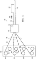
- the disclosed embodiments relate to a method and apparatus for producing a composite filler 30 suitable for filling gaps 34 between composite members, such as, without limitation, a stringer 36 attached to a skin 38.
- the stringer 36 includes a hat section 40 joined to a pair of flanges 42 by a radius section 43 that results in gaps 34 that are generally triangular in cross sectional shape along the length of the stringer 36.
- the cross section of the gaps 34 may vary along the length of the gap 34, either in its area or in its shape, or both.
- This variance may be caused, for example and without limitation, by ply drop-offs, pad-ups, or joggles (not shown) in the skin 38, and/or curvatures in either the stringer 36 or the skin 38.
- the stringer 36 and skin 38 are merely illustrative of a wide range of joined structural members having variable gaps 34 that may require a filler 30 in order to improve structural performance.
- the filler 30 may comprise a plurality of laminated plies 44 of unidirectional fiber prepreg. As will be discussed later below in more detail, the fiber orientations of the plies 44 may be the same or different, according to a predetermined ply schedule suitable for the application.
- the filler 30 has a generally triangular cross sectional shape 32 formed by three sides 46. Other cross sectional shapes 32 are possible.
- FIG. 4 illustrates a filler 30 having a substantially flat side 46 and two radiused sides 46a. The filler 30 shown in FIG.
- the cross sectional shapes of the fillers 30 shown in FIGS. 1 and 4 are merely illustrative of a wide range of cross sectional shapes that are possible.
- the cross sectional shape of filler 30 may have any number of straight sides, curves or a combination of curves and straight sides which may vary in area or geometry along the length of the filler 30, and which may correspond to the changing cross sectional profile of the gap 34 along its length.
- a filler 30 having a cross sectional shape formed by straight sides at one end of the filler 30 may transition either linearly or non-linearly, into a cross sectional shape having one or more curves at any point along the length of the filler 30.
- the cross section of the filler 30 may vary along its length.
- the cross sectional shape 32 and/or the cross sectional area 58 of the filler 30 may vary continuously or along only portions of the length of the filler 30.
- the cross sectional shape 32 remains the same, i.e. remains triangular, throughout the length of the filler, however the height H and width W 1 , and thus the area of the cross section varies.
- the cross sectional area 58 at one end 48 increases steadily at 54 to an intermediate section 52 where the cross sectional area 58 remains substantially constant, but then steadily decreases at 56 to the other end 50.
- the cross sectional area 58 of the filler 30 is greatest and remains substantially constant throughout the intermediate section 52, but varies linearly throughout sections 54 and 56. As previously stated, the cross sectional area 58 may vary at any rate of increase or decrease, or remain constant at any section along the length of the filler 30.
- apparatus generally indicated at 55 for producing a composite filler 30 broadly comprises a source 60 of pre-plied fiber reinforced strips 84, hereinafter referred to ply strips or reinforced strips 84 are pulled through a delivery head 62 by a puller 64.
- the delivery head 62 includes a ply strip guide 66 that directs the ply strips 84 through cut/add heads 68 into an ordered ply stack 92.
- At least one forming die 70 is employed to form the ply strip stack 92 into a filler 30 having the desired cross sectional shape and/or size along its length.
- the ply strip stack 92 may be directed by the guide 66 through more than one forming die 70.
- the cut/add heads 68 are operated by control signals issued by the controller 72 ( FIG. 7 ) and may comprise devices similar to those described in US Patent Number 4,699,683, issued October 13, 1987 , US Patent Number 7,213,629 issued May 8, 2007 and US Patent Publication No. 20070029030A1 published February 8, 2007 , the entire contents of which are incorporated by reference herein.
- the ply strip source 60 may comprise a composite ply layup 74 ( FIG. 9 ) that is slit into individual ply strips 84 ( FIG. 10 ) either before or after entering the delivery head 62.
- the prep-plied layup 74 may be slit into the ply strips 84 using any suitable cutting device, such as for example and without limitation, a Gerber cutter.
- the ply strip source 60 along with the cut/add heads 68, forming die 70 and puller 64 may be operated by a controller 72 which may comprise a PC or a PLC (programmable logic controller) that outputs control signals on lines 73.
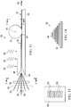
- the filler 30 may be formed from a ply layup 74 comprising a plurality of plies 76 of unidirectional fiber prepreg that are assembled ply-by-ply, according to a predetermined supply schedule (not shown), using either hand-layup techniques or an AFP (automatic fiber placement) machine (not shown).
- the fiber orientation of the plies 76 may vary from ply-to-ply.
- the plies 76 may have a 0 degree fiber orientation 78, a 45 degree fiber orientation 80, or a 90 degree fiber orientation 82, as well as other orientations within a particular layup 74.
- the ply layup may include plies having at least two types for fiber reinforcing fibers, such as glass fibers and carbon fibers, in order to fabricate fillers 30 known as "hybrid fillers". Other fiber reinforcements are possible.
- the ply layup 74 ( FIG. 9 ) is slit into a plurality of ply strips 84 as shown in FIG. 10 , each comprising one or more individual plies 76 of the same or differing fiber orientations.
- the ply strips 84 may vary in width W 2 , depending upon the cross sectional shape of the filler 30 being fabricated.
- the ply strip source 60 comprises a plurality of creels 86 respectively wound with ply strips 84 that may be of differing widths W 2 ( FIG. 10 ).
- a set of take-up reels 88 are provided to take up backing paper 85 that is removed from the ply strips 84 as they are dispensed from the creels 86.
- the ply strips 84 dispensed from the creels 86 are aligned with each other and fed as a group 90 to a delivery head 62 where the ply strips 84 are guided into a stack 92 ( FIG.
- the stack 92 may formed into the final cross sectional shape using more than one of the dies 70.
- the stack 92 is moved through the delivery head 62 by a suitable motorized puller 64 which pulls the formed filler 30 in the direction shown by the arrow 65 over a flat lower die 94, causing the ply strips 84 to be drawn from the creels 86. Operation of the puller 64 is controlled by the controller 72 shown in FIG. 7 .
- the process of pulling the stack 92 through the delivery head and drawing ply strips 84 from the creels 86 is carried out substantially continuously and automatically until the desired length of the filler 30 is completed.
- the operation of the creels 86 may be controlled by control signals from the controller 72 shown in FIG. 7 .
- FIG. 12 illustrates additional details of the apparatus 55 shown in FIG. 11 .
- the ply strips 84 dispensed from creels 86 respectively pass through cut/add heads 68 which cut and add ply strips 84 as required, to the lengths needed to produce a filler 30 of a desired length.
- the ply strips 84 pass, as a group 90, through a guide 66 shown in FIGS. 12 and 13 which includes a plurality of aligned slots 100.
- the slots 100 align the ply strips 84 and guide them into a chute 96 that may be heated by any suitable means at 98.
- the chute 96 funnels the aligned ply strips 84 into an ordered stack 92 shown in FIG.
- the chute 96 also heats the stack 92 to a forming temperature and guides the stack 92 into a nip 97 between the forming die 70 and flat lower die 94, drawn by the force applied to the stack 92 by the puller 64 ( FIG. 11 ) as the puller 64 pulls the completed filler 30 in the direction shown by the arrow 65.
- the lower die 94 may or may not form an extension of the heated chute 96.
- the die 70 may be driven to rotate by a motor (not shown) operated by the controller 72 shown in FIG. 7 which synchronizes the rotation of the die 70 with the speed of the puller 64. As previously noted, more than one die 70 may be employed in series to form the stack 92 into the desired cross sectional shape.
- the forming die 70 is generally circular about a central axis of rotation 95.
- the die 70 includes a concave die cavity 104 ( FIG. 15 ) formed by a peripheral die face 102.
- the die cavity 104 is generally triangular in cross sectional shape, and has a depth D 1 and a width W 3 that vary around the circumference of the die 70.
- the cross section of the die face 102 in contact with the stack 92 of ply strips 84 may vary as the die 70 rotates and the stack 92 moves through the die 70.
- FIG. 16 schematically illustrates the varying cross section profile of the die cavity 104, represented by the change in depth D 1 around the circumference of the die 70.
- the cross sectional profile of the die cavity 104 substantially corresponds to the cross sectional shape of the filler 30 shown in FIGS. 5 and 6 .
- the die cavity 104 may have any of a variety of other cross sectional shapes that vary around the circumference of the die 70, depending on the geometry of the filler 30 being fabricated.
- the controller 72 FIG. 7 ) controls the rotational position of the die 70 and synchronizes the die's rotational position with the rate at which the puller ( FIGS.
- Adhesive is applied to filler 30 using the apparatus 55a shown in FIG. 17 that includes an adhesive dispenser. Adhesive film strips 112 are dispensed from a pair of reels 114 and applied to the exterior sides 46 ( FIG. 3 ) of the filler 30 using a rotating cam 116.
- Cam 116 has a variable cross section cam face substantially matching that of the just-formed filler 30 and functions, along with a flat lower die 94, to press the adhesive film strips 112 onto the sides 46 of the filler 30 as the filler 30 and the film strips 112 pass between the cam 116 and the flat lower die 94.
- FIG. 18 illustrates the overall steps of a method of producing the filler 30 using the previously described apparatus 55.
- a stack 92 of prepreg ply strips 84 is formed, and at 120, the stack 92 of ply strips 84 is fed through one or more forming dies 70.
- the forming die 70 is used to form the stack 92 of ply strips 84, including varying the shape of the die face 102 as the stack 92 is being fed through the die 70.
- FIG. 18A broadly illustrates the steps of an alternate method of producing the filler 30 using the apparatus 55.
- a multi-ply layup 74 of fiber prepreg is assembled, in which the plies may have differing fiber orientations determined by a predetermined ply schedule.
- the layup 74 is slit into individual ply strip 84 having varying widths which are related to the cross sectional shape of the particular filler 30 being fabricated.
- the slit ply strips are arranged into a ordered stack 92 according to their widths, such that the stack 92 may have a cross sectional shape that approximates the final cross section shape of the filler 30 (see FIG. 14 ).
- the ordered stack 92 of ply strips 84 is fed to one or more forming dies 70 at step 131, and at 133, the forming die(s) 70 is used to form the stack 92 into a filler 30 having the desired cross sectional shape, which may vary along the length of the filler 30.
- FIG. 19 illustrates additional steps of one practical implementation of the method shown in FIG 18 .
- the geometry of the filler 30 is digitally defined and the materials from which the filler 30 is made are selected.
- a program is developed for producing the filler 30 and at 130 the program is post processed.
- the program is loaded into the apparatus 55, which includes programming the controller 72.
- the materials from which the filler 30 is formed are prepared, which includes assembling a ply layup 74.
- the ply layup 74 is slit into multiple ply strips 84 of the desired widths.
- the ply strips 84 are respectively loaded onto creels 86, and at 140, the ply strips 84 are fed through the delivery head 62 of the apparatus 55. At 142, the ends of the ply strips 84 are attached to the puller 64 and at 144 the heaters are turned on the heat the chute 96. At 146, the controller 72 runs the part program to form the filler 30, and at 146 the filler 30 may be trimmed to final length, as required. Finally, at 150, the filler 30 may be frozen for future use or, alternatively, transferred directly to a composite layup assembly (not shown) for use in filling a gap.
- FIGS. 20 and 21 illustrates another embodiment of the apparatus 55b.
- an assembled, multi-ply layup 74 is fed in the direction 152 to a slitter/laminator machine 154 that includes one or more forming dies 70 that may be similar to that previously described.
- the layup 74 may include one or more plies of unidirectional fiber prepreg of the same or differing fiber orientations, and may include one of more plies of an adhesive.
- a puller 64 is used to pull the layup 74 through the machine 154.
- Machine 154, as well as the puller 64 are operated by a suitable controller 72.
- the machine 154 broadly comprises a pair of nip rollers 156, a slitter 158, redirect rollers 162, 164, compaction rollers 166 and forming die 70.
- An assembled (pre-plied) layup 74 is fed into the nip rollers 156 which pull the layup 74 into the slitter 158.
- the slitter 158 comprises a plurality of spaced apart cutter blades 160 which are spaced apart from each other at differing distances and slit the layup 74 into a plurality of side-by-side, individual strips 84 of varying, preselected widths, each comprising one or more composite plies.
- the redirect rollers 162, 164 function to turn the side-by-side strips 84 ninety degrees, redirecting the strips 84 into alignment with each other and into a stack 92 that is compacted by rollers 166 and fed through one or more forming dies 70 (only one being illustrated in FIG. 21 ).
- the forming die 70 may be similar to the rotatable forming die 70 previously described having a peripheral die cavity 104 ( FIG. 15 ) that may or may or may not vary in shape and/or area around the circumference of the die 70.
- the die 70 may comprise one or more suitable type of stationary extrusion dies, rather that a rotatable forming die 70 of the type shown in FIGS. 12 , 15 and 15A .
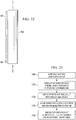
- FIG. 23 illustrates the overall steps of a method of producing a filler using the apparatus 55b shown in FIGS. 20-22 .
- a multi-ply composite layup 74 is assembled, and at 170, the layup 74 is fed substantially continuously through a slitter 158 and a forming die 70.
- the slitter 158 is used to slit the layup 74 into a plurality of side-by-side ply strips 84.
- the ply strips 84 are aligned into a stack 92 as the strips 84 are being fed from the slitter 158 to the die 70.
- the die 70 is used to form the stack 92 of ply strips 84 into a filler 30 of the desired cross sectional shape and area.
- FIG. 24 illustrates additional details of the method shown in FIG. 23 .
- the geometry of the filler 30 is digitally defined and the materials used to produce the filler 30 are selected.
- a program is generated for controlling the machine 154, and at 182 the program is loaded into the machine controller 72.
- a layup 74 is assembled and placed on a flat tape layer.
- the layup 74 is fed into the slitter 158 and at 188 the slit ply stack 92 is attached to the puller 64.
- heaters, if used in the machine 154 to preheat the layup 74 are pre-heated.
- the program is run which controls operation of the machine 154 to produce the filler 30.
- the filler 30 is trimmed to length and at 196, the filler 30 may be either frozen for future use, or transferred directly to a composite layup assembly for use in filling a gap.
- FIG. 25 illustrates the sequential operations performed by the machine 154.
- the assembled ply layup enters the machine 154.
- the nip rollers 156 pull the layup 74 into the machine 154 and at 222, the slitter 158 slits the layup 74 into multiple ply strips 84 of the desired width.
- redirect rollers 162 turn the strips 84 ninety degrees, and at 226 redirect rollers 164 bring the strips 84 together into a stack 92.
- the compaction rollers 166 compact the stack 92.
- a die 70 which may be stationary or movable as previously described, shapes the stack 92 into the desired filler shape. The filler exits the machine at 232.
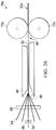
- FIGS. 26 and 28 illustrate still another embodiment of the apparatus 55c that may be employed to produce a filler 30a of the type shown in FIG. 27 .
- the filler 30a includes upper and lower portions 236, 238 having different cross sectional shapes that vary in area or geometry along their respective lengths.
- a pair of rotatable dies 70a, 70b are used to form the upper and lower portions 236, 238 respectively of the filler 30a.
- a puller such as the puller 64 shown in FIG. 11 , 20 and 21 , pulls the ply stack 92 into a nip 99 between the dies 70a, 70b. As best seen in FIG.
- the upper die 70a has a die cavity 104 having a generally triangular shape that varies in area around the circumference of the die 70a.
- Die 70b has a generally semi-circular die cavity 104a that likewise varies in cross sectional area around the circumference of the die 70b.
- the cross sectional shapes of the dies 70a, 70b shown in FIG. 28 are merely illustrative of a wide range of cross sectional geometries that are possible, including but not limited to those as discussed earlier with reference to the die 70 shown in FIGS. 12 and 15 .
- Embodiments of the disclosure may find use in a variety of potential applications, particularly in the transportation industry, including for example, aerospace, marine, automotive applications and other application where automated layup equipment may be used.
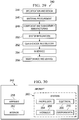
- embodiments of the disclosure may be used in the context of an aircraft manufacturing and service method 240 as shown in Figure 29 and an aircraft 242 as shown in Figure 30 .
- Aircraft applications of the disclosed embodiments may include, for example, without limitation, layup of stiffener members such as, without limitation beams, spars and stringers, to name only a few.
- exemplary method 240 may include specification and design 244 of the aircraft 242 and material procurement 246.
- component and subassembly manufacturing 248 and system integration 250 of the aircraft 242 takes place. Thereafter, the aircraft 242 may go through certification and delivery 252 in order to be placed in service 254. While in service by a customer, the aircraft 242 is scheduled for routine maintenance and service 256, which may also include modification, reconfiguration, refurbishment, and so on.
- Each of the processes of method 240 may be performed or carried out by a system integrator, a third party, and/or an operator (e.g., a customer).
- a system integrator may include without limitation any number of aircraft manufacturers and major-system subcontractors
- a third party may include without limitation any number of vendors, subcontractors, and suppliers
- an operator may be an airline, leasing company, military entity, service organization, and so on.
- the aircraft 242 produced by exemplary method 240 may include an airframe 258 with a plurality of systems 260 and an interior 262.
- high-level systems 260 include one or more of a propulsion system 264, an electrical system 266, a hydraulic system 268, and an environmental system 270. Any number of other systems may be included.
- an aerospace example is shown, the principles of the disclosure may be applied to other industries, such as the marine and automotive industries.
- Systems and methods embodied herein may be employed during any one or more of the stages of the production and service method 240.
- components or subassemblies corresponding to production process 248 may be fabricated or manufactured in a manner similar to components or subassemblies produced while the aircraft 242 is in service.
- one or more apparatus embodiments, method embodiments, or a combination thereof may be utilized during the production stages 248 and 250, for example, by substantially expediting assembly of or reducing the cost of an aircraft 242.
- apparatus embodiments, method embodiments, or a combination thereof may be utilized while the aircraft 242 is in service, for example and without limitation, to maintenance and service 256.
Description
- The present disclosure generally relates to the fabrication composite structures, and deals more particularly with a method for producing fillers used to fill gaps in such structures.
- Composite structures may be fabricated by joining two or more members together. In some cases, there may be one or more gaps in areas of joints between the members that may reduce the strength of the joints. In order to strengthen the joints, the gaps are filled with fillers, sometimes also referred to as radius fillers, fillets or noodles. The filler may be formed from composite materials such as adhesive, prepreg tape or fabric. In some cases, the cross section of the gap may vary in size and/or shape along its length as a result of the adjoining composite members converging or diverging from each other. For example, ply pad-ups, ply drop-offs and/or joggles on a composite skin may result in a variable gap between the skin and an overlying stiffener, such as a stringer, that is attached to the skin.
- In the past, fillers having variable cross sectional shapes were fabricated using hand layup techniques that involved laminating unidirectional fiber prepreg tape, in which the fiber orientation was parallel to the length of the gap. This hand layup technique required multiple processing steps, was labor intensive and time consuming. Additionally, fillers employing unidirectional fiber reinforcement may be subject to movement and may not exhibit the desired degree of resistance to cracking.
-
US 4,440,593 describes an apparatus for producing arcuately shaped filament containing reinforced plastic composite articles which have a non-constant cross-sectional shape over their length. The apparatus comprises a die having a die channel of non-constant cross-sectional shape. The die channel is formed by a pair of first and second die-forming members. One of the die-forming members may move relative to the other or both may move together at a constant speed in order to effectively pultrude a reinforced plastic composite article. -
US 4,559,005 describes a machine for forming preimpregnated composite material into thin, narrow structural elements. The machine includes a cylindrical lower forming roll and a cylindrical upper forming roll, which is urged into frictional contact with the lower forming roll. Annular protrusions are formed in the periphery of the lower forming roll, wherein each protrusion comprises a groove that defines a die. The die, with the outer surface of the upper forming roll, combine to form an orifice that is shaped substantially identical to the cross sectional shape of the structural elements. A strip of composite material is fed into a selected orifice. The rotating lower and upper forming rolls cause the strip of composite material to be drawn from its supply source and to be compacted, while in the orifice, into a structural element. -
US 2010/0024966 discloses a method according to the preamble ofclaim 1 and apparatus for producing solid profiles from a strip of fiber preimpregnated with resin. The method includes the steps of: providing a planar strip of fiber preimpregnated with resin which has a longitudinal direction and a transverse direction; corrugating the planar strip to form a corrugated strip with a plurality of zigzag folds parallel to the longitudinal direction; and compacting the corrugated strip in the transverse direction in order to place in contact and to join, one to the other, surfaces of the plurality of folds in order to form a solid profile. - Accordingly, there is a need for a method for producing a composite filler having a variable cross section along its length, that are reliable and repeatable, and which reduce labor costs by automating the fabrication process. There is also a need for a method as described above which result in a filler having improved stiffness, toughness and/or resistance to cracking.
- The disclosed embodiments provide a method for producing a composite filler having improved toughness and strength, and which reduces the time and labor required to produce a filler having varying cross section along its length. Improved filler toughness and strength are achieved by laminating plies of fiber prepreg in which the laminated plies have varying fiber orientations. The method may be carried out by automated equipment that produces laminated fillers of a desired length and varying cross sectional shape and/or area. An adhesive may be automatically applied to the outer surfaces of the filler, without the need for hand labor. Composite fillers may be produced more quickly and with more repeatable results, using fewer processing steps.
- An apparatus may be provided for producing a composite filler comprising a rotatable die and a device for moving a stack of reinforced strips through the die. The die has a peripheral die face adapted for forming a stack of strips into a desired cross sectional shape. The cross section of the die varies around its periphery. The device for pulling the stack of strips through the die comprises a puller. The apparatus may further comprise a plurality of creels each adapted to hold and dispense one of the strips, and a guide for directing the strips dispensed from the creels into a stack. The guide may include a plurality of aligned slots for respectively guiding the strips into the stack. The apparatus may further comprise a cut and add device for cutting the strips dispensed from the creels and selectively adding strips dispensed to the guide. The apparatus may also comprise a heated chute for guiding and heating the stack of strips that are formed by the die. The die may be substantially circular in shape and rotates about a central axis. The die face may include at least a first circumferential section having a substantially constant cross sectional area, and a second circumferential section having a varying cross sectional area. The apparatus may further comprise a slitter for slitting a layup of prepreg plies into a plurality of prepreg strips, and a redirect device for redirecting the cut prepreg strips into stacked relationship.
- An apparatus may be provided for producing a composite filler, comprising a slitter adapted to slit a multi-ply composite layup into a plurality of side-by-side strips, and a redirect device for redirecting the side-by-side strips into a stack. The apparatus further comprises a forming die for forming the stack of
composite strips into a desired cross sectional shape, and a puller for pulling the stack substantially continuously through the slitter, the redirect device and the forming die. The redirect device may include rollers for changing the orientation of the composite prepreg strips relative to each other. The forming die is rotatable and includes a substantially circular die face having a variable cross section around its periphery. - A method is provided of fabricating a composite filler having a cross section that varies along its length. The method comprises forming a stack of composite prepreg strips, feeding the stack of strips through at least one die, and using the die to form the stack of strips, including varying the shape of the face of the die in contact with the stack as the stack is fed through the die. Varying the shape of the die face includes rotating the die as the stack is fed through the die. Forming the stack of strips includes dispensing strips of composite prepreg respectively from a plurality of creels and aligning the strips with each other into a stack. The method may further comprise forming a multi-ply composite layup, feeding the layup substantially continuously through a slitter and at least one forming die, and using the slitter to slit the layup into a plurality of side-by-side composite prepreg strips. The method further comprises aligning the composite prepreg strips into a stack as the composite prepreg strips are fed from the slitter to the forming die, and using the die to form the stack of composite strips into the filler. Forming the layup may include laying up unidirectional fiber prepreg plies having at least two different fiber orientations.
- According to one aspect there may be provided a apparatus for producing a composite filler, including at least one rotatable die having a peripheral die face adapted for forming a stack of composite reinforced strips into a desired cross sectional shape, wherein the die face varies in cross sectional shape around the periphery of the die; and a device for moving the stack of reinforced strips through the die. The apparatus further includes at least one adhesive dispenser for dispensing an adhesive, and a device for pressing the dispensed adhesive onto the formed stack of reinforced strips.
- Advantageously the apparatus wherein the die includes a puller for pulling the stack through the die; and the strips are fiber prepreg.
- Advantageously the apparatus further including a plurality of creels each adapted to hold and dispense one of the reinforced strips; and a guide for directing the reinforced strips dispensed from the creels into a stack.
- Advantageously the apparatus wherein the guide includes a plurality of aligned slots for respectively guiding the reinforced strips into the stack.
- Advantageously the apparatus further comprising a cut and add device for cutting the reinforced strips dispensed from the creels and selectively adding reinforced strips dispensed to the guide.
- Advantageously the apparatus wherein the reinforced strips are a prepreg, and the apparatus further comprises a plurality of take-up reels adapted for taking up backing paper respectively on the strips of prepreg as the prepreg strips are dispensed from the creels.
- Advantageously the apparatus wherein further including a chute for guiding the stack of reinforced strips into the die.
- Advantageously the apparatus wherein the chute is a heated chute.
- Advantageously the apparatus wherein the die is substantially circular and has a central axis about which the die rotates.
- Advantageously the apparatus wherein the cross sectional shape of the die face is substantially V-shaped.
- Advantageously the apparatus further comprising a surface forming a nip into which the stack of reinforced strips may be fed and against which the die squeezes the stack of reinforced strips.
- Advantageously the apparatus wherein the die is substantially circular and the die face extends around at least a portion of the entire circumference of the die.
- Advantageously the apparatus wherein the die is substantially circular; and the die face varies in cross sectional area substantially continuously around the circumference of the die.
- Advantageously the apparatus wherein the die is substantially circular; and the die face includes at least a first circumferential section having a substantially constant cross sectional area, and at least a second circumferential section having a varying cross sectional area.
- Advantageously the apparatus wherein the die forms a first cross section of the stack of reinforced strips, and the apparatus further including a second die having a peripheral die face adapted for forming a second cross section of the stack of reinforced strips, wherein the die face of the second die varies in cross sectional shape around the periphery of the second die.
- Advantageously the device for pressing the dispensed adhesive onto the formed stack of reinforced strips includes a cam face with a cross sectional area that varies around the periphery of the device.
- Advantageously the apparatus wherein the dispenser includes a reel adapted to hold adhesive strips; and the reel dispenses the adhesive strips onto the formed stack of reinforced strips before the cam presses the adhesive onto the formed stack.
- Advantageously the apparatus further including a slitter for slitting a layup of prepreg plies into a plurality strips; and a redirect device for redirecting the cut prepreg strips into stacked relationship.
- Advantageously the apparatus further including a controller for synchronizing the rotation of the die with the operation of the device for moving the stack through the die.
- According to another aspect there may be provided an apparatus for producing a composite filler, including a slitter adapted to slit a multi-ply composite layup into a plurality of side-by-side strips; a redirect device for redirecting the side-by-side
strips into a stack; a forming die for forming the stack of composite strips into a desired cross sectional shape; and a puller for pulling the composite layup through the slitter, the redirect device and the forming die. - Advantageously the apparatus wherein the redirect device includes rollers for changing the orientation of the strips relative to each other.
- Advantageously the apparatus wherein forming die is disposed between the puller and the slitter.
- Advantageously the apparatus wherein the forming die is rotatable and includes a substantially circular die face having a variable cross section around its periphery.
- Advantageously the apparatus wherein the redirect device includes rollers through which the side-by-side strips are fed.
- Advantageously the apparatus further including a set of compaction rollers for compacting the stack of strips.
- Advantageously the apparatus wherein the slitter includes a plurality of cutters spaced apart at differing distances to slit the layup into strips of differing widths.
- Advantageously the apparatus further including a heated chute into which the stack may be fed from the slitter and heated to a forming temperature.
- Advantageously the apparatus further including at least one adhesive dispenser for dispensing an adhesive; and a cam for pressing the dispensed adhesive onto the formed stack of strips, the cam including a cam face having a cross sectional area that varies around the periphery of the cam.
- According to an aspect of the invention there is provided a method of fabricating a composite filler having a cross section that varies along its length, including forming a stack of composite prepreg strips; feeding the stack of strips through a die; and
using the die to form the stack of strips, including varying the shape of a die face in contact with the stack of strips as the stack is fed through the die. The method further includes applying a strip of adhesive to the formed stack of prepreg strips; and compressing the adhesive against the formed stack by rolling a cam over the formed stack having a varying cross section that matches the varying cross-section of the formed stack. - Advantageously the method wherein varying the shape of the die face includes rotating the die as the stack is fed through the die.
- Advantageously the method further including synchronizing the feeding of the stack through the die with the varying of the shape of the die in contact with the stack.
- Advantageously the method wherein forming the stack of strips includes dispensing strips of composite prepreg respectively from a plurality of creels; and aligning the strips with each other.
- Advantageously the method wherein aligning the strips is performed by passing the strips through a guide; and forming the strips further includes compacting the aligned strips into a stack.
- Advantageously the method further including heating the stack of strips to a forming temperature by passing the stack through a heated chute.
- Advantageously the method wherein forming the stack of prepreg strips includes forming a layup of prepreg plies; and slitting the layup into a plurality of strips of varying widths.
- Advantageously the method wherein forming the stack of prepreg strips further includes loading the slit strips respectively onto a plurality of creels dispensing the strips from the creels; and aligning the dispensed strips.
- Advantageously the method wherein forming the stack includes ordering the strips as they are being dispensed and aligned.
- Advantageously the method wherein feeding the stack through the die includes pulling one end of the stack.
- Advantageously the method wherein forming the stack of prepreg plies includes assembling a layup of prepreg plies; and slitting the layup into a plurality of side-by-side strips of varying widths by moving the layup through a slitter.
- Advantageously the method wherein forming the stack of prepreg plies includes redirecting the side-by-side slit strips into alignment with each other; and compacting the aligned strips into a stack.
- Advantageously the method wherein redirecting and compacting the strips are each performed by passing the strips through a set of rollers.
- Advantageously the method wherein assembling the layup includes laying up unidirectional fiber prepreg plies, including varying the fiber orientations of the plies of the layup.
- A composite filler produced by the method.
- According to a further aspect of the present invention there is provided a method of fabricating a composite filler, including forming a multi-ply composite layup; feeding the layup substantially continuously through a slitter and a forming die; using the slitter to slit the layup into a plurality of side-by-side composite prepreg strips; aligning the composite prepreg strips into a stack as the composite prepreg strips are fed from the slitter to the forming die; and using the die to form the stack of composite strips into the filler.
- Advantageously the method wherein forming the layup includes laying up unidirectional fiber prepreg plies having at least two differing fiber orientations.
- Advantageously the method wherein feeding the layup continuously is performed by pulling the one end of the stack of composite strips.
- Advantageously the method wherein aligning the composite prepreg strips is performed using rollers to redirect the strips after they have been slit from their side-by-side to a stacked relationship.
- Advantageously the method further including using rollers to compact the stack of composite strips before the stack is fed through the die.
- The novel features believed characteristic of the advantageous embodiments are set forth in the appended claims. The advantageous embodiments, however, as well as a preferred mode of use, further objectives and advantages thereof, will best be understood by reference to the following detailed description of an advantageous embodiment of the present disclosure when read in conjunction with the accompanying drawings, wherein:
-
FIG. 1 is an illustration of a perspective view of a composite filler. -
FIG. 2 is an illustration of a cross sectional, perspective view showing gaps between a stringer and a skin that may be filled with a composite filler. -
FIG. 3 is an illustration of an end view of the filler shown inFIG. 1 . -
FIG. 4 is an illustration of an end view of a filler having an alternate cross sectional shape. -
FIG. 4A is an illustration of a cross sectional view of a portion of three structural members of an I-beam being joined together and having a gap therebetween filled by the filler shown inFIG. 4 . -
FIG. 5 is an illustration of a perspective view of a filler having a cross sectional area that varies along its length. -
FIG. 6 is an illustration of an end view taken in a direction designated asFIG. 6 inFIG. 5 . -
FIG. 7 is an illustration of a functional block diagram of apparatus for producing the filler shown inFIGS. 5 and 6 . -
FIG. 8 is an illustration of an exploded, perspective view of a ply layup that may be used to fabricate a filler using the apparatus shown inFIG. 7 . -
FIG. 9 is an illustration of an end view of the ply layup shown inFIG.8 . -
FIG. 10 is an illustration of an end view showing the ply layup ofFIG.9 having been slit into individual prepreg strips. -
FIG. 11 is an illustration of a diagrammatic, side view of one embodiment of the apparatus shown inFIG. 7 . -
FIG. 12 is an illustration of a diagrammatic side view showing additional details of the apparatus shown inFIG. 11 . -
FIG. 13 is an illustration of a ply strip guide taken in the direction shown asFIG. 13 inFIG. 12 . -
FIG. 14 is an illustration of an end view of a stack of the ply strips, prior to being formed by the die. -
FIG. 15 is an illustration of an end view of the forming die taken in the direction shown asFIG. 15 inFIG. 12 . -
FIG. 15A is an illustration of a side view taken in the direction shown as 15A inFIG. 15 . -
FIG. 16 is a rectilinear layout of the circumference of the die shown inFIGS. 12 and15 , taken along the line 16-16. -
FIG. 17 is an illustration similar toFIG. 12 , showing the apparatus employing an adhesive applicator. -
FIG. 18 is an illustration of a flow diagram of a method of fabricating a composite filler having a cross section that varies along its length. -
FIG. 18A is an illustration of a flow diagram of an alternate method of fabricating a composite filler. -
FIG. 19 is an illustration of a flow diagram illustrating additional steps of the method shown inFIG. 18 . -
FIG. 20 is an illustration of a diagrammatic side view of an alternate form of the apparatus employing a ply slitter. -
FIG. 21 is an illustration of a plan view of the apparatus shown inFIG. 20 . -
FIG. 22 is an illustration of a sectional view taken along the line 22-22 inFIG. 21 . -
FIG. 23 is an illustration of a flow diagram of a method of fabricating a composite filler using the apparatus shown inFIGS. 20 and21 . -
FIG. 24 is an illustration of a flow diagram showing additional steps of the method shown inFIG. 23 . -
FIG. 25 is an illustration showing the sequential steps performed by the apparatus shown inFIGS. 20 and21 . -
FIG. 26 is a side view of an alternate embodiment of the apparatus employing a pair of forming dies. -
FIG. 27 is an illustration of a perspective view of a filler produced by the apparatus shown inFIG. 26 . -
FIG. 28 is an illustration of an end view of the forming dies shown inFIG.26 . -
FIG. 29 is an illustration of a flow diagram of aircraft production and service methodology. -
FIG. 30 is an illustration of a block diagram of an aircraft. - Referring first to
FIGS. 1-3 , the disclosed embodiments relate to a method and apparatus for producing acomposite filler 30 suitable for fillinggaps 34 between composite members, such as, without limitation, astringer 36 attached to askin 38. Thestringer 36 includes ahat section 40 joined to a pair offlanges 42 by aradius section 43 that results ingaps 34 that are generally triangular in cross sectional shape along the length of thestringer 36. In some applications, the cross section of thegaps 34 may vary along the length of thegap 34, either in its area or in its shape, or both. This variance may be caused, for example and without limitation, by ply drop-offs, pad-ups, or joggles (not shown) in theskin 38, and/or curvatures in either thestringer 36 or theskin 38. Thestringer 36 andskin 38 are merely illustrative of a wide range of joined structural members havingvariable gaps 34 that may require afiller 30 in order to improve structural performance. - Referring to
FIG. 3 , thefiller 30 may comprise a plurality oflaminated plies 44 of unidirectional fiber prepreg. As will be discussed later below in more detail, the fiber orientations of theplies 44 may be the same or different, according to a predetermined ply schedule suitable for the application. In the illustrated example, thefiller 30 has a generally triangular crosssectional shape 32 formed by threesides 46. Other crosssectional shapes 32 are possible. For example,FIG. 4 illustrates afiller 30 having a substantiallyflat side 46 and tworadiused sides 46a. Thefiller 30 shown inFIG. 4 may be suitable for use in filling agap 34 between a pair of back-to-back L or U-shaped shapedstructural members 35, and acap 37 that are joined together to form an I-Beam (only partially shown inFIG. 4A ). The cross sectional shapes of thefillers 30 shown inFIGS. 1 and4 are merely illustrative of a wide range of cross sectional shapes that are possible. For example, and without limitation, the cross sectional shape offiller 30 may have any number of straight sides, curves or a combination of curves and straight sides which may vary in area or geometry along the length of thefiller 30, and which may correspond to the changing cross sectional profile of thegap 34 along its length. Afiller 30 having a cross sectional shape formed by straight sides at one end of thefiller 30 may transition either linearly or non-linearly, into a cross sectional shape having one or more curves at any point along the length of thefiller 30. - Referring now to
FIGS. 5 and 6 , as previously discussed, in some applications the cross section of thefiller 30 may vary along its length. For example, the crosssectional shape 32 and/or the crosssectional area 58 of thefiller 30 may vary continuously or along only portions of the length of thefiller 30. In the example shown inFIGS. 5 and 6 , the crosssectional shape 32 remains the same, i.e. remains triangular, throughout the length of the filler, however the height H and width W1, and thus the area of the cross section varies. For example, the crosssectional area 58 at oneend 48 increases steadily at 54 to anintermediate section 52 where the crosssectional area 58 remains substantially constant, but then steadily decreases at 56 to theother end 50. The crosssectional area 58 of thefiller 30 is greatest and remains substantially constant throughout theintermediate section 52, but varies linearly throughoutsections sectional area 58 may vary at any rate of increase or decrease, or remain constant at any section along the length of thefiller 30. - Referring now to
FIG. 7 , apparatus generally indicated at 55 for producing acomposite filler 30 broadly comprises asource 60 of pre-plied fiber reinforcedstrips 84, hereinafter referred to ply strips or reinforcedstrips 84 are pulled through adelivery head 62 by apuller 64. Thedelivery head 62 includes aply strip guide 66 that directs the ply strips 84 through cut/add heads 68 into an orderedply stack 92. At least one formingdie 70 is employed to form theply strip stack 92 into afiller 30 having the desired cross sectional shape and/or size along its length. In some embodiments, theply strip stack 92 may be directed by theguide 66 through more than one formingdie 70. The cut/add heads 68 are operated by control signals issued by the controller 72 (FIG. 7 ) and may comprise devices similar to those described inUS Patent Number 4,699,683, issued October 13, 1987 ,US Patent Number 7,213,629 issued May 8, 2007 andUS Patent Publication No. 20070029030A1 published February 8, 2007 , the entire contents of which are incorporated by reference herein. In one embodiment, theply strip source 60 may comprise a composite ply layup 74 (FIG. 9 ) that is slit into individual ply strips 84 (FIG. 10 ) either before or after entering thedelivery head 62. The prep-pliedlayup 74 may be slit into the ply strips 84 using any suitable cutting device, such as for example and without limitation, a Gerber cutter. Theply strip source 60 along with the cut/add heads 68, formingdie 70 andpuller 64 may be operated by acontroller 72 which may comprise a PC or a PLC (programmable logic controller) that outputs control signals onlines 73. - Referring now to
FIGS. 8 ,9 and 10 , as previously mentioned, thefiller 30 may be formed from aply layup 74 comprising a plurality ofplies 76 of unidirectional fiber prepreg that are assembled ply-by-ply, according to a predetermined supply schedule (not shown), using either hand-layup techniques or an AFP (automatic fiber placement) machine (not shown). The fiber orientation of theplies 76 may vary from ply-to-ply. For example, as shown inFIG. 8 , theplies 76 may have a 0degree fiber orientation 78, a 45degree fiber orientation 80, or a 90degree fiber orientation 82, as well as other orientations within aparticular layup 74. The ply layup may include plies having at least two types for fiber reinforcing fibers, such as glass fibers and carbon fibers, in order to fabricatefillers 30 known as "hybrid fillers". Other fiber reinforcements are possible. Following assembly, the ply layup 74 (FIG. 9 ) is slit into a plurality of ply strips 84 as shown inFIG. 10 , each comprising one or more individual plies 76 of the same or differing fiber orientations. The ply strips 84 may vary in width W2, depending upon the cross sectional shape of thefiller 30 being fabricated. - Attention is now directed to
FIG. 11 which broadly illustrates components of one embodiment of theapparatus 55. In this example, theply strip source 60 comprises a plurality ofcreels 86 respectively wound withply strips 84 that may be of differing widths W2 (FIG. 10 ). A set of take-upreels 88 are provided to take up backingpaper 85 that is removed from the ply strips 84 as they are dispensed from thecreels 86. The ply strips 84 dispensed from thecreels 86 are aligned with each other and fed as agroup 90 to adelivery head 62 where the ply strips 84 are guided into a stack 92 (FIG. 14 ) that is heated to a forming temperature and formed by at least one die 70 into the final cross sectional shape of thefiller 30. As previously mentioned, in some embodiments, thestack 92 may formed into the final cross sectional shape using more than one of the dies 70. Thestack 92 is moved through thedelivery head 62 by a suitablemotorized puller 64 which pulls the formedfiller 30 in the direction shown by thearrow 65 over a flatlower die 94, causing the ply strips 84 to be drawn from thecreels 86. Operation of thepuller 64 is controlled by thecontroller 72 shown inFIG. 7 . The process of pulling thestack 92 through the delivery head and drawing ply strips 84 from thecreels 86 is carried out substantially continuously and automatically until the desired length of thefiller 30 is completed. In some embodiments, the operation of thecreels 86 may be controlled by control signals from thecontroller 72 shown inFIG. 7 . -
FIG. 12 illustrates additional details of theapparatus 55 shown inFIG. 11 . The ply strips 84 dispensed fromcreels 86 respectively pass through cut/add heads 68 which cut and addply strips 84 as required, to the lengths needed to produce afiller 30 of a desired length. The ply strips 84 pass, as agroup 90, through aguide 66 shown inFIGS. 12 and 13 which includes a plurality of alignedslots 100. Theslots 100 align the ply strips 84 and guide them into achute 96 that may be heated by any suitable means at 98. Thechute 96 funnels the aligned ply strips 84 into an orderedstack 92 shown inFIG. 14 which has a cross section that roughly approximates the cross sectional shape and area of the completedfiller 30. Thechute 96 also heats thestack 92 to a forming temperature and guides thestack 92 into a nip 97 between the formingdie 70 and flatlower die 94, drawn by the force applied to thestack 92 by the puller 64 (FIG. 11 ) as thepuller 64 pulls the completedfiller 30 in the direction shown by thearrow 65. Thelower die 94 may or may not form an extension of theheated chute 96. The die 70 may be driven to rotate by a motor (not shown) operated by thecontroller 72 shown inFIG. 7 which synchronizes the rotation of the die 70 with the speed of thepuller 64. As previously noted, more than one die 70 may be employed in series to form thestack 92 into the desired cross sectional shape. - Referring now to
FIGS. 12 ,15, 15A and 16 , the formingdie 70 is generally circular about a central axis ofrotation 95. Thedie 70 includes a concave die cavity 104 (FIG. 15 ) formed by aperipheral die face 102. In the illustrated example, thedie cavity 104 is generally triangular in cross sectional shape, and has a depth D1 and a width W3 that vary around the circumference of thedie 70. Thus, the cross section of thedie face 102 in contact with thestack 92 of ply strips 84 may vary as thedie 70 rotates and thestack 92 moves through thedie 70.FIG. 16 schematically illustrates the varying cross section profile of thedie cavity 104, represented by the change in depth D1 around the circumference of thedie 70. The depth D1 increases steadily from a depth D1 at 106 to a depth D2 at 108 and then decreases to D1 at 110. As is apparent fromFIG. 16 , the cross sectional profile of thedie cavity 104 substantially corresponds to the cross sectional shape of thefiller 30 shown inFIGS. 5 and 6 . Thedie cavity 104 may have any of a variety of other cross sectional shapes that vary around the circumference of the die 70, depending on the geometry of thefiller 30 being fabricated. As previously mentioned, the controller 72 (FIG. 7 ) controls the rotational position of thedie 70 and synchronizes the die's rotational position with the rate at which the puller (FIGS. 7 and10 ) pulls thefiller 30 through the die 70 in order to vary thedie face 102 in contact with theply stack 92 as the ply stack passes into thenip 97. An adhesive is applied to outer surfaces of thefiller 30 which aids in bonding thefiller 30 to surrounding structural members forming thegap 34 shown inFIG. 2 , such as thestringer 36 and theskin 38. Adhesive is applied tofiller 30 using theapparatus 55a shown inFIG. 17 that includes an adhesive dispenser. Adhesive film strips 112 are dispensed from a pair ofreels 114 and applied to the exterior sides 46 (FIG. 3 ) of thefiller 30 using arotating cam 116.Cam 116 has a variable cross section cam face substantially matching that of the just-formedfiller 30 and functions, along with a flatlower die 94, to press the adhesive film strips 112 onto thesides 46 of thefiller 30 as thefiller 30 and the film strips 112 pass between thecam 116 and the flatlower die 94. -
FIG. 18 illustrates the overall steps of a method of producing thefiller 30 using the previously describedapparatus 55. Beginning atstep 118, astack 92 of prepreg ply strips 84 is formed, and at 120, thestack 92 of ply strips 84 is fed through one or more forming dies 70. At 124, the formingdie 70 is used to form thestack 92 of ply strips 84, including varying the shape of thedie face 102 as thestack 92 is being fed through thedie 70. -
FIG. 18A broadly illustrates the steps of an alternate method of producing thefiller 30 using theapparatus 55. Beginning atstep 125, amulti-ply layup 74 of fiber prepreg is assembled, in which the plies may have differing fiber orientations determined by a predetermined ply schedule. At 127, thelayup 74 is slit intoindividual ply strip 84 having varying widths which are related to the cross sectional shape of theparticular filler 30 being fabricated. Atstep 129, the slit ply strips are arranged into a orderedstack 92 according to their widths, such that thestack 92 may have a cross sectional shape that approximates the final cross section shape of the filler 30 (seeFIG. 14 ). The orderedstack 92 of ply strips 84 is fed to one or more forming dies 70 atstep 131, and at 133, the forming die(s) 70 is used to form thestack 92 into afiller 30 having the desired cross sectional shape, which may vary along the length of thefiller 30. -
FIG. 19 illustrates additional steps of one practical implementation of the method shown inFIG 18 . At 126, the geometry of thefiller 30 is digitally defined and the materials from which thefiller 30 is made are selected. Atstep 128, a program is developed for producing thefiller 30 and at 130 the program is post processed. Atstep 132, the program is loaded into theapparatus 55, which includes programming thecontroller 72. Atstep 134, the materials from which thefiller 30 is formed are prepared, which includes assembling aply layup 74. At 136, theply layup 74 is slit into multiple ply strips 84 of the desired widths. At 138, the ply strips 84 are respectively loaded ontocreels 86, and at 140, the ply strips 84 are fed through thedelivery head 62 of theapparatus 55. At 142, the ends of the ply strips 84 are attached to thepuller 64 and at 144 the heaters are turned on the heat thechute 96. At 146, thecontroller 72 runs the part program to form thefiller 30, and at 146 thefiller 30 may be trimmed to final length, as required. Finally, at 150, thefiller 30 may be frozen for future use or, alternatively, transferred directly to a composite layup assembly (not shown) for use in filling a gap. - Attention is now directed to
FIGS. 20 and21 which illustrates another embodiment of theapparatus 55b. In this embodiment, an assembled,multi-ply layup 74 is fed in thedirection 152 to a slitter/laminator machine 154 that includes one or more forming dies 70 that may be similar to that previously described. Thelayup 74 may include one or more plies of unidirectional fiber prepreg of the same or differing fiber orientations, and may include one of more plies of an adhesive. Apuller 64 is used to pull thelayup 74 through themachine 154.Machine 154, as well as thepuller 64 are operated by asuitable controller 72. - Referring now particularly to
FIGS. 21 and22 , themachine 154 broadly comprises a pair of niprollers 156, aslitter 158, redirectrollers compaction rollers 166 and formingdie 70. An assembled (pre-plied)layup 74 is fed into the niprollers 156 which pull thelayup 74 into theslitter 158. Theslitter 158 comprises a plurality of spaced apartcutter blades 160 which are spaced apart from each other at differing distances and slit thelayup 74 into a plurality of side-by-side,individual strips 84 of varying, preselected widths, each comprising one or more composite plies. Theredirect rollers side strips 84 ninety degrees, redirecting thestrips 84 into alignment with each other and into astack 92 that is compacted byrollers 166 and fed through one or more forming dies 70 (only one being illustrated inFIG. 21 ). The formingdie 70 may be similar to therotatable forming die 70 previously described having a peripheral die cavity 104 (FIG. 15 ) that may or may or may not vary in shape and/or area around the circumference of thedie 70. In other embodiments, thedie 70 may comprise one or more suitable type of stationary extrusion dies, rather that arotatable forming die 70 of the type shown inFIGS. 12 ,15 and 15A . -
FIG. 23 illustrates the overall steps of a method of producing a filler using theapparatus 55b shown inFIGS. 20-22 . Beginning atstep 168, a multi-plycomposite layup 74 is assembled, and at 170, thelayup 74 is fed substantially continuously through aslitter 158 and a formingdie 70. At 172, theslitter 158 is used to slit thelayup 74 into a plurality of side-by-side ply strips 84. At 174, the ply strips 84 are aligned into astack 92 as thestrips 84 are being fed from theslitter 158 to thedie 70. At 176, thedie 70 is used to form thestack 92 of ply strips 84 into afiller 30 of the desired cross sectional shape and area. -
FIG. 24 illustrates additional details of the method shown inFIG. 23 . At 178, the geometry of thefiller 30 is digitally defined and the materials used to produce thefiller 30 are selected. At 180 a program is generated for controlling themachine 154, and at 182 the program is loaded into themachine controller 72. At 184, alayup 74 is assembled and placed on a flat tape layer. At 186, thelayup 74 is fed into theslitter 158 and at 188 the slit plystack 92 is attached to thepuller 64. At 190, heaters, if used in themachine 154 to preheat thelayup 74, are pre-heated. At 192, the program is run which controls operation of themachine 154 to produce thefiller 30. At 194, thefiller 30 is trimmed to length and at 196, thefiller 30 may be either frozen for future use, or transferred directly to a composite layup assembly for use in filling a gap. -
FIG. 25 illustrates the sequential operations performed by themachine 154. Beginning at 198, the assembled ply layup enters themachine 154. The niprollers 156 pull thelayup 74 into themachine 154 and at 222, theslitter 158 slits thelayup 74 into multiple ply strips 84 of the desired width. At 224, redirectrollers 162 turn thestrips 84 ninety degrees, and at 226redirect rollers 164 bring thestrips 84 together into astack 92. At 228, thecompaction rollers 166 compact thestack 92. At 230, adie 70, which may be stationary or movable as previously described, shapes thestack 92 into the desired filler shape. The filler exits the machine at 232. -
FIGS. 26 and28 illustrate still another embodiment of theapparatus 55c that may be employed to produce afiller 30a of the type shown inFIG. 27 . In this example, thefiller 30a includes upper andlower portions lower portions filler 30a. A puller, such as thepuller 64 shown inFIG. 11 ,20 and21 , pulls theply stack 92 into a nip 99 between the dies 70a, 70b. As best seen inFIG. 28 , theupper die 70a has adie cavity 104 having a generally triangular shape that varies in area around the circumference of thedie 70a.Die 70b has a generallysemi-circular die cavity 104a that likewise varies in cross sectional area around the circumference of thedie 70b. The cross sectional shapes of the dies 70a, 70b shown inFIG. 28 are merely illustrative of a wide range of cross sectional geometries that are possible, including but not limited to those as discussed earlier with reference to the die 70 shown inFIGS. 12 and15 . - Embodiments of the disclosure may find use in a variety of potential applications, particularly in the transportation industry, including for example, aerospace, marine, automotive applications and other application where automated layup equipment may be used. Thus, referring now to
FIGS. 29 and 30 , embodiments of the disclosure may be used in the context of an aircraft manufacturing andservice method 240 as shown inFigure 29 and anaircraft 242 as shown inFigure 30 . Aircraft applications of the disclosed embodiments may include, for example, without limitation, layup of stiffener members such as, without limitation beams, spars and stringers, to name only a few. During pre-production,exemplary method 240 may include specification anddesign 244 of theaircraft 242 andmaterial procurement 246. During production, component andsubassembly manufacturing 248 andsystem integration 250 of theaircraft 242 takes place. Thereafter, theaircraft 242 may go through certification anddelivery 252 in order to be placed inservice 254. While in service by a customer, theaircraft 242 is scheduled for routine maintenance andservice 256, which may also include modification, reconfiguration, refurbishment, and so on. - Each of the processes of
method 240 may be performed or carried out by a system integrator, a third party, and/or an operator (e.g., a customer). For the purposes of this description, a system integrator may include without limitation any number of aircraft manufacturers and major-system subcontractors; a third party may include without limitation any number of vendors, subcontractors, and suppliers; and an operator may be an airline, leasing company, military entity, service organization, and so on. - As shown in
FIG. 30 , theaircraft 242 produced byexemplary method 240 may include anairframe 258 with a plurality ofsystems 260 and an interior 262. Examples of high-level systems 260 include one or more of apropulsion system 264, anelectrical system 266, ahydraulic system 268, and anenvironmental system 270. Any number of other systems may be included. Although an aerospace example is shown, the principles of the disclosure may be applied to other industries, such as the marine and automotive industries. - Systems and methods embodied herein may be employed during any one or more of the stages of the production and
service method 240. For example, components or subassemblies corresponding toproduction process 248 may be fabricated or manufactured in a manner similar to components or subassemblies produced while theaircraft 242 is in service. Also, one or more apparatus embodiments, method embodiments, or a combination thereof may be utilized during the production stages 248 and 250, for example, by substantially expediting assembly of or reducing the cost of anaircraft 242. Similarly, one or more of apparatus embodiments, method embodiments, or a combination thereof may be utilized while theaircraft 242 is in service, for example and without limitation, to maintenance andservice 256.
Claims (5)
- A method of fabricating a composite filler (30) having a cross section that varies along its length, comprising:forming (118) a stack (92) of composite prepreg strips;feeding (120) the stack (92) of strips (84) through a die (70); andusing (124) the die (70) to form the stack (92) of strips (84), including varying the shape of a die face (102) in contact with the stack (92) of strips (84) as the stack (92) is fed through the die (70);characterized in thatthe method further comprises:applying a strip of adhesive to the formed stack (92) of prepreg strips (84); andcompressing the adhesive against the formed stack (92) by rolling a cam over the formed stack (92) having a varying cross section that matches the varying cross section of the formed stack (92).
- The method of claim 1, further comprising:synchronizing the feeding of the stack (92) through the die (70) with the varying of the shape of the die (70) in contact with the stack (92).
- The method of claim 1, wherein forming the stack (92) of strips (84) includes:dispensing strips (84) of composite prepreg respectively from a plurality of creels (86); andaligning the strips (84) with each other.
- The method of claim 3, wherein:aligning the strips (84) is performed by passing the strips (84) through a guide (66); andforming the strips(84) further includes compacting the aligned strips (84) into a stack (92).
- The method of claim 1, wherein forming the stack of prepreg plies (84) includes:assembling a layup (74) of prepreg plies (84); and
slitting the layup (74) into a plurality of side-by-side strips of varying widths by moving the layup (74) through a slitter (154).
Applications Claiming Priority (1)
| Application Number | Priority Date | Filing Date | Title |
|---|---|---|---|
| US13/283,065 US8591685B2 (en) | 2011-10-27 | 2011-10-27 | Method and apparatus for producing composite fillers |
Publications (2)
| Publication Number | Publication Date |
|---|---|
| EP2586600A1 EP2586600A1 (en) | 2013-05-01 |
| EP2586600B1 true EP2586600B1 (en) | 2018-03-07 |
Family
ID=46832235
Family Applications (1)
| Application Number | Title | Priority Date | Filing Date |
|---|---|---|---|
| EP12182861.0A Active EP2586600B1 (en) | 2011-10-27 | 2012-09-04 | Method and apparatus for producing composite fillers |
Country Status (7)
| Country | Link |
|---|---|
| US (2) | US8591685B2 (en) |
| EP (1) | EP2586600B1 (en) |
| JP (1) | JP5988826B2 (en) |
| CN (1) | CN103085291B (en) |
| CA (1) | CA2792790C (en) |
| ES (1) | ES2672094T3 (en) |
| PT (1) | PT2586600T (en) |
Families Citing this family (42)
| Publication number | Priority date | Publication date | Assignee | Title |
|---|---|---|---|---|
| US9586699B1 (en) | 1999-08-16 | 2017-03-07 | Smart Drilling And Completion, Inc. | Methods and apparatus for monitoring and fixing holes in composite aircraft |
| US9625361B1 (en) | 2001-08-19 | 2017-04-18 | Smart Drilling And Completion, Inc. | Methods and apparatus to prevent failures of fiber-reinforced composite materials under compressive stresses caused by fluids and gases invading microfractures in the materials |
| US8591685B2 (en) | 2011-10-27 | 2013-11-26 | The Boeing Company | Method and apparatus for producing composite fillers |
| US9616594B2 (en) * | 2012-08-06 | 2017-04-11 | The Boeing Company | Radius fillers for composite structures, composite structures that include radius fillers, and systems and methods of forming the same |
| US9327470B1 (en) * | 2012-12-05 | 2016-05-03 | The Boeing Company | Variable-radius laminated radius filler and system and method for manufacturing same |
| US9855702B1 (en) | 2013-10-03 | 2018-01-02 | The Boeing Company | Method and apparatus for making composite fillers |
| US9415577B1 (en) | 2013-10-03 | 2016-08-16 | The Boeing Company | Automated fabrication of composite fillers |
| GB2522904B (en) * | 2014-02-10 | 2016-12-28 | Ge Aviat Systems Ltd | Method of making an airdam |
| US9566739B2 (en) | 2014-02-18 | 2017-02-14 | The Boeing Company | Composite filler |
| US10112349B2 (en) * | 2014-03-20 | 2018-10-30 | The Boeing Company | Placement of prepreg tows in high angle transition regions |
| EP2926983A1 (en) * | 2014-04-02 | 2015-10-07 | LM WP Patent Holding A/S | A method and apparatus for manufacturing a part of a wind turbine blade |
| US10035309B2 (en) | 2014-04-03 | 2018-07-31 | The Boeing Company | Radius fillers for composite structures, composite structures that include radius fillers, and systems and methods of forming the same |
| US10065366B2 (en) | 2014-05-27 | 2018-09-04 | The Boeing Company | Folded composite filler |
| US10040274B2 (en) | 2014-06-17 | 2018-08-07 | The Boeing Company | Pre-filled radius layups |
| US9475256B2 (en) * | 2014-07-10 | 2016-10-25 | The Boeing Company | Composite filler |
| US10105942B2 (en) | 2014-08-20 | 2018-10-23 | The Boeing Company | Systems and methods for forming radius fillers for composite structures |
| US9643395B2 (en) * | 2014-08-20 | 2017-05-09 | The Boeing Company | Systems and methods for forming radius fillers for composite structures |
| US10232572B2 (en) * | 2014-08-27 | 2019-03-19 | The Boeing Company | Composite filler forming apparatus |
| US9630376B2 (en) * | 2014-09-22 | 2017-04-25 | The Boeing Company | Composite filler |
| EP3040191B1 (en) * | 2014-12-30 | 2019-08-07 | Airbus Operations, S.L. | Method for manufacturing fillers of composite material |
| US10040537B2 (en) * | 2015-01-15 | 2018-08-07 | The Boeing Company | Laminate composite wing structures |
| US10513101B2 (en) * | 2015-03-13 | 2019-12-24 | The Boeing Company | Apparatuses and methods for creating layered tape composite structures |
| DE102015109855A1 (en) * | 2015-06-19 | 2016-12-22 | Airbus Operations Gmbh | Method for producing components, in particular elongated profiles from strip-shaped, pre-impregnated fibers (prepreg) |
| US9463864B1 (en) | 2015-07-28 | 2016-10-11 | The Boeing Company | Radius filler containing vertical ply stacks and thin plies |
| US20170029577A1 (en) * | 2015-07-29 | 2017-02-02 | The Boeing Company | Noodle Comprised of a Matrix of Discontinuous Filaments |
| JP7320945B2 (en) * | 2015-11-12 | 2023-08-04 | サイテック インダストリーズ インコーポレイテッド | Hybrid veil as an intermediate layer in composites |
| DE102016100335B3 (en) * | 2016-01-11 | 2017-05-11 | Deutsches Zentrum für Luft- und Raumfahrt e.V. | Method and device for producing a fiber gusset, and method and system for producing a T-shaped component segment with a fiber gusset |
| JP6667391B2 (en) * | 2016-07-06 | 2020-03-18 | 三菱重工業株式会社 | Composite material, pultrusion molding apparatus and pultrusion molding method |
| US10668683B2 (en) * | 2016-09-15 | 2020-06-02 | The Boeing Company | Gap fillers for composite materials |
| US10046525B2 (en) * | 2016-09-30 | 2018-08-14 | The Boeing Company | Advanced variable radius laminated composite radius filler |
| WO2018168202A1 (en) * | 2017-03-17 | 2018-09-20 | 株式会社Subaru | Shaping device for fiber material and shaping method for fiber material |
| US11065830B2 (en) | 2017-04-26 | 2021-07-20 | The Boeing Company | Pultrusion systems that apply lengthwise curvature to composite parts |
| US10703053B2 (en) * | 2017-07-06 | 2020-07-07 | The Boeing Company | Method and system for manufacturing noodles of structural joints |
| US10442153B2 (en) * | 2017-12-22 | 2019-10-15 | The Boeing Company | Stiffened stringer panel with integral indexing laminate stacks |
| DE102018002545A1 (en) | 2018-03-28 | 2019-10-02 | 9T Labs Ag | Method of cutting an extrudate |
| DE102018002544A1 (en) | 2018-03-28 | 2019-10-02 | 9T Labs Ag | Process for producing an extrudate |
| US20220063207A1 (en) * | 2018-12-20 | 2022-03-03 | Vestas Wind Systems A/S | Improvements relating to wind turbine blade manufacture |
| EP3950292A4 (en) * | 2019-03-29 | 2022-12-14 | Kawasaki Jukogyo Kabushiki Kaisha | Panel structure made of composite material and method for manufacturing same |
| US11254074B2 (en) * | 2019-06-19 | 2022-02-22 | The Boeing Company | Apparatus and method for making radius composite gap filler |
| US11529776B2 (en) * | 2019-08-01 | 2022-12-20 | The Boeing Company | Aircraft comprising composite structural component, and method for forming composite structural component |
| US11745442B2 (en) | 2019-08-22 | 2023-09-05 | The Boeing Company | Highly contoured composite structures and system and method for making the same |
| DE102020133805A1 (en) | 2020-12-16 | 2022-06-23 | Volkswagen Aktiengesellschaft | Method and process arrangement for the production of a fiber-reinforced plastic component |
Citations (1)
| Publication number | Priority date | Publication date | Assignee | Title |
|---|---|---|---|---|
| US20100024966A1 (en) * | 2006-04-25 | 2010-02-04 | Serra Soldadura, Sa | Method and apparatus for producing solid profiles from a strip of fiber preimpregnated with resin |
Family Cites Families (28)
| Publication number | Priority date | Publication date | Assignee | Title |
|---|---|---|---|---|
| US2977630A (en) * | 1956-11-26 | 1961-04-04 | Gen Electric | Production of continuous laminated strips |
| JPS57181826A (en) * | 1981-04-03 | 1982-11-09 | Furukawa Electric Co Ltd:The | Manufacture of fiber-reinforced plastic filament |
| US4410382A (en) * | 1981-10-30 | 1983-10-18 | Robert Varela | Telltale structure and method of producing same |
| US4440593A (en) | 1981-12-11 | 1984-04-03 | Goldsworthy Engineering, Inc. | Reinforced plastic composite articles and apparatus and method for producing same |
| US4469541A (en) * | 1981-12-11 | 1984-09-04 | Goldsworthy Engineering, Inc. | Method for forming reinforced plastic composite articles |
| US4559005A (en) | 1984-12-24 | 1985-12-17 | The Boeing Company | Machine for forming composite material into fillets |
| US4699683A (en) | 1986-02-07 | 1987-10-13 | The Boeing Company | Multiroving fiber laminator |
| US4789594A (en) | 1987-04-15 | 1988-12-06 | The Boeing Company | Method of forming composite radius fillers |
| US4778545A (en) | 1987-09-18 | 1988-10-18 | The Boeing Company | Method and apparatus for forming a fillet |
| US4992229A (en) | 1989-02-14 | 1991-02-12 | Phillips Petroleum Company | Thermoplastic re-pultrusion |
| US5132070A (en) * | 1990-08-17 | 1992-07-21 | Paul Marlene L | Process for the manufacture of composite parts |
| JP3021077B2 (en) * | 1991-03-28 | 2000-03-15 | 富士重工業株式会社 | Composite filler molding equipment |
| US5820804A (en) * | 1996-06-20 | 1998-10-13 | Elmaleh; Jon | Apparatus and method for shaping an elongated member |
| US6214263B1 (en) * | 1999-02-12 | 2001-04-10 | Chip Coolers, Inc. | Method of molding a reinforced article |
| US7118699B2 (en) * | 2001-03-05 | 2006-10-10 | Illinois Tool Works Inc. | Method of making a composite with a barrier layer in a closed mold process |
| US6787246B2 (en) * | 2001-10-05 | 2004-09-07 | Kreido Laboratories | Manufacture of flat surfaced composites comprising powdered fillers in a polymer matrix |
| US8211530B2 (en) | 2003-02-03 | 2012-07-03 | Northrop Grumman Systems Corporation | Adhesive fillets and method and apparatus for making same |
| US7213629B2 (en) | 2003-05-14 | 2007-05-08 | The Boeing Company | Vacuum assisted ply placement shoe and method |
| US7249943B2 (en) * | 2003-08-01 | 2007-07-31 | Alliant Techsystems Inc. | Apparatus for forming composite stiffeners and reinforcing structures |
| US7681615B2 (en) | 2005-08-04 | 2010-03-23 | The Boeing Company | Tow width adaptable placement head device and method |
| US7807005B2 (en) | 2006-02-02 | 2010-10-05 | The Boeing Company | Fabrication process for thermoplastic composite parts |
| JP5116282B2 (en) * | 2006-10-31 | 2013-01-09 | 株式会社ジャムコ | Continuous production method for structural members |
| US8540833B2 (en) * | 2008-05-16 | 2013-09-24 | The Boeing Company | Reinforced stiffeners and method for making the same |
| GB0813161D0 (en) * | 2008-07-18 | 2008-08-27 | Airbus Uk Ltd | Ramped stiffener and apparatus and method for forming the same |
| JP2010120320A (en) * | 2008-11-21 | 2010-06-03 | Toray Ind Inc | Compression-molding device, compression-molding method, and fiber-reinforced composite material manufactured by using the same |
| US7852248B1 (en) | 2008-12-09 | 2010-12-14 | Alvand Technology, Inc. | Analog-to-digital converter (ADC) with reduced jitter sensitivity and power consumption |
| US8216499B2 (en) | 2008-12-09 | 2012-07-10 | The Boeing Company | Extrusion of adhesives for composite structures |
| US8591685B2 (en) | 2011-10-27 | 2013-11-26 | The Boeing Company | Method and apparatus for producing composite fillers |
-
2011
- 2011-10-27 US US13/283,065 patent/US8591685B2/en active Active
-
2012
- 2012-09-04 PT PT121828610T patent/PT2586600T/en unknown
- 2012-09-04 EP EP12182861.0A patent/EP2586600B1/en active Active
- 2012-09-04 ES ES12182861.0T patent/ES2672094T3/en active Active
- 2012-10-16 CA CA2792790A patent/CA2792790C/en active Active
- 2012-10-24 JP JP2012234783A patent/JP5988826B2/en active Active
- 2012-10-29 CN CN201210421976.7A patent/CN103085291B/en active Active
-
2013
- 2013-11-18 US US14/083,445 patent/US9393744B2/en active Active
Patent Citations (1)
| Publication number | Priority date | Publication date | Assignee | Title |
|---|---|---|---|---|
| US20100024966A1 (en) * | 2006-04-25 | 2010-02-04 | Serra Soldadura, Sa | Method and apparatus for producing solid profiles from a strip of fiber preimpregnated with resin |
Also Published As
| Publication number | Publication date |
|---|---|
| CA2792790A1 (en) | 2013-04-27 |
| US9393744B2 (en) | 2016-07-19 |
| CN103085291A (en) | 2013-05-08 |
| ES2672094T3 (en) | 2018-06-12 |
| US8591685B2 (en) | 2013-11-26 |
| JP2013095139A (en) | 2013-05-20 |
| CN103085291B (en) | 2017-03-01 |
| JP5988826B2 (en) | 2016-09-07 |
| CA2792790C (en) | 2021-05-25 |
| EP2586600A1 (en) | 2013-05-01 |
| US20130105072A1 (en) | 2013-05-02 |
| PT2586600T (en) | 2018-05-18 |
| US20140069586A1 (en) | 2014-03-13 |
Similar Documents
| Publication | Publication Date | Title |
|---|---|---|
| EP2586600B1 (en) | Method and apparatus for producing composite fillers | |
| CA2732391C (en) | Curved composite frames and method of making the same | |
| EP3173220B1 (en) | Device and method for cutting a continuous fiber reinforced material | |
| US20180178432A1 (en) | Systems and methods for manufacturing fiber-reinforced polymeric components | |
| EP2668023B1 (en) | Method for producing contoured composite structures | |
| EP2403706B1 (en) | Method for producing contoured composite structures | |
| EP2489498B1 (en) | Method and device for manufacturing beam member | |
| EP1986842B1 (en) | Composite material placement method | |
| EP2117817B1 (en) | Apparatus and method for composite material trim-on-the-fly | |
| US8900391B2 (en) | Automated resin and fiber deposition for resin infusion | |
| US20060073311A1 (en) | Apparatus and method for composite tape profile cutting | |
| EP2035213B1 (en) | Method and apparatus for producing off-axis composite prepreg material | |
| JP2013095139A5 (en) | ||
| EP2881238A1 (en) | Hybrid laminate and molded composite structures | |
| CN111565920A (en) | Thermoplastic composite master and tape and method | |
| EP3616889A1 (en) | Forming contoured elongate composite structures | |
| EP2805802B1 (en) | System and method for producing preforms | |
| EP3756867B1 (en) | Layup and fabrication of tows of braided fiber for hybrid composite parts | |
| CA2997075A1 (en) | Method of operating an automated fiber placement machine | |
| US11383407B2 (en) | Layup and fabrication of tows of braided fiber for hybrid composite parts | |
| US11511512B2 (en) | Layup and fabrication of tows of braided fiber for hybrid composite parts |
Legal Events
| Date | Code | Title | Description |
|---|---|---|---|
| PUAI | Public reference made under article 153(3) epc to a published international application that has entered the european phase |
Free format text: ORIGINAL CODE: 0009012 |
|
| AK | Designated contracting states |
Kind code of ref document: A1 Designated state(s): AL AT BE BG CH CY CZ DE DK EE ES FI FR GB GR HR HU IE IS IT LI LT LU LV MC MK MT NL NO PL PT RO RS SE SI SK SM TR |
|
| AX | Request for extension of the european patent |
Extension state: BA ME |
|
| 17P | Request for examination filed |
Effective date: 20131022 |
|
| RBV | Designated contracting states (corrected) |
Designated state(s): AL AT BE BG CH CY CZ DE DK EE ES FI FR GB GR HR HU IE IS IT LI LT LU LV MC MK MT NL NO PL PT RO RS SE SI SK SM TR |
|
| 17Q | First examination report despatched |
Effective date: 20151222 |
|
| GRAP | Despatch of communication of intention to grant a patent |
Free format text: ORIGINAL CODE: EPIDOSNIGR1 |
|
| RIC1 | Information provided on ipc code assigned before grant |
Ipc: B32B 37/00 20060101ALI20170831BHEP Ipc: B29C 70/52 20060101AFI20170831BHEP Ipc: B32B 38/00 20060101ALI20170831BHEP Ipc: B29L 31/00 20060101ALI20170831BHEP Ipc: B29D 99/00 20100101ALI20170831BHEP |
|
| INTG | Intention to grant announced |
Effective date: 20170918 |
|
| GRAS | Grant fee paid |
Free format text: ORIGINAL CODE: EPIDOSNIGR3 |
|
| GRAA | (expected) grant |
Free format text: ORIGINAL CODE: 0009210 |
|
| AK | Designated contracting states |
Kind code of ref document: B1 Designated state(s): AL AT BE BG CH CY CZ DE DK EE ES FI FR GB GR HR HU IE IS IT LI LT LU LV MC MK MT NL NO PL PT RO RS SE SI SK SM TR |
|
| REG | Reference to a national code |
Ref country code: GB Ref legal event code: FG4D |
|
| REG | Reference to a national code |
Ref country code: CH Ref legal event code: EP Ref country code: AT Ref legal event code: REF Ref document number: 976091 Country of ref document: AT Kind code of ref document: T Effective date: 20180315 |
|
| REG | Reference to a national code |
Ref country code: IE Ref legal event code: FG4D |
|
| REG | Reference to a national code |
Ref country code: DE Ref legal event code: R096 Ref document number: 602012043613 Country of ref document: DE |
|
| REG | Reference to a national code |
Ref country code: PT Ref legal event code: SC4A Ref document number: 2586600 Country of ref document: PT Date of ref document: 20180518 Kind code of ref document: T Free format text: AVAILABILITY OF NATIONAL TRANSLATION Effective date: 20180511 |
|
| REG | Reference to a national code |
Ref country code: ES Ref legal event code: FG2A Ref document number: 2672094 Country of ref document: ES Kind code of ref document: T3 Effective date: 20180612 |
|
| REG | Reference to a national code |
Ref country code: SE Ref legal event code: TRGR |
|
| REG | Reference to a national code |
Ref country code: NL Ref legal event code: MP Effective date: 20180307 |
|
| REG | Reference to a national code |
Ref country code: LT Ref legal event code: MG4D |
|
| PG25 | Lapsed in a contracting state [announced via postgrant information from national office to epo] |
Ref country code: FI Free format text: LAPSE BECAUSE OF FAILURE TO SUBMIT A TRANSLATION OF THE DESCRIPTION OR TO PAY THE FEE WITHIN THE PRESCRIBED TIME-LIMIT Effective date: 20180307 Ref country code: CY Free format text: LAPSE BECAUSE OF FAILURE TO SUBMIT A TRANSLATION OF THE DESCRIPTION OR TO PAY THE FEE WITHIN THE PRESCRIBED TIME-LIMIT Effective date: 20180307 Ref country code: NO Free format text: LAPSE BECAUSE OF FAILURE TO SUBMIT A TRANSLATION OF THE DESCRIPTION OR TO PAY THE FEE WITHIN THE PRESCRIBED TIME-LIMIT Effective date: 20180607 Ref country code: HR Free format text: LAPSE BECAUSE OF FAILURE TO SUBMIT A TRANSLATION OF THE DESCRIPTION OR TO PAY THE FEE WITHIN THE PRESCRIBED TIME-LIMIT Effective date: 20180307 Ref country code: LT Free format text: LAPSE BECAUSE OF FAILURE TO SUBMIT A TRANSLATION OF THE DESCRIPTION OR TO PAY THE FEE WITHIN THE PRESCRIBED TIME-LIMIT Effective date: 20180307 |
|
| REG | Reference to a national code |
Ref country code: AT Ref legal event code: MK05 Ref document number: 976091 Country of ref document: AT Kind code of ref document: T Effective date: 20180307 |
|
| PG25 | Lapsed in a contracting state [announced via postgrant information from national office to epo] |
Ref country code: GR Free format text: LAPSE BECAUSE OF FAILURE TO SUBMIT A TRANSLATION OF THE DESCRIPTION OR TO PAY THE FEE WITHIN THE PRESCRIBED TIME-LIMIT Effective date: 20180608 Ref country code: RS Free format text: LAPSE BECAUSE OF FAILURE TO SUBMIT A TRANSLATION OF THE DESCRIPTION OR TO PAY THE FEE WITHIN THE PRESCRIBED TIME-LIMIT Effective date: 20180307 Ref country code: BG Free format text: LAPSE BECAUSE OF FAILURE TO SUBMIT A TRANSLATION OF THE DESCRIPTION OR TO PAY THE FEE WITHIN THE PRESCRIBED TIME-LIMIT Effective date: 20180607 Ref country code: LV Free format text: LAPSE BECAUSE OF FAILURE TO SUBMIT A TRANSLATION OF THE DESCRIPTION OR TO PAY THE FEE WITHIN THE PRESCRIBED TIME-LIMIT Effective date: 20180307 |
|
| REG | Reference to a national code |
Ref country code: FR Ref legal event code: PLFP Year of fee payment: 7 |
|
| PG25 | Lapsed in a contracting state [announced via postgrant information from national office to epo] |
Ref country code: NL Free format text: LAPSE BECAUSE OF FAILURE TO SUBMIT A TRANSLATION OF THE DESCRIPTION OR TO PAY THE FEE WITHIN THE PRESCRIBED TIME-LIMIT Effective date: 20180307 Ref country code: PL Free format text: LAPSE BECAUSE OF FAILURE TO SUBMIT A TRANSLATION OF THE DESCRIPTION OR TO PAY THE FEE WITHIN THE PRESCRIBED TIME-LIMIT Effective date: 20180307 Ref country code: EE Free format text: LAPSE BECAUSE OF FAILURE TO SUBMIT A TRANSLATION OF THE DESCRIPTION OR TO PAY THE FEE WITHIN THE PRESCRIBED TIME-LIMIT Effective date: 20180307 Ref country code: RO Free format text: LAPSE BECAUSE OF FAILURE TO SUBMIT A TRANSLATION OF THE DESCRIPTION OR TO PAY THE FEE WITHIN THE PRESCRIBED TIME-LIMIT Effective date: 20180307 Ref country code: AL Free format text: LAPSE BECAUSE OF FAILURE TO SUBMIT A TRANSLATION OF THE DESCRIPTION OR TO PAY THE FEE WITHIN THE PRESCRIBED TIME-LIMIT Effective date: 20180307 |
|
| PG25 | Lapsed in a contracting state [announced via postgrant information from national office to epo] |
Ref country code: CZ Free format text: LAPSE BECAUSE OF FAILURE TO SUBMIT A TRANSLATION OF THE DESCRIPTION OR TO PAY THE FEE WITHIN THE PRESCRIBED TIME-LIMIT Effective date: 20180307 Ref country code: SK Free format text: LAPSE BECAUSE OF FAILURE TO SUBMIT A TRANSLATION OF THE DESCRIPTION OR TO PAY THE FEE WITHIN THE PRESCRIBED TIME-LIMIT Effective date: 20180307 Ref country code: AT Free format text: LAPSE BECAUSE OF FAILURE TO SUBMIT A TRANSLATION OF THE DESCRIPTION OR TO PAY THE FEE WITHIN THE PRESCRIBED TIME-LIMIT Effective date: 20180307 Ref country code: SM Free format text: LAPSE BECAUSE OF FAILURE TO SUBMIT A TRANSLATION OF THE DESCRIPTION OR TO PAY THE FEE WITHIN THE PRESCRIBED TIME-LIMIT Effective date: 20180307 |
|
| REG | Reference to a national code |
Ref country code: DE Ref legal event code: R097 Ref document number: 602012043613 Country of ref document: DE |
|
| PLBE | No opposition filed within time limit |
Free format text: ORIGINAL CODE: 0009261 |
|
| STAA | Information on the status of an ep patent application or granted ep patent |
Free format text: STATUS: NO OPPOSITION FILED WITHIN TIME LIMIT |
|
| PG25 | Lapsed in a contracting state [announced via postgrant information from national office to epo] |
Ref country code: DK Free format text: LAPSE BECAUSE OF FAILURE TO SUBMIT A TRANSLATION OF THE DESCRIPTION OR TO PAY THE FEE WITHIN THE PRESCRIBED TIME-LIMIT Effective date: 20180307 |
|
| 26N | No opposition filed |
Effective date: 20181210 |
|
| PG25 | Lapsed in a contracting state [announced via postgrant information from national office to epo] |
Ref country code: SI Free format text: LAPSE BECAUSE OF FAILURE TO SUBMIT A TRANSLATION OF THE DESCRIPTION OR TO PAY THE FEE WITHIN THE PRESCRIBED TIME-LIMIT Effective date: 20180307 |
|
| PG25 | Lapsed in a contracting state [announced via postgrant information from national office to epo] |
Ref country code: MC Free format text: LAPSE BECAUSE OF FAILURE TO SUBMIT A TRANSLATION OF THE DESCRIPTION OR TO PAY THE FEE WITHIN THE PRESCRIBED TIME-LIMIT Effective date: 20180307 |
|
| REG | Reference to a national code |
Ref country code: CH Ref legal event code: PL |
|
| REG | Reference to a national code |
Ref country code: BE Ref legal event code: MM Effective date: 20180930 |
|
| REG | Reference to a national code |
Ref country code: IE Ref legal event code: MM4A |
|
| PG25 | Lapsed in a contracting state [announced via postgrant information from national office to epo] |
Ref country code: LU Free format text: LAPSE BECAUSE OF NON-PAYMENT OF DUE FEES Effective date: 20180904 |
|
| PG25 | Lapsed in a contracting state [announced via postgrant information from national office to epo] |
Ref country code: IE Free format text: LAPSE BECAUSE OF NON-PAYMENT OF DUE FEES Effective date: 20180904 |
|
| PG25 | Lapsed in a contracting state [announced via postgrant information from national office to epo] |
Ref country code: LI Free format text: LAPSE BECAUSE OF NON-PAYMENT OF DUE FEES Effective date: 20180930 Ref country code: CH Free format text: LAPSE BECAUSE OF NON-PAYMENT OF DUE FEES Effective date: 20180930 Ref country code: BE Free format text: LAPSE BECAUSE OF NON-PAYMENT OF DUE FEES Effective date: 20180930 |
|
| PG25 | Lapsed in a contracting state [announced via postgrant information from national office to epo] |
Ref country code: MT Free format text: LAPSE BECAUSE OF NON-PAYMENT OF DUE FEES Effective date: 20180904 |
|
| PG25 | Lapsed in a contracting state [announced via postgrant information from national office to epo] |
Ref country code: HU Free format text: LAPSE BECAUSE OF FAILURE TO SUBMIT A TRANSLATION OF THE DESCRIPTION OR TO PAY THE FEE WITHIN THE PRESCRIBED TIME-LIMIT; INVALID AB INITIO Effective date: 20120904 |
|
| PG25 | Lapsed in a contracting state [announced via postgrant information from national office to epo] |
Ref country code: MK Free format text: LAPSE BECAUSE OF NON-PAYMENT OF DUE FEES Effective date: 20180307 |
|
| PG25 | Lapsed in a contracting state [announced via postgrant information from national office to epo] |
Ref country code: IS Free format text: LAPSE BECAUSE OF FAILURE TO SUBMIT A TRANSLATION OF THE DESCRIPTION OR TO PAY THE FEE WITHIN THE PRESCRIBED TIME-LIMIT Effective date: 20180707 |
|
| P01 | Opt-out of the competence of the unified patent court (upc) registered |
Effective date: 20230516 |
|
| PGFP | Annual fee paid to national office [announced via postgrant information from national office to epo] |
Ref country code: TR Payment date: 20230822 Year of fee payment: 12 Ref country code: IT Payment date: 20230921 Year of fee payment: 12 Ref country code: GB Payment date: 20230927 Year of fee payment: 12 |
|
| PGFP | Annual fee paid to national office [announced via postgrant information from national office to epo] |
Ref country code: SE Payment date: 20230927 Year of fee payment: 12 Ref country code: PT Payment date: 20230831 Year of fee payment: 12 Ref country code: FR Payment date: 20230925 Year of fee payment: 12 Ref country code: DE Payment date: 20230927 Year of fee payment: 12 |
|
| PGFP | Annual fee paid to national office [announced via postgrant information from national office to epo] |
Ref country code: ES Payment date: 20231002 Year of fee payment: 12 |