EP2586592A1 - Method for applying a laminate onto a contoured article - Google Patents
Method for applying a laminate onto a contoured article Download PDFInfo
- Publication number
- EP2586592A1 EP2586592A1 EP12189889.4A EP12189889A EP2586592A1 EP 2586592 A1 EP2586592 A1 EP 2586592A1 EP 12189889 A EP12189889 A EP 12189889A EP 2586592 A1 EP2586592 A1 EP 2586592A1
- Authority
- EP
- European Patent Office
- Prior art keywords
- laminate
- heating
- applying
- article
- temperature
- Prior art date
- Legal status (The legal status is an assumption and is not a legal conclusion. Google has not performed a legal analysis and makes no representation as to the accuracy of the status listed.)
- Granted
Links
- 238000000034 method Methods 0.000 title claims abstract description 35
- 238000003856 thermoforming Methods 0.000 claims abstract description 58
- 239000012790 adhesive layer Substances 0.000 claims abstract description 13
- 239000002184 metal Substances 0.000 claims abstract description 5
- 238000010438 heat treatment Methods 0.000 claims description 68
- 239000000853 adhesive Substances 0.000 claims description 17
- 230000001070 adhesive effect Effects 0.000 claims description 17
- 238000001816 cooling Methods 0.000 claims description 6
- 239000012530 fluid Substances 0.000 claims description 4
- 230000008878 coupling Effects 0.000 claims description 2
- 238000010168 coupling process Methods 0.000 claims description 2
- 238000005859 coupling reaction Methods 0.000 claims description 2
- 238000007789 sealing Methods 0.000 claims description 2
- 239000010410 layer Substances 0.000 description 11
- 238000007665 sagging Methods 0.000 description 9
- 238000005034 decoration Methods 0.000 description 5
- 230000001419 dependent effect Effects 0.000 description 5
- 230000000694 effects Effects 0.000 description 4
- 239000000463 material Substances 0.000 description 4
- 239000011095 metalized laminate Substances 0.000 description 4
- 238000010030 laminating Methods 0.000 description 3
- 239000004033 plastic Substances 0.000 description 3
- 229920003023 plastic Polymers 0.000 description 3
- 239000002033 PVDF binder Substances 0.000 description 2
- -1 Poly(methyl methacrylate) Polymers 0.000 description 2
- 229910000831 Steel Inorganic materials 0.000 description 2
- 230000004913 activation Effects 0.000 description 2
- 230000003247 decreasing effect Effects 0.000 description 2
- 230000032798 delamination Effects 0.000 description 2
- 230000005484 gravity Effects 0.000 description 2
- 229920003229 poly(methyl methacrylate) Polymers 0.000 description 2
- 229920000642 polymer Polymers 0.000 description 2
- 239000004926 polymethyl methacrylate Substances 0.000 description 2
- 229920002981 polyvinylidene fluoride Polymers 0.000 description 2
- 239000010959 steel Substances 0.000 description 2
- 239000004831 Hot glue Substances 0.000 description 1
- 239000004809 Teflon Substances 0.000 description 1
- 229920006362 Teflon® Polymers 0.000 description 1
- 239000004676 acrylonitrile butadiene styrene Substances 0.000 description 1
- 230000002411 adverse Effects 0.000 description 1
- 230000005587 bubbling Effects 0.000 description 1
- 239000011248 coating agent Substances 0.000 description 1
- 238000000576 coating method Methods 0.000 description 1
- 239000004020 conductor Substances 0.000 description 1
- 230000003116 impacting effect Effects 0.000 description 1
- 238000003780 insertion Methods 0.000 description 1
- 230000037431 insertion Effects 0.000 description 1
- 238000004519 manufacturing process Methods 0.000 description 1
- 239000000203 mixture Substances 0.000 description 1
- 238000000465 moulding Methods 0.000 description 1
- 229910052755 nonmetal Inorganic materials 0.000 description 1
- 239000002861 polymer material Substances 0.000 description 1
- 239000004800 polyvinyl chloride Substances 0.000 description 1
- 239000007787 solid Substances 0.000 description 1
- 239000000758 substrate Substances 0.000 description 1
- 239000002470 thermal conductor Substances 0.000 description 1
- 230000037303 wrinkles Effects 0.000 description 1
Images



Classifications
-
- B—PERFORMING OPERATIONS; TRANSPORTING
- B29—WORKING OF PLASTICS; WORKING OF SUBSTANCES IN A PLASTIC STATE IN GENERAL
- B29C—SHAPING OR JOINING OF PLASTICS; SHAPING OF MATERIAL IN A PLASTIC STATE, NOT OTHERWISE PROVIDED FOR; AFTER-TREATMENT OF THE SHAPED PRODUCTS, e.g. REPAIRING
- B29C51/00—Shaping by thermoforming, i.e. shaping sheets or sheet like preforms after heating, e.g. shaping sheets in matched moulds or by deep-drawing; Apparatus therefor
- B29C51/16—Lining or labelling
-
- B—PERFORMING OPERATIONS; TRANSPORTING
- B29—WORKING OF PLASTICS; WORKING OF SUBSTANCES IN A PLASTIC STATE IN GENERAL
- B29C—SHAPING OR JOINING OF PLASTICS; SHAPING OF MATERIAL IN A PLASTIC STATE, NOT OTHERWISE PROVIDED FOR; AFTER-TREATMENT OF THE SHAPED PRODUCTS, e.g. REPAIRING
- B29C2791/00—Shaping characteristics in general
- B29C2791/004—Shaping under special conditions
- B29C2791/006—Using vacuum
-
- B—PERFORMING OPERATIONS; TRANSPORTING
- B29—WORKING OF PLASTICS; WORKING OF SUBSTANCES IN A PLASTIC STATE IN GENERAL
- B29C—SHAPING OR JOINING OF PLASTICS; SHAPING OF MATERIAL IN A PLASTIC STATE, NOT OTHERWISE PROVIDED FOR; AFTER-TREATMENT OF THE SHAPED PRODUCTS, e.g. REPAIRING
- B29C2791/00—Shaping characteristics in general
- B29C2791/004—Shaping under special conditions
- B29C2791/007—Using fluid under pressure
-
- B—PERFORMING OPERATIONS; TRANSPORTING
- B29—WORKING OF PLASTICS; WORKING OF SUBSTANCES IN A PLASTIC STATE IN GENERAL
- B29C—SHAPING OR JOINING OF PLASTICS; SHAPING OF MATERIAL IN A PLASTIC STATE, NOT OTHERWISE PROVIDED FOR; AFTER-TREATMENT OF THE SHAPED PRODUCTS, e.g. REPAIRING
- B29C51/00—Shaping by thermoforming, i.e. shaping sheets or sheet like preforms after heating, e.g. shaping sheets in matched moulds or by deep-drawing; Apparatus therefor
- B29C51/04—Combined thermoforming and prestretching, e.g. biaxial stretching
- B29C51/06—Combined thermoforming and prestretching, e.g. biaxial stretching using pressure difference for prestretching
-
- B—PERFORMING OPERATIONS; TRANSPORTING
- B29—WORKING OF PLASTICS; WORKING OF SUBSTANCES IN A PLASTIC STATE IN GENERAL
- B29C—SHAPING OR JOINING OF PLASTICS; SHAPING OF MATERIAL IN A PLASTIC STATE, NOT OTHERWISE PROVIDED FOR; AFTER-TREATMENT OF THE SHAPED PRODUCTS, e.g. REPAIRING
- B29C51/00—Shaping by thermoforming, i.e. shaping sheets or sheet like preforms after heating, e.g. shaping sheets in matched moulds or by deep-drawing; Apparatus therefor
- B29C51/08—Deep drawing or matched-mould forming, i.e. using mechanical means only
-
- B—PERFORMING OPERATIONS; TRANSPORTING
- B29—WORKING OF PLASTICS; WORKING OF SUBSTANCES IN A PLASTIC STATE IN GENERAL
- B29C—SHAPING OR JOINING OF PLASTICS; SHAPING OF MATERIAL IN A PLASTIC STATE, NOT OTHERWISE PROVIDED FOR; AFTER-TREATMENT OF THE SHAPED PRODUCTS, e.g. REPAIRING
- B29C51/00—Shaping by thermoforming, i.e. shaping sheets or sheet like preforms after heating, e.g. shaping sheets in matched moulds or by deep-drawing; Apparatus therefor
- B29C51/14—Shaping by thermoforming, i.e. shaping sheets or sheet like preforms after heating, e.g. shaping sheets in matched moulds or by deep-drawing; Apparatus therefor using multilayered preforms or sheets
-
- B—PERFORMING OPERATIONS; TRANSPORTING
- B29—WORKING OF PLASTICS; WORKING OF SUBSTANCES IN A PLASTIC STATE IN GENERAL
- B29C—SHAPING OR JOINING OF PLASTICS; SHAPING OF MATERIAL IN A PLASTIC STATE, NOT OTHERWISE PROVIDED FOR; AFTER-TREATMENT OF THE SHAPED PRODUCTS, e.g. REPAIRING
- B29C51/00—Shaping by thermoforming, i.e. shaping sheets or sheet like preforms after heating, e.g. shaping sheets in matched moulds or by deep-drawing; Apparatus therefor
- B29C51/26—Component parts, details or accessories; Auxiliary operations
- B29C51/42—Heating or cooling
- B29C51/421—Heating or cooling of preforms, specially adapted for thermoforming
-
- B—PERFORMING OPERATIONS; TRANSPORTING
- B29—WORKING OF PLASTICS; WORKING OF SUBSTANCES IN A PLASTIC STATE IN GENERAL
- B29C—SHAPING OR JOINING OF PLASTICS; SHAPING OF MATERIAL IN A PLASTIC STATE, NOT OTHERWISE PROVIDED FOR; AFTER-TREATMENT OF THE SHAPED PRODUCTS, e.g. REPAIRING
- B29C51/00—Shaping by thermoforming, i.e. shaping sheets or sheet like preforms after heating, e.g. shaping sheets in matched moulds or by deep-drawing; Apparatus therefor
- B29C51/26—Component parts, details or accessories; Auxiliary operations
- B29C51/42—Heating or cooling
- B29C51/427—Cooling of the material with a fluid blast
-
- B—PERFORMING OPERATIONS; TRANSPORTING
- B29—WORKING OF PLASTICS; WORKING OF SUBSTANCES IN A PLASTIC STATE IN GENERAL
- B29C—SHAPING OR JOINING OF PLASTICS; SHAPING OF MATERIAL IN A PLASTIC STATE, NOT OTHERWISE PROVIDED FOR; AFTER-TREATMENT OF THE SHAPED PRODUCTS, e.g. REPAIRING
- B29C51/00—Shaping by thermoforming, i.e. shaping sheets or sheet like preforms after heating, e.g. shaping sheets in matched moulds or by deep-drawing; Apparatus therefor
- B29C51/26—Component parts, details or accessories; Auxiliary operations
- B29C51/46—Measuring, controlling or regulating
-
- B—PERFORMING OPERATIONS; TRANSPORTING
- B29—WORKING OF PLASTICS; WORKING OF SUBSTANCES IN A PLASTIC STATE IN GENERAL
- B29K—INDEXING SCHEME ASSOCIATED WITH SUBCLASSES B29B, B29C OR B29D, RELATING TO MOULDING MATERIALS OR TO MATERIALS FOR MOULDS, REINFORCEMENTS, FILLERS OR PREFORMED PARTS, e.g. INSERTS
- B29K2105/00—Condition, form or state of moulded material or of the material to be shaped
- B29K2105/0097—Glues or adhesives, e.g. hot melts or thermofusible adhesives
-
- B—PERFORMING OPERATIONS; TRANSPORTING
- B29—WORKING OF PLASTICS; WORKING OF SUBSTANCES IN A PLASTIC STATE IN GENERAL
- B29K—INDEXING SCHEME ASSOCIATED WITH SUBCLASSES B29B, B29C OR B29D, RELATING TO MOULDING MATERIALS OR TO MATERIALS FOR MOULDS, REINFORCEMENTS, FILLERS OR PREFORMED PARTS, e.g. INSERTS
- B29K2705/00—Use of metals, their alloys or their compounds, for preformed parts, e.g. for inserts
Definitions
- a formed part such as the top cover or front panel of home appliances or a center console of automotive vehicles, may require a final finish on the exterior of the formed part to provide an aesthetic touch or functional purpose.
- the formed parts may include a metallic part such as a steel part, or a non-metallic part.
- the formed part may be formed by molding, stamping, or thermoforming.
- thermoforming a laminate to the part has resulted in unwanted tearing, or rippling of the laminate as it is stretched over the part, resulting in an unacceptable product. While such tearing and rippling occurs relatively infrequently for smaller parts, such as laptop cases, the thermoforming techniques used for smaller parts have not provided satisfactory results for larger parts.
- An embodiment of the invention includes a method of applying a laminate having an adhesive layer to a contoured surface of an article.
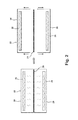
- FIG. 1 is a schematic view of a heating oven and a thermoforming box, which are used for laminating a laminate to a large part.
- FIG. 2 schematically illustrates a pre-heating treatment where the laminate is pre-heated in the oven.
- FIG. 3 schematically illustrates a pre-heating treatment step for the large part, in the form of a metallic part, in the thermoforming box.
- FIG. 4 schematically illustrates a transfer of the pre-heated laminate in the heating oven to the thermoforming box, which already contains the part.
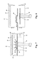
- FIG. 5 schematically illustrates a vacuum phase where a low pressure, such as a vacuum, is applied on both sides of the laminate in the thermoforming box.
- FIG. 6 schematically illustrates an upwardly movement of the part to the laminate, while the vacuum is exhausted above the laminate and a vacuum is maintained in the lower portion.
- FIG. 7 schematically illustrates the bonding of the laminate on the part, with air pressure applied downwardly to the laminate.
- FIG. 8 schematically illustrates cooling and unloading of a laminated part after the heating elements are turned off and the vacuum on the lower half and pressure in the upper half are exhausted.
- Embodiments of the invention are generally directed toward the method of thermoforming a laminate to a part. Including thermoforming the laminate to a metallic part used in home appliances such that the laminate provides the metallic part with a final finish which meets at least one of an aesthetic and functional purpose.
- Embodiments of the invention address the problem of thermoforming the laminate to the exterior of a large part without adversely impacting the quality of the laminate such as tearing, creasing, or delamination.
- FIG. 1 schematically illustrates a heating oven 22 and a thermoforming box 30 used for laminating a laminate to a large part.
- the heating oven 22 may include a separating upper half 24 and a lower half 26 to open and close the heating oven 22.
- the heating oven 22 may also include one or more heating elements 28 coupled to the upper half 24 and the lower half 26, respectively.
- the thermoforming box 30 may also include a separating upper half 32 and lower half 34.
- a heating element 36 may be coupled to the upper half 32 to provide a predetermined amount of heat energy.
- a buck 40 may be operably coupled to the lower half 34 and may be configured to move upwardly or downwardly relative to the lower half 34.
- the buck 40 may include high molecular weight plastic or thermally conductive materials and may include a plurality of vacuum openings (not shown) through which a vacuum may be drawn against an object lying on the buck 40. Further, the buck 40 may be coated with a non-stick coating, such as Teflon, to aid in removal of the large part 31.
- the buck 40 may also include an external heating source such as a heating element 38 or temperature controller to apply heat energy to the part (not shown) coupled to the buck 40.
- the thermoforming box 30 may include at least two conduits 44, 46, each of which may be coupled to the upper half 32 and the lower half 34, respectively.
- the two conduits 44, 46 may be further operably coupled to pressure systems for increasing or decreasing the pressure within the interior of the thermoforming box 30.
- pressure systems may include a vacuum pump to create the negative pressure.
- FIGS. 2 through 8 illustrate portions of a thermoforming process for applying a laminate to a large part according to one embodiment of the invention. It may be understood that the sequence of steps depicted in FIGS. 2 through 8 is for illustrative purposes only and is not meant to limit the method in any way as it is understood that the steps may proceed in a different logical order, additional or intervening steps may be included, or the described steps may be divided into multiple steps, without detracting from the embodiments of the invention.
- FIG. 2 schematically illustrates a pre-heating treatment for a laminate 20 before thermoforming of the laminate 20.
- the laminate 20 may be initially cut to a predetermined size from the laminate roll before the laminate 20 is moved to a clamp frame or other suitable means coupled to any transfer system (not shown) to the heating oven 22.
- the laminate 20 may include multilayered films including at least one of a protection layer, a decoration layer, an adhesive layer, and a release film. Exemplary multilayered laminates are disclosed in U. S. Patent No. 7,854,985 , U. S. Patent No. 6,565,955 , and U. S. Patent 6,858,287 .
- the protection layer may include Poly(methyl methacrylate) (PMMA) or any other suitable polymer material.
- the decoration layer may include a metallic layer or polymer layer such as polyvinylidene fluoride (PVDF), polyvinyl chloride (PVC), acrylonitrile butadiene styrene (ABS), or others as necessary.
- the adhesive layer may include an adhesive which is configured to adhere to an adjacent material based on at least one of the temperatures and pressures on the adhesive layer.
- the release film may be delaminated before the adhesive layer is heat treated in the heating oven 22.
- the two halves 24, 26 of the oven 22 may be separated such that the laminate 20 may be placed within the heating oven 22.
- the heating oven 22 may then be closed and the heaters 28 may be energized to heat the laminate 20 to a predetermined temperature for a predetermined time period.
- the laminate 20 may be heated up to approximately 160°C (320°F) (i.e. the appropriate processing temperature for that class of material) for approximately 1.5 to 3 minutes.
- Other heating conditions may be used for other laminates having a different stack layer.
- a laminate 20 having a polymer decoration layer may require lower heat energy than the laminate having the metallic decoration layer therein.
- the pre-heating temperature is typically a function of the thermoforming temperature of the particular laminate 20 being used, which is either provided by the manufacturer or may be experimentally determined.
- the laminate 20 may be heated by the heaters 28 from either or both the top and bottom sides of the laminate 20.
- the heating oven 22 may open in anticipation of transferring the laminate 20 to the thermoforming box 30 for thermoforming. It is also contemplated that the laminate 20 may remain in the oven 22 and may be maintained at the pre-heat temperature, or any other suitable temperature, until the thermoforming box 30 is ready to receive the laminate 20.
- the large part 31 may also be preheated. This may be done concurrently or sequentially with the preheating of the laminate 20.
- the large part 31 may be preheated in the thermoforming box 30, which for shorter overall cycle time may done while the laminate 20 is preheated in the heating oven 22.
- the large part 31 may be a metallic part such as a dishwasher, laundry treating appliance, automotive panel, or refrigerator.
- the part 31 may include a cast, formed, drawn, or stamped metallic component of a home appliance.
- the part 31 may also include any plastic component of a home appliance or an automobile or other similar industrial applications.
- the large part 31 may be loaded on the buck 40 positioned in the lower half 34.
- the large part 31 may be heated to a predetermined temperature by the heating element 38 or other heating source operably coupled to the buck 40 to provide the large part 31 with a predetermined amount of heat energy.
- the heating element 38 may be configured to heat the large part 31 at approximately 76-94°C (170-200°F).
- the large part 31 may then be continuously heated at that temperature by the buck 40 through the end of the thermoforming process.
- the large part 31 may also be provided with additional heat energy from the heating element 36 located in the upper half 32 or another external heating source.
- the heating element 36 When the heating element 36 is turned ON, the large part 31 may move upwardly toward the heating element 36 to improve the radiant heat transfer from the heating element 36 to the large part 31.
- the heating element 36 coupled to the upper half 32 After the passage of a predetermined time period, the heating element 36 coupled to the upper half 32 may be turned OFF while the heating element coupled to the buck 40 may remain ON until the end of the thermoforming process.
- the large part 31, coupled to the buck 40 may then be moved back downwardly to its original position and the thermoforming box 30 may open to receive the laminate 20, which was heated in the heating oven 22 in FIG. 2 .
- FIG. 4 schematically illustrates a transfer of the pre-heated laminate 20 from the heating oven 22 to the thermoforming box 30 in which the large part 31 is already positioned to laminate the laminate 20 to the large part 31.
- thermoforming box 30 When the laminate 20 is transferred to the thermoforming box 30, a portion of the pre-heated laminate 20 may sag downwardly due to the relative size of the laminate 20, which is needed to cover the large part 31.
- the thermoforming box 30 may then be closed to form a seal along the edge of the laminate 20, which may separate the thermoforming box 30 into two portions, an upper portion 50 and a lower portion 52.
- the upper portion 50 may be a space formed by the upper half 32 and the laminate 20, while the lower portion 52 may be a space formed by the lower half 34 and the laminate 20.
- FIG. 5 schematically illustrates a vacuum phase where a low pressure, such as a vacuum, is applied on both sides of the laminate 20 in the thermoforming box 30.
- a low pressure such as a vacuum
- vacuum it is meant any air pressure lower than the atmospheric pressure of approximately 101353 N/m 2 (14.7 psi).
- the vacuum may be separately applied to the both upper portion 50 and lower portion 52 of the thermoforming box 30 through the conduits 44, 46 coupled to one or more vacuum pumps and valves (not shown).
- the degree of vacuum for above and below the laminate 20 may be equal or configured to be different. As illustrated, a higher vacuum having a lower air pressure may be applied to the lower portion 52 and a lower vacuum having a higher air pressure may be applied to the upper portion 50 for the large part 31.
- the lower portion 50 of the thermoforming box 30 may be provided with the degree of vacuum of approximately 0.5 psi and the upper portion 50 may be provided with the degree of vacuum slightly greater than 3447 N/m 2 (0.5 psi).
- sagging of the pre-heated laminate 20 may occur in the vertical direction to form a partially concave surface.
- laminate 20 having an area of 112 x 91 cm (44 ⁇ 36 inches) with an effective area of 10220 cm 2 (1584 inch 2) , approximately 7,62 cm (3 inches) of sagging in the center of the laminate 20 in the vertical direction may occur.
- the sagging is sufficient to provide a pre-stretching of the laminate 20 while preventing the laminate from coming into initial contact with the large part 31.
- the degree of sagging is also determined by the required presentation of the laminate 20 to the large part 31 during forming.
- the pressures applied cause the laminate to deflect toward the large part 31 to effect the pre-stretching
- the differential vacuum may be controlled to prevent too much sagging of the laminate 20 and keep it relatively planar.
- the heating element 38 or by another external heating source may still be continuously turned ON to maintain the large part 31 at approximately 76-94°C (170-200°F).
- FIG. 6 schematically illustrates an upward movement of the large part 31 to the laminate 20, while the vacuum is exhausted above the laminate 20 and a vacuum is maintained in the lower portion 52 of the thermoforming box 30.
- the large part 31 coupled to the buck 40 may be configured to move upwardly by a predetermined length to initiate physical contact with the laminate 20 while maintaining the degree of vacuum in the both upper and lower portion 50, 52 of the thermoforming box 30.
- the vacuum in the upper portion 50 may be exhausted to increase the pressure in the upper portion 50 from the vacuum to the atmospheric pressure, while maintaining the degree of vacuum in the lower portion 52 of the thermoforming box 30.
- the laminate 20 may also be provided with a pressure which corresponds to a pressure difference between the atmospheric pressure and the vacuum applied on the upper portion 50 across the surface of the laminate 20.
- the pressure difference may work as a driving force to push the laminate 20 toward the large part 31.
- the laminate 20 may then fully conform to the surface of the large part 31 for full coverage. Maintaining the vacuum in the lower portion 52 may be effective in further pulling the laminate 20 toward the large part 31.
- a sagging portion of the laminate 20 may work advantageously in further fully conforming the laminate 20 to the surface of the large part 31.
- vacuum openings (not shown) operably coupled to the buck 40, such as through the buck 40, may work advantageously in consuming any trapped air between the laminate 20 and the large part 31. It may be understood that while the upward movement of the buck 40 and exhaustion of vacuum may occur in a sequential order, they may alternatively occur practically at the same time.
- the large part 31 may include openings (not shown), such as through the large part 31, which may allow for the escape of any trapped air between the laminate 20 and the large part 31 during application of the laminate 20.
- the openings may be intentionally included in portions of the large part 31, such as large surfaces of the large part 31, to allow air to be evacuated from such locations to aid in reducing the bubbling or rippling of the laminate 20.
- air may be removed through the openings in the large part such that the laminate 20 may fully conform to the surface of the large part 31, this may include that a portion of the laminate 20 may be drawn into the openings in the large part 31.
- the laminate 20 may be provided with the additional air pressure and heat energy to bond the laminate 20 on the surface of the large part 31, as illustrated in FIG. 7 .
- the adhesive layer in the laminate 20 may have an adhesive composition that is both temperature and pressure sensitive and adhesion may be effectuated by concurrently applying a predetermined pressure and temperature.
- An air pressure of as much as 206844 N/m 2 (30 psi) may be applied to the laminate 20 in the upper portion 50 of the thermoforming box 30 through the conduit 44.
- the heating element 36 may be heated as high as 171°C (340°F), or a suitable temperature for that given material, to provide heat energy to fully bond the laminate 20 to the large part 31.
- the residual processing heat may be sufficient and the heating element 36 may be turned OFF.
- the temperature for heating element 36 may be determined based on multiple parameters including an activation temperature of the adhesive in the laminate 20 or the maximum processing temperature limit of the laminate 20.
- the temperature of the heating element 36 may be set to be greater than 121°C (250°F) to effect the activation of the adhesive in the laminate 20.
- the temperature may not go up above 171°C (340°F), at which the laminate 20 may begin to crack.
- the laminate may include an adhesive layer which may be sensitive to only one of temperature or pressure. In that case, the steps described in FIG. 7 may need to be adjusted accordingly. For example, if the adhesive layer is only temperature dependent, additional air pressure need not be applied.
- the laminate 20 may bond to the surface of the large part 31 to form a laminated part 54. Then the heating elements 36, 38 may be turned OFF to cool down the laminated part 54. The pressure in the upper portion 50 and the vacuum in the lower portion 52 may also be exhausted to return the pressure in both the upper and lower portions 50, 52 to atmospheric pressure. After a predetermined time, the thermoforming box 30 may be opened to unload the laminated part 54 out of the thermoforming box 30, as illustrated in FIG. 8 .
- Another embodiment of the invention may include a method of applying a laminate having an adhesive layer to a contoured surface of an article.
- the article may be a metal article or a non-metal article such as a plastic article.
- the article is a metal article, such as the front of an appliance, illustrative examples include a dishwasher, a refrigerator, and a clothes washer or dryer.
- Such a method may include heating the laminate to a first temperature corresponding to a thermoformable temperature for the laminate. As with the above described embodiment this may include heating both sides of the laminate or may include heating a single side of the laminate.
- the laminate may be pre-heated exteriorly of the thermoforming box or within the thermoforming box.
- the laminate with the adhesive layer may be heated until the laminate reaches a predetermined draw ratio such as a predetermined draw ratio or is heated until a specific sag point is reached.
- a predetermined draw ratio such as a predetermined draw ratio or is heated until a specific sag point is reached.
- the temperature at which a predetermined draw ratio or degree of sagging is reached will be laminate-dependent.
- the adhesive may be a thermal adhesive, such as a hot melt adhesive, that will bond at a predetermined temperature. Typically, such adhesives are solid until heated to the predetermined bonding temperature, where the adhesive is suitable for bonding.
- the bonding temperature is typically adhesive-dependent.
- thermoformable temperature of the laminate is laminate-dependent because of the different characteristics of the laminate and the adhesive and is not limiting to the invention. However, for the metalized laminates described above, the temperature for the desired is near 76-154°C (170°F - 310°F).
- the article may be heated to a temperature above a bonding temperature such as an instantaneous bonding temperature of the adhesive forming the adhesive layer, but below the thermoformable temperature of the laminate. This may include that the article is heated in the range of temperatures near 76-94°C (170°F - 200°F). Heating the article may include placing the article on the buck where it may be heated in the thermoforming box. The article may be heated by heaters affixed to the thermoforming box as well as a recirculation heating element within the buck. This may include heating the buck to a temperature above an instantaneous bonding temperature for the adhesive but below the thermoformable temperature. Heating the article may also include pre-heating the article exteriorly of the thermoforming box. The article may then be maintained at the bonding temperature within the thermoforming box such as by the heated buck.
- a bonding temperature such as an instantaneous bonding temperature of the adhesive forming the adhesive layer, but below the thermoformable temperature of the laminate. This may include that the article is heated in the range
- the laminate is stretched and/or pulled over the surface of the article. If the article is not warm enough, the thermal adhesive will cool below the bonding temperature, effecting a bonding of at least parts of the laminate, before the laminate has been completely stretched and/or pulled over the surface of the article, which will lead to a rippling of the laminate that presents an unappealing appearance. Heating the steel before the laminate is applied may allow for proper adhesion.
- the heated laminate may be positioned above the heated article such as in the thermoforming box.
- the thermoforming box may then be closed to form a seal along the edge of the laminate.
- the laminate may fluidly separate the interior into a first portion, on one side of the laminate, and a second portion, on an opposite side of the laminate. Once sealed, the pressure in the first portion and the second portion may be changed to control the stretching of the pre-heated laminate.
- a portion of the pre-heated laminate may sag downwardly due to the relative size of the laminate, which is needed to cover the article.
- a differential pressure may be applied to the laminate such that the greater pressure is in the lower portion.
- the differential pressure is applied by applying a low pressure, less than atmospheric, on each side of the laminate, with the low pressure below the laminate being greater than the low pressure above the laminate.
- Other methods to apply the differential pressure include increasing the pressure in the lower portion, with or without a decreasing of the pressure in the upper portion.
- the differential pressure may be applied such that the pressure above the laminate is increased relative to the pressure below the laminate. Given the effect of gravity, it is possible to increase stretching even when the pressure above the laminate is, in an absolute sense, less than the pressure below the laminate.
- the heated laminate may then be rapidly applied onto the contoured surface of the article by applying a differential pressure across the laminate to conform or draw the laminate across the contoured surface of the article without ripples in the laminate. This may be done while the laminate is at the thermoformable temperature and the article is at the bonding temperature.
- the stretched shape, convex, of the laminate may be controlled by maintaining a differential pressure across the laminate.
- the applying of the differential pressure is accomplished by applying a low pressure, less than atmospheric pressure, on both sides of the laminated, with the low pressure on a first side, the same side of the laminate as the article, being lower than the low pressure on the second side, opposite the first side, of the laminate to obtain the desired amount of sagging to pre-stretch the laminate.
- Applying the low pressure may be accomplished by evacuating fluid, such as air, from below and above the laminate when the box is initially exposed to atmospheric pressure during insertion of the article and/or laminate.
- the evacuation of the air may be accomplished by evacuating from the box, such as with a conduit coupled to a pump, or through the buck.
- the lower pressure on the lower side draws the laminate towards the article.
- a high pressure greater than the low pressure, may be applied to the second portion of the box on the second side of the laminate, while the pressure in the first portion on the first side of the laminate is held at a lower pressure or evacuated below atmospheric pressure.
- the high pressure may include a pressure of at least 1 atmosphere.
- applying the high pressure may include fluidly coupling the second side to atmosphere and bringing the upper portion to atmosphere and then fluidly sealing it to the atmosphere and pressurizing it to greater than one atmosphere.
- applying the differential pressure may include evacuating air from below the laminate and pressurizing air above the laminate.
- Air pressure applied from the top side of the laminate aids in the stretching of the laminate in order to reach the desired shape/form of the article in accordance with the draw ratio for the part and laminate.
- the pressurized air forces the laminate into the convex shape towards the part below.
- the degree of convexness of the laminate can be controlled by the air to provide the desired draw ratio for the combination of the laminate and part.
- Rapidly applying the laminate may include instantaneously applying the laminate. Such instantaneously applying the laminate may include applying the laminate within 3 seconds and more preferably within 0.5 seconds. Rapidly applying the laminate may also include applying the laminate before any portion of the adhesive falls below the bonding temperature. Air being evacuated through the buck may also aide to uniformly apply the laminate while achieving vacuum to ensure there are no air bubbles trapped. While the rapid application of the laminate has been described with respect to an exemplary process, it will be understood that applying the differential pressure may be accomplished in any combination of high and low pressures: low and lower, high and higher, and high and low.
- the draw ratio is a measure of the overall extension of the laminate as it is stretched against the part surface.
- the draw ratio is laminate-dependent.
- Non-metalized laminates may have a draw ratio equal to or greater than 1:1.
- a metalized laminate, which has a metallic layer, may have a smaller draw ratio than its non-metalized counterpart. Such a metalized laminate may also take longer to heat to desired temperature that coincides with desired sag point of laminate.
- the article After applying the differential pressure the article may be cooled. When the laminate is cooled it may be fully adhered to the article.
- Such cooling may include cooling the buck such as by passing fluid through the buck.
- the buck may act as a heat sink to aid with the cooling. Further, depending on the buck material chosen, the buck may work as a thermal conductor during heating and then as a thermal sink during the cooling process.
- thermoforming process in the above describe embodiments of the invention have specific applicability to large parts (appliance panels, car doors, etc.), which have special requirements over small parts (cell phones, computer cases, etc.) because of the extra difficulties encountered with large parts and applying laminate without wrinkles, creases or tearing, especially given that the larger laminate tends to sag more, in absolute terms, than a smaller laminate. While the process does have special applicability to large parts, it can also be used with small parts, which is in contrast to current small part techniques that cannot be used on large parts.
- Embodiments of the invention described herein use a method of laminating the laminate to a large part by controlling the temperature and pressure on the laminate and the large part to form a laminated part with enhanced aesthetic and/or functional characteristics.
- a laminated part, without having any tearing, creasing or delamination, is prepared. It is noted that the invention may be used for both metallic and non-metallic parts.
Landscapes
- Engineering & Computer Science (AREA)
- Mechanical Engineering (AREA)
- Blow-Moulding Or Thermoforming Of Plastics Or The Like (AREA)
Abstract
Description
- A formed part, such as the top cover or front panel of home appliances or a center console of automotive vehicles, may require a final finish on the exterior of the formed part to provide an aesthetic touch or functional purpose. The formed parts may include a metallic part such as a steel part, or a non-metallic part. The formed part may be formed by molding, stamping, or thermoforming.
- For large parts such as car doors, refrigerator doors, and dishwasher doors, for example, thermoforming a laminate to the part has resulted in unwanted tearing, or rippling of the laminate as it is stretched over the part, resulting in an unacceptable product. While such tearing and rippling occurs relatively infrequently for smaller parts, such as laptop cases, the thermoforming techniques used for smaller parts have not provided satisfactory results for larger parts.
- An embodiment of the invention includes a method of applying a laminate having an adhesive layer to a contoured surface of an article.
- In the drawings:
-
FIG. 1 is a schematic view of a heating oven and a thermoforming box, which are used for laminating a laminate to a large part. -
FIG. 2 schematically illustrates a pre-heating treatment where the laminate is pre-heated in the oven. -
FIG. 3 schematically illustrates a pre-heating treatment step for the large part, in the form of a metallic part, in the thermoforming box. -
FIG. 4 schematically illustrates a transfer of the pre-heated laminate in the heating oven to the thermoforming box, which already contains the part. -
FIG. 5 schematically illustrates a vacuum phase where a low pressure, such as a vacuum, is applied on both sides of the laminate in the thermoforming box. -
FIG. 6 schematically illustrates an upwardly movement of the part to the laminate, while the vacuum is exhausted above the laminate and a vacuum is maintained in the lower portion. -
FIG. 7 schematically illustrates the bonding of the laminate on the part, with air pressure applied downwardly to the laminate. -
FIG. 8 schematically illustrates cooling and unloading of a laminated part after the heating elements are turned off and the vacuum on the lower half and pressure in the upper half are exhausted. - Embodiments of the invention are generally directed toward the method of thermoforming a laminate to a part. Including thermoforming the laminate to a metallic part used in home appliances such that the laminate provides the metallic part with a final finish which meets at least one of an aesthetic and functional purpose.
- Embodiments of the invention address the problem of thermoforming the laminate to the exterior of a large part without adversely impacting the quality of the laminate such as tearing, creasing, or delamination.
-
FIG. 1 schematically illustrates aheating oven 22 and athermoforming box 30 used for laminating a laminate to a large part. As illustrated, theheating oven 22 may include a separatingupper half 24 and alower half 26 to open and close theheating oven 22. Theheating oven 22 may also include one ormore heating elements 28 coupled to theupper half 24 and thelower half 26, respectively. - The
thermoforming box 30 may also include a separatingupper half 32 andlower half 34. Aheating element 36 may be coupled to theupper half 32 to provide a predetermined amount of heat energy. Abuck 40 may be operably coupled to thelower half 34 and may be configured to move upwardly or downwardly relative to thelower half 34. Thebuck 40 may include high molecular weight plastic or thermally conductive materials and may include a plurality of vacuum openings (not shown) through which a vacuum may be drawn against an object lying on thebuck 40. Further, thebuck 40 may be coated with a non-stick coating, such as Teflon, to aid in removal of thelarge part 31. Thebuck 40 may also include an external heating source such as aheating element 38 or temperature controller to apply heat energy to the part (not shown) coupled to thebuck 40. - The
thermoforming box 30 may include at least twoconduits upper half 32 and thelower half 34, respectively. The twoconduits thermoforming box 30. Such pressure systems may include a vacuum pump to create the negative pressure. -
FIGS. 2 through 8 illustrate portions of a thermoforming process for applying a laminate to a large part according to one embodiment of the invention. It may be understood that the sequence of steps depicted inFIGS. 2 through 8 is for illustrative purposes only and is not meant to limit the method in any way as it is understood that the steps may proceed in a different logical order, additional or intervening steps may be included, or the described steps may be divided into multiple steps, without detracting from the embodiments of the invention. -
FIG. 2 schematically illustrates a pre-heating treatment for alaminate 20 before thermoforming of thelaminate 20. Thelaminate 20 may be initially cut to a predetermined size from the laminate roll before thelaminate 20 is moved to a clamp frame or other suitable means coupled to any transfer system (not shown) to theheating oven 22. - The
laminate 20 may include multilayered films including at least one of a protection layer, a decoration layer, an adhesive layer, and a release film. Exemplary multilayered laminates are disclosed inU. S. Patent No. 7,854,985 ,U. S. Patent No. 6,565,955 , andU. S. Patent 6,858,287 . The protection layer may include Poly(methyl methacrylate) (PMMA) or any other suitable polymer material. The decoration layer may include a metallic layer or polymer layer such as polyvinylidene fluoride (PVDF), polyvinyl chloride (PVC), acrylonitrile butadiene styrene (ABS), or others as necessary. The adhesive layer may include an adhesive which is configured to adhere to an adjacent material based on at least one of the temperatures and pressures on the adhesive layer. The release film may be delaminated before the adhesive layer is heat treated in theheating oven 22. - The two
halves oven 22 may be separated such that thelaminate 20 may be placed within theheating oven 22. Theheating oven 22 may then be closed and theheaters 28 may be energized to heat thelaminate 20 to a predetermined temperature for a predetermined time period. In the case of thelaminate 20, which may have a metallic decoration layer, thelaminate 20 may be heated up to approximately 160°C (320°F) (i.e. the appropriate processing temperature for that class of material) for approximately 1.5 to 3 minutes. Other heating conditions may be used for other laminates having a different stack layer. For example, alaminate 20 having a polymer decoration layer may require lower heat energy than the laminate having the metallic decoration layer therein. The pre-heating temperature is typically a function of the thermoforming temperature of theparticular laminate 20 being used, which is either provided by the manufacturer or may be experimentally determined. - The
laminate 20 may be heated by theheaters 28 from either or both the top and bottom sides of thelaminate 20. - Once the pre-heating of the
laminate 20 is completed, theheating oven 22 may open in anticipation of transferring thelaminate 20 to thethermoforming box 30 for thermoforming. It is also contemplated that thelaminate 20 may remain in theoven 22 and may be maintained at the pre-heat temperature, or any other suitable temperature, until thethermoforming box 30 is ready to receive thelaminate 20. - As shown in
FIG. 3 , thelarge part 31 may also be preheated. This may be done concurrently or sequentially with the preheating of thelaminate 20. Thelarge part 31 may be preheated in thethermoforming box 30, which for shorter overall cycle time may done while thelaminate 20 is preheated in theheating oven 22. - The
large part 31 may be a metallic part such as a dishwasher, laundry treating appliance, automotive panel, or refrigerator. Typically thepart 31 may include a cast, formed, drawn, or stamped metallic component of a home appliance. Thepart 31 may also include any plastic component of a home appliance or an automobile or other similar industrial applications. - As illustrated, the
large part 31 may be loaded on thebuck 40 positioned in thelower half 34. Thelarge part 31 may be heated to a predetermined temperature by theheating element 38 or other heating source operably coupled to thebuck 40 to provide thelarge part 31 with a predetermined amount of heat energy. For example, theheating element 38 may be configured to heat thelarge part 31 at approximately 76-94°C (170-200°F). Thelarge part 31 may then be continuously heated at that temperature by thebuck 40 through the end of the thermoforming process. - The
large part 31 may also be provided with additional heat energy from theheating element 36 located in theupper half 32 or another external heating source. When theheating element 36 is turned ON, thelarge part 31 may move upwardly toward theheating element 36 to improve the radiant heat transfer from theheating element 36 to thelarge part 31. After the passage of a predetermined time period, theheating element 36 coupled to theupper half 32 may be turned OFF while the heating element coupled to thebuck 40 may remain ON until the end of the thermoforming process. Thelarge part 31, coupled to thebuck 40, may then be moved back downwardly to its original position and thethermoforming box 30 may open to receive the laminate 20, which was heated in theheating oven 22 inFIG. 2 . -
FIG. 4 schematically illustrates a transfer of thepre-heated laminate 20 from theheating oven 22 to thethermoforming box 30 in which thelarge part 31 is already positioned to laminate the laminate 20 to thelarge part 31. - When the laminate 20 is transferred to the
thermoforming box 30, a portion of thepre-heated laminate 20 may sag downwardly due to the relative size of the laminate 20, which is needed to cover thelarge part 31. Thethermoforming box 30 may then be closed to form a seal along the edge of the laminate 20, which may separate thethermoforming box 30 into two portions, anupper portion 50 and alower portion 52. Theupper portion 50 may be a space formed by theupper half 32 and the laminate 20, while thelower portion 52 may be a space formed by thelower half 34 and the laminate 20. -
FIG. 5 schematically illustrates a vacuum phase where a low pressure, such as a vacuum, is applied on both sides of the laminate 20 in thethermoforming box 30. By vacuum, it is meant any air pressure lower than the atmospheric pressure of approximately 101353 N/m2 (14.7 psi). The vacuum may be separately applied to the bothupper portion 50 andlower portion 52 of thethermoforming box 30 through theconduits - It may be understood that, while applying the vacuum to the
thermoforming box 30, the degree of vacuum for above and below the laminate 20 may be equal or configured to be different. As illustrated, a higher vacuum having a lower air pressure may be applied to thelower portion 52 and a lower vacuum having a higher air pressure may be applied to theupper portion 50 for thelarge part 31. For example, thelower portion 50 of thethermoforming box 30 may be provided with the degree of vacuum of approximately 0.5 psi and theupper portion 50 may be provided with the degree of vacuum slightly greater than 3447 N/m2 (0.5 psi). - Under this condition, partly due to the pressure difference applied across the entire surface of the
pre-heated laminate 20, sagging of thepre-heated laminate 20 may occur in the vertical direction to form a partially concave surface. For example, it was found that forlaminate 20 having an area of 112 x 91 cm (44×36 inches) with an effective area of 10220 cm2 (1584 inch2), approximately 7,62 cm (3 inches) of sagging in the center of the laminate 20 in the vertical direction may occur. - The sagging is sufficient to provide a pre-stretching of the laminate 20 while preventing the laminate from coming into initial contact with the
large part 31. The degree of sagging is also determined by the required presentation of the laminate 20 to thelarge part 31 during forming. - While the pressures applied cause the laminate to deflect toward the
large part 31 to effect the pre-stretching, it is possible to effect the pre-stretching by altering the pressure differential to create a convex surface that bows away from thelarge part 31. When the upper andlower portions thermoforming box 30, gravity will naturally cause some sagging. It is contemplated that the differential vacuum may be controlled to prevent too much sagging of the laminate 20 and keep it relatively planar. - While the vacuum is applied on the laminate 20, the
heating element 38 or by another external heating source may still be continuously turned ON to maintain thelarge part 31 at approximately 76-94°C (170-200°F). -
FIG. 6 schematically illustrates an upward movement of thelarge part 31 to the laminate 20, while the vacuum is exhausted above the laminate 20 and a vacuum is maintained in thelower portion 52 of thethermoforming box 30. As illustrated, thelarge part 31 coupled to thebuck 40 may be configured to move upwardly by a predetermined length to initiate physical contact with the laminate 20 while maintaining the degree of vacuum in the both upper andlower portion thermoforming box 30. After thelarge part 31 makes contact with the laminate 20, the vacuum in theupper portion 50 may be exhausted to increase the pressure in theupper portion 50 from the vacuum to the atmospheric pressure, while maintaining the degree of vacuum in thelower portion 52 of thethermoforming box 30. - Once the vacuum exhausts in the
upper portion 50 of thethermoforming box 30 the laminate 20 may also be provided with a pressure which corresponds to a pressure difference between the atmospheric pressure and the vacuum applied on theupper portion 50 across the surface of the laminate 20. The pressure difference may work as a driving force to push the laminate 20 toward thelarge part 31. The laminate 20 may then fully conform to the surface of thelarge part 31 for full coverage. Maintaining the vacuum in thelower portion 52 may be effective in further pulling the laminate 20 toward thelarge part 31. - Under this condition, a sagging portion of the laminate 20 may work advantageously in further fully conforming the laminate 20 to the surface of the
large part 31. Additionally, vacuum openings (not shown) operably coupled to thebuck 40, such as through thebuck 40, may work advantageously in consuming any trapped air between the laminate 20 and thelarge part 31. It may be understood that while the upward movement of thebuck 40 and exhaustion of vacuum may occur in a sequential order, they may alternatively occur practically at the same time. - The
large part 31 may include openings (not shown), such as through thelarge part 31, which may allow for the escape of any trapped air between the laminate 20 and thelarge part 31 during application of the laminate 20. The openings may be intentionally included in portions of thelarge part 31, such as large surfaces of thelarge part 31, to allow air to be evacuated from such locations to aid in reducing the bubbling or rippling of the laminate 20. During application, air may be removed through the openings in the large part such that the laminate 20 may fully conform to the surface of thelarge part 31, this may include that a portion of the laminate 20 may be drawn into the openings in thelarge part 31. - After the laminate 20 fully conforms to the surface of the
large part 31, the laminate 20 may be provided with the additional air pressure and heat energy to bond the laminate 20 on the surface of thelarge part 31, as illustrated inFIG. 7 . For this, the adhesive layer in the laminate 20 may have an adhesive composition that is both temperature and pressure sensitive and adhesion may be effectuated by concurrently applying a predetermined pressure and temperature. - An air pressure of as much as 206844 N/m2 (30 psi) may be applied to the laminate 20 in the
upper portion 50 of thethermoforming box 30 through theconduit 44. At the same time, theheating element 36 may be heated as high as 171°C (340°F), or a suitable temperature for that given material, to provide heat energy to fully bond the laminate 20 to thelarge part 31. Alternatively, the residual processing heat may be sufficient and theheating element 36 may be turned OFF. - The temperature for
heating element 36 may be determined based on multiple parameters including an activation temperature of the adhesive in the laminate 20 or the maximum processing temperature limit of the laminate 20. For example, the temperature of theheating element 36 may be set to be greater than 121°C (250°F) to effect the activation of the adhesive in thelaminate 20. In contrast, the temperature may not go up above 171°C (340°F), at which the laminate 20 may begin to crack. - It is noted that, in another example, the laminate may include an adhesive layer which may be sensitive to only one of temperature or pressure. In that case, the steps described in
FIG. 7 may need to be adjusted accordingly. For example, if the adhesive layer is only temperature dependent, additional air pressure need not be applied. - After the passage of a predetermined time period under a predetermined temperature and additional air pressure, the laminate 20 may bond to the surface of the
large part 31 to form alaminated part 54. Then theheating elements laminated part 54. The pressure in theupper portion 50 and the vacuum in thelower portion 52 may also be exhausted to return the pressure in both the upper andlower portions thermoforming box 30 may be opened to unload thelaminated part 54 out of thethermoforming box 30, as illustrated inFIG. 8 . - Another embodiment of the invention may include a method of applying a laminate having an adhesive layer to a contoured surface of an article. By way of example, the article may be a metal article or a non-metal article such as a plastic article. In the exemplary process, the article is a metal article, such as the front of an appliance, illustrative examples include a dishwasher, a refrigerator, and a clothes washer or dryer. Such a method may include heating the laminate to a first temperature corresponding to a thermoformable temperature for the laminate. As with the above described embodiment this may include heating both sides of the laminate or may include heating a single side of the laminate. The laminate may be pre-heated exteriorly of the thermoforming box or within the thermoforming box.
- The laminate with the adhesive layer may be heated until the laminate reaches a predetermined draw ratio such as a predetermined draw ratio or is heated until a specific sag point is reached. The temperature at which a predetermined draw ratio or degree of sagging is reached will be laminate-dependent.
- The adhesive may be a thermal adhesive, such as a hot melt adhesive, that will bond at a predetermined temperature. Typically, such adhesives are solid until heated to the predetermined bonding temperature, where the adhesive is suitable for bonding. The bonding temperature is typically adhesive-dependent.
- The thermoformable temperature of the laminate is laminate-dependent because of the different characteristics of the laminate and the adhesive and is not limiting to the invention. However, for the metalized laminates described above, the temperature for the desired is near 76-154°C (170°F - 310°F).
- The article may be heated to a temperature above a bonding temperature such as an instantaneous bonding temperature of the adhesive forming the adhesive layer, but below the thermoformable temperature of the laminate. This may include that the article is heated in the range of temperatures near 76-94°C (170°F - 200°F). Heating the article may include placing the article on the buck where it may be heated in the thermoforming box. The article may be heated by heaters affixed to the thermoforming box as well as a recirculation heating element within the buck. This may include heating the buck to a temperature above an instantaneous bonding temperature for the adhesive but below the thermoformable temperature. Heating the article may also include pre-heating the article exteriorly of the thermoforming box. The article may then be maintained at the bonding temperature within the thermoforming box such as by the heated buck.
- During the application of the laminate, the laminate is stretched and/or pulled over the surface of the article. If the article is not warm enough, the thermal adhesive will cool below the bonding temperature, effecting a bonding of at least parts of the laminate, before the laminate has been completely stretched and/or pulled over the surface of the article, which will lead to a rippling of the laminate that presents an unappealing appearance. Heating the steel before the laminate is applied may allow for proper adhesion.
- As with the above described embodiment, the heated laminate may be positioned above the heated article such as in the thermoforming box. The thermoforming box may then be closed to form a seal along the edge of the laminate. Within the thermoforming box the laminate may fluidly separate the interior into a first portion, on one side of the laminate, and a second portion, on an opposite side of the laminate. Once sealed, the pressure in the first portion and the second portion may be changed to control the stretching of the pre-heated laminate. When the laminate is transferred to the thermoforming box, a portion of the pre-heated laminate may sag downwardly due to the relative size of the laminate, which is needed to cover the article.
- To limit this stretching, by way of example only, a differential pressure may be applied to the laminate such that the greater pressure is in the lower portion. In the exemplary embodiment, the differential pressure is applied by applying a low pressure, less than atmospheric, on each side of the laminate, with the low pressure below the laminate being greater than the low pressure above the laminate. Other methods to apply the differential pressure include increasing the pressure in the lower portion, with or without a decreasing of the pressure in the upper portion.
- To increase the stretching, the differential pressure may be applied such that the pressure above the laminate is increased relative to the pressure below the laminate. Given the effect of gravity, it is possible to increase stretching even when the pressure above the laminate is, in an absolute sense, less than the pressure below the laminate.
- The heated laminate may then be rapidly applied onto the contoured surface of the article by applying a differential pressure across the laminate to conform or draw the laminate across the contoured surface of the article without ripples in the laminate. This may be done while the laminate is at the thermoformable temperature and the article is at the bonding temperature. The stretched shape, convex, of the laminate may be controlled by maintaining a differential pressure across the laminate.
- In the exemplary process, the applying of the differential pressure is accomplished by applying a low pressure, less than atmospheric pressure, on both sides of the laminated, with the low pressure on a first side, the same side of the laminate as the article, being lower than the low pressure on the second side, opposite the first side, of the laminate to obtain the desired amount of sagging to pre-stretch the laminate. Applying the low pressure may be accomplished by evacuating fluid, such as air, from below and above the laminate when the box is initially exposed to atmospheric pressure during insertion of the article and/or laminate. The evacuation of the air may be accomplished by evacuating from the box, such as with a conduit coupled to a pump, or through the buck. The lower pressure on the lower side draws the laminate towards the article.
- During or closely after evacuation of the air, pressure may be applied from above to rapidly form and apply the laminate across all geometries of the substrate. In the exemplary process, a high pressure, greater than the low pressure, may be applied to the second portion of the box on the second side of the laminate, while the pressure in the first portion on the first side of the laminate is held at a lower pressure or evacuated below atmospheric pressure. The high pressure may include a pressure of at least 1 atmosphere. In the exemplary process, applying the high pressure may include fluidly coupling the second side to atmosphere and bringing the upper portion to atmosphere and then fluidly sealing it to the atmosphere and pressurizing it to greater than one atmosphere. In this manner, applying the differential pressure may include evacuating air from below the laminate and pressurizing air above the laminate. This sharp increase in the pressure differential rapidly applies the laminate onto the article. Air pressure applied from the top side of the laminate aids in the stretching of the laminate in order to reach the desired shape/form of the article in accordance with the draw ratio for the part and laminate. The pressurized air forces the laminate into the convex shape towards the part below. The degree of convexness of the laminate can be controlled by the air to provide the desired draw ratio for the combination of the laminate and part.
- Rapidly applying the laminate may include instantaneously applying the laminate. Such instantaneously applying the laminate may include applying the laminate within 3 seconds and more preferably within 0.5 seconds. Rapidly applying the laminate may also include applying the laminate before any portion of the adhesive falls below the bonding temperature. Air being evacuated through the buck may also aide to uniformly apply the laminate while achieving vacuum to ensure there are no air bubbles trapped. While the rapid application of the laminate has been described with respect to an exemplary process, it will be understood that applying the differential pressure may be accomplished in any combination of high and low pressures: low and lower, high and higher, and high and low.
- Further, it will be understood that all potential laminates will have different characteristics and require different process parameters and that the finish of the laminate drives the draw ratio and, correspondingly, the overall manufacturing performance. The draw ratio is a measure of the overall extension of the laminate as it is stretched against the part surface. The draw ratio is laminate-dependent. Non-metalized laminates may have a draw ratio equal to or greater than 1:1. A metalized laminate, which has a metallic layer, may have a smaller draw ratio than its non-metalized counterpart. Such a metalized laminate may also take longer to heat to desired temperature that coincides with desired sag point of laminate.
- After applying the differential pressure the article may be cooled. When the laminate is cooled it may be fully adhered to the article. Such cooling may include cooling the buck such as by passing fluid through the buck. The buck may act as a heat sink to aid with the cooling. Further, depending on the buck material chosen, the buck may work as a thermal conductor during heating and then as a thermal sink during the cooling process.
- It is noted that the thermoforming process in the above describe embodiments of the invention have specific applicability to large parts (appliance panels, car doors, etc.), which have special requirements over small parts (cell phones, computer cases, etc.) because of the extra difficulties encountered with large parts and applying laminate without wrinkles, creases or tearing, especially given that the larger laminate tends to sag more, in absolute terms, than a smaller laminate. While the process does have special applicability to large parts, it can also be used with small parts, which is in contrast to current small part techniques that cannot be used on large parts.
- Embodiments of the invention described herein use a method of laminating the laminate to a large part by controlling the temperature and pressure on the laminate and the large part to form a laminated part with enhanced aesthetic and/or functional characteristics. A laminated part, without having any tearing, creasing or delamination, is prepared. It is noted that the invention may be used for both metallic and non-metallic parts.
Claims (15)
- A method of applying a laminate (20) having an adhesive layer to a contoured surface of an article (31), the method comprising:heating the laminate (20) to a thermoformable temperature;heating the metal article (31) to a temperature above a bonding temperature of the adhesive, but below a thermoformable temperature;positioning the heated laminate (20) above the heated article (31); andrapidly applying the laminate (20) onto the contoured surface by applying a differential pressure across the laminate to conform the laminate to the contoured surface without ripples in the laminate.
- The method of claim 1 wherein the applying a differential pressure across the laminate (20) comprises evacuating fluid from below the laminate (20) and pressurizing fluid above the laminate.
- The method of claim 1 wherein the rapidly applying the laminate comprises applying the laminate within 3 seconds.
- The method of claim 1 wherein rapidly applying the laminate (20) comprises applying the laminate (20) before any portion of the adhesive falls below the bonding temperature.
- The method of claim 1 wherein heating the laminate (20) comprises heating both sides of the laminate.
- The method of claim 1 wherein heating the laminate (20) comprises heating the laminate until the laminate reaches a predetermined draw ratio which is preferably greater than 1:1.
- The method of claim 1 wherein the applying a differential pressure comprises applying a low pressure, less than atmospheric pressure, on a first side of the laminate (20), which is a same side of the laminate as the metal article (31) and applying a high pressure, greater than the low pressure, on a second side of the laminate (20) opposite the first side.
- The method of claim 7 wherein applying the high pressure comprises fluidly coupling the second side to atmosphere and then fluidly sealing the second side to atmosphere and pressurizing the second side to greater than one atmosphere.
- The method of claim 8, further comprising cooling the article after applying the differential pressure.
- The method according to any of the preceding claims wherein the article (31) is within a thermoforming box (30) and fluidly separated by the laminate (20) into a first portion (50), on one side of the laminate, and a second portion (52), on an opposite side of the laminate, and having a buck (40) supporting the article (31) in the one side.
- The method of claim 10 wherein the heating the article (31) comprises heating the buck (40) to a temperature above an instantaneous bonding temperature for the adhesive but below the thermoforming temperature.
- The method of claim 11 wherein the heating the article (31) further comprises pre-heating the article exteriorly of the thermoforming box (30).
- The method of claim 12 wherein the heating the laminate (20) further comprises pre-heating the laminate exteriorly of the thermoforming box (30).
- The method of claim 12 wherein the heating the laminate (20) comprises heating both sides of the laminate.
- The method of claim 10 wherein the heating the laminate comprises heating the laminate (20) until the laminate reaches a predetermined draw ratio which is preferably greater than 1:1.
Applications Claiming Priority (2)
| Application Number | Priority Date | Filing Date | Title |
|---|---|---|---|
| US201161551975P | 2011-10-27 | 2011-10-27 | |
| US13/465,253 US10086555B2 (en) | 2011-10-27 | 2012-05-07 | Method for forming a laminated part |
Publications (2)
| Publication Number | Publication Date |
|---|---|
| EP2586592A1 true EP2586592A1 (en) | 2013-05-01 |
| EP2586592B1 EP2586592B1 (en) | 2014-10-01 |
Family
ID=47227444
Family Applications (1)
| Application Number | Title | Priority Date | Filing Date |
|---|---|---|---|
| EP12189889.4A Not-in-force EP2586592B1 (en) | 2011-10-27 | 2012-10-25 | Method for applying a laminate onto a contoured article |
Country Status (2)
| Country | Link |
|---|---|
| US (1) | US10086555B2 (en) |
| EP (1) | EP2586592B1 (en) |
Cited By (2)
| Publication number | Priority date | Publication date | Assignee | Title |
|---|---|---|---|---|
| CN112297445A (en) * | 2019-08-01 | 2021-02-02 | B/E航空公司 | Conductive heating for HVA lamination process |
| US20220168945A1 (en) * | 2019-01-28 | 2022-06-02 | Honda Motor Co., Ltd. | Bonding apparatus and bonding method |
Families Citing this family (7)
| Publication number | Priority date | Publication date | Assignee | Title |
|---|---|---|---|---|
| ITUB20155474A1 (en) | 2015-11-11 | 2017-05-11 | Nike Innovate Cv | EQUIPMENT, AND ITS PROCEDURE, FOR THE THERMAL TREATMENT OF FOOTWEAR, IN PARTICULAR SPORTS SHOES |
| CN106407595B (en) * | 2016-10-11 | 2019-11-01 | 北京长城华冠汽车科技股份有限公司 | A kind of optimization method of the arrangements for automotive doors based on deflection contribution rate |
| TWI722417B (en) | 2018-04-25 | 2021-03-21 | 荷蘭商耐克創新有限合夥公司 | System and methods for preparing article for thermoforming |
| TWI728340B (en) | 2018-04-25 | 2021-05-21 | 荷蘭商耐克創新有限合夥公司 | System and methods for thermoforming articles |
| CN115998052B (en) * | 2018-05-18 | 2026-03-10 | 耐克创新有限合伙公司 | System and method for thermoforming an article |
| US11662708B2 (en) * | 2018-09-25 | 2023-05-30 | Scott Hinkel | Method of forming a two-dimensional image over a model |
| JP7592319B2 (en) * | 2021-12-09 | 2024-12-02 | 株式会社浅野研究所 | Thermoforming machine for molding composite materials |
Citations (8)
| Publication number | Priority date | Publication date | Assignee | Title |
|---|---|---|---|---|
| WO1999029504A1 (en) * | 1997-12-11 | 1999-06-17 | Diapek Oy | Apparatus and procedure for the coating of objects |
| WO2001032400A1 (en) * | 1999-11-02 | 2001-05-10 | Richard Warrington George | Method and apparatus for thermoforming of plastic sheets |
| US6565955B2 (en) | 1999-03-12 | 2003-05-20 | Soliant Llc | Bright indium-metallized formable film laminate |
| US6858287B2 (en) | 2001-08-10 | 2005-02-22 | Soliant Llc | Formable bright film having discontinuous metallic layers |
| WO2006105999A1 (en) * | 2005-04-04 | 2006-10-12 | Essilor International (Compagnie Generale D'optique) | Apparatus for conforming a planar film on an optical lens, method for functionalizing an optical lens by means of said apparatus, the optical lens so-obtained |
| US20070148384A1 (en) * | 2005-11-28 | 2007-06-28 | Bowden Joe A | Processes for filming biodegradable or compostable containers |
| US7854985B2 (en) | 2005-11-18 | 2010-12-21 | Soliant Llc | Decorative paint film laminate |
| EP2324991A2 (en) * | 2009-11-19 | 2011-05-25 | Navitas Co. Ltd. | Sheet bonding method, sheet bonding apparatus, laminated product and film transferred product |
Family Cites Families (45)
| Publication number | Priority date | Publication date | Assignee | Title |
|---|---|---|---|---|
| US4230764A (en) | 1979-04-30 | 1980-10-28 | The United States Of America As Represented By The Secretary Of The Army | Prestressed article |
| JPS5770610A (en) | 1980-10-20 | 1982-05-01 | Matsushita Electric Ind Co Ltd | Surface treatment of molded article |
| ES8706523A1 (en) | 1985-05-03 | 1987-07-16 | Panagiotopo Panayotis Christos | Mould, machine, and method for thermoforming. |
| GB8512243D0 (en) | 1985-05-15 | 1985-06-19 | Ici Plc | Shaped articles |
| CA1319862C (en) * | 1986-01-14 | 1993-07-06 | Bruce E. Johnson | Composite useful for paint transfer and method of use and preparation thereof |
| US4828637A (en) | 1986-07-02 | 1989-05-09 | General Motors Corporation | Method of applying painted carrier films to automobile body parts |
| US4868030A (en) * | 1986-07-02 | 1989-09-19 | General Motors Corporation | Article covered with painted carrier films |
| US4838973A (en) | 1986-07-02 | 1989-06-13 | General Motors Corporation | Method of applying painted carrier films to automobile body parts |
| US4957802A (en) | 1986-07-02 | 1990-09-18 | General Motors Corporation | Article covered with painted carrier films |
| US5707697A (en) | 1987-03-27 | 1998-01-13 | Avery Dennison Corporation | Dry paint transfer product having high DOI automotive paint coat |
| ZA884565B (en) | 1987-08-07 | 1990-02-28 | Minnesota Mining & Mfg | Method and apparatus for vacuum-application of a film to surface of an article |
| US4824506A (en) | 1988-04-21 | 1989-04-25 | General Motors Corporation | Process for protecting thermoformed films |
| JPH02215517A (en) | 1989-02-17 | 1990-08-28 | Riken Vinyl Kogyo Kk | Method and device for press lamination |
| US4981631A (en) | 1989-03-31 | 1991-01-01 | The Goodyear Tire & Rubber Company | Process for making lightweight polyester articles |
| US5030504A (en) | 1989-08-17 | 1991-07-09 | Carol Botsolas | Poly(vinyl chloride)-aluminum laminate insulation and method of production |
| US5034077A (en) | 1989-09-05 | 1991-07-23 | Jack Pata | Method for thermoforming and bonding a paint-coated polymeric film to a substrate |
| US5125994A (en) | 1989-11-01 | 1992-06-30 | Eastman Kodak Company | Thermoforming method |
| CA2148115A1 (en) | 1992-10-29 | 1994-05-11 | Walter J. Schrenk | Formable reflective multilayer body |
| JPH1058536A (en) | 1996-08-13 | 1998-03-03 | Mitsubishi Chem Corp | Thermoforming equipment for thermoplastic resin sheets |
| US6788463B2 (en) | 1998-01-13 | 2004-09-07 | 3M Innovative Properties Company | Post-formable multilayer optical films and methods of forming |
| IT1299023B1 (en) * | 1998-04-03 | 2000-02-07 | Rigo Group S R L | THERMOFORMING STATION WITH RAPID COOLING SYSTEM OF THE MOLD AND THERMOFORMING PROCESS CARRIED OUT WITH THIS |
| US6319438B1 (en) | 1998-12-15 | 2001-11-20 | Guardian Automotive Trim, Inc. | Extruded automotive trim and method of making same |
| JP4400961B2 (en) | 1999-10-15 | 2010-01-20 | サカエ理研工業株式会社 | Plastic molded product with pattern |
| WO2003041945A1 (en) * | 2001-11-12 | 2003-05-22 | Manufacturing Evolutions (Nz) Limited | Thermoplastic sheating of articles and moulding process |
| US6851943B1 (en) | 2002-01-17 | 2005-02-08 | L. L. Brown, Inc. | Continuous thermoforming machine |
| FR2842469B1 (en) | 2002-07-17 | 2004-10-15 | Plasto Sa | SELF-ADHESIVE PROTECTION SHEET FOR BODY OF MOTOR VEHICLES |
| JP2004237510A (en) | 2003-02-05 | 2004-08-26 | C I Kasei Co Ltd | Method of manufacturing vehicle window frame panel |
| US6929711B2 (en) | 2003-04-29 | 2005-08-16 | Lear Corporation | Method of making an interior trim part |
| US7837911B2 (en) | 2004-01-26 | 2010-11-23 | Sabic Innovative Plastics Ip B.V. | Methods of forming a layered article |
| US7390454B2 (en) | 2004-08-19 | 2008-06-24 | General Motors Corporation | Thermoforming process for producing class “A” finish, high gloss automotive exterior parts |
| EP1804094B1 (en) | 2004-10-08 | 2014-09-03 | Daicel Corporation | Protective film for polarizing film and polarizing multilayer body |
| JP4657909B2 (en) | 2005-12-16 | 2011-03-23 | サカエ理研工業株式会社 | Method for producing plastic molded body having grain pattern on surface |
| JP4817938B2 (en) | 2006-04-03 | 2011-11-16 | 株式会社浅野研究所 | Valve operation confirmation device for thermoforming device, thermoforming device and valve operation confirmation method thereof |
| US7708932B2 (en) | 2006-10-02 | 2010-05-04 | Ford Global Technologies, Llc | Chilled air pressure box for thermoforming a plastic sheet and a method of thermoforming the same |
| USD595965S1 (en) | 2007-01-25 | 2009-07-14 | Lg Electronics Inc. | Decorative film for home appliances |
| WO2008136970A1 (en) | 2007-05-02 | 2008-11-13 | Polyplastics Co., Ltd | Thermoformed articles from sheet incorporating cycloolefin copolymer |
| US8021135B2 (en) | 2007-06-08 | 2011-09-20 | Sabic Innovative Plastics Ip B.V. | Mold apparatus for forming polymer and method |
| JP4567717B2 (en) | 2007-09-21 | 2010-10-20 | リケンテクノス株式会社 | Decorative film and laminated decorative sheet |
| US20090099313A1 (en) | 2007-10-10 | 2009-04-16 | E. I. Du Pont De Nemours And Company | Poly(hydroxyalkanoic acid) and thermoformed articles |
| US8062451B2 (en) | 2008-02-22 | 2011-11-22 | Delta Engineered Plastics | Post molding application of an extruded film to an injection molded part |
| JP5275722B2 (en) | 2008-08-20 | 2013-08-28 | リケンテクノス株式会社 | Multilayer film |
| CN101750279B (en) | 2008-11-28 | 2012-04-04 | 上海宝钢工业检测公司 | Infrared peak area ratio determination method of PVDF resin content in fluorocarbon color-coated plate coating |
| SG172324A1 (en) | 2008-12-30 | 2011-07-28 | 3M Innovative Properties Co | Fluoropolymeric multilayer optical film and methods of making and using the same |
| JP5351597B2 (en) | 2009-04-23 | 2013-11-27 | リケンテクノス株式会社 | Vacuum forming sheet |
| DE102010029577A1 (en) | 2010-06-01 | 2011-12-01 | BSH Bosch und Siemens Hausgeräte GmbH | Facing part for a household appliance, household appliance and method for producing a facing part of a household appliance |
-
2012
- 2012-05-07 US US13/465,253 patent/US10086555B2/en active Active
- 2012-10-25 EP EP12189889.4A patent/EP2586592B1/en not_active Not-in-force
Patent Citations (8)
| Publication number | Priority date | Publication date | Assignee | Title |
|---|---|---|---|---|
| WO1999029504A1 (en) * | 1997-12-11 | 1999-06-17 | Diapek Oy | Apparatus and procedure for the coating of objects |
| US6565955B2 (en) | 1999-03-12 | 2003-05-20 | Soliant Llc | Bright indium-metallized formable film laminate |
| WO2001032400A1 (en) * | 1999-11-02 | 2001-05-10 | Richard Warrington George | Method and apparatus for thermoforming of plastic sheets |
| US6858287B2 (en) | 2001-08-10 | 2005-02-22 | Soliant Llc | Formable bright film having discontinuous metallic layers |
| WO2006105999A1 (en) * | 2005-04-04 | 2006-10-12 | Essilor International (Compagnie Generale D'optique) | Apparatus for conforming a planar film on an optical lens, method for functionalizing an optical lens by means of said apparatus, the optical lens so-obtained |
| US7854985B2 (en) | 2005-11-18 | 2010-12-21 | Soliant Llc | Decorative paint film laminate |
| US20070148384A1 (en) * | 2005-11-28 | 2007-06-28 | Bowden Joe A | Processes for filming biodegradable or compostable containers |
| EP2324991A2 (en) * | 2009-11-19 | 2011-05-25 | Navitas Co. Ltd. | Sheet bonding method, sheet bonding apparatus, laminated product and film transferred product |
Cited By (2)
| Publication number | Priority date | Publication date | Assignee | Title |
|---|---|---|---|---|
| US20220168945A1 (en) * | 2019-01-28 | 2022-06-02 | Honda Motor Co., Ltd. | Bonding apparatus and bonding method |
| CN112297445A (en) * | 2019-08-01 | 2021-02-02 | B/E航空公司 | Conductive heating for HVA lamination process |
Also Published As
| Publication number | Publication date |
|---|---|
| US10086555B2 (en) | 2018-10-02 |
| US20130105077A1 (en) | 2013-05-02 |
| EP2586592B1 (en) | 2014-10-01 |
Similar Documents
| Publication | Publication Date | Title |
|---|---|---|
| EP2586592B1 (en) | Method for applying a laminate onto a contoured article | |
| KR950012791B1 (en) | Laminate for a safety glazing | |
| JP3733564B2 (en) | Vacuum forming equipment | |
| US20130008591A1 (en) | Resin film coating method and coating device | |
| CN108602236B (en) | Method and apparatus for making three-dimensional substrates clad with layer materials | |
| EP3283331B1 (en) | Method for manufacturing non-woven trim panels | |
| JP2000219540A (en) | Method and bonding sandwich glass and apparatus therefor | |
| US8062451B2 (en) | Post molding application of an extruded film to an injection molded part | |
| US10513075B2 (en) | Method for laminating a profiled fibre moulding | |
| CN87107865A (en) | Vacuum encapsulation method and apparatus | |
| WO2015060264A1 (en) | Vacuum forming machine | |
| US20100163175A1 (en) | Vacuum forming machine and method of making vacuum formed product | |
| JP6556140B2 (en) | Manufacturing method of hybrid parts | |
| KR950012799B1 (en) | Process forming and dimensionally stabilizing shaped laminate | |
| JP2020196204A (en) | Thermoforming equipment and thermoforming method | |
| US20130230714A1 (en) | System and method for leather forming | |
| WO2011083013A3 (en) | Method for producing a deep drawn film part made of thermoplastic material | |
| CA2594206C (en) | Process for making swaged lighting holes in planar areas of preimpregnated composite parts | |
| JP7268855B2 (en) | thermoforming method | |
| EP3771559B1 (en) | Conduction heating for hva lamination process | |
| JP3741638B2 (en) | Double-sided vacuum / pressure forming method and double-sided vacuum / pressure forming device | |
| US8807983B2 (en) | Thermoforming apparatus | |
| JP2001310378A (en) | Method and apparatus for adhering skin material in laminated molding | |
| BR102012026593A2 (en) | PROCESS FOR FORMATION OF A LAMINATED ELEMENT | |
| JP2010207902A (en) | Vacuum press apparatus and vacuum press method |
Legal Events
| Date | Code | Title | Description |
|---|---|---|---|
| PUAI | Public reference made under article 153(3) epc to a published international application that has entered the european phase |
Free format text: ORIGINAL CODE: 0009012 |
|
| AK | Designated contracting states |
Kind code of ref document: A1 Designated state(s): AL AT BE BG CH CY CZ DE DK EE ES FI FR GB GR HR HU IE IS IT LI LT LU LV MC MK MT NL NO PL PT RO RS SE SI SK SM TR |
|
| AX | Request for extension of the european patent |
Extension state: BA ME |
|
| 17P | Request for examination filed |
Effective date: 20131028 |
|
| RBV | Designated contracting states (corrected) |
Designated state(s): AL AT BE BG CH CY CZ DE DK EE ES FI FR GB GR HR HU IE IS IT LI LT LU LV MC MK MT NL NO PL PT RO RS SE SI SK SM TR |
|
| REG | Reference to a national code |
Ref country code: DE Ref legal event code: R079 Ref document number: 602012003250 Country of ref document: DE Free format text: PREVIOUS MAIN CLASS: B29C0063020000 Ipc: B29C0051160000 |
|
| GRAP | Despatch of communication of intention to grant a patent |
Free format text: ORIGINAL CODE: EPIDOSNIGR1 |
|
| RIC1 | Information provided on ipc code assigned before grant |
Ipc: B29C 51/16 20060101AFI20140709BHEP Ipc: B29C 63/02 20060101ALN20140709BHEP |
|
| GRAS | Grant fee paid |
Free format text: ORIGINAL CODE: EPIDOSNIGR3 |
|
| INTG | Intention to grant announced |
Effective date: 20140728 |
|
| GRAA | (expected) grant |
Free format text: ORIGINAL CODE: 0009210 |
|
| AK | Designated contracting states |
Kind code of ref document: B1 Designated state(s): AL AT BE BG CH CY CZ DE DK EE ES FI FR GB GR HR HU IE IS IT LI LT LU LV MC MK MT NL NO PL PT RO RS SE SI SK SM TR |
|
| REG | Reference to a national code |
Ref country code: GB Ref legal event code: FG4D |
|
| REG | Reference to a national code |
Ref country code: AT Ref legal event code: REF Ref document number: 689290 Country of ref document: AT Kind code of ref document: T Effective date: 20141015 Ref country code: CH Ref legal event code: EP |
|
| REG | Reference to a national code |
Ref country code: IE Ref legal event code: FG4D |
|
| REG | Reference to a national code |
Ref country code: DE Ref legal event code: R096 Ref document number: 602012003250 Country of ref document: DE Effective date: 20141113 |
|
| REG | Reference to a national code |
Ref country code: NL Ref legal event code: VDEP Effective date: 20141001 |
|
| REG | Reference to a national code |
Ref country code: AT Ref legal event code: MK05 Ref document number: 689290 Country of ref document: AT Kind code of ref document: T Effective date: 20141001 |
|
| REG | Reference to a national code |
Ref country code: LT Ref legal event code: MG4D |
|
| PG25 | Lapsed in a contracting state [announced via postgrant information from national office to epo] |
Ref country code: NL Free format text: LAPSE BECAUSE OF FAILURE TO SUBMIT A TRANSLATION OF THE DESCRIPTION OR TO PAY THE FEE WITHIN THE PRESCRIBED TIME-LIMIT Effective date: 20141001 |
|
| PG25 | Lapsed in a contracting state [announced via postgrant information from national office to epo] |
Ref country code: LT Free format text: LAPSE BECAUSE OF FAILURE TO SUBMIT A TRANSLATION OF THE DESCRIPTION OR TO PAY THE FEE WITHIN THE PRESCRIBED TIME-LIMIT Effective date: 20141001 Ref country code: NO Free format text: LAPSE BECAUSE OF FAILURE TO SUBMIT A TRANSLATION OF THE DESCRIPTION OR TO PAY THE FEE WITHIN THE PRESCRIBED TIME-LIMIT Effective date: 20150101 Ref country code: PT Free format text: LAPSE BECAUSE OF FAILURE TO SUBMIT A TRANSLATION OF THE DESCRIPTION OR TO PAY THE FEE WITHIN THE PRESCRIBED TIME-LIMIT Effective date: 20150202 Ref country code: ES Free format text: LAPSE BECAUSE OF FAILURE TO SUBMIT A TRANSLATION OF THE DESCRIPTION OR TO PAY THE FEE WITHIN THE PRESCRIBED TIME-LIMIT Effective date: 20141001 Ref country code: FI Free format text: LAPSE BECAUSE OF FAILURE TO SUBMIT A TRANSLATION OF THE DESCRIPTION OR TO PAY THE FEE WITHIN THE PRESCRIBED TIME-LIMIT Effective date: 20141001 Ref country code: CZ Free format text: LAPSE BECAUSE OF FAILURE TO SUBMIT A TRANSLATION OF THE DESCRIPTION OR TO PAY THE FEE WITHIN THE PRESCRIBED TIME-LIMIT Effective date: 20141001 Ref country code: IS Free format text: LAPSE BECAUSE OF FAILURE TO SUBMIT A TRANSLATION OF THE DESCRIPTION OR TO PAY THE FEE WITHIN THE PRESCRIBED TIME-LIMIT Effective date: 20150201 |
|
| PG25 | Lapsed in a contracting state [announced via postgrant information from national office to epo] |
Ref country code: HR Free format text: LAPSE BECAUSE OF FAILURE TO SUBMIT A TRANSLATION OF THE DESCRIPTION OR TO PAY THE FEE WITHIN THE PRESCRIBED TIME-LIMIT Effective date: 20141001 Ref country code: CY Free format text: LAPSE BECAUSE OF FAILURE TO SUBMIT A TRANSLATION OF THE DESCRIPTION OR TO PAY THE FEE WITHIN THE PRESCRIBED TIME-LIMIT Effective date: 20141001 Ref country code: GR Free format text: LAPSE BECAUSE OF FAILURE TO SUBMIT A TRANSLATION OF THE DESCRIPTION OR TO PAY THE FEE WITHIN THE PRESCRIBED TIME-LIMIT Effective date: 20150102 Ref country code: AT Free format text: LAPSE BECAUSE OF FAILURE TO SUBMIT A TRANSLATION OF THE DESCRIPTION OR TO PAY THE FEE WITHIN THE PRESCRIBED TIME-LIMIT Effective date: 20141001 Ref country code: SE Free format text: LAPSE BECAUSE OF FAILURE TO SUBMIT A TRANSLATION OF THE DESCRIPTION OR TO PAY THE FEE WITHIN THE PRESCRIBED TIME-LIMIT Effective date: 20141001 Ref country code: PL Free format text: LAPSE BECAUSE OF FAILURE TO SUBMIT A TRANSLATION OF THE DESCRIPTION OR TO PAY THE FEE WITHIN THE PRESCRIBED TIME-LIMIT Effective date: 20141001 Ref country code: LV Free format text: LAPSE BECAUSE OF FAILURE TO SUBMIT A TRANSLATION OF THE DESCRIPTION OR TO PAY THE FEE WITHIN THE PRESCRIBED TIME-LIMIT Effective date: 20141001 Ref country code: RS Free format text: LAPSE BECAUSE OF FAILURE TO SUBMIT A TRANSLATION OF THE DESCRIPTION OR TO PAY THE FEE WITHIN THE PRESCRIBED TIME-LIMIT Effective date: 20141001 |
|
| PG25 | Lapsed in a contracting state [announced via postgrant information from national office to epo] |
Ref country code: BE Free format text: LAPSE BECAUSE OF NON-PAYMENT OF DUE FEES Effective date: 20141031 Ref country code: MC Free format text: LAPSE BECAUSE OF FAILURE TO SUBMIT A TRANSLATION OF THE DESCRIPTION OR TO PAY THE FEE WITHIN THE PRESCRIBED TIME-LIMIT Effective date: 20141001 |
|
| REG | Reference to a national code |
Ref country code: DE Ref legal event code: R097 Ref document number: 602012003250 Country of ref document: DE |
|
| REG | Reference to a national code |
Ref country code: IE Ref legal event code: MM4A |
|
| PG25 | Lapsed in a contracting state [announced via postgrant information from national office to epo] |
Ref country code: EE Free format text: LAPSE BECAUSE OF FAILURE TO SUBMIT A TRANSLATION OF THE DESCRIPTION OR TO PAY THE FEE WITHIN THE PRESCRIBED TIME-LIMIT Effective date: 20141001 Ref country code: DK Free format text: LAPSE BECAUSE OF FAILURE TO SUBMIT A TRANSLATION OF THE DESCRIPTION OR TO PAY THE FEE WITHIN THE PRESCRIBED TIME-LIMIT Effective date: 20141001 Ref country code: SK Free format text: LAPSE BECAUSE OF FAILURE TO SUBMIT A TRANSLATION OF THE DESCRIPTION OR TO PAY THE FEE WITHIN THE PRESCRIBED TIME-LIMIT Effective date: 20141001 Ref country code: RO Free format text: LAPSE BECAUSE OF FAILURE TO SUBMIT A TRANSLATION OF THE DESCRIPTION OR TO PAY THE FEE WITHIN THE PRESCRIBED TIME-LIMIT Effective date: 20141001 |
|
| PLBE | No opposition filed within time limit |
Free format text: ORIGINAL CODE: 0009261 |
|
| STAA | Information on the status of an ep patent application or granted ep patent |
Free format text: STATUS: NO OPPOSITION FILED WITHIN TIME LIMIT |
|
| REG | Reference to a national code |
Ref country code: FR Ref legal event code: PLFP Year of fee payment: 4 |
|
| 26N | No opposition filed |
Effective date: 20150702 |
|
| PG25 | Lapsed in a contracting state [announced via postgrant information from national office to epo] |
Ref country code: IE Free format text: LAPSE BECAUSE OF NON-PAYMENT OF DUE FEES Effective date: 20141025 |
|
| PG25 | Lapsed in a contracting state [announced via postgrant information from national office to epo] |
Ref country code: SI Free format text: LAPSE BECAUSE OF FAILURE TO SUBMIT A TRANSLATION OF THE DESCRIPTION OR TO PAY THE FEE WITHIN THE PRESCRIBED TIME-LIMIT Effective date: 20141001 |
|
| REG | Reference to a national code |
Ref country code: CH Ref legal event code: PL |
|
| PG25 | Lapsed in a contracting state [announced via postgrant information from national office to epo] |
Ref country code: BG Free format text: LAPSE BECAUSE OF FAILURE TO SUBMIT A TRANSLATION OF THE DESCRIPTION OR TO PAY THE FEE WITHIN THE PRESCRIBED TIME-LIMIT Effective date: 20141001 |
|
| PG25 | Lapsed in a contracting state [announced via postgrant information from national office to epo] |
Ref country code: TR Free format text: LAPSE BECAUSE OF FAILURE TO SUBMIT A TRANSLATION OF THE DESCRIPTION OR TO PAY THE FEE WITHIN THE PRESCRIBED TIME-LIMIT Effective date: 20141001 Ref country code: MT Free format text: LAPSE BECAUSE OF FAILURE TO SUBMIT A TRANSLATION OF THE DESCRIPTION OR TO PAY THE FEE WITHIN THE PRESCRIBED TIME-LIMIT Effective date: 20141001 Ref country code: LI Free format text: LAPSE BECAUSE OF NON-PAYMENT OF DUE FEES Effective date: 20151031 Ref country code: LU Free format text: LAPSE BECAUSE OF NON-PAYMENT OF DUE FEES Effective date: 20141025 Ref country code: CH Free format text: LAPSE BECAUSE OF NON-PAYMENT OF DUE FEES Effective date: 20151031 Ref country code: HU Free format text: LAPSE BECAUSE OF FAILURE TO SUBMIT A TRANSLATION OF THE DESCRIPTION OR TO PAY THE FEE WITHIN THE PRESCRIBED TIME-LIMIT; INVALID AB INITIO Effective date: 20121025 |
|
| REG | Reference to a national code |
Ref country code: FR Ref legal event code: PLFP Year of fee payment: 5 |
|
| PG25 | Lapsed in a contracting state [announced via postgrant information from national office to epo] |
Ref country code: SM Free format text: LAPSE BECAUSE OF FAILURE TO SUBMIT A TRANSLATION OF THE DESCRIPTION OR TO PAY THE FEE WITHIN THE PRESCRIBED TIME-LIMIT Effective date: 20141001 |
|
| REG | Reference to a national code |
Ref country code: FR Ref legal event code: PLFP Year of fee payment: 6 |
|
| PGFP | Annual fee paid to national office [announced via postgrant information from national office to epo] |
Ref country code: IT Payment date: 20171024 Year of fee payment: 6 |
|
| PG25 | Lapsed in a contracting state [announced via postgrant information from national office to epo] |
Ref country code: MK Free format text: LAPSE BECAUSE OF FAILURE TO SUBMIT A TRANSLATION OF THE DESCRIPTION OR TO PAY THE FEE WITHIN THE PRESCRIBED TIME-LIMIT Effective date: 20141001 |
|
| REG | Reference to a national code |
Ref country code: FR Ref legal event code: PLFP Year of fee payment: 7 |
|
| PG25 | Lapsed in a contracting state [announced via postgrant information from national office to epo] |
Ref country code: AL Free format text: LAPSE BECAUSE OF FAILURE TO SUBMIT A TRANSLATION OF THE DESCRIPTION OR TO PAY THE FEE WITHIN THE PRESCRIBED TIME-LIMIT Effective date: 20141001 |
|
| PG25 | Lapsed in a contracting state [announced via postgrant information from national office to epo] |
Ref country code: IT Free format text: LAPSE BECAUSE OF NON-PAYMENT OF DUE FEES Effective date: 20181025 |
|
| PGFP | Annual fee paid to national office [announced via postgrant information from national office to epo] |
Ref country code: GB Payment date: 20220901 Year of fee payment: 11 |
|
| PGFP | Annual fee paid to national office [announced via postgrant information from national office to epo] |
Ref country code: FR Payment date: 20220908 Year of fee payment: 11 |
|
| PGFP | Annual fee paid to national office [announced via postgrant information from national office to epo] |
Ref country code: DE Payment date: 20220831 Year of fee payment: 11 |
|
| P01 | Opt-out of the competence of the unified patent court (upc) registered |
Effective date: 20230522 |
|
| REG | Reference to a national code |
Ref country code: DE Ref legal event code: R119 Ref document number: 602012003250 Country of ref document: DE |
|
| GBPC | Gb: european patent ceased through non-payment of renewal fee |
Effective date: 20231025 |
|
| PG25 | Lapsed in a contracting state [announced via postgrant information from national office to epo] |
Ref country code: GB Free format text: LAPSE BECAUSE OF NON-PAYMENT OF DUE FEES Effective date: 20231025 |
|
| PG25 | Lapsed in a contracting state [announced via postgrant information from national office to epo] |
Ref country code: GB Free format text: LAPSE BECAUSE OF NON-PAYMENT OF DUE FEES Effective date: 20231025 Ref country code: FR Free format text: LAPSE BECAUSE OF NON-PAYMENT OF DUE FEES Effective date: 20231031 Ref country code: DE Free format text: LAPSE BECAUSE OF NON-PAYMENT OF DUE FEES Effective date: 20240501 |