EP2586038B1 - Electrical conductor with surrounding electrical insulation - Google Patents
Electrical conductor with surrounding electrical insulation Download PDFInfo
- Publication number
- EP2586038B1 EP2586038B1 EP20110726786 EP11726786A EP2586038B1 EP 2586038 B1 EP2586038 B1 EP 2586038B1 EP 20110726786 EP20110726786 EP 20110726786 EP 11726786 A EP11726786 A EP 11726786A EP 2586038 B1 EP2586038 B1 EP 2586038B1
- Authority
- EP
- European Patent Office
- Prior art keywords
- electrical
- insulation layer
- conductor according
- electrical conductor
- electrical insulation
- Prior art date
- Legal status (The legal status is an assumption and is not a legal conclusion. Google has not performed a legal analysis and makes no representation as to the accuracy of the status listed.)
- Active
Links
Images

Classifications
-
- H—ELECTRICITY
- H01—ELECTRIC ELEMENTS
- H01B—CABLES; CONDUCTORS; INSULATORS; SELECTION OF MATERIALS FOR THEIR CONDUCTIVE, INSULATING OR DIELECTRIC PROPERTIES
- H01B3/00—Insulators or insulating bodies characterised by the insulating materials; Selection of materials for their insulating or dielectric properties
- H01B3/02—Insulators or insulating bodies characterised by the insulating materials; Selection of materials for their insulating or dielectric properties mainly consisting of inorganic substances
- H01B3/10—Insulators or insulating bodies characterised by the insulating materials; Selection of materials for their insulating or dielectric properties mainly consisting of inorganic substances metallic oxides
-
- H—ELECTRICITY
- H01—ELECTRIC ELEMENTS
- H01B—CABLES; CONDUCTORS; INSULATORS; SELECTION OF MATERIALS FOR THEIR CONDUCTIVE, INSULATING OR DIELECTRIC PROPERTIES
- H01B7/00—Insulated conductors or cables characterised by their form
- H01B7/17—Protection against damage caused by external factors, e.g. sheaths or armouring
- H01B7/28—Protection against damage caused by moisture, corrosion, chemical attack or weather
- H01B7/2813—Protection against damage caused by electrical, chemical or water tree deterioration
-
- H—ELECTRICITY
- H01—ELECTRIC ELEMENTS
- H01B—CABLES; CONDUCTORS; INSULATORS; SELECTION OF MATERIALS FOR THEIR CONDUCTIVE, INSULATING OR DIELECTRIC PROPERTIES
- H01B7/00—Insulated conductors or cables characterised by their form
- H01B7/02—Disposition of insulation
- H01B7/0291—Disposition of insulation comprising two or more layers of insulation having different electrical properties
-
- H—ELECTRICITY
- H01—ELECTRIC ELEMENTS
- H01B—CABLES; CONDUCTORS; INSULATORS; SELECTION OF MATERIALS FOR THEIR CONDUCTIVE, INSULATING OR DIELECTRIC PROPERTIES
- H01B3/00—Insulators or insulating bodies characterised by the insulating materials; Selection of materials for their insulating or dielectric properties
- H01B3/18—Insulators or insulating bodies characterised by the insulating materials; Selection of materials for their insulating or dielectric properties mainly consisting of organic substances
- H01B3/30—Insulators or insulating bodies characterised by the insulating materials; Selection of materials for their insulating or dielectric properties mainly consisting of organic substances plastics; resins; waxes
-
- H—ELECTRICITY
- H01—ELECTRIC ELEMENTS
- H01B—CABLES; CONDUCTORS; INSULATORS; SELECTION OF MATERIALS FOR THEIR CONDUCTIVE, INSULATING OR DIELECTRIC PROPERTIES
- H01B7/00—Insulated conductors or cables characterised by their form
- H01B7/02—Disposition of insulation
-
- H—ELECTRICITY
- H01—ELECTRIC ELEMENTS
- H01F—MAGNETS; INDUCTANCES; TRANSFORMERS; SELECTION OF MATERIALS FOR THEIR MAGNETIC PROPERTIES
- H01F27/00—Details of transformers or inductances, in general
- H01F27/28—Coils; Windings; Conductive connections
- H01F27/32—Insulating of coils, windings, or parts thereof
-
- H—ELECTRICITY
- H02—GENERATION; CONVERSION OR DISTRIBUTION OF ELECTRIC POWER
- H02K—DYNAMO-ELECTRIC MACHINES
- H02K3/00—Details of windings
- H02K3/30—Windings characterised by the insulating material
-
- B—PERFORMING OPERATIONS; TRANSPORTING
- B82—NANOTECHNOLOGY
- B82Y—SPECIFIC USES OR APPLICATIONS OF NANOSTRUCTURES; MEASUREMENT OR ANALYSIS OF NANOSTRUCTURES; MANUFACTURE OR TREATMENT OF NANOSTRUCTURES
- B82Y30/00—Nanotechnology for materials or surface science, e.g. nanocomposites
-
- H—ELECTRICITY
- H01—ELECTRIC ELEMENTS
- H01B—CABLES; CONDUCTORS; INSULATORS; SELECTION OF MATERIALS FOR THEIR CONDUCTIVE, INSULATING OR DIELECTRIC PROPERTIES
- H01B7/00—Insulated conductors or cables characterised by their form
- H01B7/02—Disposition of insulation
- H01B7/0208—Cables with several layers of insulating material
- H01B7/0216—Two layers
-
- Y—GENERAL TAGGING OF NEW TECHNOLOGICAL DEVELOPMENTS; GENERAL TAGGING OF CROSS-SECTIONAL TECHNOLOGIES SPANNING OVER SEVERAL SECTIONS OF THE IPC; TECHNICAL SUBJECTS COVERED BY FORMER USPC CROSS-REFERENCE ART COLLECTIONS [XRACs] AND DIGESTS
- Y10—TECHNICAL SUBJECTS COVERED BY FORMER USPC
- Y10S—TECHNICAL SUBJECTS COVERED BY FORMER USPC CROSS-REFERENCE ART COLLECTIONS [XRACs] AND DIGESTS
- Y10S977/00—Nanotechnology
- Y10S977/902—Specified use of nanostructure
Definitions
- the present invention relates to an electrical conductor provided with a surrounding electrical insulation system.
- Electrical conductors provided with an electrical insulation in the form of a varnish filled with particles of chromium oxide (Cr 2 O 3 ) or iron oxide (Fe 2 O 3 ) are known to provide excellent resistance against partial discharges. These types of insulated electrical conductors are typically used in electrical motors and are then referred to as enamelled wires.
- EP 356 929 A1 gives an example of an enamelled wire that has an insulating coating system comprising a basecoat and a topcoat.
- the topcoat comprises an organic polymer of, for example, polyesteramide (PEA) and a filler in the form of chromium oxide particles or iron oxide particles with an average particle size of 0.005-30 ⁇ m, preferably 0.15-10 ⁇ m.
- the topcoat is applied on a basecoat of polyester or polyesterimide (PEI) surrounding the conductor.
- PEI polyester or polyesterimide
- the amount of chromium oxide particles must be high enough for forming a percolated structure. By this an intrinsic resistivity of 10 4 - 10 8 ohm m is achieved in the top-coat, which will electrically shield the insulation system under electrical discharges.
- WO200536563A2 discloses a field grading material including a nanoparticle filler distributed in a polymer matrix.
- One object of the invention is to provide an insulated electrical conductor with high resistance against partial discharges in the electrical insulation system. Another object of the invention is to improve the mechanical performances of the electrical insulation system of the insulated electrical conductor.
- an electrical conductor provided with an electrical insulation system surrounding the conductor
- the insulation system comprises a first electrical insulation layer surrounding the conductor and a second electrical insulation layer surrounding the first insulation layer.
- the second insulation layer comprises a second polymer and a second filler in the form of chromium oxide (Cr 2 O 3 ), iron oxide (Fe 2 O 3 ) or a mixture of chromium oxide and iron oxide, wherein the first insulation layer comprises a first polymer and a first filler comprising dispersed nanoparticles.
- the nanoparticles are preferably well-dispersed in the first polymer, which means that the dispersion of the nano-particles in the first polymer can be conducted in any conventional way, as long as the dispersion is carried out such that agglomeration is minimized and the nanoparticles are substantially homogenously distributed in first polymer.
- an insulation system combining the first insulation layer with well dispersed nanoparticles and the second insulation layer filled with chromium oxide particles and/or iron oxide particles an excellent shield and resistance of the insulation system against electrical discharges is obtained and thereby an increased life time of the insulated conductors.
- the chromium oxide and/or iron oxide filler is believed to increase the electrical conductivity in the surface layer of the first insulation layer sufficiently for the extremely concentrated effect of a corona discharge to be dissipated over a large surface, thus reducing the effect of the corona discharge considerably.
- the bending strength of the electrical insulation system is improved compared to prior art conductors having an insulation system of a chromium oxide and/or iron oxide filled polymer matrix.
- the first electrical insulation layer comprising nanoparticles arranged between the conductor and the second electrical insulation layer is more ductile than the second insulation layer and will therefore improve the flexibility of the entire electrical insulation system.
- the first electrical insulation layer comprising nanoparticles would also make it possible to use a lower chromium oxide and/or iron oxide content in the second insulation layer than in known insulation systems comprising chromium oxide and/or iron oxide, because even if the second electrical insulation layer is cracked due to partial discharges, the first insulation layer, i.e. the layer located between the conductor and the second insulation layer, will still give the insulation system a high resistance against partial discharges.
- the second filler of chromium oxide and/or iron oxide is present in an amount of 10-40 % of the volume of the second insulation layer, preferably 10-30 % of the volume of the second insulation layer.
- the second filler has an average particle size of 0.005-30 ⁇ m, preferably 0.010-15 ⁇ m, most preferably 0.15-10 ⁇ m.
- the second filler has a resistivity of 10 4 -10 8 ohm m.
- the second polymer is at least one of the following polymers: polyesters, polyesterimides, polyamideimides, polyesteramides, polyimides, polyurethans, epoxy and polyamides.
- the second insulation layer has a thickness of 5-50 ⁇ m.
- the first polymer is at least one of the following polymers: polyesters, polyesterimides, polyamideimides, polyesteramides, polyimides, polyurethans, epoxy and polyamides.
- the nanoparticles comprises at least any of the following: Silicon dioxide (Silica, SiO 2 ), Aluminium oxide (Alumina, Al 2 O 3 ), Zinc oxide (ZnO), Titanium dioxide (TiO 2 ), Barium titanate (BaTiO 3 ), Magnesium oxide (MgO) and Montmorillonite (MMT) clay.
- the nanoparticles are grafted to the polymer matrix.
- the well dispersed and chemically bonded nanoparticles in the polymer matrix of the first insulation layer result in a further improved resistance against partial discharges as well as a ductile material with excellent bending strength.
- a ductile material with excellent bending strength.
- the conductor such as a wire
- no voids are formed between the particles and the polymer matrix within the insulation layer.
- the absence of voids, in combination with the erosion-resistant filler, such as for example silicon dioxide (SiO 2 ) results in low electrical erosion during partial discharges.
- the nanoparticles in the first insulation layer are present in an amount of 1-40 % of the volume of the first layer. Thereby an improved resistance against partial discharges is obtained and also an improved mechanical performance of the entire insulation system.
- the nanoparticles in the first insulation layer have an average particle size of 1-200 nm. Thereby an improved resistance against partial discharges is obtained and also an improved mechanical performance of insulation system.
- the first insulation layer has a thickness of 20-120 ⁇ m.
- the thickness of the second insulation layer is 10-25 %, preferably 15-20 % of the thickness of the first insulation layer.
- the second insulation layer is surrounding the first insulation layer and is applied directly on the first insulation layer, such that it is in contact with the first insulation layer.
- the insulation system is an enamelled insulation system.
- an additional layer is arranged between the first insulation layer and the second insulation layer.
- the additional layer is, for example, applied to improve the adhesion between the first and second layer.
- the additional layer has a thickness that is thinner than the first or second insulation layer.
- an electrical motor with a winding or coil comprising an electrical conductor according to any of claims 1-14 is provided.
- the motor is preferably a low-voltage electrical motor.
- the electrical motor is a low voltage frequency-converter controlled electrical motor.
- a transformer is provided with a winding comprising an electrical conductor according to any of claims 1-14.
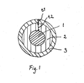
- Figure 1 shows a cross-section of an electrically insulated conductor 1 where the conductor in the form of a metallic wire is surrounded by an electrical insulation system comprising a first electrical insulation layer 2, comprising a polymer matrix with well dispersed nanoparticles of silica.
- the silica is grafted to the polymer matrix, for example, polyester or polyesterimide (PEI).
- PEI polyester or polyesterimide
- the nanoparticles have an average particle size of 1-200 nm.
- a second electrical insulation layer 3 comprising a polymer matrix of polyesteramide filled with chromium oxide (Cr 2 O 3 ) having an average particle size of 0.15-10 ⁇ m is surrounding the first insulation layer.
- the metallic wire according to this embodiment has a round cross section and is made of copper; however other forms of the conductor, such as profiled wire, and other conventional conductor materials, such as aluminium may also be used.
- the coating is applied in a conventional manner letting the wire pass multiple times through a coating bath comprising a varnish with filler, subsequent wiping dies or felts, and a heating device for curing the coating.
- a coating bath comprising a varnish with filler, subsequent wiping dies or felts, and a heating device for curing the coating.
- the wire is typically passed through the coating bath comprising a varnish of the first polymer and the well dispersed nano-particles, and thereafter the subsequent wiping and heating steps. This is repeated 8-12 times, such that a thickness (t1) of 20-120 ⁇ m is obtained for the first insulation layer.
- the second insulation layer 3 is applied in a corresponding way by letting the wire with the first insulation layer 1 pass through a coating bath with the varnish of the second polymer and the second filler, typically chrome oxide, and thereafter the subsequent wiping and heating steps. This is repeated 2-3 times, such that a thickness (t2) of 5-50 ⁇ m is obtained for the second layer.
- the number of coatings layers for of the first insulation layer 2 and the second insulation layer 3 depends on the voltage level on the motor for which the enamelled wire is to be used.
- the total thickness of the insulation layer for an enamelled wire is usually referred to as a specific insulation grade.
- the first insulation layer 2 is applied directly on the metallic wire by coating the wire with the varnish, however, also an intermediate surrounding layer may be arranged between the conductor 1 and the first insulation layer 2 for increasing the adhesion between the conductor and the insulation system.
- a third insulating layer (not shown) is arranged outside and surrounding the second insulation layer 3.
- the third layer can be applied directly on the second layer and mechanically protects the second insulating layer.
- the third insulating layer can be made of an unfilled polymer and the polymer is preferably of the same type as the second layer, i.e. any of the following: polyesters, polyesterimides, polyesteramide, polyamideimides, polyimides, polyurethanes, epoxy and polyamides.
- the graph in figure 2 shows lifetime curves of four different enamelled wires, based on generically different insulating coatings.
- Curve 1 is related to an enamelled wire with conventional base coating and a conventional top coating.
- Curve 2 is related to an enamelled wire with nano-filled base coating and a conventional top coating.
- Curve 3 is related to an enamelled wire with a conventional base coating with a corona protective top coating, i.e. a coating comprising chromium oxide and/or iron oxide filler.
- Curve 4 is related to an enamelled wire with a nano-filled base coating and a corona protective top coating.
- the nano-filled base-coating can be a coating according to the embodiment disclosed in relation to figure 1 .
- the lifetime curves are based on measurements of the time to breakdown of twisted pairs of round wires with a conductor diameter of 1.12 mm and insulation grade 2 at 50 Hz AC voltage and at 140°C.
- the applied voltage stress has been above the Partial Discharge Inception Voltage (PDIV) in all cases.
- the lifetime curves have been curve fitted to experimental data.
- the bending test was performed by bending the samples over a 2 mm test bend former to a coil with several turns. Thereafter the samples were aged in a furnace at 200°C during 48 hours. After the aging the surface of the samples were inspected and it was shown that Sample A and sample C had no cracks at the outer surface of the enamelled layer, while Sample B had cracks at the outer surface of the enamelled layer. It is believed that for sample A the nano-filled first insulation layer arranged under the second insulation layer distribute the mechanical stress in the insulation layers such that enamelled layer is less prone to cracking.
- the invention is not limited to the embodiments shown above, but the person skilled in the art may, of course, modify them in a plurality of ways within the scope of the invention as defined by the claims.
- the invention is not limited to conductor wires with a round cross-section as shown in the above two embodiments, but may be applied to conductors in the form of a rod, band, or bar, i.e. the conductor is elongated with a round or multi-corner constant cross-section.
- the insulted conductor may be used in windings for electrical motors, electrical transformers and other electrical equipment in which the insulation of the conductor can be exposed to corona discharges.
Landscapes
- Engineering & Computer Science (AREA)
- Power Engineering (AREA)
- Chemical & Material Sciences (AREA)
- Physics & Mathematics (AREA)
- Spectroscopy & Molecular Physics (AREA)
- Ceramic Engineering (AREA)
- Inorganic Chemistry (AREA)
- Insulation, Fastening Of Motor, Generator Windings (AREA)
- Insulated Conductors (AREA)
- Organic Insulating Materials (AREA)
- Inorganic Insulating Materials (AREA)
Description
- The present invention relates to an electrical conductor provided with a surrounding electrical insulation system.
- Electrical conductors provided with an electrical insulation in the form of a varnish filled with particles of chromium oxide (Cr2O3) or iron oxide (Fe2O3) are known to provide excellent resistance against partial discharges. These types of insulated electrical conductors are typically used in electrical motors and are then referred to as enamelled wires.
-
EP 356 929 A1 -
WO200536563A2 - Especially for low-voltage frequency-converter controlled motors there are increased requirements on the conductor insulation coating to withstand flash-over voltages that can give rise to partial discharges in the insulation system of the conductor, and subsequently possible electrical erosion of the insulation system. There is therefore a need for an electrical insulation system for metallic conductors, such as wires, that have a similar or higher resistance against partial discharges than insulation systems of today.
- One object of the invention is to provide an insulated electrical conductor with high resistance against partial discharges in the electrical insulation system. Another object of the invention is to improve the mechanical performances of the electrical insulation system of the insulated electrical conductor.
- Those objects are achieved by providing an electrical conductor provided with an electrical insulation system surrounding the conductor, the insulation system comprises a first electrical insulation layer surrounding the conductor and a second electrical insulation layer surrounding the first insulation layer. The second insulation layer comprises a second polymer and a second filler in the form of chromium oxide (Cr2O3), iron oxide (Fe2O3) or a mixture of chromium oxide and iron oxide, wherein the first insulation layer comprises a first polymer and a first filler comprising dispersed nanoparticles.
- The nanoparticles are preferably well-dispersed in the first polymer, which means that the dispersion of the nano-particles in the first polymer can be conducted in any conventional way, as long as the dispersion is carried out such that agglomeration is minimized and the nanoparticles are substantially homogenously distributed in first polymer.
- By an insulation system combining the first insulation layer with well dispersed nanoparticles and the second insulation layer filled with chromium oxide particles and/or iron oxide particles an excellent shield and resistance of the insulation system against electrical discharges is obtained and thereby an increased life time of the insulated conductors. The chromium oxide and/or iron oxide filler is believed to increase the electrical conductivity in the surface layer of the first insulation layer sufficiently for the extremely concentrated effect of a corona discharge to be dissipated over a large surface, thus reducing the effect of the corona discharge considerably.
- Further, the bending strength of the electrical insulation system is improved compared to prior art conductors having an insulation system of a chromium oxide and/or iron oxide filled polymer matrix. The first electrical insulation layer comprising nanoparticles arranged between the conductor and the second electrical insulation layer is more ductile than the second insulation layer and will therefore improve the flexibility of the entire electrical insulation system.
- The first electrical insulation layer comprising nanoparticles would also make it possible to use a lower chromium oxide and/or iron oxide content in the second insulation layer than in known insulation systems comprising chromium oxide and/or iron oxide, because even if the second electrical insulation layer is cracked due to partial discharges, the first insulation layer, i.e. the layer located between the conductor and the second insulation layer, will still give the insulation system a high resistance against partial discharges.
- According to one embodiment the second filler of chromium oxide and/or iron oxide is present in an amount of 10-40 % of the volume of the second insulation layer, preferably 10-30 % of the volume of the second insulation layer. Thereby an improved shielding against partial discharges is obtained and also an improved mechanical performance of the entire insulation system.
- According to one embodiment the second filler has an average particle size of 0.005-30 µm, preferably 0.010-15 µm, most preferably 0.15-10 µm. By this embodiment a further improved shielding against partial discharges is obtained.
- According to one embodiment the second filler has a resistivity of 104-108 ohm m.
- According to one embodiment the second polymer is at least one of the following polymers: polyesters, polyesterimides, polyamideimides, polyesteramides, polyimides, polyurethans, epoxy and polyamides.
- According to one embodiment the second insulation layer has a thickness of 5-50 µm.
- According to one embodiment the first polymer is at least one of the following polymers: polyesters, polyesterimides, polyamideimides, polyesteramides, polyimides, polyurethans, epoxy and polyamides.
- According to one embodiment of the invention the nanoparticles comprises at least any of the following: Silicon dioxide (Silica, SiO2), Aluminium oxide (Alumina, Al2O3), Zinc oxide (ZnO), Titanium dioxide (TiO2), Barium titanate (BaTiO3), Magnesium oxide (MgO) and Montmorillonite (MMT) clay.
- According to one embodiment the nanoparticles are grafted to the polymer matrix. The well dispersed and chemically bonded nanoparticles in the polymer matrix of the first insulation layer result in a further improved resistance against partial discharges as well as a ductile material with excellent bending strength. Upon mechanical deformation of the conductor, such as a wire, no voids are formed between the particles and the polymer matrix within the insulation layer. The absence of voids, in combination with the erosion-resistant filler, such as for example silicon dioxide (SiO2), results in low electrical erosion during partial discharges.
- According to one embodiment the nanoparticles in the first insulation layer are present in an amount of 1-40 % of the volume of the first layer. Thereby an improved resistance against partial discharges is obtained and also an improved mechanical performance of the entire insulation system. According to one embodiment the nanoparticles in the first insulation layer have an average particle size of 1-200 nm. Thereby an improved resistance against partial discharges is obtained and also an improved mechanical performance of insulation system.
- According to one embodiment the first insulation layer has a thickness of 20-120 µm.
- According to one embodiment the thickness of the second insulation layer is 10-25 %, preferably 15-20 % of the thickness of the first insulation layer. By this ratio between the first and second insulation layer the mechanical properties and bending strength of the insulation system is further improved.
- According to one embodiment the second insulation layer is surrounding the first insulation layer and is applied directly on the first insulation layer, such that it is in contact with the first insulation layer.
- According to one embodiment the insulation system is an enamelled insulation system.
- According to one embodiment an additional layer is arranged between the first insulation layer and the second insulation layer. The additional layer is, for example, applied to improve the adhesion between the first and second layer. According to one embodiment of the invention the additional layer has a thickness that is thinner than the first or second insulation layer.
- According to one embodiment an electrical motor with a winding or coil comprising an electrical conductor according to any of claims 1-14 is provided. The motor is preferably a low-voltage electrical motor. According to one embodiment the electrical motor is a low voltage frequency-converter controlled electrical motor. According to one embodiment a transformer is provided with a winding comprising an electrical conductor according to any of claims 1-14. As the electrical conductor according to any of the above described embodiments has proven to have excellent resistance against partial discharges, the properties of an electrical motor, transformer or other electrical equipment comprising a coil or winding of the electrical conductor will also be improved.
- The invention will be explained in greater detail by description of embodiments with reference to the accompanying drawings, wherein
- Figure 1
- is a cross-section of an insulated conductor according to a first embodiment of the present invention, and
- Figure 2
- is a diagram showing lifetime curves for four different types of enamelled wires.
-
Figure 1 shows a cross-section of an electricallyinsulated conductor 1 where the conductor in the form of a metallic wire is surrounded by an electrical insulation system comprising a firstelectrical insulation layer 2, comprising a polymer matrix with well dispersed nanoparticles of silica. The silica is grafted to the polymer matrix, for example, polyester or polyesterimide (PEI). The nanoparticles have an average particle size of 1-200 nm. - A second
electrical insulation layer 3 comprising a polymer matrix of polyesteramide filled with chromium oxide (Cr2O3) having an average particle size of 0.15-10 µm is surrounding the first insulation layer. - The metallic wire according to this embodiment has a round cross section and is made of copper; however other forms of the conductor, such as profiled wire, and other conventional conductor materials, such as aluminium may also be used.
- The coating is applied in a conventional manner letting the wire pass multiple times through a coating bath comprising a varnish with filler, subsequent wiping dies or felts, and a heating device for curing the coating. For applying the
first layer 2 on theconductor 1 the wire is typically passed through the coating bath comprising a varnish of the first polymer and the well dispersed nano-particles, and thereafter the subsequent wiping and heating steps. This is repeated 8-12 times, such that a thickness (t1) of 20-120 µm is obtained for the first insulation layer. - The
second insulation layer 3 is applied in a corresponding way by letting the wire with thefirst insulation layer 1 pass through a coating bath with the varnish of the second polymer and the second filler, typically chrome oxide, and thereafter the subsequent wiping and heating steps. This is repeated 2-3 times, such that a thickness (t2) of 5-50 µm is obtained for the second layer. - The number of coatings layers for of the
first insulation layer 2 and thesecond insulation layer 3 depends on the voltage level on the motor for which the enamelled wire is to be used. The total thickness of the insulation layer for an enamelled wire is usually referred to as a specific insulation grade. - In the embodiments according to
figure 1 thefirst insulation layer 2 is applied directly on the metallic wire by coating the wire with the varnish, however, also an intermediate surrounding layer may be arranged between theconductor 1 and thefirst insulation layer 2 for increasing the adhesion between the conductor and the insulation system. - According to another exemplary embodiment a third insulating layer (not shown) is arranged outside and surrounding the
second insulation layer 3. The third layer can be applied directly on the second layer and mechanically protects the second insulating layer. The third insulating layer can be made of an unfilled polymer and the polymer is preferably of the same type as the second layer, i.e. any of the following: polyesters, polyesterimides, polyesteramide, polyamideimides, polyimides, polyurethanes, epoxy and polyamides. - The graph in
figure 2 shows lifetime curves of four different enamelled wires, based on generically different insulating coatings.Curve 1 is related to an enamelled wire with conventional base coating and a conventional top coating.Curve 2 is related to an enamelled wire with nano-filled base coating and a conventional top coating.Curve 3 is related to an enamelled wire with a conventional base coating with a corona protective top coating, i.e. a coating comprising chromium oxide and/or iron oxide filler. Curve 4 is related to an enamelled wire with a nano-filled base coating and a corona protective top coating. The nano-filled base-coating can be a coating according to the embodiment disclosed in relation tofigure 1 . The lifetime curves are based on measurements of the time to breakdown of twisted pairs of round wires with a conductor diameter of 1.12 mm andinsulation grade 2 at 50 Hz AC voltage and at 140°C. The applied voltage stress has been above the Partial Discharge Inception Voltage (PDIV) in all cases. The lifetime curves have been curve fitted to experimental data. - From the curves in
figure 2 it can be seen that the enamelled wire with nano-filled base coating and corona protective top coating, curve 4, according to an embodiment of the invention clearly has the best voltage endurance performance, where its lifetime increases with decreasing voltage stress relative to the other types of wires. - It has also been shown in bending test that the mechanical properties of the enamelled wire is improved for an enamelled wire with a nano-filled base coating and a corona protective top coating, sample A, compared to an enamelled wire with a conventional base coating with a corona protective top coating, sample B. Also, an enamelled wire with a nano-filled base coating and a conventional top coating, sample C, was tested. All samples being made of enamelled round wires with a conductor diameter of 1.12 mm and
insulation grade 2. - The bending test was performed by bending the samples over a 2 mm test bend former to a coil with several turns. Thereafter the samples were aged in a furnace at 200°C during 48 hours. After the aging the surface of the samples were inspected and it was shown that Sample A and sample C had no cracks at the outer surface of the enamelled layer, while Sample B had cracks at the outer surface of the enamelled layer. It is believed that for sample A the nano-filled first insulation layer arranged under the second insulation layer distribute the mechanical stress in the insulation layers such that enamelled layer is less prone to cracking.
- The invention is not limited to the embodiments shown above, but the person skilled in the art may, of course, modify them in a plurality of ways within the scope of the invention as defined by the claims. Thus, the invention is not limited to conductor wires with a round cross-section as shown in the above two embodiments, but may be applied to conductors in the form of a rod, band, or bar, i.e. the conductor is elongated with a round or multi-corner constant cross-section. The insulted conductor may be used in windings for electrical motors, electrical transformers and other electrical equipment in which the insulation of the conductor can be exposed to corona discharges.
Claims (17)
- An electrical conductor (1) provided with an electrical insulation system surrounding the electrical conductor, the electrical insulation system comprises a first electrical insulation layer (2) surrounding the conductor and a second electrical insulation layer (3) surrounding the first electrical insulation layer (2), wherein the second electrical insulation layer (3) comprises a second polymer and a second filler in the form of chromium oxide (Cr2O3), iron oxide (Fe2O3), or a mixture of chromium oxide and iron oxide, characterized in that the first electrical insulation layer (2) comprises a first polymer and a first filler comprising dispersed nanoparticles.
- An electrical conductor according to claim 1, wherein the second filler is present in an amount of 10-40 % of the volume of the second electrical insulation layer, preferably 10-30 % of the volume of the second insulation layer.
- An electrical conductor according to claim 1 or 2, wherein the second insulation filler has an average particle size of 0.005-30 µm, preferably 0.010-15 µm, most preferably 0.15-10 µm.
- An electrical conductor according to any of the preceding claims, wherein the second insulation filler has a resistivity of 104-108 ohm m.
- An electrical conductor according to any of the preceding claims, wherein the second polymer is at least one of the following polymers: polyesters, polyesterimides, polyamideimides, polyesteramides, polyimides, polyurethanes, epoxy and polyamides.
- An electrical conductor according to any of the preceding claims, wherein the second insulation layer (3) has a thickness of 5-50 µm.
- An electrical conductor according to any of the preceding claims, wherein the first polymer of is at least one of the following polymers: polyesters, polyesterimides, polyamideimides, polyesteramides, polyimides, polyurethanes, epoxy and polyamides.
- An electrical conductor according to any of the preceding claims, wherein the nanoparticles are any of the following: Silicon dioxide, Aluminium oxide, Zinc oxide, Titanium dioxide, Barium titanate, Magnesium oxide and Montmorillonite clay.
- An electrical conductor according to any of the preceding claims, wherein the nanoparticles in the first electrical insulation layer (2) are present in an amount of 1-40 % of the volume of the first layer.
- An electrical conductor according to any of the preceding claims, wherein the nanoparticles in the first electrical insulation layer (2) have an average particle size of 1-200 nm.
- An electrical conductor according to any of the preceding claims, wherein the first electrical insulation layer (2) has a thickness (t1) of 20-120 µm
- An electrical conductor according to any of the preceding claims, wherein the thickness (t2) of the second electrical insulation layer (t2) is 10-25 %, preferably 15-20% of the thickness (t1) of the first electrical insulation layer.
- An electrical conductor according to any of preceding claims, wherein the electrical insulation system is an enamelled insulation system.
- An electrical conductor according to any of the preceding claims, wherein an additional layer is arranged between the first electrical insulation layer and the second electrical insulation layer.
- An electrical motor with a winding or coil comprising an electrical conductor according to any of claims 1-14.
- An electrical motor according to claim 15 wherein the electrical motor is a low voltage frequency-converter controlled electrical motor.
- A transformer with a winding comprising an electrical conductor according to any of claims 1-14.
Applications Claiming Priority (2)
| Application Number | Priority Date | Filing Date | Title |
|---|---|---|---|
| US35714210P | 2010-06-22 | 2010-06-22 | |
| PCT/EP2011/060332 WO2011161100A1 (en) | 2010-06-22 | 2011-06-21 | Electrical conductor with surrounding electrical insulation |
Publications (2)
| Publication Number | Publication Date |
|---|---|
| EP2586038A1 EP2586038A1 (en) | 2013-05-01 |
| EP2586038B1 true EP2586038B1 (en) | 2015-04-15 |
Family
ID=44356181
Family Applications (1)
| Application Number | Title | Priority Date | Filing Date |
|---|---|---|---|
| EP20110726786 Active EP2586038B1 (en) | 2010-06-22 | 2011-06-21 | Electrical conductor with surrounding electrical insulation |
Country Status (11)
| Country | Link |
|---|---|
| US (1) | US9019060B2 (en) |
| EP (1) | EP2586038B1 (en) |
| JP (1) | JP5889290B2 (en) |
| KR (1) | KR20130051980A (en) |
| CN (2) | CN106887280B (en) |
| AU (1) | AU2011269066B2 (en) |
| BR (1) | BR112012032363B1 (en) |
| CA (1) | CA2803142C (en) |
| MX (1) | MX2012014420A (en) |
| RS (1) | RS54142B1 (en) |
| WO (1) | WO2011161100A1 (en) |
Cited By (1)
| Publication number | Priority date | Publication date | Assignee | Title |
|---|---|---|---|---|
| EP4661032A1 (en) | 2024-06-03 | 2025-12-10 | Abb Schweiz Ag | Enamelled wire |
Families Citing this family (6)
| Publication number | Priority date | Publication date | Assignee | Title |
|---|---|---|---|---|
| EP2595157B1 (en) * | 2011-11-16 | 2018-01-10 | ABB Research Ltd. | Electrical insulation system |
| FR3008223B1 (en) * | 2013-07-08 | 2017-01-27 | Univ Paul Sabatier - Toulouse Iii | ELECTRICALLY INSULATING COMPOSITE MATERIAL, METHOD OF MANUFACTURING SUCH MATERIAL, AND ITS USE AS ELECTRIC INSULATION |
| US9728321B2 (en) * | 2015-01-22 | 2017-08-08 | Vladimir Viktorovich KAZAKOV | Transformer with ferromagnetic foil windings |
| WO2020086141A2 (en) * | 2018-08-13 | 2020-04-30 | University Of Connecticut | Nanostructured insulation for electric machines |
| MX2021015517A (en) | 2020-12-23 | 2022-06-24 | Weg Equipamentos Eletricos S A | Insulating wire with high thermal resistance and resistant to partial discharges and wire drawing process. |
| CN116760216A (en) * | 2023-05-05 | 2023-09-15 | 北京金风科创风电设备有限公司 | Coils, stators, forming methods, generators and wind turbines |
Family Cites Families (35)
| Publication number | Priority date | Publication date | Assignee | Title |
|---|---|---|---|---|
| US4760296A (en) | 1979-07-30 | 1988-07-26 | General Electric Company | Corona-resistant insulation, electrical conductors covered therewith and dynamoelectric machines and transformers incorporating components of such insulated conductors |
| SE457031B (en) * | 1987-03-24 | 1988-11-21 | Asea Ab | ELECTRIC conductor is provided with a surrounding insulation comprising a layer of an organic polymer and the use of the conductor in a harrow. |
| SE461941B (en) * | 1988-08-30 | 1990-04-09 | Asea Brown Boveri | ELECTRICAL conductor with a surround insulation and use of the conductor in a harness |
| US5468557A (en) * | 1989-01-12 | 1995-11-21 | Sumitomo Electric Industries, Ltd. | Ceramic insulated electrical conductor wire and method for manufacturing such a wire |
| US5372886A (en) * | 1989-03-28 | 1994-12-13 | Sumitomo Electric Industries, Ltd. | Insulated wire with an intermediate adhesion layer and an insulating layer |
| JPH0583936U (en) * | 1992-04-11 | 1993-11-12 | 株式会社フジクラ | Insulated wire |
| US6100474A (en) * | 1997-06-23 | 2000-08-08 | Essex Group, Inc. | Magnet wire insulation for inverter duty motors |
| DE19909954A1 (en) | 1999-03-06 | 2000-09-28 | Herberts Gmbh & Co Kg | Coating composition for metallic conductors and coating methods using them |
| JP3496636B2 (en) * | 2000-02-16 | 2004-02-16 | 日立電線株式会社 | Paint for partial discharge resistant enameled wire and partial discharge resistant enameled wire |
| JP3827196B2 (en) | 2001-05-01 | 2006-09-27 | 東京応化工業株式会社 | Photosensitive insulating paste composition and photosensitive film using the same |
| JP2003141946A (en) | 2001-11-02 | 2003-05-16 | Sumitomo Electric Ind Ltd | Superconducting cable |
| WO2003056575A1 (en) * | 2001-12-21 | 2003-07-10 | Pirelli Produtos Especiais Ltda | Pulsed voltage surge resistant magnet wire |
| CN1231923C (en) * | 2002-05-09 | 2005-12-14 | 上海大学 | Manufacturing method of pulse resistant surge voltage insulating material |
| DE10223354A1 (en) | 2002-05-25 | 2003-12-04 | Bosch Gmbh Robert | Fine wire for e.g. ignition coil winding, with insulation resisting partial breakdown, has primary insulation comprising lacquer coating |
| CN1242423C (en) * | 2003-05-29 | 2006-02-15 | 上海大学 | Manufacturing method of electromagnetic enamel-covered wire adaptable for variable frequency motor |
| DE10336747A1 (en) * | 2003-08-11 | 2005-03-17 | Infineon Technologies Ag | Semiconductor component used as a power transistor comprises a layer structure with a semiconductor chip, a support for the chip and an electrically insulating layer made from nano-particles of an electrically insulating material |
| US7923500B2 (en) * | 2003-08-21 | 2011-04-12 | Rensselaer Polytechnic Institute | Nanocomposites with controlled electrical properties |
| US6989173B2 (en) * | 2003-09-12 | 2006-01-24 | Siemens Westinghouse Power Corporation | Patching resins for insulating tapes |
| JP2005112908A (en) * | 2003-10-03 | 2005-04-28 | Totoku Electric Co Ltd | Inorganic filler dispersed insulating paint and insulated wire |
| US7875347B2 (en) | 2003-12-29 | 2011-01-25 | General Electric Company | Composite coatings for groundwall insulation, method of manufacture thereof and articles derived therefrom |
| JP4691883B2 (en) * | 2004-01-30 | 2011-06-01 | 富士ゼロックス株式会社 | Method for producing particles for display device |
| US7579397B2 (en) | 2005-01-27 | 2009-08-25 | Rensselaer Polytechnic Institute | Nanostructured dielectric composite materials |
| EP1899695B8 (en) | 2005-06-30 | 2012-06-27 | LED Roadway Lighting Ltd. | Method and system for luminance characterization |
| EP1814172A1 (en) * | 2006-01-27 | 2007-08-01 | IEE International Electronics & Engineering S.A.R.L. | Magnetic field sensing element |
| US20080143465A1 (en) * | 2006-12-15 | 2008-06-19 | General Electric Company | Insulation system and method for a transformer |
| JP2008251295A (en) * | 2007-03-29 | 2008-10-16 | Furukawa Electric Co Ltd:The | Insulated wire |
| CN101286384B (en) * | 2007-04-11 | 2010-12-29 | 清华大学 | Electromagnetic shielding cable |
| EP1983022A1 (en) | 2007-04-16 | 2008-10-22 | Altana Electrical Insulation GmbH | Nano-modified wire enamels and enamelled wires thereof |
| JP2009212034A (en) * | 2008-03-06 | 2009-09-17 | Hitachi Magnet Wire Corp | Varnish for partial discharge resistant enameled wire and partial discharge resistant enameled wire |
| MX2008013821A (en) | 2008-10-28 | 2010-04-28 | Magnekon S A De C V | Magnet wire with coating added with fullerene-type nanostructures. |
| CN102449010B (en) | 2009-04-10 | 2014-06-18 | 伦斯勒理工学院 | Nanoparticle-polymer nanocomposites modified by diblock copolymers for electrical insulators |
| CN101572455B (en) * | 2009-06-09 | 2011-06-08 | 上海电科电机科技有限公司 | Reinforced insulation structure applied to low-voltage variable frequency motor random winding |
| DE102009039454B4 (en) * | 2009-08-31 | 2018-06-28 | Siemens Aktiengesellschaft | Insulating |
| CN101719396B (en) * | 2009-12-29 | 2012-01-18 | 上海电缆研究所 | Radiation-resistant polyimide film insulating cable with high bonding strength and method for producing same |
| RU2547011C2 (en) * | 2010-01-29 | 2015-04-10 | Призмиан С.П.А. | Power cable |
-
2011
- 2011-06-21 BR BR112012032363-6A patent/BR112012032363B1/en not_active IP Right Cessation
- 2011-06-21 KR KR1020137000736A patent/KR20130051980A/en not_active Ceased
- 2011-06-21 EP EP20110726786 patent/EP2586038B1/en active Active
- 2011-06-21 RS RS20150466A patent/RS54142B1/en unknown
- 2011-06-21 AU AU2011269066A patent/AU2011269066B2/en not_active Ceased
- 2011-06-21 WO PCT/EP2011/060332 patent/WO2011161100A1/en not_active Ceased
- 2011-06-21 MX MX2012014420A patent/MX2012014420A/en active IP Right Grant
- 2011-06-21 CA CA2803142A patent/CA2803142C/en active Active
- 2011-06-21 CN CN201611037651.3A patent/CN106887280B/en not_active Expired - Fee Related
- 2011-06-21 JP JP2013515861A patent/JP5889290B2/en not_active Expired - Fee Related
- 2011-06-21 CN CN2011800292767A patent/CN102947894A/en active Pending
-
2012
- 2012-12-18 US US13/718,726 patent/US9019060B2/en not_active Expired - Fee Related
Cited By (1)
| Publication number | Priority date | Publication date | Assignee | Title |
|---|---|---|---|---|
| EP4661032A1 (en) | 2024-06-03 | 2025-12-10 | Abb Schweiz Ag | Enamelled wire |
Also Published As
| Publication number | Publication date |
|---|---|
| US20130099621A1 (en) | 2013-04-25 |
| US9019060B2 (en) | 2015-04-28 |
| JP5889290B2 (en) | 2016-03-22 |
| WO2011161100A1 (en) | 2011-12-29 |
| CA2803142A1 (en) | 2011-12-29 |
| BR112012032363B1 (en) | 2020-01-07 |
| MX2012014420A (en) | 2013-02-26 |
| AU2011269066A1 (en) | 2013-01-10 |
| CN102947894A (en) | 2013-02-27 |
| KR20130051980A (en) | 2013-05-21 |
| CN106887280A (en) | 2017-06-23 |
| AU2011269066B2 (en) | 2014-01-30 |
| JP2013535079A (en) | 2013-09-09 |
| RS54142B1 (en) | 2015-12-31 |
| EP2586038A1 (en) | 2013-05-01 |
| CA2803142C (en) | 2015-09-08 |
| CN106887280B (en) | 2018-12-04 |
| BR112012032363A2 (en) | 2016-11-08 |
Similar Documents
| Publication | Publication Date | Title |
|---|---|---|
| US9019060B2 (en) | Electrical conductor with surrounding electrical insulation | |
| US5861578A (en) | Electrical conductors coated with corona resistant, multilayer insulation system | |
| US10510459B2 (en) | Insulated winding wire articles having conformal coatings | |
| JP7541531B2 (en) | Magnet wire with thermoplastic insulation | |
| US20220199284A1 (en) | Insulating wire with high thermal resistance and resistant to partial discharges and wire drawing process | |
| CN112424879A (en) | Magnet wire with corona resistant polyimide insulator | |
| US20200251243A1 (en) | Magnet Wire With Improved Enamel Adhesion | |
| EP4270417A1 (en) | Magnet wire with corona resistant polyimide insulation | |
| CN118077022A (en) | Magnet wire with semi-conductive insulation | |
| WO2022165301A1 (en) | Magnet wire with high partial discharge inception voltage (pdiv) | |
| KR20230002294A (en) | heat-resistant insulated wire | |
| US11728067B2 (en) | Magnet wire with flexible corona resistant insulation | |
| EP4270418A1 (en) | Magnet wire with flexible corona resistant insulation | |
| US11728068B2 (en) | Magnet wire with corona resistant polyimide insulation | |
| US20250253093A1 (en) | Magnet wire with thermoplastic insulation | |
| CN104851480A (en) | Corona-resistant insulating winding wire |
Legal Events
| Date | Code | Title | Description |
|---|---|---|---|
| PUAI | Public reference made under article 153(3) epc to a published international application that has entered the european phase |
Free format text: ORIGINAL CODE: 0009012 |
|
| 17P | Request for examination filed |
Effective date: 20130122 |
|
| AK | Designated contracting states |
Kind code of ref document: A1 Designated state(s): AL AT BE BG CH CY CZ DE DK EE ES FI FR GB GR HR HU IE IS IT LI LT LU LV MC MK MT NL NO PL PT RO RS SE SI SK SM TR |
|
| DAX | Request for extension of the european patent (deleted) | ||
| 17Q | First examination report despatched |
Effective date: 20140410 |
|
| RIC1 | Information provided on ipc code assigned before grant |
Ipc: H01F 27/32 20060101ALI20141105BHEP Ipc: H01B 3/00 20060101ALI20141105BHEP Ipc: H01B 7/28 20060101ALI20141105BHEP Ipc: H01B 7/02 20060101ALI20141105BHEP Ipc: H01B 3/10 20060101AFI20141105BHEP Ipc: B82Y 30/00 20110101ALI20141105BHEP Ipc: H02K 3/30 20060101ALI20141105BHEP |
|
| GRAP | Despatch of communication of intention to grant a patent |
Free format text: ORIGINAL CODE: EPIDOSNIGR1 |
|
| INTG | Intention to grant announced |
Effective date: 20141218 |
|
| GRAS | Grant fee paid |
Free format text: ORIGINAL CODE: EPIDOSNIGR3 |
|
| GRAA | (expected) grant |
Free format text: ORIGINAL CODE: 0009210 |
|
| AK | Designated contracting states |
Kind code of ref document: B1 Designated state(s): AL AT BE BG CH CY CZ DE DK EE ES FI FR GB GR HR HU IE IS IT LI LT LU LV MC MK MT NL NO PL PT RO RS SE SI SK SM TR |
|
| REG | Reference to a national code |
Ref country code: GB Ref legal event code: FG4D Ref country code: CH Ref legal event code: EP |
|
| RAP2 | Party data changed (patent owner data changed or rights of a patent transferred) |
Owner name: ABB RESEARCH LTD |
|
| REG | Reference to a national code |
Ref country code: IE Ref legal event code: FG4D |
|
| REG | Reference to a national code |
Ref country code: AT Ref legal event code: REF Ref document number: 722372 Country of ref document: AT Kind code of ref document: T Effective date: 20150515 |
|
| REG | Reference to a national code |
Ref country code: DE Ref legal event code: R096 Ref document number: 602011015670 Country of ref document: DE Effective date: 20150528 |
|
| REG | Reference to a national code |
Ref country code: FR Ref legal event code: PLFP Year of fee payment: 5 |
|
| REG | Reference to a national code |
Ref country code: RO Ref legal event code: EPE |
|
| REG | Reference to a national code |
Ref country code: SE Ref legal event code: TRGR |
|
| REG | Reference to a national code |
Ref country code: NL Ref legal event code: VDEP Effective date: 20150415 |
|
| REG | Reference to a national code |
Ref country code: AT Ref legal event code: MK05 Ref document number: 722372 Country of ref document: AT Kind code of ref document: T Effective date: 20150415 |
|
| REG | Reference to a national code |
Ref country code: LT Ref legal event code: MG4D |
|
| PG25 | Lapsed in a contracting state [announced via postgrant information from national office to epo] |
Ref country code: NL Free format text: LAPSE BECAUSE OF FAILURE TO SUBMIT A TRANSLATION OF THE DESCRIPTION OR TO PAY THE FEE WITHIN THE PRESCRIBED TIME-LIMIT Effective date: 20150415 |
|
| PG25 | Lapsed in a contracting state [announced via postgrant information from national office to epo] |
Ref country code: PT Free format text: LAPSE BECAUSE OF FAILURE TO SUBMIT A TRANSLATION OF THE DESCRIPTION OR TO PAY THE FEE WITHIN THE PRESCRIBED TIME-LIMIT Effective date: 20150817 Ref country code: HR Free format text: LAPSE BECAUSE OF FAILURE TO SUBMIT A TRANSLATION OF THE DESCRIPTION OR TO PAY THE FEE WITHIN THE PRESCRIBED TIME-LIMIT Effective date: 20150415 Ref country code: ES Free format text: LAPSE BECAUSE OF FAILURE TO SUBMIT A TRANSLATION OF THE DESCRIPTION OR TO PAY THE FEE WITHIN THE PRESCRIBED TIME-LIMIT Effective date: 20150415 Ref country code: NO Free format text: LAPSE BECAUSE OF FAILURE TO SUBMIT A TRANSLATION OF THE DESCRIPTION OR TO PAY THE FEE WITHIN THE PRESCRIBED TIME-LIMIT Effective date: 20150715 Ref country code: LT Free format text: LAPSE BECAUSE OF FAILURE TO SUBMIT A TRANSLATION OF THE DESCRIPTION OR TO PAY THE FEE WITHIN THE PRESCRIBED TIME-LIMIT Effective date: 20150415 Ref country code: FI Free format text: LAPSE BECAUSE OF FAILURE TO SUBMIT A TRANSLATION OF THE DESCRIPTION OR TO PAY THE FEE WITHIN THE PRESCRIBED TIME-LIMIT Effective date: 20150415 |
|
| PG25 | Lapsed in a contracting state [announced via postgrant information from national office to epo] |
Ref country code: LV Free format text: LAPSE BECAUSE OF FAILURE TO SUBMIT A TRANSLATION OF THE DESCRIPTION OR TO PAY THE FEE WITHIN THE PRESCRIBED TIME-LIMIT Effective date: 20150415 Ref country code: AT Free format text: LAPSE BECAUSE OF FAILURE TO SUBMIT A TRANSLATION OF THE DESCRIPTION OR TO PAY THE FEE WITHIN THE PRESCRIBED TIME-LIMIT Effective date: 20150415 Ref country code: IS Free format text: LAPSE BECAUSE OF FAILURE TO SUBMIT A TRANSLATION OF THE DESCRIPTION OR TO PAY THE FEE WITHIN THE PRESCRIBED TIME-LIMIT Effective date: 20150815 Ref country code: GR Free format text: LAPSE BECAUSE OF FAILURE TO SUBMIT A TRANSLATION OF THE DESCRIPTION OR TO PAY THE FEE WITHIN THE PRESCRIBED TIME-LIMIT Effective date: 20150716 |
|
| REG | Reference to a national code |
Ref country code: DE Ref legal event code: R097 Ref document number: 602011015670 Country of ref document: DE |
|
| PG25 | Lapsed in a contracting state [announced via postgrant information from national office to epo] |
Ref country code: MC Free format text: LAPSE BECAUSE OF FAILURE TO SUBMIT A TRANSLATION OF THE DESCRIPTION OR TO PAY THE FEE WITHIN THE PRESCRIBED TIME-LIMIT Effective date: 20150415 Ref country code: EE Free format text: LAPSE BECAUSE OF FAILURE TO SUBMIT A TRANSLATION OF THE DESCRIPTION OR TO PAY THE FEE WITHIN THE PRESCRIBED TIME-LIMIT Effective date: 20150415 Ref country code: IT Free format text: LAPSE BECAUSE OF FAILURE TO SUBMIT A TRANSLATION OF THE DESCRIPTION OR TO PAY THE FEE WITHIN THE PRESCRIBED TIME-LIMIT Effective date: 20150415 Ref country code: DK Free format text: LAPSE BECAUSE OF FAILURE TO SUBMIT A TRANSLATION OF THE DESCRIPTION OR TO PAY THE FEE WITHIN THE PRESCRIBED TIME-LIMIT Effective date: 20150415 |
|
| PLBE | No opposition filed within time limit |
Free format text: ORIGINAL CODE: 0009261 |
|
| STAA | Information on the status of an ep patent application or granted ep patent |
Free format text: STATUS: NO OPPOSITION FILED WITHIN TIME LIMIT |
|
| PG25 | Lapsed in a contracting state [announced via postgrant information from national office to epo] |
Ref country code: CZ Free format text: LAPSE BECAUSE OF FAILURE TO SUBMIT A TRANSLATION OF THE DESCRIPTION OR TO PAY THE FEE WITHIN THE PRESCRIBED TIME-LIMIT Effective date: 20150415 Ref country code: PL Free format text: LAPSE BECAUSE OF FAILURE TO SUBMIT A TRANSLATION OF THE DESCRIPTION OR TO PAY THE FEE WITHIN THE PRESCRIBED TIME-LIMIT Effective date: 20150415 Ref country code: SK Free format text: LAPSE BECAUSE OF FAILURE TO SUBMIT A TRANSLATION OF THE DESCRIPTION OR TO PAY THE FEE WITHIN THE PRESCRIBED TIME-LIMIT Effective date: 20150415 Ref country code: LU Free format text: LAPSE BECAUSE OF FAILURE TO SUBMIT A TRANSLATION OF THE DESCRIPTION OR TO PAY THE FEE WITHIN THE PRESCRIBED TIME-LIMIT Effective date: 20150621 |
|
| 26N | No opposition filed |
Effective date: 20160118 |
|
| REG | Reference to a national code |
Ref country code: IE Ref legal event code: MM4A |
|
| PG25 | Lapsed in a contracting state [announced via postgrant information from national office to epo] |
Ref country code: IE Free format text: LAPSE BECAUSE OF NON-PAYMENT OF DUE FEES Effective date: 20150621 |
|
| PG25 | Lapsed in a contracting state [announced via postgrant information from national office to epo] |
Ref country code: SI Free format text: LAPSE BECAUSE OF FAILURE TO SUBMIT A TRANSLATION OF THE DESCRIPTION OR TO PAY THE FEE WITHIN THE PRESCRIBED TIME-LIMIT Effective date: 20150415 |
|
| REG | Reference to a national code |
Ref country code: FR Ref legal event code: PLFP Year of fee payment: 6 |
|
| PG25 | Lapsed in a contracting state [announced via postgrant information from national office to epo] |
Ref country code: MT Free format text: LAPSE BECAUSE OF FAILURE TO SUBMIT A TRANSLATION OF THE DESCRIPTION OR TO PAY THE FEE WITHIN THE PRESCRIBED TIME-LIMIT Effective date: 20150415 |
|
| PG25 | Lapsed in a contracting state [announced via postgrant information from national office to epo] |
Ref country code: BG Free format text: LAPSE BECAUSE OF FAILURE TO SUBMIT A TRANSLATION OF THE DESCRIPTION OR TO PAY THE FEE WITHIN THE PRESCRIBED TIME-LIMIT Effective date: 20150415 Ref country code: SM Free format text: LAPSE BECAUSE OF FAILURE TO SUBMIT A TRANSLATION OF THE DESCRIPTION OR TO PAY THE FEE WITHIN THE PRESCRIBED TIME-LIMIT Effective date: 20150415 Ref country code: HU Free format text: LAPSE BECAUSE OF FAILURE TO SUBMIT A TRANSLATION OF THE DESCRIPTION OR TO PAY THE FEE WITHIN THE PRESCRIBED TIME-LIMIT; INVALID AB INITIO Effective date: 20110621 |
|
| REG | Reference to a national code |
Ref country code: FR Ref legal event code: PLFP Year of fee payment: 7 |
|
| PG25 | Lapsed in a contracting state [announced via postgrant information from national office to epo] |
Ref country code: CY Free format text: LAPSE BECAUSE OF FAILURE TO SUBMIT A TRANSLATION OF THE DESCRIPTION OR TO PAY THE FEE WITHIN THE PRESCRIBED TIME-LIMIT Effective date: 20150415 |
|
| REG | Reference to a national code |
Ref country code: FR Ref legal event code: PLFP Year of fee payment: 8 |
|
| PG25 | Lapsed in a contracting state [announced via postgrant information from national office to epo] |
Ref country code: MK Free format text: LAPSE BECAUSE OF FAILURE TO SUBMIT A TRANSLATION OF THE DESCRIPTION OR TO PAY THE FEE WITHIN THE PRESCRIBED TIME-LIMIT Effective date: 20150415 |
|
| PG25 | Lapsed in a contracting state [announced via postgrant information from national office to epo] |
Ref country code: AL Free format text: LAPSE BECAUSE OF FAILURE TO SUBMIT A TRANSLATION OF THE DESCRIPTION OR TO PAY THE FEE WITHIN THE PRESCRIBED TIME-LIMIT Effective date: 20150415 |
|
| REG | Reference to a national code |
Ref country code: CH Ref legal event code: PFUS Owner name: ABB SCHWEIZ AG, CH Free format text: FORMER OWNER: ABB RESEARCH LTD., CH |
|
| REG | Reference to a national code |
Ref country code: BE Ref legal event code: PD Owner name: ABB SCHWEIZ AG; CH Free format text: DETAILS ASSIGNMENT: CHANGE OF OWNER(S), FUSION; FORMER OWNER NAME: ABB RESEARCH LTD. Effective date: 20191010 |
|
| REG | Reference to a national code |
Ref country code: DE Ref legal event code: R081 Ref document number: 602011015670 Country of ref document: DE Owner name: ABB SCHWEIZ AG, CH Free format text: FORMER OWNER: ABB RESEARCH LTD., ZUERICH, CH |
|
| PGFP | Annual fee paid to national office [announced via postgrant information from national office to epo] |
Ref country code: SE Payment date: 20220620 Year of fee payment: 12 Ref country code: RS Payment date: 20220614 Year of fee payment: 12 Ref country code: RO Payment date: 20220609 Year of fee payment: 12 Ref country code: GB Payment date: 20220627 Year of fee payment: 12 |
|
| PGFP | Annual fee paid to national office [announced via postgrant information from national office to epo] |
Ref country code: TR Payment date: 20220620 Year of fee payment: 12 Ref country code: BE Payment date: 20220620 Year of fee payment: 12 |
|
| PGFP | Annual fee paid to national office [announced via postgrant information from national office to epo] |
Ref country code: FR Payment date: 20220628 Year of fee payment: 12 |
|
| PGFP | Annual fee paid to national office [announced via postgrant information from national office to epo] |
Ref country code: DE Payment date: 20220620 Year of fee payment: 12 |
|
| PGFP | Annual fee paid to national office [announced via postgrant information from national office to epo] |
Ref country code: CH Payment date: 20220701 Year of fee payment: 12 |
|
| REG | Reference to a national code |
Ref country code: DE Ref legal event code: R119 Ref document number: 602011015670 Country of ref document: DE |
|
| REG | Reference to a national code |
Ref country code: SE Ref legal event code: EUG |
|
| PG25 | Lapsed in a contracting state [announced via postgrant information from national office to epo] |
Ref country code: RS Free format text: LAPSE BECAUSE OF NON-PAYMENT OF DUE FEES Effective date: 20230621 Ref country code: RO Free format text: LAPSE BECAUSE OF NON-PAYMENT OF DUE FEES Effective date: 20230621 |
|
| REG | Reference to a national code |
Ref country code: CH Ref legal event code: PL |
|
| REG | Reference to a national code |
Ref country code: BE Ref legal event code: MM Effective date: 20230630 |
|
| GBPC | Gb: european patent ceased through non-payment of renewal fee |
Effective date: 20230621 |
|
| PG25 | Lapsed in a contracting state [announced via postgrant information from national office to epo] |
Ref country code: DE Free format text: LAPSE BECAUSE OF NON-PAYMENT OF DUE FEES Effective date: 20240103 Ref country code: CH Free format text: LAPSE BECAUSE OF NON-PAYMENT OF DUE FEES Effective date: 20230630 Ref country code: GB Free format text: LAPSE BECAUSE OF NON-PAYMENT OF DUE FEES Effective date: 20230621 |
|
| PG25 | Lapsed in a contracting state [announced via postgrant information from national office to epo] |
Ref country code: SE Free format text: LAPSE BECAUSE OF NON-PAYMENT OF DUE FEES Effective date: 20230622 Ref country code: FR Free format text: LAPSE BECAUSE OF NON-PAYMENT OF DUE FEES Effective date: 20230630 Ref country code: BE Free format text: LAPSE BECAUSE OF NON-PAYMENT OF DUE FEES Effective date: 20230630 |