EP2585385B1 - Oxygen scavenging system for a container - Google Patents
Oxygen scavenging system for a container Download PDFInfo
- Publication number
- EP2585385B1 EP2585385B1 EP11798972.3A EP11798972A EP2585385B1 EP 2585385 B1 EP2585385 B1 EP 2585385B1 EP 11798972 A EP11798972 A EP 11798972A EP 2585385 B1 EP2585385 B1 EP 2585385B1
- Authority
- EP
- European Patent Office
- Prior art keywords
- container
- closure
- insert member
- catalyst
- hydrogen
- Prior art date
- Legal status (The legal status is an assumption and is not a legal conclusion. Google has not performed a legal analysis and makes no representation as to the accuracy of the status listed.)
- Active
Links
Images





Classifications
-
- B—PERFORMING OPERATIONS; TRANSPORTING
- B01—PHYSICAL OR CHEMICAL PROCESSES OR APPARATUS IN GENERAL
- B01J—CHEMICAL OR PHYSICAL PROCESSES, e.g. CATALYSIS OR COLLOID CHEMISTRY; THEIR RELEVANT APPARATUS
- B01J7/00—Apparatus for generating gases
- B01J7/02—Apparatus for generating gases by wet methods
-
- B—PERFORMING OPERATIONS; TRANSPORTING
- B01—PHYSICAL OR CHEMICAL PROCESSES OR APPARATUS IN GENERAL
- B01J—CHEMICAL OR PHYSICAL PROCESSES, e.g. CATALYSIS OR COLLOID CHEMISTRY; THEIR RELEVANT APPARATUS
- B01J19/00—Chemical, physical or physico-chemical processes in general; Their relevant apparatus
- B01J19/24—Stationary reactors without moving elements inside
- B01J19/245—Stationary reactors without moving elements inside placed in series
-
- B—PERFORMING OPERATIONS; TRANSPORTING
- B65—CONVEYING; PACKING; STORING; HANDLING THIN OR FILAMENTARY MATERIAL
- B65D—CONTAINERS FOR STORAGE OR TRANSPORT OF ARTICLES OR MATERIALS, e.g. BAGS, BARRELS, BOTTLES, BOXES, CANS, CARTONS, CRATES, DRUMS, JARS, TANKS, HOPPERS, FORWARDING CONTAINERS; ACCESSORIES, CLOSURES, OR FITTINGS THEREFOR; PACKAGING ELEMENTS; PACKAGES
- B65D25/00—Details of other kinds or types of rigid or semi-rigid containers
- B65D25/02—Internal fittings
-
- B—PERFORMING OPERATIONS; TRANSPORTING
- B65—CONVEYING; PACKING; STORING; HANDLING THIN OR FILAMENTARY MATERIAL
- B65D—CONTAINERS FOR STORAGE OR TRANSPORT OF ARTICLES OR MATERIALS, e.g. BAGS, BARRELS, BOTTLES, BOXES, CANS, CARTONS, CRATES, DRUMS, JARS, TANKS, HOPPERS, FORWARDING CONTAINERS; ACCESSORIES, CLOSURES, OR FITTINGS THEREFOR; PACKAGING ELEMENTS; PACKAGES
- B65D43/00—Lids or covers for rigid or semi-rigid containers
- B65D43/02—Removable lids or covers
-
- B—PERFORMING OPERATIONS; TRANSPORTING
- B65—CONVEYING; PACKING; STORING; HANDLING THIN OR FILAMENTARY MATERIAL
- B65D—CONTAINERS FOR STORAGE OR TRANSPORT OF ARTICLES OR MATERIALS, e.g. BAGS, BARRELS, BOTTLES, BOXES, CANS, CARTONS, CRATES, DRUMS, JARS, TANKS, HOPPERS, FORWARDING CONTAINERS; ACCESSORIES, CLOSURES, OR FITTINGS THEREFOR; PACKAGING ELEMENTS; PACKAGES
- B65D81/00—Containers, packaging elements, or packages, for contents presenting particular transport or storage problems, or adapted to be used for non-packaging purposes after removal of contents
- B65D81/24—Adaptations for preventing deterioration or decay of contents; Applications to the container or packaging material of food preservatives, fungicides, pesticides or animal repellants
- B65D81/26—Adaptations for preventing deterioration or decay of contents; Applications to the container or packaging material of food preservatives, fungicides, pesticides or animal repellants with provision for draining away, or absorbing, or removing by ventilation, fluids, e.g. exuded by contents; Applications of corrosion inhibitors or desiccators
- B65D81/266—Adaptations for preventing deterioration or decay of contents; Applications to the container or packaging material of food preservatives, fungicides, pesticides or animal repellants with provision for draining away, or absorbing, or removing by ventilation, fluids, e.g. exuded by contents; Applications of corrosion inhibitors or desiccators for absorbing gases, e.g. oxygen absorbers or desiccants
-
- C—CHEMISTRY; METALLURGY
- C01—INORGANIC CHEMISTRY
- C01B—NON-METALLIC ELEMENTS; COMPOUNDS THEREOF; METALLOIDS OR COMPOUNDS THEREOF NOT COVERED BY SUBCLASS C01C
- C01B3/00—Hydrogen; Gaseous mixtures containing hydrogen; Separation of hydrogen from mixtures containing it; Purification of hydrogen; Reversible storage of hydrogen
- C01B3/02—Production of hydrogen; Production of gaseous mixtures containing hydrogen
- C01B3/06—Production of hydrogen; Production of gaseous mixtures containing hydrogen by reaction of inorganic compounds containing electro-positively bound hydrogen with inorganic reducing agents
- C01B3/065—Production of hydrogen; Production of gaseous mixtures containing hydrogen by reaction of inorganic compounds containing electro-positively bound hydrogen with inorganic reducing agents by reaction of inorganic compounds with hydrides
-
- C—CHEMISTRY; METALLURGY
- C01—INORGANIC CHEMISTRY
- C01B—NON-METALLIC ELEMENTS; COMPOUNDS THEREOF; METALLOIDS OR COMPOUNDS THEREOF NOT COVERED BY SUBCLASS C01C
- C01B5/00—Water
-
- B—PERFORMING OPERATIONS; TRANSPORTING
- B01—PHYSICAL OR CHEMICAL PROCESSES OR APPARATUS IN GENERAL
- B01J—CHEMICAL OR PHYSICAL PROCESSES, e.g. CATALYSIS OR COLLOID CHEMISTRY; THEIR RELEVANT APPARATUS
- B01J2219/00—Chemical, physical or physico-chemical processes in general; Their relevant apparatus
- B01J2219/24—Stationary reactors without moving elements inside
-
- Y—GENERAL TAGGING OF NEW TECHNOLOGICAL DEVELOPMENTS; GENERAL TAGGING OF CROSS-SECTIONAL TECHNOLOGIES SPANNING OVER SEVERAL SECTIONS OF THE IPC; TECHNICAL SUBJECTS COVERED BY FORMER USPC CROSS-REFERENCE ART COLLECTIONS [XRACs] AND DIGESTS
- Y02—TECHNOLOGIES OR APPLICATIONS FOR MITIGATION OR ADAPTATION AGAINST CLIMATE CHANGE
- Y02E—REDUCTION OF GREENHOUSE GAS [GHG] EMISSIONS, RELATED TO ENERGY GENERATION, TRANSMISSION OR DISTRIBUTION
- Y02E60/00—Enabling technologies; Technologies with a potential or indirect contribution to GHG emissions mitigation
- Y02E60/30—Hydrogen technology
- Y02E60/36—Hydrogen production from non-carbon containing sources, e.g. by water electrolysis
Definitions
- This disclosure generally relates to containers for retaining a commodity, such as a solid or liquid commodity. More specifically, this disclosure relates to a container having being suitable for receiving an oxygen scavenging system, such as a hydrogen generator and/or catalyst.
- an oxygen scavenging system such as a hydrogen generator and/or catalyst.
- PET containers are now being used more than ever to package numerous commodities previously supplied in glass containers.
- PET is a crystallizable polymer, meaning that it is available in an amorphous form or a semi-crystalline form.
- the ability of a PET container to maintain its material integrity relates to the percentage of the PET container in crystalline form, also known as the "crystallinity" of the PET container.
- PET is a poor barrier to oxygen.
- One of the main factors that limit the shelf life of foods and beverages (herein known as "fills") in PET containers is the ingress of oxygen through the walls of the container followed by oxidation of the fill.
- Many strategies have been employed to reduce the amount of oxygen in contact with food in PET containers. Some strategies include headspace replacement, which replaces oxygen in the headspace during packaging with an inert gas, such as N2 or C02. Alternative strategies include using package barrier coatings, such as chemical vapor deposited (CVD) aluminum or silicon. Still further, some strategies include the use of embedded barrier layers, such as multilayer packages, or PET barrier additives that create physical barriers to oxygen diffusion through the packaging (e.g., nylon, nanoclays). Finally, some strategies have used oxygen scavengers that react with oxygen in a predetermined way (e.g., oxidizable plastics, hydrogen gas, reactive metals & organic molecules) to minimize its effect, which usually requires the use of a catalyst.
- An example of oxygen reducing technology is available from ColorMatrix (International Publication Number WO 2008/090354 A1 ).
- the technology involves the slow release of hydrogen from the container using a hydrogen generator.
- the hydrogen subsequently reacts with oxygen in the presence of a metal catalyst to create water. Hydrogen that does not react with oxygen will slowly permeate out of the container.
- the ColorMatrix system is predicated on the chemical reaction between the hydrogen generator, such as sodium borohydride, and a catalyst.
- the hydrogen generator such as sodium borohydride
- a catalyst a catalyst for the generation of the molecular hydrogen
- placement of the sodium borohydride and water in the container can be critical.
- placement of the sodium borohydride, such as in the closure or closure shell of the container may limit the amount of water (i.e. moisture) reacting with the compound (i.e. sodium borohydride) because other components used in the container, namely HDPE and PP, may be hydrophobic and, thus, limit the permeability of water.
- Container manufacturers use mechanical processing and thermal processing to increase the PET polymer crystallinity of a container.
- Mechanical processing involves orienting the amorphous material to achieve strain hardening. This processing commonly involves stretching an injection molded PET preform along a longitudinal axis and expanding the PET preform along a transverse or radial axis to form a PET container. The combination promotes what manufacturers define as biaxial orientation of the molecular structure in the container.
- Manufacturers of PET containers currently use mechanical processing to produce PET containers having approximately 20% crystallinity in the container's sidewall.
- Thermal processing involves heating the material (either amorphous or semi-crystalline) to promote crystal growth.
- thermal processing of PET material results in a spherulitic morphology that interferes with the transmission of light. In other words, the resulting crystalline material is opaque, and thus, generally undesirable.
- thermal processing results in higher crystallinity and excellent clarity for those portions of the container having biaxial molecular orientation.
- the thermal processing of an oriented PET container typically includes blow molding a PET preform against a mold heated to a temperature of approximately 121°C - 177°C (approximately 250°F - 350°F (), and holding the blown container against the heated mold for approximately two (2) to five (5) seconds.
- Manufacturers of PET juice bottles, which must be hot-filled at approximately 85°C (185°F) currently use heat setting to produce PET bottles having an overall crystallinity in the range of approximately 25% -35%.
- a container according to the preamble of claim 1 is known from WO 2008/090354 A1 .
- the known container includes a closure which can be a cap including a plug.
- the plug may include one or more sources of hydrogen.
- US 3 419 400 A discloses a container for storing items, such as lunch meat, in an oxygen-free environment.
- the container includes a hydrogen generating material and a catalyst which can be provided in the container or between an inner layer and a middle layer of a wall of the container.
- an object of the invention to disclose an improved container having a closure member that comprises a hydrogenerating system that is integrated into the container in a suitable manner.
- a closure member that comprises a hydrogenerating system that is integrated into the container in a suitable manner.
- the sealing between the closure and the container shall not be effected by the release of hydrogen.
- a container having systems for receiving an oxygen scavenging system, such as a hydrogen generator and catalyst, disposed or otherwise incorporated in components of the container.
- the container further comprises a system for providing at least a portion of the hydrogen generator and/or catalyst in an area defined within the closure of the container for improved performance.
- Example embodiments will now be described more fully with reference to the accompanying drawings. Example embodiments are provided so that this disclosure will be thorough. Numerous specific details are set forth such as examples of specific components, devices, and methods, to provide a thorough understanding of embodiments of the present disclosure. It will be apparent to those skilled in the art that specific details need not be employed, that example embodiments may be embodied in many different forms and that neither should be construed to limit the scope of the disclosure.
- first, second, third, etc. may be used herein to describe various elements, components, regions, layers and/or sections, these elements, components, regions, layers and/or sections should not be limited by these terms. These terms may be only used to distinguish one element, component, region, layer or section from another region, layer or section. Terms such as “first,” “second,” and other numerical terms when used herein do not imply a sequence or order unless clearly indicated by the context. Thus, a first element, component, region, layer or section discussed below could be termed a second element, component, region, layer or section without departing from the teachings of the example embodiments.
- spatially relative terms such as “inner,” “outer,” “beneath”, “below”, “lower”, “above”, “upper” and the like, may be used herein for ease of description to describe one element or feature's relationship to another element(s) or feature(s) as illustrated in the figures.
- Spatially relative terms may be intended to encompass different orientations of the device in use or operation in addition to the orientation depicted in the figures. For example, if the device in the figures is turned over, elements described as “below” or “beneath” other elements or features would then be oriented “above” the other elements or features.
- the example term “below” can encompass both an orientation of above and below.
- the device may be otherwise oriented (rotated 90 degrees or at other orientations) and the spatially relative descriptors used herein interpreted accordingly.
- This disclosure provides for a container being made of PET and incorporating a hydrogen generator and catalyst component.
- the container of the present teachings controls and/or reduces the effect of oxygen penetrating the container material and entering the commodity or fill contained therein.
- the present teachings are directed to facilitating the generation of the molecular hydrogen in the hydrogen generator.
- thermoplastic container including reusable/disposable packages including resealable plastic bags, resealable containers, dried food containers (e.g., dried milk), drug containers, and oxygen-sensitive chemical packaging.
- the present teachings provide a plastic, e.g. polyethylene terephthalate (PET), container generally indicated at 10.
- the exemplary container 10 can be substantially elongated when viewed from a side.
- PET polyethylene terephthalate
- the following teachings of the present disclosure are applicable to other containers, such as rectangular, triangular, pentagonal, hexagonal, octagonal, polygonal, or square shaped containers, which may have different dimensions and volume capacities. It is also contemplated that other modifications can be made depending on the specific application and environmental requirements.
- container 10 has been designed to retain a commodity.
- the commodity may be in any form such as a solid or semi-solid product.
- a commodity may be introduced into the container during a thermal process, typically a hot-fill process.
- bottlers For hot-fill bottling applications, bottlers generally fill the container 10 with a product at an elevated temperature between approximately 68°C to 96°C (approximately 155°F to 205°F) and seal the container 10 with a closure before cooling.
- the plastic container 10 may be suitable for other high-temperature pasteurization or retort filling processes or other thermal processes as well.
- the commodity may be introduced into the container under ambient or cold temperatures.
- the exemplary plastic container 10 defines a body 12, and includes an upper portion 14 having a cylindrical sidewall 18 forming a finish 20. Integrally formed with the finish 20 and extending downward therefrom is a shoulder portion 22. The shoulder portion 22 merges into and provides a transition between the finish 20 and a sidewall portion 24. The sidewall portion 24 extends downward from the shoulder portion 22 to a base portion 28 having a base 30. In some embodiments, sidewall portion 24 can extend down and nearly abut base 30, thereby minimizing the overall area of base portion 28 such that there is not a discernable base portion 28 when exemplary container 10 is uprightly-placed on a surface.
- the exemplary container 10 may also have a neck 23.
- the neck 23 may have an extremely short height, that is, becoming a short extension from the finish 20, or an elongated height, extending between the finish 20 and the shoulder portion 22.
- the upper portion 14 can define an opening for filling and dispensing of a commodity stored therein.
- the container is shown as a drinking container, it should be appreciated that containers having different shapes, such as sidewalls and openings, can be made according to the principles of the present teachings.
- the finish 20 of the exemplary plastic container 10 may include a threaded region 46 having threads 48, a lower sealing ridge 50, and a support ring 51.
- the threaded region provides a means for attachment of a similarly threaded closure or cap 100 ( FIGS. 2-6 , 8, and 9 ).
- Alternatives may include other suitable devices that engage the finish 20 of the exemplary plastic container 10, such as a press-fit or snap-fit cap or a combi-closure system, or induction welded to foil for example.
- the closure or cap 100 engages the finish 20 to preferably provide a hermetical seal of the exemplary plastic container 10.
- the closure or cap 100 is preferably of a plastic or metal material conventional to the closure industry and suitable for subsequent thermal processing.
- the container 10, of the present teachings is directed to facilitating the generation of the molecular hydrogen in the hydrogen generator.
- some chemical reactions used for the generation of molecular hydrogen are predicated on the availability of water. Due to this need for water, in some embodiments, placement of the sodium borohydride and water in the container can be critical. Therefore, the present teachings provide apparatus and methods for providing sufficient water for use in the generation of molecular hydrogen by the hydrogen generator.
- the hydrogen generator may be placed in a liner material disposed in the underside of the closure.
- a liner material made from a polar material, such as EVA-based materials.
- the liner material is made from non-polar liner materials, such as the styrenic rubber materials (SEBS / SIBS / SEPS).
- closure technology of today is progressing such that closures can be provided in hot-fill or cold-fill applications without the need for internal liners.
- many of these new systems employ an inner bore seal to engage and seal the container along the inside diameter of the opening. Since these systems form an adequate seal without using a liner, the liner and/or liner area, typically defined by an area inside the closure, can be used for introducing system components for the hydrogen generator and/or catalyst.
- closure 100 is illustrated having an additive insert member 102 disposed in an underside 104 of closure 100.
- additive insert member 102 comprises the hydrogen generator, the chemical component and the catalyst.
- Closure 100 can comprise, in some embodiments, a body portion 106 having a top portion 108 and a circumferential, downwardly-extending side portion 110. Threads 112 can be disposed on an inner side of downwardly-extending side portion 110 of closure 100 for threadingly engaging corresponding threads 48 of finish 20 for sealing engagement therewith. Closure 100 can further comprise a circumferential, inwardly-offset seal 114 downwardly-extending from underside 104 for engaging an inner diameter of finish 20 to provide improved sealing engagement therewith.
- additive insert member 102 can be sized to fit within an area bound by the circumferential, inwardly-offset seal 114 and underside 104.
- Additive insert member 102 can be molded in place, in some embodiments. Additive insert member 102 can, thus, releases hydrogen without affecting the seal area of the closure.
- additive insert member 102 can be a punched-in liner or patch pad (discussed herein) containing the hydrogen generator and the catalyst.
- a retention feature 116 can be added along an inner side of the circumferential, inwardly-offset seal 114 for retention of additive insert member 102.
- additive insert member 102 can be mounted using any one of a number of known methods, including adhesives (such as EVA or maleic anhydride), press-fit, snap-fit, and the like.
- surface geometries 118 of additive insert member 102 can be used to affect the rate of hydrogen evolution from the closure liner. That is, in some embodiments, the increased surface area allows for more moisture to come into contact with the borohydride and thus releases more hydrogen at a given time. By adjusting the liner surface area through shape, depth, and the like, the hydrogen evolution rate can be tailored for a given package. Additionally, as seen in FIG. 5 , the size and/or length of circumferential, inwardly-offset seal 114 can be modified to accommodate a larger additive insert member 102 to enable effective use of the technology in smaller diameter closures and/or increased capacity.
- alternative closure and/or additive insert member 102 configurations are provided to permit varied performance characteristics. It should be appreciated from the foregoing that various layering techniques can be used to provide varied performance, delayed activation, and the like.
- additive insert member 102 can be in the form of a patch member 210.
- Patch member 210 can be appropriately sized and shaped to be applied or otherwise contained within the container 10 and/or closure 100. More particularly, as illustrated in FIG. 7 , patch member 210 can be an encapsulated pad or patch that is connectable, such as via molding, adhesive or other connection system, to the container 10 and/or closure 100.
- Patch member 210 may comprise a barrier member 212 having an interior volume 214 for receiving the additive insert member 102 therein.
- patch member 210 can comprise an adhesive 216 disposed on a side 218 generally adjacent interior volume 214 to permit application of the patch member 210 to container 10 and/or closure 100. Otherwise, patch member 210, having additive insert member 102, can be disposed and connection to the container 10 and/or closure 100 using other conventional methods or novel methods defined herein.
- patch member 210 can be applied to an interior surface of closure 100 such that patch member 210 is connected via adhesive 216 to a standard closure liner 220. It should be appreciated, however, that standard closure liner 220 is optional and, thus, can be removed such that patch member 210 is connected to closure 100 directly.
- patch member 210 can simply comprise additive insert member 102 disposed within a recess or volume 222 formed in closure 100.
- closure 100 can be molded such that a depression 222 is formed in an interior surface thereof, such as the uppermost surface 224.
- Depression 222 can be sized to receive additive insert member 102 therein such that a layer 226, such as a liner, can be molded over additive insert member 102 to contain or otherwise encapsulated within closure 100.
- patch member 210 can be applied to a combi-closure system type closure 100'.
- combi-system type closures typically employ a metallic central member 240 and a plastic retaining ring member (not shown).
- patch member 210 can be affixed to the metallic central member 240 such that it is generally centrally placed relative to central member 240 to permit and not otherwise impede the added barrier properties available from combi-closure systems.
- additive insert member 102 can be applied to the foil seal 300.
- additive insert member 102 can be part of patch member 210 that is applied directly to foil seal 300.
- patch member 210 can be adhesively bonded to foil seal 300.
- patch member 210 can be coupled such that a multilayer assembly 302 is disposed adjacent patch member 210.
- the patch member 210 can be affixed such that patch member 210 is coupled to a first layer 304, such as a weld material to PET finish; a second layer 306, such as a barrier layer; a third layer 308 , such as foil; and a fourth layer 310, such as a backing.
- additive insert member 102 can be incorporated and/or encapsulated such that it forms a multilayer assembly having first layer 304, such as a weld material to PET finish; additive insert member 102; a second layer 306, such as a barrier layer; a third layer 308 , such as foil; and a fourth layer 310, such as a backing, respectively. In this way, additive insert member 102 can be incorporated directly into the manufacture of the foil sheet.
- additive insert member 102 can be incorporated into a pull-tab type foil seal 300, which is also known as a peel-and-toss type seal.
- Pull-tab type foil seal 300 can comprise a peel and toss ring 302 coupled to a main body portion 304 at a ring overlap 306.
- Additive insert member 102 can be applied or incorporated into foil seal 300 as described herein.
- Pull-tab type foil seal 300 can further comprise an outer ring 308 disposed about the periphery thereof that bounds additive insert member 102 and provides, in some embodiment, increased integrity of foil seal 300 to ensure that upon removal the foil seal remains intact and does not cause accidental tearing or breach of additive insert member 102.
- additive insert member 102 can be applied as a spray coating, patch member, printed, or the like.
- additive insert member 102 can be printed upon the foil seal 300 ( FIG. 14 ) and/or combi-closure 100' ( FIG. 15 ).
- additive insert member 102 is printed upon the substrate using known printing techniques, such as ink jet printing, offset printing, silkscreening, and the like. It should be noted that other printing techniques can be used wherein the components of additive insert member 102 are prepared in liquid or powder form and thus suitable for printing using common printing techniques.
- the components of additive insert member 102 are permitted to permeate through the appropriate barrier into the headspace and/or commodity of the container.
- the combi-closure 100' it should be noted that additive insert member 102 can be printed directly upon the metallic central member 240.
- additive insert member 102 can be a canister or capsule 410.
- Canister 410 can comprise an enclosed structure, such as an enclosed cylinder, having additive insert member 102 contained therein.
- additive insert member 102 can comprise a plurality of additive insert member pellets 102'.
- Canister 410 can further comprise an adhesive 412, if desired, for mounting the canister 410 within container 10 and/or closure 100.
- canister 410 can be placed loosely within the container 10.
- canister 410 can be mounted to an interior bottom surface of container 10 and/or an interior surface of closure 100 using known sealing techniques such as ultrasonic welding, heat sealing, induction sealing, or the like. In this way, canister 410 can be used to easily and conveniently convert an existing container design to one having the benefits of the present teachings.
- Food grade markings can be placed on canister 410 to indicate that additive insert member 102 should not be eaten.
Landscapes
- Chemical & Material Sciences (AREA)
- Organic Chemistry (AREA)
- Engineering & Computer Science (AREA)
- Chemical Kinetics & Catalysis (AREA)
- Mechanical Engineering (AREA)
- Inorganic Chemistry (AREA)
- Health & Medical Sciences (AREA)
- Combustion & Propulsion (AREA)
- Food Science & Technology (AREA)
- General Health & Medical Sciences (AREA)
- Closures For Containers (AREA)
- Catalysts (AREA)
- Packages (AREA)
- Devices And Processes Conducted In The Presence Of Fluids And Solid Particles (AREA)
Description
- This disclosure generally relates to containers for retaining a commodity, such as a solid or liquid commodity. More specifically, this disclosure relates to a container having being suitable for receiving an oxygen scavenging system, such as a hydrogen generator and/or catalyst.
- This section provides background information related to the present disclosure which is not necessarily prior art.
- As a result of environmental and other concerns, plastic containers, more specifically polyester and even more specifically polyethylene terephthalate (PET) containers are now being used more than ever to package numerous commodities previously supplied in glass containers. Manufacturers and fillers, as well as consumers, have recognized that PET containers are lightweight, inexpensive, recyclable and manufacturable in large quantities.
- Blow-molded plastic containers have become commonplace in packaging numerous commodities. PET is a crystallizable polymer, meaning that it is available in an amorphous form or a semi-crystalline form. The ability of a PET container to maintain its material integrity relates to the percentage of the PET container in crystalline form, also known as the "crystallinity" of the PET container. The following equation defines the percentage of crystallinity as a volume fraction:

- Unfortunately, PET is a poor barrier to oxygen. One of the main factors that limit the shelf life of foods and beverages (herein known as "fills") in PET containers is the ingress of oxygen through the walls of the container followed by oxidation of the fill. Many strategies have been employed to reduce the amount of oxygen in contact with food in PET containers. Some strategies include headspace replacement, which replaces oxygen in the headspace during packaging with an inert gas, such as N2 or C02. Alternative strategies include using package barrier coatings, such as chemical vapor deposited (CVD) aluminum or silicon. Still further, some strategies include the use of embedded barrier layers, such as multilayer packages, or PET barrier additives that create physical barriers to oxygen diffusion through the packaging (e.g., nylon, nanoclays). Finally, some strategies have used oxygen scavengers that react with oxygen in a predetermined way (e.g., oxidizable plastics, hydrogen gas, reactive metals & organic molecules) to minimize its effect, which usually requires the use of a catalyst.
- An example of oxygen reducing technology is available from ColorMatrix (International Publication Number
WO 2008/090354 A1 ). The technology involves the slow release of hydrogen from the container using a hydrogen generator. The hydrogen subsequently reacts with oxygen in the presence of a metal catalyst to create water. Hydrogen that does not react with oxygen will slowly permeate out of the container. - However, the ColorMatrix system is predicated on the chemical reaction between the hydrogen generator, such as sodium borohydride, and a catalyst. Due to the need for water, in some embodiments, for the generation of the molecular hydrogen, placement of the sodium borohydride and water in the container can be critical. However, in some application, placement of the sodium borohydride, such as in the closure or closure shell of the container, may limit the amount of water (i.e. moisture) reacting with the compound (i.e. sodium borohydride) because other components used in the container, namely HDPE and PP, may be hydrophobic and, thus, limit the permeability of water.
- Container manufacturers use mechanical processing and thermal processing to increase the PET polymer crystallinity of a container. Mechanical processing involves orienting the amorphous material to achieve strain hardening. This processing commonly involves stretching an injection molded PET preform along a longitudinal axis and expanding the PET preform along a transverse or radial axis to form a PET container. The combination promotes what manufacturers define as biaxial orientation of the molecular structure in the container. Manufacturers of PET containers currently use mechanical processing to produce PET containers having approximately 20% crystallinity in the container's sidewall.
- Thermal processing involves heating the material (either amorphous or semi-crystalline) to promote crystal growth. On amorphous material, thermal processing of PET material results in a spherulitic morphology that interferes with the transmission of light. In other words, the resulting crystalline material is opaque, and thus, generally undesirable. Used after mechanical processing, however, thermal processing results in higher crystallinity and excellent clarity for those portions of the container having biaxial molecular orientation. The thermal processing of an oriented PET container, which is known as heat setting, typically includes blow molding a PET preform against a mold heated to a temperature of approximately 121°C - 177°C (approximately 250°F - 350°F (), and holding the blown container against the heated mold for approximately two (2) to five (5) seconds. Manufacturers of PET juice bottles, which must be hot-filled at approximately 85°C (185°F), currently use heat setting to produce PET bottles having an overall crystallinity in the range of approximately 25% -35%.
- A container according to the preamble of
claim 1 is known fromWO 2008/090354 A1 . The known container includes a closure which can be a cap including a plug. The plug may include one or more sources of hydrogen. - Further reference is made to
US 3 419 400 A which discloses a container for storing items, such as lunch meat, in an oxygen-free environment. The container includes a hydrogen generating material and a catalyst which can be provided in the container or between an inner layer and a middle layer of a wall of the container. - Further reference is made to
WO 2010/115992 A1 which claims an earlier priority than the present application which, however, is not pre-published und thus is relevent only under Art. 54 (3) EPC. - In view of this, it is an object of the invention to disclose an improved container having a closure member that comprises a hydrogenerating system that is integrated into the container in a suitable manner. In particular the sealing between the closure and the container shall not be effected by the release of hydrogen.
- This object is achieved by a container according to
claim 1. - This section provides a general summary of the disclosure, and is not a comprehensive disclosure of its full scope or all of its features.
- According to the principles of the present teachings, a container is provided having systems for receiving an oxygen scavenging system, such as a hydrogen generator and catalyst, disposed or otherwise incorporated in components of the container. The container further comprises a system for providing at least a portion of the hydrogen generator and/or catalyst in an area defined within the closure of the container for improved performance.
- Further areas of applicability will become apparent from the description provided herein. The description and specific examples in this summary are intended for purposes of illustration only and are not intended to limit the scope of the present disclosure.
- The drawings described herein are for illustrative purposes only of selected embodiments and not all possible implementations, and are not intended to limit the scope of the present disclosure.
-
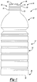
FIG. 1 is a side view of an exemplary container incorporating the features of the present teachings; -
FIG. 2 is a cross-sectional view of a closure according to some embodiments of the present teachings; -
FIG. 3 is a cross-sectional view of a closure according to some embodiments of the present teachings; -
FIG. 4A is a cross-sectional view of a closure according to some embodiments of the present teachings having an insert member defining a varied topography; -
FIG. 4B is a cross-sectional view of a closure according to some embodiments of the present teachings having an insert member defining a varied topography; -
FIG. 5 is a cross-sectional view of a closure according to some embodiments of the present teachings having an insert member defining an elongated dimension; -
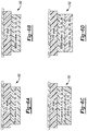
FIGS. 6A-6H are schematic cross-sectional views illustrating various combinations of materials which may be used with the insert member of the present teachings; -
FIG. 7 is a cross-sectional view of a patch pad according to some embodiments of the present teachings connectable to a surface; -
FIG. 8 is a cross-sectional view of a patch pad according to some embodiments of the present teachings disposed in a closure member; -
FIG. 9 is a cross-sectional view of a patch pad according to some embodiments of the present teachings recessed in a closure member; -
FIG. 10 is a top view of a patch pad according to some embodiments of the present teachings disposed on a combi-closure system; -
FIG. 11 is a cross-sectional view of a patch pad according to some embodiments of the present teachings disposed on a foil seal; -
FIG. 12 is a cross-sectional view of an additive insert member according to some embodiments of the present teachings incorporated into a foil seal; -
FIG. 13 is a top view of a patch pad according to some embodiments of the present teachings incorporated into a foil seal; -
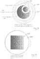
FIG. 14 is a top view of an additive insert member according to some embodiments of the present teachings printed on a foil seal; -
FIG. 15 is a top view of an additive insert member according to some embodiments of the present teachings printed on a combi-closure system; and -
FIG. 16 is a cross-sectional view of an additive insert member according to some embodiments of the present teachings in the form of a sealed canister. - Corresponding reference numerals indicate corresponding parts throughout the several views of the drawings.
- Example embodiments will now be described more fully with reference to the accompanying drawings. Example embodiments are provided so that this disclosure will be thorough. Numerous specific details are set forth such as examples of specific components, devices, and methods, to provide a thorough understanding of embodiments of the present disclosure. It will be apparent to those skilled in the art that specific details need not be employed, that example embodiments may be embodied in many different forms and that neither should be construed to limit the scope of the disclosure.
- The terminology used herein is for the purpose of describing particular example embodiments only and is not intended to be limiting. As used herein, the singular forms "a", "an" and "the" may be intended to include the plural forms as well, unless the context clearly indicates otherwise. The terms "comprises," "comprising," "including," and "having," are inclusive and therefore specify the presence of stated features, integers, steps, operations, elements, and/or components, but do not preclude the presence or addition of one or more other features, integers, steps, operations, elements, components, and/or groups thereof. The method steps, processes, and operations described herein are not to be construed as necessarily requiring their performance in the particular order discussed or illustrated, unless specifically identified as an order of performance. It is also to be understood that additional or alternative steps may be employed.
- When an element or layer is referred to as being "on", "engaged to", "connected to" or "coupled to" another element or layer, it may be directly on, engaged, connected or coupled to the other element or layer, or intervening elements or layers may be present. In contrast, when an element is referred to as being "directly on," "directly engaged to", "directly connected to" or "directly coupled to" another element or layer, there may be no intervening elements or layers present. Other words used to describe the relationship between elements should be interpreted in a like fashion (e.g., "between" versus "directly between," "adjacent" versus "directly adjacent," etc.). As used herein, the term "and/or" includes any and all combinations of one or more of the associated listed items.
- Although the terms first, second, third, etc. may be used herein to describe various elements, components, regions, layers and/or sections, these elements, components, regions, layers and/or sections should not be limited by these terms. These terms may be only used to distinguish one element, component, region, layer or section from another region, layer or section. Terms such as "first," "second," and other numerical terms when used herein do not imply a sequence or order unless clearly indicated by the context. Thus, a first element, component, region, layer or section discussed below could be termed a second element, component, region, layer or section without departing from the teachings of the example embodiments.
- Spatially relative terms, such as "inner," "outer," "beneath", "below", "lower", "above", "upper" and the like, may be used herein for ease of description to describe one element or feature's relationship to another element(s) or feature(s) as illustrated in the figures. Spatially relative terms may be intended to encompass different orientations of the device in use or operation in addition to the orientation depicted in the figures. For example, if the device in the figures is turned over, elements described as "below" or "beneath" other elements or features would then be oriented "above" the other elements or features. Thus, the example term "below" can encompass both an orientation of above and below. The device may be otherwise oriented (rotated 90 degrees or at other orientations) and the spatially relative descriptors used herein interpreted accordingly.
- This disclosure provides for a container being made of PET and incorporating a hydrogen generator and catalyst component. The container of the present teachings controls and/or reduces the effect of oxygen penetrating the container material and entering the commodity or fill contained therein. The present teachings are directed to facilitating the generation of the molecular hydrogen in the hydrogen generator.
- It should be appreciated that the size and specific configuration of the container may not be particularly limiting and, thus, the principles of the present teachings can be applicable to a wide variety of thermoplastic container shapes and system configurations. Therefore, it should be recognized that variations can exist in the present embodiments. That is, it should be appreciated that the teachings of the present disclosure can be used in a wide variety of thermoplastic containers, including reusable/disposable packages including resealable plastic bags, resealable containers, dried food containers (e.g., dried milk), drug containers, and oxygen-sensitive chemical packaging.
- Accordingly, the present teachings provide a plastic, e.g. polyethylene terephthalate (PET), container generally indicated at 10. The
exemplary container 10 can be substantially elongated when viewed from a side. Those of ordinary skill in the art would appreciate that the following teachings of the present disclosure are applicable to other containers, such as rectangular, triangular, pentagonal, hexagonal, octagonal, polygonal, or square shaped containers, which may have different dimensions and volume capacities. It is also contemplated that other modifications can be made depending on the specific application and environmental requirements. - In some embodiments,
container 10 has been designed to retain a commodity. The commodity may be in any form such as a solid or semi-solid product. In one example, a commodity may be introduced into the container during a thermal process, typically a hot-fill process. For hot-fill bottling applications, bottlers generally fill thecontainer 10 with a product at an elevated temperature between approximately 68°C to 96°C (approximately 155°F to 205°F) and seal thecontainer 10 with a closure before cooling. In addition, theplastic container 10 may be suitable for other high-temperature pasteurization or retort filling processes or other thermal processes as well. In another example, the commodity may be introduced into the container under ambient or cold temperatures. - As shown in
FIG. 1 , the exemplaryplastic container 10 according to the present teachings defines abody 12, and includes anupper portion 14 having acylindrical sidewall 18 forming afinish 20. Integrally formed with thefinish 20 and extending downward therefrom is ashoulder portion 22. Theshoulder portion 22 merges into and provides a transition between thefinish 20 and asidewall portion 24. Thesidewall portion 24 extends downward from theshoulder portion 22 to abase portion 28 having abase 30. In some embodiments,sidewall portion 24 can extend down and nearlyabut base 30, thereby minimizing the overall area ofbase portion 28 such that there is not adiscernable base portion 28 whenexemplary container 10 is uprightly-placed on a surface. - The
exemplary container 10 may also have aneck 23. Theneck 23 may have an extremely short height, that is, becoming a short extension from thefinish 20, or an elongated height, extending between thefinish 20 and theshoulder portion 22. Theupper portion 14 can define an opening for filling and dispensing of a commodity stored therein. Although the container is shown as a drinking container, it should be appreciated that containers having different shapes, such as sidewalls and openings, can be made according to the principles of the present teachings. - The
finish 20 of the exemplaryplastic container 10 may include a threaded region 46 havingthreads 48, alower sealing ridge 50, and asupport ring 51. The threaded region provides a means for attachment of a similarly threaded closure or cap 100 (FIGS. 2-6 ,8, and 9 ). Alternatives may include other suitable devices that engage thefinish 20 of the exemplaryplastic container 10, such as a press-fit or snap-fit cap or a combi-closure system, or induction welded to foil for example. Accordingly, the closure orcap 100 engages thefinish 20 to preferably provide a hermetical seal of the exemplaryplastic container 10. The closure orcap 100 is preferably of a plastic or metal material conventional to the closure industry and suitable for subsequent thermal processing. - The
container 10, of the present teachings, is directed to facilitating the generation of the molecular hydrogen in the hydrogen generator. As is known, as described herein, some chemical reactions used for the generation of molecular hydrogen are predicated on the availability of water. Due to this need for water, in some embodiments, placement of the sodium borohydride and water in the container can be critical. Therefore, the present teachings provide apparatus and methods for providing sufficient water for use in the generation of molecular hydrogen by the hydrogen generator. - In some embodiments, the hydrogen generator, perhaps in the form of sodium borohydride, may be placed in a liner material disposed in the underside of the closure. This may be a viable option with a liner material made from a polar material, such as EVA-based materials. However, it may be desirable when the liner material is made from non-polar liner materials, such as the styrenic rubber materials (SEBS / SIBS / SEPS).
- The closure technology of today is progressing such that closures can be provided in hot-fill or cold-fill applications without the need for internal liners. In hot-fill applications, many of these new systems employ an inner bore seal to engage and seal the container along the inside diameter of the opening. Since these systems form an adequate seal without using a liner, the liner and/or liner area, typically defined by an area inside the closure, can be used for introducing system components for the hydrogen generator and/or catalyst.
- With reference to
FIG. 2 ,closure 100 is illustrated having anadditive insert member 102 disposed in anunderside 104 ofclosure 100. According to the invention,additive insert member 102 comprises the hydrogen generator, the chemical component and the catalyst. -
Closure 100 can comprise, in some embodiments, abody portion 106 having atop portion 108 and a circumferential, downwardly-extendingside portion 110.Threads 112 can be disposed on an inner side of downwardly-extendingside portion 110 ofclosure 100 for threadingly engagingcorresponding threads 48 offinish 20 for sealing engagement therewith.Closure 100 can further comprise a circumferential, inwardly-offsetseal 114 downwardly-extending fromunderside 104 for engaging an inner diameter offinish 20 to provide improved sealing engagement therewith. - In some embodiments, as illustrated in
FIG. 2 ,additive insert member 102 can be sized to fit within an area bound by the circumferential, inwardly-offsetseal 114 andunderside 104.Additive insert member 102 can be molded in place, in some embodiments.Additive insert member 102 can, thus, releases hydrogen without affecting the seal area of the closure. - With reference to
FIG. 3 , in some embodimentsadditive insert member 102 can be a punched-in liner or patch pad (discussed herein) containing the hydrogen generator and the catalyst. Aretention feature 116 can be added along an inner side of the circumferential, inwardly-offsetseal 114 for retention ofadditive insert member 102. It should be understood that in some embodiments,additive insert member 102 can be mounted using any one of a number of known methods, including adhesives (such as EVA or maleic anhydride), press-fit, snap-fit, and the like. - Referring now to
FIGS. 4A and 4B , in some embodiments,surface geometries 118 ofadditive insert member 102 can be used to affect the rate of hydrogen evolution from the closure liner. That is, in some embodiments, the increased surface area allows for more moisture to come into contact with the borohydride and thus releases more hydrogen at a given time. By adjusting the liner surface area through shape, depth, and the like, the hydrogen evolution rate can be tailored for a given package. Additionally, as seen inFIG. 5 , the size and/or length of circumferential, inwardly-offsetseal 114 can be modified to accommodate a largeradditive insert member 102 to enable effective use of the technology in smaller diameter closures and/or increased capacity. - With reference to
FIGS. 6A-6H , alternative closure and/oradditive insert member 102 configurations are provided to permit varied performance characteristics. It should be appreciated from the foregoing that various layering techniques can be used to provide varied performance, delayed activation, and the like. - With particular reference to
FIGS. 7-9 , it should be understood thatadditive insert member 102 can be in the form of apatch member 210.Patch member 210 can be appropriately sized and shaped to be applied or otherwise contained within thecontainer 10 and/orclosure 100. More particularly, as illustrated inFIG. 7 ,patch member 210 can be an encapsulated pad or patch that is connectable, such as via molding, adhesive or other connection system, to thecontainer 10 and/orclosure 100.Patch member 210 may comprise abarrier member 212 having aninterior volume 214 for receiving theadditive insert member 102 therein. In some embodiments,patch member 210 can comprise an adhesive 216 disposed on a side 218 generally adjacentinterior volume 214 to permit application of thepatch member 210 tocontainer 10 and/orclosure 100. Otherwise,patch member 210, havingadditive insert member 102, can be disposed and connection to thecontainer 10 and/orclosure 100 using other conventional methods or novel methods defined herein. - As illustrated in
FIG. 8 ,patch member 210 can be applied to an interior surface ofclosure 100 such thatpatch member 210 is connected via adhesive 216 to astandard closure liner 220. It should be appreciated, however, thatstandard closure liner 220 is optional and, thus, can be removed such thatpatch member 210 is connected toclosure 100 directly. - In some embodiments, as illustrated in
FIG. 9 ,patch member 210 can simply compriseadditive insert member 102 disposed within a recess orvolume 222 formed inclosure 100. Specifically,closure 100 can be molded such that adepression 222 is formed in an interior surface thereof, such as theuppermost surface 224.Depression 222 can be sized to receiveadditive insert member 102 therein such that alayer 226, such as a liner, can be molded overadditive insert member 102 to contain or otherwise encapsulated withinclosure 100. - In some embodiments, as illustrated in
FIG. 10 ,patch member 210 can be applied to a combi-closure system type closure 100'. As is known, combi-system type closures typically employ a metalliccentral member 240 and a plastic retaining ring member (not shown). According to the present teachings,patch member 210 can be affixed to the metalliccentral member 240 such that it is generally centrally placed relative tocentral member 240 to permit and not otherwise impede the added barrier properties available from combi-closure systems. - Several containers available today employ an induction foil seal over the finish of the container to hermetically seal the contents of the container. In some embodiments, as illustrated in
FIGS. 11-13 ,additive insert member 102 can be applied to thefoil seal 300. Specifically, in some embodiments,additive insert member 102 can be part ofpatch member 210 that is applied directly to foilseal 300. In this way,patch member 210 can be adhesively bonded to foilseal 300. In some embodiments,patch member 210 can be coupled such that amultilayer assembly 302 is disposedadjacent patch member 210. Specifically, thepatch member 210 can be affixed such thatpatch member 210 is coupled to afirst layer 304, such as a weld material to PET finish; asecond layer 306, such as a barrier layer; athird layer 308 , such as foil; and afourth layer 310, such as a backing. However, in some embodiments, as illustrated inFIG. 12 ,additive insert member 102 can be incorporated and/or encapsulated such that it forms a multilayer assembly havingfirst layer 304, such as a weld material to PET finish;additive insert member 102; asecond layer 306, such as a barrier layer; athird layer 308 , such as foil; and afourth layer 310, such as a backing, respectively. In this way,additive insert member 102 can be incorporated directly into the manufacture of the foil sheet. - Alternatively, as illustrated in
FIG. 13 , in some embodiments,additive insert member 102 can be incorporated into a pull-tabtype foil seal 300, which is also known as a peel-and-toss type seal. Pull-tabtype foil seal 300 can comprise a peel and tossring 302 coupled to amain body portion 304 at aring overlap 306.Additive insert member 102 can be applied or incorporated intofoil seal 300 as described herein. Pull-tabtype foil seal 300 can further comprise anouter ring 308 disposed about the periphery thereof that boundsadditive insert member 102 and provides, in some embodiment, increased integrity offoil seal 300 to ensure that upon removal the foil seal remains intact and does not cause accidental tearing or breach ofadditive insert member 102. In some embodiments,additive insert member 102 can be applied as a spray coating, patch member, printed, or the like. - With reference to
FIGS. 14 and 15 , in some embodiments, not covered by the claims,additive insert member 102 can be printed upon the foil seal 300 (FIG. 14 ) and/or combi-closure 100' (FIG. 15 ). Specifically, in some embodiments,additive insert member 102 is printed upon the substrate using known printing techniques, such as ink jet printing, offset printing, silkscreening, and the like. It should be noted that other printing techniques can be used wherein the components ofadditive insert member 102 are prepared in liquid or powder form and thus suitable for printing using common printing techniques. Through the application ofadditive insert member 102 to foilseal 300, the components ofadditive insert member 102 are permitted to permeate through the appropriate barrier into the headspace and/or commodity of the container. With regard to the combi-closure 100', it should be noted thatadditive insert member 102 can be printed directly upon the metalliccentral member 240. - Finally, in some embodiments as illustrated in
FIG. 16 ,additive insert member 102 can be a canister orcapsule 410.Canister 410 can comprise an enclosed structure, such as an enclosed cylinder, havingadditive insert member 102 contained therein. In some embodiments,additive insert member 102 can comprise a plurality of additive insert member pellets 102'.Canister 410 can further comprise an adhesive 412, if desired, for mounting thecanister 410 withincontainer 10 and/orclosure 100. In some embodiments,canister 410 can be placed loosely within thecontainer 10. In some embodiments,canister 410 can be mounted to an interior bottom surface ofcontainer 10 and/or an interior surface ofclosure 100 using known sealing techniques such as ultrasonic welding, heat sealing, induction sealing, or the like. In this way,canister 410 can be used to easily and conveniently convert an existing container design to one having the benefits of the present teachings. Food grade markings can be placed oncanister 410 to indicate thatadditive insert member 102 should not be eaten. - The foregoing description of the embodiments has been provided for purposes of illustration and description. It is not intended to be exhaustive or to limit the invention. Individual elements or features of a particular embodiment are generally not limited to that particular embodiment, but, where applicable, are interchangeable and can be used in a selected embodiment, even if not specifically shown or described. The same may also be varied in many ways. Such variations are not to be regarded as a departure from the invention.
Claims (1)
- A container comprising:a body (12) having an interior volume, said body including an upper portion (14) having a cylindrical sidewall (18) having an inner diameter and defining a finish (20), wherein integrally formed with the finish (20) and extending downward therefrom is a shoulder portion (22) which merges into and provides a transition between the finish (20) and a sidewall portion (24), said sidewall portion (24) extending downward from the shoulder portion (22) to a base portion (28) having a base (30);a closure member (100, 100') engaging said body;a hydrogen generator generating molecular hydrogen;a catalyst catalyzing a chemical reaction between said hydrogen and oxygen; andan insert member (102) in communication with said interior volume of said body (12), said insert member (102) containing at least one of said hydrogen generator, said catalyst, and a chemical component for chemical reaction with either said hydrogen generator or said catalyst;wherein the container is made of PET;characterized in thatin that said insert member (102) is a lamination having a barrier member and at least one of said hydrogen generator, said catalyst, and said chemical component, said lamination being connected to said closure member,in that said lamination is disposed within a recess formed within said closure member (100, 100') and is overmolded with a liner layer, andin that said insert member (102) comprises each of said hydrogen generator, said chemical component and said catalyst.
Applications Claiming Priority (3)
| Application Number | Priority Date | Filing Date | Title |
|---|---|---|---|
| US35845610P | 2010-06-25 | 2010-06-25 | |
| US13/167,967 US9108176B2 (en) | 2010-06-25 | 2011-06-24 | Oxygen scavenging system for a container |
| PCT/US2011/041770 WO2011163562A2 (en) | 2010-06-25 | 2011-06-24 | Oxygen scavenging system for a container |
Publications (3)
| Publication Number | Publication Date |
|---|---|
| EP2585385A2 EP2585385A2 (en) | 2013-05-01 |
| EP2585385A4 EP2585385A4 (en) | 2014-01-15 |
| EP2585385B1 true EP2585385B1 (en) | 2019-12-18 |
Family
ID=45352754
Family Applications (1)
| Application Number | Title | Priority Date | Filing Date |
|---|---|---|---|
| EP11798972.3A Active EP2585385B1 (en) | 2010-06-25 | 2011-06-24 | Oxygen scavenging system for a container |
Country Status (7)
| Country | Link |
|---|---|
| US (2) | US9108176B2 (en) |
| EP (1) | EP2585385B1 (en) |
| BR (1) | BR112012032777B1 (en) |
| CA (1) | CA2803302C (en) |
| ES (1) | ES2773071T3 (en) |
| MX (4) | MX362176B (en) |
| WO (1) | WO2011163562A2 (en) |
Families Citing this family (9)
| Publication number | Priority date | Publication date | Assignee | Title |
|---|---|---|---|---|
| GB2470178A (en) * | 2009-04-20 | 2010-11-17 | Bradenburg | Method for decontaminating a mattress |
| DE102012103354A1 (en) * | 2012-04-17 | 2013-10-17 | Bericap Gmbh & Co Kg | Closure i.e. cap, for e.g. beverage container, has mold surfaces formed in intervention with thick and thin layers of respective substances to limit minimum spacing of pressure surface of mold to thickness of thick layer |
| LT3115372T (en) | 2012-11-27 | 2019-06-25 | Biomarin Pharmaceutical Inc. | Targeted therapeutic lysosomal enzyme fusion proteins and uses thereof |
| US9428292B2 (en) | 2013-03-13 | 2016-08-30 | Silgan White Cap LLC | Fluid injection system and method for supporting container walls |
| US20150121807A1 (en) * | 2013-11-04 | 2015-05-07 | Silgan White Cap LLC | Fluid injection system and method for scavenging oxygen in a container |
| US9612097B1 (en) * | 2015-01-20 | 2017-04-04 | Providential Innovations, Llc | Bullet tote |
| AT520520B1 (en) * | 2017-12-04 | 2019-05-15 | Pyar Ltd | Container for the storage of moisture-sensitive products |
| US11447313B2 (en) * | 2020-12-01 | 2022-09-20 | Desiccare, Inc. | Humidity control system |
| WO2022137059A1 (en) * | 2020-12-23 | 2022-06-30 | Colormatrix Holdings, Inc. | Scavenging oxygen |
Citations (1)
| Publication number | Priority date | Publication date | Assignee | Title |
|---|---|---|---|---|
| WO2010115992A1 (en) * | 2009-04-09 | 2010-10-14 | Colormatrix Holdings, Inc | Scavenging oxygen |
Family Cites Families (39)
| Publication number | Priority date | Publication date | Assignee | Title |
|---|---|---|---|---|
| US3419400A (en) | 1965-10-22 | 1968-12-31 | Swift & Co | Packaging foods-production of oxygen-free packages |
| US3811999A (en) | 1970-11-19 | 1974-05-21 | Gen Electric | Etchable copolymer body |
| US4013422A (en) | 1975-12-22 | 1977-03-22 | Marion Laboratories, Inc. | Gas generating apparatus |
| DE3004325A1 (en) * | 1979-02-08 | 1980-08-14 | Mitsubishi Gas Chemical Co | BAG CONTAINING OXYGEN ABSORPTION AGENTS AND CONTAINER LOCKED WITH IT |
| US4279350A (en) | 1979-10-11 | 1981-07-21 | Ethyl Corporation | Closure with oxygen scavenging system |
| US4516679A (en) | 1982-11-04 | 1985-05-14 | Simpson Carolyn N | Tamper-proof wrap |
| US4526752A (en) | 1982-12-16 | 1985-07-02 | Daniel Perlman | Oxygen indicator for packaging |
| SE469793B (en) * | 1988-02-16 | 1993-09-13 | Akerlund & Rausing Ab | Sealing device for packaging containers |
| US5045283A (en) | 1988-08-02 | 1991-09-03 | Jp Labs Inc. | Moving boundary device for monitoring shelf-life of a perishable product |
| JP2644377B2 (en) * | 1991-01-07 | 1997-08-25 | マルチフォーム デシカンツ,インク. | Oxygen-absorbent label |
| US5358876A (en) | 1991-07-17 | 1994-10-25 | Mitsubishi Gas Chemical Company, Inc. | Oxygen indicator |
| US5316949A (en) | 1992-12-10 | 1994-05-31 | W. R. Grace & Co.-Conn. | Method of detecting the permeability of an object to oxygen |
| EP0656298B1 (en) * | 1993-11-19 | 1998-07-22 | Mitsubishi Gas Chemical Company, Inc. | Oxygen scavenger assembly for lids |
| KR970706948A (en) | 1994-11-08 | 1997-12-01 | 더글라스 브루스 리틀 | METHOD OF APERTURING THIN SHEET MATERIALS |
| AUPN267295A0 (en) | 1995-04-28 | 1995-05-25 | Commonwealth Scientific And Industrial Research Organisation | Triggered active packaging materials |
| MY115198A (en) | 1995-08-11 | 2003-04-30 | Nestle Sa | Process and apparatus for sterilising surfaces |
| US5804236A (en) | 1996-09-26 | 1998-09-08 | Frisk; Peter | Oxygen scavenging container |
| GB9725387D0 (en) | 1997-12-02 | 1998-01-28 | Alutech Limited | Oxygen-scavenging compositions |
| WO1999030148A1 (en) | 1997-12-05 | 1999-06-17 | Crown Cork & Seal Technologies Corporation | Shelf life indicator |
| GB9827195D0 (en) | 1998-12-11 | 1999-02-03 | Johnson Matthey Plc | Catalytic process |
| CA2367571A1 (en) | 1999-03-17 | 2000-09-21 | Foster-Miller, Inc. | Responsive gels and methods of use thereof |
| US6454965B1 (en) | 1999-03-24 | 2002-09-24 | Chevron Phillips Chemical Company Lp | Oxygen scavenging polymers in rigid polyethylene terephthalate beverage and food containers |
| US7021478B1 (en) * | 2001-01-05 | 2006-04-04 | Owens-Illinois Closure Inc. | Plastic closure with compression molded sealing/barrier liner |
| AUPR269801A0 (en) | 2001-01-25 | 2001-02-22 | Lewis, Gareth | Tamper evident packaging |
| US6689438B2 (en) | 2001-06-06 | 2004-02-10 | Cryovac, Inc. | Oxygen detection system for a solid article |
| EG23499A (en) * | 2002-07-03 | 2006-01-17 | Advanced Plastics Technologies | Dip, spray, and flow coating process for forming coated articles |
| US7368153B2 (en) | 2002-12-06 | 2008-05-06 | Cryovac, Inc. | Oxygen detection system for a rigid container |
| US20050214413A1 (en) | 2003-08-26 | 2005-09-29 | Mannatech, Inc. | Methods and compositions for modified release of nutritional supplements |
| US7999003B2 (en) | 2003-08-26 | 2011-08-16 | Mannatech, Incorporated | Antioxidant compositions and methods thereto |
| JP2007513017A (en) * | 2003-11-10 | 2007-05-24 | インフレイト エルエルシー | Method and apparatus for pressurizing a container |
| US6986807B2 (en) * | 2004-02-06 | 2006-01-17 | Brunk S Fred | Desiccant bottle cap |
| JP2009508676A (en) | 2005-09-15 | 2009-03-05 | バッテル メモリアル インスティテュート | Photolytic generation of hydrogen peroxide |
| CA2676322A1 (en) * | 2007-01-24 | 2008-07-31 | Colormatrix Holdings, Inc | An oxygen scavenging container and closure |
| US7862770B2 (en) | 2007-07-27 | 2011-01-04 | Ocean Optics, Inc. | Patches for non-intrusive monitoring of oxygen in packages |
| US20090220717A1 (en) * | 2007-11-30 | 2009-09-03 | Advanced Plastics Technologies Luxembourg S.A. | Containers having crosslinked barrier layers and methods for making the same |
| BRPI1015302A2 (en) | 2009-04-09 | 2018-05-15 | Colormatrix Holdings Inc | oxygen removal |
| BRPI1014934A2 (en) | 2009-04-09 | 2016-04-26 | Colormatrix Holdings Inc | oxygen removal composition, container, package and lid containing said composition. |
| EP2397419B9 (en) * | 2010-06-18 | 2015-07-22 | La Seda de Barcelona S.A. | Hydrogen generating, oxygen scavenging closure cap |
| EP2404753A1 (en) | 2010-07-06 | 2012-01-11 | La Seda de Barcelona S.A. | Seal capable of generating molecular hydrogen and suitable for closing a container and for scavenging oxygen |
-
2011
- 2011-06-24 EP EP11798972.3A patent/EP2585385B1/en active Active
- 2011-06-24 MX MX2015014399A patent/MX362176B/en unknown
- 2011-06-24 WO PCT/US2011/041770 patent/WO2011163562A2/en not_active Ceased
- 2011-06-24 ES ES11798972T patent/ES2773071T3/en active Active
- 2011-06-24 US US13/167,967 patent/US9108176B2/en active Active
- 2011-06-24 MX MX2015014396A patent/MX343088B/en unknown
- 2011-06-24 BR BR112012032777-1A patent/BR112012032777B1/en not_active IP Right Cessation
- 2011-06-24 MX MX2012014892A patent/MX335966B/en unknown
- 2011-06-24 MX MX2015014397A patent/MX343089B/en unknown
- 2011-06-24 CA CA2803302A patent/CA2803302C/en active Active
-
2015
- 2015-06-15 US US14/739,657 patent/US9662622B2/en active Active
Patent Citations (1)
| Publication number | Priority date | Publication date | Assignee | Title |
|---|---|---|---|---|
| WO2010115992A1 (en) * | 2009-04-09 | 2010-10-14 | Colormatrix Holdings, Inc | Scavenging oxygen |
Also Published As
| Publication number | Publication date |
|---|---|
| US9108176B2 (en) | 2015-08-18 |
| WO2011163562A2 (en) | 2011-12-29 |
| BR112012032777A2 (en) | 2016-12-20 |
| WO2011163562A3 (en) | 2012-04-19 |
| MX2012014892A (en) | 2013-03-18 |
| US20110318232A1 (en) | 2011-12-29 |
| CA2803302A1 (en) | 2011-12-29 |
| EP2585385A2 (en) | 2013-05-01 |
| BR112012032777B1 (en) | 2020-10-27 |
| US9662622B2 (en) | 2017-05-30 |
| MX335966B (en) | 2016-01-06 |
| US20150273431A1 (en) | 2015-10-01 |
| MX362176B (en) | 2019-01-07 |
| CA2803302C (en) | 2018-03-06 |
| ES2773071T3 (en) | 2020-07-09 |
| MX343088B (en) | 2016-10-24 |
| MX343089B (en) | 2016-10-24 |
| EP2585385A4 (en) | 2014-01-15 |
Similar Documents
| Publication | Publication Date | Title |
|---|---|---|
| US9662622B2 (en) | Oxygen scavenging system for a container | |
| US9016489B2 (en) | Circumferential reinforcing groove for container finish | |
| EP2358602B1 (en) | Container base structure responsive to vacuum related forces | |
| EP3206956B1 (en) | Container with base multi-function | |
| KR20090113308A (en) | Oxygen removal | |
| US20120241406A1 (en) | Barrier system for wide mouth containers | |
| EP2544964B1 (en) | Container having oxygen scavenging system | |
| EP2544962B1 (en) | Container having an oxygen scavenging indication system | |
| US20150129537A1 (en) | Pressure resistant vacuum/label panel | |
| KR101351218B1 (en) | Sealing container and cap used for the same | |
| US20110297635A1 (en) | Surface energy modification for wetting substances | |
| CA2792818C (en) | Container having an oxygen scavenging activation system | |
| US20040000127A1 (en) | Method for extending the effective life of an oxygen scavenger in a container wall | |
| CA3076584A1 (en) | Method of inverting container base prior to cooling | |
| US20040000126A1 (en) | Method for diminishing delamination of a multilayer plastic container |
Legal Events
| Date | Code | Title | Description |
|---|---|---|---|
| PUAI | Public reference made under article 153(3) epc to a published international application that has entered the european phase |
Free format text: ORIGINAL CODE: 0009012 |
|
| 17P | Request for examination filed |
Effective date: 20121220 |
|
| AK | Designated contracting states |
Kind code of ref document: A2 Designated state(s): AL AT BE BG CH CY CZ DE DK EE ES FI FR GB GR HR HU IE IS IT LI LT LU LV MC MK MT NL NO PL PT RO RS SE SI SK SM TR |
|
| DAX | Request for extension of the european patent (deleted) | ||
| A4 | Supplementary search report drawn up and despatched |
Effective date: 20131218 |
|
| RIC1 | Information provided on ipc code assigned before grant |
Ipc: B65D 51/24 20060101ALI20131212BHEP Ipc: B65D 81/24 20060101AFI20131212BHEP Ipc: B01J 7/02 20060101ALN20131212BHEP Ipc: C01B 5/00 20060101ALN20131212BHEP Ipc: B65D 53/04 20060101ALI20131212BHEP Ipc: C01B 3/06 20060101ALN20131212BHEP |
|
| 17Q | First examination report despatched |
Effective date: 20160219 |
|
| RAP1 | Party data changed (applicant data changed or rights of an application transferred) |
Owner name: AMCOR GROUP GMBH |
|
| REG | Reference to a national code |
Ref country code: DE Ref legal event code: R079 Ref document number: 602011064117 Country of ref document: DE Free format text: PREVIOUS MAIN CLASS: B65D0081240000 Ipc: C01B0003060000 |
|
| RIC1 | Information provided on ipc code assigned before grant |
Ipc: C01B 3/06 20060101AFI20190311BHEP Ipc: B65D 81/26 20060101ALI20190311BHEP Ipc: B01J 7/02 20060101ALN20190311BHEP |
|
| GRAP | Despatch of communication of intention to grant a patent |
Free format text: ORIGINAL CODE: EPIDOSNIGR1 |
|
| STAA | Information on the status of an ep patent application or granted ep patent |
Free format text: STATUS: GRANT OF PATENT IS INTENDED |
|
| RAP1 | Party data changed (applicant data changed or rights of an application transferred) |
Owner name: AMCOR RIGID PLASTICS USA, LLC |
|
| INTG | Intention to grant announced |
Effective date: 20190709 |
|
| GRAS | Grant fee paid |
Free format text: ORIGINAL CODE: EPIDOSNIGR3 |
|
| GRAA | (expected) grant |
Free format text: ORIGINAL CODE: 0009210 |
|
| STAA | Information on the status of an ep patent application or granted ep patent |
Free format text: STATUS: THE PATENT HAS BEEN GRANTED |
|
| AK | Designated contracting states |
Kind code of ref document: B1 Designated state(s): AL AT BE BG CH CY CZ DE DK EE ES FI FR GB GR HR HU IE IS IT LI LT LU LV MC MK MT NL NO PL PT RO RS SE SI SK SM TR |
|
| REG | Reference to a national code |
Ref country code: GB Ref legal event code: FG4D |
|
| REG | Reference to a national code |
Ref country code: CH Ref legal event code: EP |
|
| REG | Reference to a national code |
Ref country code: DE Ref legal event code: R096 Ref document number: 602011064117 Country of ref document: DE |
|
| REG | Reference to a national code |
Ref country code: IE Ref legal event code: FG4D |
|
| REG | Reference to a national code |
Ref country code: AT Ref legal event code: REF Ref document number: 1214405 Country of ref document: AT Kind code of ref document: T Effective date: 20200115 |
|
| REG | Reference to a national code |
Ref country code: NL Ref legal event code: MP Effective date: 20191218 |
|
| PG25 | Lapsed in a contracting state [announced via postgrant information from national office to epo] |
Ref country code: SE Free format text: LAPSE BECAUSE OF FAILURE TO SUBMIT A TRANSLATION OF THE DESCRIPTION OR TO PAY THE FEE WITHIN THE PRESCRIBED TIME-LIMIT Effective date: 20191218 Ref country code: LV Free format text: LAPSE BECAUSE OF FAILURE TO SUBMIT A TRANSLATION OF THE DESCRIPTION OR TO PAY THE FEE WITHIN THE PRESCRIBED TIME-LIMIT Effective date: 20191218 Ref country code: LT Free format text: LAPSE BECAUSE OF FAILURE TO SUBMIT A TRANSLATION OF THE DESCRIPTION OR TO PAY THE FEE WITHIN THE PRESCRIBED TIME-LIMIT Effective date: 20191218 Ref country code: BG Free format text: LAPSE BECAUSE OF FAILURE TO SUBMIT A TRANSLATION OF THE DESCRIPTION OR TO PAY THE FEE WITHIN THE PRESCRIBED TIME-LIMIT Effective date: 20200318 Ref country code: FI Free format text: LAPSE BECAUSE OF FAILURE TO SUBMIT A TRANSLATION OF THE DESCRIPTION OR TO PAY THE FEE WITHIN THE PRESCRIBED TIME-LIMIT Effective date: 20191218 Ref country code: NO Free format text: LAPSE BECAUSE OF FAILURE TO SUBMIT A TRANSLATION OF THE DESCRIPTION OR TO PAY THE FEE WITHIN THE PRESCRIBED TIME-LIMIT Effective date: 20200318 Ref country code: GR Free format text: LAPSE BECAUSE OF FAILURE TO SUBMIT A TRANSLATION OF THE DESCRIPTION OR TO PAY THE FEE WITHIN THE PRESCRIBED TIME-LIMIT Effective date: 20200319 |
|
| REG | Reference to a national code |
Ref country code: LT Ref legal event code: MG4D |
|
| PG25 | Lapsed in a contracting state [announced via postgrant information from national office to epo] |
Ref country code: HR Free format text: LAPSE BECAUSE OF FAILURE TO SUBMIT A TRANSLATION OF THE DESCRIPTION OR TO PAY THE FEE WITHIN THE PRESCRIBED TIME-LIMIT Effective date: 20191218 Ref country code: RS Free format text: LAPSE BECAUSE OF FAILURE TO SUBMIT A TRANSLATION OF THE DESCRIPTION OR TO PAY THE FEE WITHIN THE PRESCRIBED TIME-LIMIT Effective date: 20191218 |
|
| PG25 | Lapsed in a contracting state [announced via postgrant information from national office to epo] |
Ref country code: AL Free format text: LAPSE BECAUSE OF FAILURE TO SUBMIT A TRANSLATION OF THE DESCRIPTION OR TO PAY THE FEE WITHIN THE PRESCRIBED TIME-LIMIT Effective date: 20191218 |
|
| REG | Reference to a national code |
Ref country code: ES Ref legal event code: FG2A Ref document number: 2773071 Country of ref document: ES Kind code of ref document: T3 Effective date: 20200709 |
|
| PG25 | Lapsed in a contracting state [announced via postgrant information from national office to epo] |
Ref country code: CZ Free format text: LAPSE BECAUSE OF FAILURE TO SUBMIT A TRANSLATION OF THE DESCRIPTION OR TO PAY THE FEE WITHIN THE PRESCRIBED TIME-LIMIT Effective date: 20191218 Ref country code: PT Free format text: LAPSE BECAUSE OF FAILURE TO SUBMIT A TRANSLATION OF THE DESCRIPTION OR TO PAY THE FEE WITHIN THE PRESCRIBED TIME-LIMIT Effective date: 20200513 Ref country code: RO Free format text: LAPSE BECAUSE OF FAILURE TO SUBMIT A TRANSLATION OF THE DESCRIPTION OR TO PAY THE FEE WITHIN THE PRESCRIBED TIME-LIMIT Effective date: 20191218 Ref country code: NL Free format text: LAPSE BECAUSE OF FAILURE TO SUBMIT A TRANSLATION OF THE DESCRIPTION OR TO PAY THE FEE WITHIN THE PRESCRIBED TIME-LIMIT Effective date: 20191218 Ref country code: EE Free format text: LAPSE BECAUSE OF FAILURE TO SUBMIT A TRANSLATION OF THE DESCRIPTION OR TO PAY THE FEE WITHIN THE PRESCRIBED TIME-LIMIT Effective date: 20191218 |
|
| PG25 | Lapsed in a contracting state [announced via postgrant information from national office to epo] |
Ref country code: SK Free format text: LAPSE BECAUSE OF FAILURE TO SUBMIT A TRANSLATION OF THE DESCRIPTION OR TO PAY THE FEE WITHIN THE PRESCRIBED TIME-LIMIT Effective date: 20191218 Ref country code: IS Free format text: LAPSE BECAUSE OF FAILURE TO SUBMIT A TRANSLATION OF THE DESCRIPTION OR TO PAY THE FEE WITHIN THE PRESCRIBED TIME-LIMIT Effective date: 20200418 Ref country code: SM Free format text: LAPSE BECAUSE OF FAILURE TO SUBMIT A TRANSLATION OF THE DESCRIPTION OR TO PAY THE FEE WITHIN THE PRESCRIBED TIME-LIMIT Effective date: 20191218 |
|
| REG | Reference to a national code |
Ref country code: DE Ref legal event code: R097 Ref document number: 602011064117 Country of ref document: DE |
|
| REG | Reference to a national code |
Ref country code: AT Ref legal event code: MK05 Ref document number: 1214405 Country of ref document: AT Kind code of ref document: T Effective date: 20191218 |
|
| PLBE | No opposition filed within time limit |
Free format text: ORIGINAL CODE: 0009261 |
|
| STAA | Information on the status of an ep patent application or granted ep patent |
Free format text: STATUS: NO OPPOSITION FILED WITHIN TIME LIMIT |
|
| PG25 | Lapsed in a contracting state [announced via postgrant information from national office to epo] |
Ref country code: DK Free format text: LAPSE BECAUSE OF FAILURE TO SUBMIT A TRANSLATION OF THE DESCRIPTION OR TO PAY THE FEE WITHIN THE PRESCRIBED TIME-LIMIT Effective date: 20191218 |
|
| 26N | No opposition filed |
Effective date: 20200921 |
|
| PG25 | Lapsed in a contracting state [announced via postgrant information from national office to epo] |
Ref country code: SI Free format text: LAPSE BECAUSE OF FAILURE TO SUBMIT A TRANSLATION OF THE DESCRIPTION OR TO PAY THE FEE WITHIN THE PRESCRIBED TIME-LIMIT Effective date: 20191218 Ref country code: AT Free format text: LAPSE BECAUSE OF FAILURE TO SUBMIT A TRANSLATION OF THE DESCRIPTION OR TO PAY THE FEE WITHIN THE PRESCRIBED TIME-LIMIT Effective date: 20191218 |
|
| PG25 | Lapsed in a contracting state [announced via postgrant information from national office to epo] |
Ref country code: MC Free format text: LAPSE BECAUSE OF FAILURE TO SUBMIT A TRANSLATION OF THE DESCRIPTION OR TO PAY THE FEE WITHIN THE PRESCRIBED TIME-LIMIT Effective date: 20191218 |
|
| REG | Reference to a national code |
Ref country code: CH Ref legal event code: PL |
|
| PG25 | Lapsed in a contracting state [announced via postgrant information from national office to epo] |
Ref country code: PL Free format text: LAPSE BECAUSE OF FAILURE TO SUBMIT A TRANSLATION OF THE DESCRIPTION OR TO PAY THE FEE WITHIN THE PRESCRIBED TIME-LIMIT Effective date: 20191218 |
|
| GBPC | Gb: european patent ceased through non-payment of renewal fee |
Effective date: 20200624 |
|
| PG25 | Lapsed in a contracting state [announced via postgrant information from national office to epo] |
Ref country code: LU Free format text: LAPSE BECAUSE OF NON-PAYMENT OF DUE FEES Effective date: 20200624 |
|
| REG | Reference to a national code |
Ref country code: BE Ref legal event code: MM Effective date: 20200630 |
|
| PG25 | Lapsed in a contracting state [announced via postgrant information from national office to epo] |
Ref country code: GB Free format text: LAPSE BECAUSE OF NON-PAYMENT OF DUE FEES Effective date: 20200624 Ref country code: IE Free format text: LAPSE BECAUSE OF NON-PAYMENT OF DUE FEES Effective date: 20200624 Ref country code: LI Free format text: LAPSE BECAUSE OF NON-PAYMENT OF DUE FEES Effective date: 20200630 Ref country code: CH Free format text: LAPSE BECAUSE OF NON-PAYMENT OF DUE FEES Effective date: 20200630 |
|
| PG25 | Lapsed in a contracting state [announced via postgrant information from national office to epo] |
Ref country code: BE Free format text: LAPSE BECAUSE OF NON-PAYMENT OF DUE FEES Effective date: 20200630 |
|
| PG25 | Lapsed in a contracting state [announced via postgrant information from national office to epo] |
Ref country code: TR Free format text: LAPSE BECAUSE OF FAILURE TO SUBMIT A TRANSLATION OF THE DESCRIPTION OR TO PAY THE FEE WITHIN THE PRESCRIBED TIME-LIMIT Effective date: 20191218 Ref country code: MT Free format text: LAPSE BECAUSE OF FAILURE TO SUBMIT A TRANSLATION OF THE DESCRIPTION OR TO PAY THE FEE WITHIN THE PRESCRIBED TIME-LIMIT Effective date: 20191218 Ref country code: CY Free format text: LAPSE BECAUSE OF FAILURE TO SUBMIT A TRANSLATION OF THE DESCRIPTION OR TO PAY THE FEE WITHIN THE PRESCRIBED TIME-LIMIT Effective date: 20191218 |
|
| PG25 | Lapsed in a contracting state [announced via postgrant information from national office to epo] |
Ref country code: MK Free format text: LAPSE BECAUSE OF FAILURE TO SUBMIT A TRANSLATION OF THE DESCRIPTION OR TO PAY THE FEE WITHIN THE PRESCRIBED TIME-LIMIT Effective date: 20191218 |
|
| PGFP | Annual fee paid to national office [announced via postgrant information from national office to epo] |
Ref country code: DE Payment date: 20240507 Year of fee payment: 14 |
|
| PGFP | Annual fee paid to national office [announced via postgrant information from national office to epo] |
Ref country code: IT Payment date: 20240513 Year of fee payment: 14 Ref country code: FR Payment date: 20240524 Year of fee payment: 14 |
|
| PGFP | Annual fee paid to national office [announced via postgrant information from national office to epo] |
Ref country code: ES Payment date: 20240702 Year of fee payment: 14 |
|
| REG | Reference to a national code |
Ref country code: DE Ref legal event code: R119 Ref document number: 602011064117 Country of ref document: DE |
|
| PG25 | Lapsed in a contracting state [announced via postgrant information from national office to epo] |
Ref country code: DE Free format text: LAPSE BECAUSE OF NON-PAYMENT OF DUE FEES Effective date: 20260101 |
|
| PG25 | Lapsed in a contracting state [announced via postgrant information from national office to epo] |
Ref country code: IT Free format text: LAPSE BECAUSE OF NON-PAYMENT OF DUE FEES Effective date: 20250624 |
|
| PG25 | Lapsed in a contracting state [announced via postgrant information from national office to epo] |
Ref country code: FR Free format text: LAPSE BECAUSE OF NON-PAYMENT OF DUE FEES Effective date: 20250630 |