EP2584939B1 - Infant chair and chair assembly comprising a base chair and an infant chair - Google Patents
Infant chair and chair assembly comprising a base chair and an infant chair Download PDFInfo
- Publication number
- EP2584939B1 EP2584939B1 EP11729288.8A EP11729288A EP2584939B1 EP 2584939 B1 EP2584939 B1 EP 2584939B1 EP 11729288 A EP11729288 A EP 11729288A EP 2584939 B1 EP2584939 B1 EP 2584939B1
- Authority
- EP
- European Patent Office
- Prior art keywords
- chair
- infant
- base
- fastening device
- fastened
- Prior art date
- Legal status (The legal status is an assumption and is not a legal conclusion. Google has not performed a legal analysis and makes no representation as to the accuracy of the status listed.)
- Active
Links
Images


Classifications
-
- A—HUMAN NECESSITIES
- A47—FURNITURE; DOMESTIC ARTICLES OR APPLIANCES; COFFEE MILLS; SPICE MILLS; SUCTION CLEANERS IN GENERAL
- A47D—FURNITURE SPECIALLY ADAPTED FOR CHILDREN
- A47D1/00—Children's chairs
- A47D1/002—Children's chairs adjustable
-
- A—HUMAN NECESSITIES
- A47—FURNITURE; DOMESTIC ARTICLES OR APPLIANCES; COFFEE MILLS; SPICE MILLS; SUCTION CLEANERS IN GENERAL
- A47D—FURNITURE SPECIALLY ADAPTED FOR CHILDREN
- A47D1/00—Children's chairs
- A47D1/08—Children's chairs convertible to a rocking chair
-
- A—HUMAN NECESSITIES
- A47—FURNITURE; DOMESTIC ARTICLES OR APPLIANCES; COFFEE MILLS; SPICE MILLS; SUCTION CLEANERS IN GENERAL
- A47D—FURNITURE SPECIALLY ADAPTED FOR CHILDREN
- A47D1/00—Children's chairs
- A47D1/10—Children's chairs capable of being suspended from, or attached to, tables or other articles
- A47D1/103—Children's chairs capable of being suspended from, or attached to, tables or other articles attachable to adult's chairs
-
- A—HUMAN NECESSITIES
- A47—FURNITURE; DOMESTIC ARTICLES OR APPLIANCES; COFFEE MILLS; SPICE MILLS; SUCTION CLEANERS IN GENERAL
- A47D—FURNITURE SPECIALLY ADAPTED FOR CHILDREN
- A47D13/00—Other nursery furniture
- A47D13/10—Rocking-chairs; Indoor Swings ; Baby bouncers
- A47D13/102—Rocking-chairs; Indoor Swings ; Baby bouncers with curved rocking members resting on the ground
Definitions
- the present patent application relates to an infant chair designed for mounting on a base chair.
- the present invention also relates to a chair assembly which, when assembled, comprises an infant chair and base chair.
- the infant chair may also be designed so that in addition to being adapted for mounting to another infant chair or an ordinary chair, it can also function as a stable infant chair or a cradle when the infant chair is placed on a flat surface, as for instance a floor.
- a multitude of infant chairs are available in today's market. These chairs are configured in many different ways, but one feature they have in common is that they have been developed for particular age groups. This means that parents must buy more chairs as the infant becomes older and grows out of the chair he/she last used. Often there will also be a need for different types of chairs for the infant, for example, a high chair in which the infant can sit when he/she is to be seated at a dining table together with his/her parents, a lower sitting chair that can be placed on the floor, a rocking chair in which the infant can be rocked, a chair in which the infant can sleep etc. From the time the infant is born until he/she is able to sit in chairs that are designed for adults, it may easily be necessary to purchase numerous chairs, which can be costly.
- An object of the present invention has therefore been to provide a solution capable of reducing the required number of infant chairs that an infant will need in the course of his/her infant and toddler years, or of extending the period of time in which the infant can use one infant chair.
- the base chair to which the infant chair is designed to be fastened may be a chair made for adults.
- the base chair may also be a chair that is designed for infants, for example, chairs that are made to be adjustable as the infant becomes older, thereby allowing the infant to use the same chair at least through a number of his/her infant and toddler years.
- An example of such a chair is the SITTI chair which has been developed by Peter Opsvik AS, and which is configured with a central structure that supports a footboard, a seat and a backrest.
- Another example of such a chair is the Tripp-Trapp chair that is manufactured by Stokke AS and is configured with upright side members that support a footboard, a seat and a backrest.
- the base chair may be a chair that is designed for adults or another infant chair, for example, the Tripp-Trapp chair from Stokke or the SITTI chair from Peter Opsvik AS as mentioned above. Other types of chairs may also conceivably be used as the base chair.
- the infant chair comprises a chair part having an upper chair part portion and a lower chair part portion, and the infant chair is configured such that the chair parts can be adjusted between a lying position and a sitting position for an infant.
- the upper chair part portion of the infant chair will extend from about where the infant's stomach will be located to the top of the chair part whilst the lower chair part portion will extend from about where the infant's stomach will be located to the bottom of the chair part.
- the infant chair further comprises at least one supporting element or stay which has a first end portion and a second end portion.
- the first end portion of the supporting element is pivotally fastened to the infant chair's chair part, preferably to the lower chair part portion. This will give the greatest scope for moving the infant chair between the sitting position and the lying position, but of course the first end portion of the supporting element could be fastened to the upper chair part portion if so desired.
- the second end portion of the supporting element is preferably adapted for pivotal and detachable fastening to the base chair.
- the second end portion of the supporting element preferably comprises one lower fastening device, which lower fastening device is adapted to be fastened detachably to the base chair.
- the lower fastening device may, for example, be configured with a rib element that is arranged to slide into a corresponding groove on the base chair, for example, in a column that extends along parts of or the whole of the length (height) of the base chair or a chair leg.
- the lower fastening device may comprise a sleeve that can slide up and down along a part of the base chair, for example, a column or a chair leg as mentioned above.
- the lower fastening device preferably also comprises a locking or clamping device capable of locking or clamping the lower fastening device to the base chair. This may, for example, be a screw, a bolt, a clamping device or the like that is screwed or clamped tight when the lower fastening device is in a desired position.
- the lower fastening device further comprises a rotary device such as a swivel, a bolt or the like that allows the supporting element to turn or rotate in relation to the base chair when the lower fastening device is moved upwards or downwards.
- the lower fastening device may be arranged on the second end portion of the supporting element and configured such that it can be detachably fastened to the base chair.
- the lower fastening device may be arranged on the base chair. In that case, the lower fastening device and the second end portion of the supporting element may be adapted such that the second end portion of the supporting element can be detachably fastened to the lower fastening device.
- the infant chair is preferably provided with one or two supporting elements, but may be provided with three or more supporting elements if so desired. If the infant chair is configured with two supporting elements, each supporting element can be provided with its respective lower fastening device, which in turn can be adapted to move up and down along its respective part of the base chair, for example, its respective chair leg. Alternatively, two or more chair legs may be connected to a single lower fastening device that is adapted to move up and down a part of the base chair, for example, a central column. In both cases, the lower fastening elements/element may be arranged on the base chair whilst the supporting elements may be detachably fastened to the fastening element/elements.
- the upper chair part portion of the infant chair is preferably adapted for pivotal and detachable fastening to the base chair.
- the upper chair part portion therefore preferably comprises at least one upper fastening device that is adapted to be fastened detachably to the base chair. It will be necessary to have a pivotal fastening of the chair part of the infant chair to the base chair since the chair part of the infant chair pivots about this point of attachment when the position of the infant chair is changed from a sitting position for the infant to a lying position.
- the at least one upper fastening device may, for example, comprise an adjustable strap, tape, belt or the like that can be passed around the base chair or a part of the base chair and fastened to the upper chair part portion of the infant chair with the aid of a hook-and-loop fastener, snap fasteners or the like at one or both ends.
- both ends may be fixedly connected to the upper chair part portion of the infant chair, thereby forming a loop or eye that can be hooked onto a suitable part of the base chair, for example, upwardly projecting side members or the like.
- the upper chair part portion of the infant chair may optionally be provided with one or more pockets or hook devices that are hooked onto the back part or side members of the base chair so that the chair part of the infant chair is at the same time pivotal.
- Other fastening devices may also conceivably be used, for example, one or more clamping devices which are clamped to the base chair. It is also conceivable that the upper fastening device is configured in the same way as the lower fastening device.
- the upper fastening device is adapted to slide up and down in a corresponding groove in one or more parts of the base chair. It is conceivable, for instance, that two upper fastening devices are fastened to either the infant chair or the base chair so that the infant chair is detachably fastened to the base chair, and where the two upper fastening devices are adapted to slide up and down in their respective groove arranged in two side members.
- the two upper fastening devices are adapted to slide up and down in their respective groove arranged in two side members.
- it can be adapted to slide up and down in a corresponding groove in a central column of the base chair.
- one or more sleeves may be used that surround, for example, the central column of the base chair or the two side members of the base chair, depending on the design of the base chair.
- the infant chair comprises two or more supporting elements, they may be configured as rockers, thereby allowing the infant chair to function as a cradle when the infant chair is not fastened to the base chair and is placed on a flat surface.
- the at least one supporting element may alternatively be configured so that it can support the chair part of the infant chair, thereby allowing the chair part to assume a sitting position on a flat surface when the infant chair is not fastened to the base chair.
- the infant chair comprises at least one supporting element having a first end portion and a second end portion, the first end portion being pivotally fastened to the chair part of the infant chair and the second end portion being pivotally fastened to the base chair by means of at least one lower fastening device.
- the upper chair part portion is pivotally fastened to the base chair by means of at least one upper fastening device, and the at least one upper fastening device and the at least one lower fastening device are movably arranged in relation to one another so that the position of the chair part of the infant chair can be adjusted between a lying position and a sitting position.
- the base chair comprises, in an embodiment, a central chair column with one or more grooves in which the at least one lower fastening device and/or the at least one upper fastening device are slidably arranged.
- the base chair comprises a seat part that can be moved up and down in relation to the rest of the chair, where the at least one lower fastening device either is configured as a part of the seat part or is fastened to the seat part.
- the base chair may comprise a footrest part that can be adjusted up and down in relation to the rest of the base chair, where the at least one lower fastening device is configured as a part of the footrest part or is fastened to the footrest part.
- the chair part of the infant chair can preferably be adjusted steplessly to all positions between the lying position and the sitting position, but it is also an option that the chair part of the infant chair can be adjusted step by step to a number of positions between the lying position and the sitting position.
- the chair assembly 10 comprises a base chair 12 and an infant chair 16 that is fastened to the base chair.
- the base chair 12 comprises a column 13 that projects up from a base 14.
- a footrest part 39 and a seat part 36 Arranged on the column 13 are a footrest part 39 and a seat part 36, both of which are arranged to be movable up and down along the column 14.
- locking means 37 for the seat part and 40 for the footrest part for locking the seat part and the footrest part in a desired position.
- the base chair also comprises a back part 33 which at an upper edge is configured with an upwardly projecting back part 34 to which the infant chair 16 can be fastened with the aid of an upper fastening device 21, for example a hood or a loop that is slipped down onto the upward projecting back part 34.
- an upper fastening device 21 for example a hood or a loop that is slipped down onto the upward projecting back part 34.
- the infant chair 16 comprises a chair part 17 having an upper chair part portion 18 and a lower chair part portion 19.
- the infant chair further comprises a supporting element 28, for example, a stay, having a first end portion 29 that is pivotally fastened to the lower chair part portion 19 of the infant chair 16 with the aid of a chair part fastening device 31 and pivotally fastened to a fastening device 22 on the base chair 12.
- a supporting element 28 for example, a stay
- the fastening device 22 is arranged on the seat part 36 of the base chair 12 or is configured as an integral part of the seat part 36.
- the infant chair is shown in a sitting position, whilst by moving the seat part 36 downwards, the infant chair 16 is moved into a lying position as shown in Figure 2 .
- the fastening device 22 is arranged on the footrest part 39 of the base chair 12 or is configured as an integral part of the footrest part 39.
- the infant chair is shown in a sitting position, whilst by moving the footrest part 39 downwards, the infant chair 16 is moved to a lying position as shown in Figure 4 .
- the infant chair 16 is shown with supporting elements that are curved so as to form rockers.
- the infant chair 16 can thus be used as a cradle when it is not fastened to the base chair 12 as shown in Figure 5 .
- the fastening device 22 is arranged on the column 13 of the base chair 12.
- the infant chair is shown in a sitting position, whilst by moving the fastening device 22 upwards along the column 13 of the base chair 12, the infant chair 16 is moved to a lying position as shown in Figure 7 .
- the fastening device 22 is arranged on the seat part 36 of the base chair 12 or is configured as an integral part of the seat part 36.
- the infant chair is shown in a sitting position, whilst by moving the seat part 36 downwards, the infant chair 16 is moved to a lying position as shown in Figure 9 .
- the supporting element 28 is configured as a straight stay. There is otherwise no difference from the embodiment in Figures 1-4 .
- Figure 10 shows that the infant chair can be used as a sitting chair with the supporting element 28 supporting the infant chair when it is placed on a flat underlying surface.
- Figures 11 and 12 show a slightly different embodiment of the infant chair as it is configured with a rigid plate element 38 which rests against the front edge of the seat part 36.
- the infant chair By moving the seat part 36 up or down along the column 13 of the base chair 12, the infant chair can be moved from a sitting position as shown in Figure 11 to a lying position as shown in Figure 12 .
Landscapes
- Carriages For Children, Sleds, And Other Hand-Operated Vehicles (AREA)
- Special Chairs (AREA)
Description
- The present patent application relates to an infant chair designed for mounting on a base chair. The present invention also relates to a chair assembly which, when assembled, comprises an infant chair and base chair. The infant chair may also be designed so that in addition to being adapted for mounting to another infant chair or an ordinary chair, it can also function as a stable infant chair or a cradle when the infant chair is placed on a flat surface, as for instance a floor.
- A multitude of infant chairs are available in today's market. These chairs are configured in many different ways, but one feature they have in common is that they have been developed for particular age groups. This means that parents must buy more chairs as the infant becomes older and grows out of the chair he/she last used. Often there will also be a need for different types of chairs for the infant, for example, a high chair in which the infant can sit when he/she is to be seated at a dining table together with his/her parents, a lower sitting chair that can be placed on the floor, a rocking chair in which the infant can be rocked, a chair in which the infant can sleep etc. From the time the infant is born until he/she is able to sit in chairs that are designed for adults, it may easily be necessary to purchase numerous chairs, which can be costly.
- Infant chairs of different types are disclosed in
US 5951102 A ,US 6286844 B1 ,US 5676386 A ,GB 2380663 A JP 54034515 U - An object of the present invention has therefore been to provide a solution capable of reducing the required number of infant chairs that an infant will need in the course of his/her infant and toddler years, or of extending the period of time in which the infant can use one infant chair.
- It has also been an object of the present invention to provide an infant chair that takes up little space and which can be mounted on different types of chairs that are available in most homes.
- It has also been an object of the present invention to provide an infant chair that will be able to function as different types of infant chairs.
- These objects are met by means of an infant chair as defined in independent claim 1 and a chair assembly as defined in independent claim 6. Additional embodiments of the infant chair are defined in dependent claims 2-5, whilst further embodiments of the chair assembly are defined in dependent claims 7-15.
- The base chair to which the infant chair is designed to be fastened may be a chair made for adults. The base chair may also be a chair that is designed for infants, for example, chairs that are made to be adjustable as the infant becomes older, thereby allowing the infant to use the same chair at least through a number of his/her infant and toddler years. An example of such a chair is the SITTI chair which has been developed by Peter Opsvik AS, and which is configured with a central structure that supports a footboard, a seat and a backrest. Another example of such a chair is the Tripp-Trapp chair that is manufactured by Stokke AS and is configured with upright side members that support a footboard, a seat and a backrest.
- An infant chair is provided that is adapted to be fastened to a base chair. The base chair may be a chair that is designed for adults or another infant chair, for example, the Tripp-Trapp chair from Stokke or the SITTI chair from Peter Opsvik AS as mentioned above. Other types of chairs may also conceivably be used as the base chair.
- The infant chair comprises a chair part having an upper chair part portion and a lower chair part portion, and the infant chair is configured such that the chair parts can be adjusted between a lying position and a sitting position for an infant. Basically, the upper chair part portion of the infant chair will extend from about where the infant's stomach will be located to the top of the chair part whilst the lower chair part portion will extend from about where the infant's stomach will be located to the bottom of the chair part.
- The infant chair further comprises at least one supporting element or stay which has a first end portion and a second end portion. The first end portion of the supporting element is pivotally fastened to the infant chair's chair part, preferably to the lower chair part portion. This will give the greatest scope for moving the infant chair between the sitting position and the lying position, but of course the first end portion of the supporting element could be fastened to the upper chair part portion if so desired. The second end portion of the supporting element is preferably adapted for pivotal and detachable fastening to the base chair.
- The second end portion of the supporting element preferably comprises one lower fastening device, which lower fastening device is adapted to be fastened detachably to the base chair. The lower fastening device may, for example, be configured with a rib element that is arranged to slide into a corresponding groove on the base chair, for example, in a column that extends along parts of or the whole of the length (height) of the base chair or a chair leg. Alternatively, the lower fastening device may comprise a sleeve that can slide up and down along a part of the base chair, for example, a column or a chair leg as mentioned above. The lower fastening device preferably also comprises a locking or clamping device capable of locking or clamping the lower fastening device to the base chair. This may, for example, be a screw, a bolt, a clamping device or the like that is screwed or clamped tight when the lower fastening device is in a desired position.
- The lower fastening device further comprises a rotary device such as a swivel, a bolt or the like that allows the supporting element to turn or rotate in relation to the base chair when the lower fastening device is moved upwards or downwards. The lower fastening device may be arranged on the second end portion of the supporting element and configured such that it can be detachably fastened to the base chair. Alternatively, the lower fastening device may be arranged on the base chair. In that case, the lower fastening device and the second end portion of the supporting element may be adapted such that the second end portion of the supporting element can be detachably fastened to the lower fastening device.
- The infant chair is preferably provided with one or two supporting elements, but may be provided with three or more supporting elements if so desired. If the infant chair is configured with two supporting elements, each supporting element can be provided with its respective lower fastening device, which in turn can be adapted to move up and down along its respective part of the base chair, for example, its respective chair leg. Alternatively, two or more chair legs may be connected to a single lower fastening device that is adapted to move up and down a part of the base chair, for example, a central column. In both cases, the lower fastening elements/element may be arranged on the base chair whilst the supporting elements may be detachably fastened to the fastening element/elements.
- Furthermore, the upper chair part portion of the infant chair is preferably adapted for pivotal and detachable fastening to the base chair. The upper chair part portion therefore preferably comprises at least one upper fastening device that is adapted to be fastened detachably to the base chair. It will be necessary to have a pivotal fastening of the chair part of the infant chair to the base chair since the chair part of the infant chair pivots about this point of attachment when the position of the infant chair is changed from a sitting position for the infant to a lying position. There are a great number of different types of fastening devices that can be used to enable the upper chair part portion of the infant chair to be fastened detachably to the base chair and at the same time allow the upper chair part portion of the infant chair to be pivotally fastened to the base chair. The at least one upper fastening device may, for example, comprise an adjustable strap, tape, belt or the like that can be passed around the base chair or a part of the base chair and fastened to the upper chair part portion of the infant chair with the aid of a hook-and-loop fastener, snap fasteners or the like at one or both ends. There is thus obtained a detachable and sufficiently pivotal fastening of the chair part of the infant chair to the base chair. Alternatively, both ends may be fixedly connected to the upper chair part portion of the infant chair, thereby forming a loop or eye that can be hooked onto a suitable part of the base chair, for example, upwardly projecting side members or the like. Instead of one or more loops, the upper chair part portion of the infant chair may optionally be provided with one or more pockets or hook devices that are hooked onto the back part or side members of the base chair so that the chair part of the infant chair is at the same time pivotal. Other fastening devices may also conceivably be used, for example, one or more clamping devices which are clamped to the base chair. It is also conceivable that the upper fastening device is configured in the same way as the lower fastening device. That is to say that the upper fastening device is adapted to slide up and down in a corresponding groove in one or more parts of the base chair. It is conceivable, for instance, that two upper fastening devices are fastened to either the infant chair or the base chair so that the infant chair is detachably fastened to the base chair, and where the two upper fastening devices are adapted to slide up and down in their respective groove arranged in two side members. When there is just one upper fastening device, it can be adapted to slide up and down in a corresponding groove in a central column of the base chair. Alternatively, one or more sleeves may be used that surround, for example, the central column of the base chair or the two side members of the base chair, depending on the design of the base chair.
- If the infant chair comprises two or more supporting elements, they may be configured as rockers, thereby allowing the infant chair to function as a cradle when the infant chair is not fastened to the base chair and is placed on a flat surface.
- The at least one supporting element may alternatively be configured so that it can support the chair part of the infant chair, thereby allowing the chair part to assume a sitting position on a flat surface when the infant chair is not fastened to the base chair.
- In an assembled position of the infant chair and the base chair, the infant chair comprises at least one supporting element having a first end portion and a second end portion, the first end portion being pivotally fastened to the chair part of the infant chair and the second end portion being pivotally fastened to the base chair by means of at least one lower fastening device. The upper chair part portion is pivotally fastened to the base chair by means of at least one upper fastening device, and the at least one upper fastening device and the at least one lower fastening device are movably arranged in relation to one another so that the position of the chair part of the infant chair can be adjusted between a lying position and a sitting position.
- The base chair comprises, in an embodiment, a central chair column with one or more grooves in which the at least one lower fastening device and/or the at least one upper fastening device are slidably arranged.
- In an embodiment, the base chair comprises a seat part that can be moved up and down in relation to the rest of the chair, where the at least one lower fastening device either is configured as a part of the seat part or is fastened to the seat part. Alternatively, the base chair may comprise a footrest part that can be adjusted up and down in relation to the rest of the base chair, where the at least one lower fastening device is configured as a part of the footrest part or is fastened to the footrest part.
- The chair part of the infant chair can preferably be adjusted steplessly to all positions between the lying position and the sitting position, but it is also an option that the chair part of the infant chair can be adjusted step by step to a number of positions between the lying position and the sitting position.
- Some preferred embodiments of the invention are described below with reference to the figures, wherein:
-
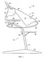
Figure 1 shows a first embodiment of the infant chair fastened to a base chair and adjusted to a sitting position for the infant. -
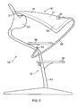
Figure 2 shows the first embodiment of the infant chair fastened to a base chair and adjusted to a lying position for the infant. -
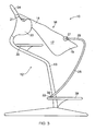
Figure 3 shows a second embodiment of the infant chair fastened to a base chair and adjusted to a sitting position for the infant. -
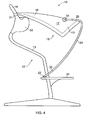
Figure 4 shows the second embodiment of the infant chair fastened to a base chair and adjusted to a lying position for the infant. -
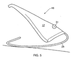
Figure 5 shows the infant chair as shown inFigures 1-4 , where the infant chair is used as a cradle alone on a flat surface. -
Figure 6 shows a third embodiment of the infant chair fastened to a base chair and adjusted to a sitting position for the infant. -
Figure 7 shows the third embodiment of the infant chair fastened to a base chair and adjusted to a lying position for the infant. -
Figure 8 shows a fourth embodiment of the infant chair fastened to a base chair and adjusted to a sitting position for the infant. -
Figure 9 shows the fourth embodiment of the infant chair fastened to a base chair and adjusted to a lying position for the infant. -
Figure 10 shows the infant chair as shown inFigures 6-9 , where the infant chair is used as a cradle alone on a flat surface. -
Figure 11 shows a fifth embodiment of the infant chair fastened to a base chair and adjusted to a sitting position for the infant. -
Figure 12 shows the fifth embodiment of the infant chair fastened to a base chair and adjusted to a lying position for the infant. - A number of different embodiments of the invention are described below. The different embodiments are, however, quite similar and the same reference numerals are therefore used to indicate the same or similar technical features of the different embodiments.
- In common for all the embodiments shown in
Figures 1-10 is that thechair assembly 10 comprises abase chair 12 and aninfant chair 16 that is fastened to the base chair. Thebase chair 12 comprises acolumn 13 that projects up from abase 14. Arranged on thecolumn 13 are afootrest part 39 and aseat part 36, both of which are arranged to be movable up and down along thecolumn 14. There are also provided locking means 37 for the seat part and 40 for the footrest part for locking the seat part and the footrest part in a desired position. - The base chair also comprises a
back part 33 which at an upper edge is configured with an upwardly projecting backpart 34 to which theinfant chair 16 can be fastened with the aid of anupper fastening device 21, for example a hood or a loop that is slipped down onto the upward projecting backpart 34. - The
infant chair 16 comprises achair part 17 having an upperchair part portion 18 and a lowerchair part portion 19. The infant chair further comprises a supportingelement 28, for example, a stay, having afirst end portion 29 that is pivotally fastened to the lowerchair part portion 19 of theinfant chair 16 with the aid of a chairpart fastening device 31 and pivotally fastened to afastening device 22 on thebase chair 12. By moving thefastening device 22 up or down along thecolumn 13 of thebase chair 12, the infant chair can be adjusted from a lying position to a sitting position for an infant that is placed in theinfant chair 16. - The difference between the different embodiments of the invention that are illustrated resides primarily in where the
lower fastening device 22 is arranged on thebase chair 12. - In the embodiment shown in
Figures 1-2 thefastening device 22 is arranged on theseat part 36 of thebase chair 12 or is configured as an integral part of theseat part 36. InFigure 1 the infant chair is shown in a sitting position, whilst by moving theseat part 36 downwards, theinfant chair 16 is moved into a lying position as shown inFigure 2 . - In the embodiment shown in
Figures 3-4 thefastening device 22 is arranged on thefootrest part 39 of thebase chair 12 or is configured as an integral part of thefootrest part 39. InFigure 3 the infant chair is shown in a sitting position, whilst by moving thefootrest part 39 downwards, theinfant chair 16 is moved to a lying position as shown inFigure 4 . - In
Figure 1-5 theinfant chair 16 is shown with supporting elements that are curved so as to form rockers. Theinfant chair 16 can thus be used as a cradle when it is not fastened to thebase chair 12 as shown inFigure 5 . - In the embodiment shown in
Figures 6-7 thefastening device 22 is arranged on thecolumn 13 of thebase chair 12. InFigure 6 the infant chair is shown in a sitting position, whilst by moving thefastening device 22 upwards along thecolumn 13 of thebase chair 12, theinfant chair 16 is moved to a lying position as shown inFigure 7 . - In the embodiment shown in
Figures 8-9 thefastening device 22 is arranged on theseat part 36 of thebase chair 12 or is configured as an integral part of theseat part 36. InFigure 8 the infant chair is shown in a sitting position, whilst by moving theseat part 36 downwards, theinfant chair 16 is moved to a lying position as shown inFigure 9 . - In
Figures 6-10 the supportingelement 28 is configured as a straight stay. There is otherwise no difference from the embodiment inFigures 1-4 .Figure 10 shows that the infant chair can be used as a sitting chair with the supportingelement 28 supporting the infant chair when it is placed on a flat underlying surface. -
Figures 11 and 12 show a slightly different embodiment of the infant chair as it is configured with arigid plate element 38 which rests against the front edge of theseat part 36. By moving theseat part 36 up or down along thecolumn 13 of thebase chair 12, the infant chair can be moved from a sitting position as shown inFigure 11 to a lying position as shown inFigure 12 .
Claims (15)
- An infant chair (16) that is adapted to be fastened to a base chair (12), which infant chair (16) comprises a chair part (17) having an upper chair part portion (18) and a lower chair part portion (19), the infant chair being configured such that the chair part (17) can be adjusted between a lying position and a sitting position for an infant, and wherein the infant chair (16) further comprises at least one supporting element (28) having a first end portion (29) and a second end portion, characterised in that
the first end portion (29) is pivotally fastened to the infant chair's chair part (19) and the second end portion comprises a lower fastening device (22) adapted for pivotal and detachable fastening to the base chair (12), and wherein the upper chair part portion (18) of the infant chair is arranged for pivotal and detachable fastening to the base chair (12). - An infant chair according to claim 1,
characterised in that the upper chair part portion (18) comprises at least one upper fastening device (21), and that the at least one upper fastening device is arranged to be fastened detachably to the base chair (12). - An infant chair according to claim 2,
characterised in that the at least one upper fastening device (21) is configured as a hood or a loop that can be slipped down onto the chair or a part of the chair. - An infant chair according to claim 2,
characterised in that the at least one upper fastening device (21) is configured as a clamp device that can be clamped to the chair or a part of the chair. - An infant chair according to one of claims 1-7,
characterised in that the at least one supporting element (28) is configured so as to be able to support the infant chair's chair part (17) thereby allowing the chair part to assume a sitting position on a flat underlying surface when the infant chair (16) is not fastened to the base chair (12). - A chair assembly (10) which, when assembled, comprises a base chair (12) and an infant chair (16) adapted to be fastened to the base chair (12), which infant chair comprises a chair part (17) having an upper chair part portion (18) and a lower chair part portion (19) and is configured such that the infant can sit or lie in the chair part (17) depending on the position of the chair part, characterised in that the infant chair (16) comprises at least one supporting element (28) having a first end portion (29) and a second end portion, which first end portion (29) is pivotally fastened to the chair part (17) of the infant chair and which second end portion is pivotally fastened to the base chair (12) by at least one lower fastening device (22); which upper chair part portion (18) is pivotally fastened to the base chair (12) by at least one upper fastening device (21); and wherein the at least one upper fastening device (21) and the at least one lower fastening device (22) are movably arranged in relation to one another such that the position of the infant chair's chair part (17) can be adjusted between a lying position and a sitting position.
- A chair assembly according to claim 6,
characterised in that the at least one lower fastening device (22) is fastened to the second end portion of the at least one supporting element (28) and that the at least one lower fastening device (22) is detachably fastened to the base chair (12). - A chair assembly according to claim 6,
characterised in that the at least one upper fastening device (21) is fastened to the upper chair part portion (18) of the infant chair and that the upper fastening device (21) is detachably fastened to the base chair (12). - A chair assembly according to one of claims 6-8,
characterised in that the at least one upper fastening device (21) is configured as a hood or a loop that can be slipped down onto the base chair (12) or a part of the base chair. - A chair assembly according to one of claims 6-9,
characterised in that the base chair (12) comprises a chair frame and that the at least one lower fastening device (22) and/or the at least one, upper fastening device (21) is slidably arranged in one or more grooves in the chair frame. - A chair assembly according to one of claims 6-10,
characterised in that the base chair (12) comprises a seat part (36) which can be moved up and down in relation to the rest of the chair, and that the at least one lower fastening device (22) either is configured as a part of the seat part (36) or is fastened to the seat part (36). - A chair assembly according to one of claims 6-11,
characterised in that the base chair (12) comprises a footrest part (39) that can be adjusted up and down in relation to the rest of the base chair (12), and that the at least one lower fastening device (22) is configured as a part of the footrest part (39) or is fastened to the footrest part (39). - A chair assembly according to one of claims 6-12,
characterised in that the chair part (36) of the infant chair can be adjusted steplessly to all positions between the lying position and the sitting position. - A chair assembly according to one of claims 6-13,
characterised in that the chair part (36) of the infant chair can be adjusted step by step to a number of positions between the lying position and the sitting position. - A chair assembly according to one of claims 6-14,
characterised in that the at least one supporting element (28) is configured so that it can support the chair part (36) of the infant chair such that the chair part can assume a sitting position on a flat underlying surface when the infant chair (16) is not fastened to a chair.
Applications Claiming Priority (2)
| Application Number | Priority Date | Filing Date | Title |
|---|---|---|---|
| NO20100920A NO20100920A1 (en) | 2010-06-24 | 2010-06-24 | High chair |
| PCT/EP2011/060604 WO2011161231A1 (en) | 2010-06-24 | 2011-06-24 | Infant chair and chair assembly comprising a base chair and an infant chair |
Publications (2)
| Publication Number | Publication Date |
|---|---|
| EP2584939A1 EP2584939A1 (en) | 2013-05-01 |
| EP2584939B1 true EP2584939B1 (en) | 2014-11-26 |
Family
ID=44627855
Family Applications (1)
| Application Number | Title | Priority Date | Filing Date |
|---|---|---|---|
| EP11729288.8A Active EP2584939B1 (en) | 2010-06-24 | 2011-06-24 | Infant chair and chair assembly comprising a base chair and an infant chair |
Country Status (4)
| Country | Link |
|---|---|
| EP (1) | EP2584939B1 (en) |
| DK (1) | DK2584939T3 (en) |
| NO (1) | NO20100920A1 (en) |
| WO (1) | WO2011161231A1 (en) |
Families Citing this family (1)
| Publication number | Priority date | Publication date | Assignee | Title |
|---|---|---|---|---|
| CN105266437A (en) * | 2014-06-30 | 2016-01-27 | 刘波 | Universal rocking chair using folding lifting principle |
Family Cites Families (9)
| Publication number | Priority date | Publication date | Assignee | Title |
|---|---|---|---|---|
| JPS5514284Y2 (en) * | 1977-08-09 | 1980-04-01 | ||
| US4553786A (en) * | 1983-08-10 | 1985-11-19 | William Lockett, III | Infant seating and lounge unit |
| FR2700456B1 (en) * | 1993-01-20 | 1995-03-17 | Thierry Germain | Multi-use baby carrier. |
| US5676386A (en) * | 1995-10-30 | 1997-10-14 | Huang; Li-Chu Chen | Stroller in combination with a safety seat assembly |
| GB2316978A (en) * | 1996-09-04 | 1998-03-11 | Cassidy Brothers Plc | Adjustable seat |
| US5951102A (en) * | 1996-12-27 | 1999-09-14 | Evenflo Company, Inc. | High chair |
| FR2763292B1 (en) * | 1997-05-16 | 1999-06-18 | Renault | SUPPORT DEVICE FOR A PASSENGER-CHILD SEAT |
| US6286844B1 (en) * | 1997-06-24 | 2001-09-11 | Cosco Management, Inc. | Stroller with removable seat |
| GB2380663A (en) * | 2001-10-10 | 2003-04-16 | Jenx Ltd | Premature baby support and positioning arrangement in which the support is hinged to the base |
-
2010
- 2010-06-24 NO NO20100920A patent/NO20100920A1/en not_active IP Right Cessation
-
2011
- 2011-06-24 DK DK11729288.8T patent/DK2584939T3/en active
- 2011-06-24 EP EP11729288.8A patent/EP2584939B1/en active Active
- 2011-06-24 WO PCT/EP2011/060604 patent/WO2011161231A1/en not_active Ceased
Also Published As
| Publication number | Publication date |
|---|---|
| WO2011161231A1 (en) | 2011-12-29 |
| DK2584939T3 (en) | 2015-02-23 |
| EP2584939A1 (en) | 2013-05-01 |
| NO331233B1 (en) | 2011-11-07 |
| NO20100920A1 (en) | 2011-11-07 |
Similar Documents
| Publication | Publication Date | Title |
|---|---|---|
| CN108720425B (en) | Multifunctional high chair | |
| JP5383103B2 (en) | Children's chair that has two functions | |
| US5810432A (en) | High chair system | |
| US6619734B2 (en) | Child support device with displaceable seat element | |
| US8162333B1 (en) | Combination child walker and high chair | |
| US9895005B2 (en) | Convertible child seat | |
| US7621592B1 (en) | Rocker and hook on high chair apparatus | |
| EP3053485B1 (en) | Adjustable booster seat | |
| CN119498651A (en) | Convertible infant chair assembly | |
| US9877598B2 (en) | Upright child high chair | |
| CA2124636A1 (en) | Adjustable stroller reclining mechanism | |
| KR101396857B1 (en) | Baby chairs for table use with amusement function | |
| US20150137565A1 (en) | Highchair | |
| US7210737B2 (en) | Feeding chair apparatus | |
| DK2584939T3 (en) | Chair and chair assembly comprising a base chair and a chair | |
| US20260000219A1 (en) | High Chair | |
| EP4518723B1 (en) | Sit-to-stand convertible highchair | |
| KR20130000534U (en) | Safe table-chair capable of controlling distance foran infant | |
| WO2025111320A1 (en) | Bassinet with mount | |
| JP3090970U (en) | Multifunctional chair with table | |
| EP2584938A1 (en) | An infant chair, a chair assembly comprising an infant chair and a base chair, and a method for mounting an infant chair on a base chair | |
| CN103153138B (en) | Bassinet and fixing device | |
| WO2008087456A1 (en) | A seat | |
| JP2005095611A (en) | Auxiliary chair | |
| HK1186079A (en) | Baby cradle and mounting device |
Legal Events
| Date | Code | Title | Description |
|---|---|---|---|
| PUAI | Public reference made under article 153(3) epc to a published international application that has entered the european phase |
Free format text: ORIGINAL CODE: 0009012 |
|
| 17P | Request for examination filed |
Effective date: 20130124 |
|
| AK | Designated contracting states |
Kind code of ref document: A1 Designated state(s): AL AT BE BG CH CY CZ DE DK EE ES FI FR GB GR HR HU IE IS IT LI LT LU LV MC MK MT NL NO PL PT RO RS SE SI SK SM TR |
|
| DAX | Request for extension of the european patent (deleted) | ||
| GRAP | Despatch of communication of intention to grant a patent |
Free format text: ORIGINAL CODE: EPIDOSNIGR1 |
|
| INTG | Intention to grant announced |
Effective date: 20140619 |
|
| GRAS | Grant fee paid |
Free format text: ORIGINAL CODE: EPIDOSNIGR3 |
|
| GRAA | (expected) grant |
Free format text: ORIGINAL CODE: 0009210 |
|
| AK | Designated contracting states |
Kind code of ref document: B1 Designated state(s): AL AT BE BG CH CY CZ DE DK EE ES FI FR GB GR HR HU IE IS IT LI LT LU LV MC MK MT NL NO PL PT RO RS SE SI SK SM TR |
|
| REG | Reference to a national code |
Ref country code: GB Ref legal event code: FG4D |
|
| REG | Reference to a national code |
Ref country code: CH Ref legal event code: EP |
|
| REG | Reference to a national code |
Ref country code: AT Ref legal event code: REF Ref document number: 697687 Country of ref document: AT Kind code of ref document: T Effective date: 20141215 |
|
| REG | Reference to a national code |
Ref country code: IE Ref legal event code: FG4D |
|
| REG | Reference to a national code |
Ref country code: DE Ref legal event code: R096 Ref document number: 602011011731 Country of ref document: DE Effective date: 20141231 |
|
| REG | Reference to a national code |
Ref country code: DK Ref legal event code: T3 Effective date: 20150219 |
|
| REG | Reference to a national code |
Ref country code: NL Ref legal event code: T3 |
|
| REG | Reference to a national code |
Ref country code: AT Ref legal event code: MK05 Ref document number: 697687 Country of ref document: AT Kind code of ref document: T Effective date: 20141126 |
|
| REG | Reference to a national code |
Ref country code: LT Ref legal event code: MG4D |
|
| PG25 | Lapsed in a contracting state [announced via postgrant information from national office to epo] |
Ref country code: LT Free format text: LAPSE BECAUSE OF FAILURE TO SUBMIT A TRANSLATION OF THE DESCRIPTION OR TO PAY THE FEE WITHIN THE PRESCRIBED TIME-LIMIT Effective date: 20141126 Ref country code: PT Free format text: LAPSE BECAUSE OF FAILURE TO SUBMIT A TRANSLATION OF THE DESCRIPTION OR TO PAY THE FEE WITHIN THE PRESCRIBED TIME-LIMIT Effective date: 20150326 Ref country code: FI Free format text: LAPSE BECAUSE OF FAILURE TO SUBMIT A TRANSLATION OF THE DESCRIPTION OR TO PAY THE FEE WITHIN THE PRESCRIBED TIME-LIMIT Effective date: 20141126 Ref country code: IS Free format text: LAPSE BECAUSE OF FAILURE TO SUBMIT A TRANSLATION OF THE DESCRIPTION OR TO PAY THE FEE WITHIN THE PRESCRIBED TIME-LIMIT Effective date: 20150326 Ref country code: ES Free format text: LAPSE BECAUSE OF FAILURE TO SUBMIT A TRANSLATION OF THE DESCRIPTION OR TO PAY THE FEE WITHIN THE PRESCRIBED TIME-LIMIT Effective date: 20141126 Ref country code: NO Free format text: LAPSE BECAUSE OF FAILURE TO SUBMIT A TRANSLATION OF THE DESCRIPTION OR TO PAY THE FEE WITHIN THE PRESCRIBED TIME-LIMIT Effective date: 20150226 |
|
| PG25 | Lapsed in a contracting state [announced via postgrant information from national office to epo] |
Ref country code: AT Free format text: LAPSE BECAUSE OF FAILURE TO SUBMIT A TRANSLATION OF THE DESCRIPTION OR TO PAY THE FEE WITHIN THE PRESCRIBED TIME-LIMIT Effective date: 20141126 Ref country code: RS Free format text: LAPSE BECAUSE OF FAILURE TO SUBMIT A TRANSLATION OF THE DESCRIPTION OR TO PAY THE FEE WITHIN THE PRESCRIBED TIME-LIMIT Effective date: 20141126 Ref country code: SE Free format text: LAPSE BECAUSE OF FAILURE TO SUBMIT A TRANSLATION OF THE DESCRIPTION OR TO PAY THE FEE WITHIN THE PRESCRIBED TIME-LIMIT Effective date: 20141126 Ref country code: HR Free format text: LAPSE BECAUSE OF FAILURE TO SUBMIT A TRANSLATION OF THE DESCRIPTION OR TO PAY THE FEE WITHIN THE PRESCRIBED TIME-LIMIT Effective date: 20141126 Ref country code: GR Free format text: LAPSE BECAUSE OF FAILURE TO SUBMIT A TRANSLATION OF THE DESCRIPTION OR TO PAY THE FEE WITHIN THE PRESCRIBED TIME-LIMIT Effective date: 20150227 Ref country code: CY Free format text: LAPSE BECAUSE OF FAILURE TO SUBMIT A TRANSLATION OF THE DESCRIPTION OR TO PAY THE FEE WITHIN THE PRESCRIBED TIME-LIMIT Effective date: 20141126 Ref country code: LV Free format text: LAPSE BECAUSE OF FAILURE TO SUBMIT A TRANSLATION OF THE DESCRIPTION OR TO PAY THE FEE WITHIN THE PRESCRIBED TIME-LIMIT Effective date: 20141126 |
|
| PG25 | Lapsed in a contracting state [announced via postgrant information from national office to epo] |
Ref country code: SK Free format text: LAPSE BECAUSE OF FAILURE TO SUBMIT A TRANSLATION OF THE DESCRIPTION OR TO PAY THE FEE WITHIN THE PRESCRIBED TIME-LIMIT Effective date: 20141126 Ref country code: RO Free format text: LAPSE BECAUSE OF FAILURE TO SUBMIT A TRANSLATION OF THE DESCRIPTION OR TO PAY THE FEE WITHIN THE PRESCRIBED TIME-LIMIT Effective date: 20141126 Ref country code: CZ Free format text: LAPSE BECAUSE OF FAILURE TO SUBMIT A TRANSLATION OF THE DESCRIPTION OR TO PAY THE FEE WITHIN THE PRESCRIBED TIME-LIMIT Effective date: 20141126 Ref country code: EE Free format text: LAPSE BECAUSE OF FAILURE TO SUBMIT A TRANSLATION OF THE DESCRIPTION OR TO PAY THE FEE WITHIN THE PRESCRIBED TIME-LIMIT Effective date: 20141126 |
|
| REG | Reference to a national code |
Ref country code: DE Ref legal event code: R097 Ref document number: 602011011731 Country of ref document: DE |
|
| PG25 | Lapsed in a contracting state [announced via postgrant information from national office to epo] |
Ref country code: PL Free format text: LAPSE BECAUSE OF FAILURE TO SUBMIT A TRANSLATION OF THE DESCRIPTION OR TO PAY THE FEE WITHIN THE PRESCRIBED TIME-LIMIT Effective date: 20141126 |
|
| PLBE | No opposition filed within time limit |
Free format text: ORIGINAL CODE: 0009261 |
|
| STAA | Information on the status of an ep patent application or granted ep patent |
Free format text: STATUS: NO OPPOSITION FILED WITHIN TIME LIMIT |
|
| 26N | No opposition filed |
Effective date: 20150827 |
|
| PG25 | Lapsed in a contracting state [announced via postgrant information from national office to epo] |
Ref country code: IT Free format text: LAPSE BECAUSE OF FAILURE TO SUBMIT A TRANSLATION OF THE DESCRIPTION OR TO PAY THE FEE WITHIN THE PRESCRIBED TIME-LIMIT Effective date: 20141126 |
|
| PG25 | Lapsed in a contracting state [announced via postgrant information from national office to epo] |
Ref country code: MC Free format text: LAPSE BECAUSE OF FAILURE TO SUBMIT A TRANSLATION OF THE DESCRIPTION OR TO PAY THE FEE WITHIN THE PRESCRIBED TIME-LIMIT Effective date: 20141126 |
|
| REG | Reference to a national code |
Ref country code: CH Ref legal event code: PL |
|
| PG25 | Lapsed in a contracting state [announced via postgrant information from national office to epo] |
Ref country code: SI Free format text: LAPSE BECAUSE OF FAILURE TO SUBMIT A TRANSLATION OF THE DESCRIPTION OR TO PAY THE FEE WITHIN THE PRESCRIBED TIME-LIMIT Effective date: 20141126 Ref country code: LU Free format text: LAPSE BECAUSE OF FAILURE TO SUBMIT A TRANSLATION OF THE DESCRIPTION OR TO PAY THE FEE WITHIN THE PRESCRIBED TIME-LIMIT Effective date: 20150624 |
|
| REG | Reference to a national code |
Ref country code: IE Ref legal event code: MM4A |
|
| PG25 | Lapsed in a contracting state [announced via postgrant information from national office to epo] |
Ref country code: LI Free format text: LAPSE BECAUSE OF NON-PAYMENT OF DUE FEES Effective date: 20150630 Ref country code: CH Free format text: LAPSE BECAUSE OF NON-PAYMENT OF DUE FEES Effective date: 20150630 Ref country code: IE Free format text: LAPSE BECAUSE OF NON-PAYMENT OF DUE FEES Effective date: 20150624 |
|
| REG | Reference to a national code |
Ref country code: FR Ref legal event code: PLFP Year of fee payment: 6 |
|
| PG25 | Lapsed in a contracting state [announced via postgrant information from national office to epo] |
Ref country code: MT Free format text: LAPSE BECAUSE OF FAILURE TO SUBMIT A TRANSLATION OF THE DESCRIPTION OR TO PAY THE FEE WITHIN THE PRESCRIBED TIME-LIMIT Effective date: 20141126 |
|
| PG25 | Lapsed in a contracting state [announced via postgrant information from national office to epo] |
Ref country code: BG Free format text: LAPSE BECAUSE OF FAILURE TO SUBMIT A TRANSLATION OF THE DESCRIPTION OR TO PAY THE FEE WITHIN THE PRESCRIBED TIME-LIMIT Effective date: 20141126 Ref country code: SM Free format text: LAPSE BECAUSE OF FAILURE TO SUBMIT A TRANSLATION OF THE DESCRIPTION OR TO PAY THE FEE WITHIN THE PRESCRIBED TIME-LIMIT Effective date: 20141126 Ref country code: HU Free format text: LAPSE BECAUSE OF FAILURE TO SUBMIT A TRANSLATION OF THE DESCRIPTION OR TO PAY THE FEE WITHIN THE PRESCRIBED TIME-LIMIT; INVALID AB INITIO Effective date: 20110624 |
|
| REG | Reference to a national code |
Ref country code: FR Ref legal event code: PLFP Year of fee payment: 7 |
|
| PG25 | Lapsed in a contracting state [announced via postgrant information from national office to epo] |
Ref country code: TR Free format text: LAPSE BECAUSE OF FAILURE TO SUBMIT A TRANSLATION OF THE DESCRIPTION OR TO PAY THE FEE WITHIN THE PRESCRIBED TIME-LIMIT Effective date: 20141126 |
|
| PG25 | Lapsed in a contracting state [announced via postgrant information from national office to epo] |
Ref country code: BE Free format text: LAPSE BECAUSE OF FAILURE TO SUBMIT A TRANSLATION OF THE DESCRIPTION OR TO PAY THE FEE WITHIN THE PRESCRIBED TIME-LIMIT Effective date: 20141126 |
|
| REG | Reference to a national code |
Ref country code: FR Ref legal event code: PLFP Year of fee payment: 8 |
|
| PG25 | Lapsed in a contracting state [announced via postgrant information from national office to epo] |
Ref country code: MK Free format text: LAPSE BECAUSE OF FAILURE TO SUBMIT A TRANSLATION OF THE DESCRIPTION OR TO PAY THE FEE WITHIN THE PRESCRIBED TIME-LIMIT Effective date: 20141126 |
|
| PG25 | Lapsed in a contracting state [announced via postgrant information from national office to epo] |
Ref country code: AL Free format text: LAPSE BECAUSE OF FAILURE TO SUBMIT A TRANSLATION OF THE DESCRIPTION OR TO PAY THE FEE WITHIN THE PRESCRIBED TIME-LIMIT Effective date: 20141126 |
|
| PGFP | Annual fee paid to national office [announced via postgrant information from national office to epo] |
Ref country code: DE Payment date: 20250618 Year of fee payment: 15 |
|
| PGFP | Annual fee paid to national office [announced via postgrant information from national office to epo] |
Ref country code: GB Payment date: 20250618 Year of fee payment: 15 |
|
| PGFP | Annual fee paid to national office [announced via postgrant information from national office to epo] |
Ref country code: NL Payment date: 20250616 Year of fee payment: 15 |
|
| PGFP | Annual fee paid to national office [announced via postgrant information from national office to epo] |
Ref country code: FR Payment date: 20250617 Year of fee payment: 15 |
|
| PGFP | Annual fee paid to national office [announced via postgrant information from national office to epo] |
Ref country code: DK Payment date: 20260317 Year of fee payment: 16 |