EP2584854B1 - Channel arrangement method and wireless communication base station device - Google Patents
Channel arrangement method and wireless communication base station device Download PDFInfo
- Publication number
- EP2584854B1 EP2584854B1 EP13151604.9A EP13151604A EP2584854B1 EP 2584854 B1 EP2584854 B1 EP 2584854B1 EP 13151604 A EP13151604 A EP 13151604A EP 2584854 B1 EP2584854 B1 EP 2584854B1
- Authority
- EP
- European Patent Office
- Prior art keywords
- prbs
- rbs
- allocated
- dch
- mapped
- Prior art date
- Legal status (The legal status is an assumption and is not a legal conclusion. Google has not performed a legal analysis and makes no representation as to the accuracy of the status listed.)
- Active
Links
- 238000000034 method Methods 0.000 title claims description 134
- 238000004891 communication Methods 0.000 title description 24
- 238000013507 mapping Methods 0.000 claims description 157
- 101150071746 Pbsn gene Proteins 0.000 claims description 33
- 230000001419 dependent effect Effects 0.000 claims description 2
- 230000005540 biological transmission Effects 0.000 description 55
- 230000000694 effects Effects 0.000 description 22
- 230000006866 deterioration Effects 0.000 description 17
- 101150077508 RBG1 gene Proteins 0.000 description 15
- 230000003044 adaptive effect Effects 0.000 description 15
- 239000000284 extract Substances 0.000 description 15
- 101150028167 RBG2 gene Proteins 0.000 description 11
- 238000006243 chemical reaction Methods 0.000 description 8
- 101100411816 Arabidopsis thaliana RBG3 gene Proteins 0.000 description 7
- 238000005516 engineering process Methods 0.000 description 4
- 230000010354 integration Effects 0.000 description 3
- 230000011664 signaling Effects 0.000 description 3
- 230000003321 amplification Effects 0.000 description 2
- 238000010586 diagram Methods 0.000 description 2
- 238000000605 extraction Methods 0.000 description 2
- 238000010295 mobile communication Methods 0.000 description 2
- 238000003199 nucleic acid amplification method Methods 0.000 description 2
- 101100411820 Arabidopsis thaliana RBG7 gene Proteins 0.000 description 1
- 125000004122 cyclic group Chemical group 0.000 description 1
- 230000002542 deteriorative effect Effects 0.000 description 1
- 238000004519 manufacturing process Methods 0.000 description 1
- 239000004065 semiconductor Substances 0.000 description 1
Images


Classifications
-
- H—ELECTRICITY
- H04—ELECTRIC COMMUNICATION TECHNIQUE
- H04W—WIRELESS COMMUNICATION NETWORKS
- H04W72/00—Local resource management
- H04W72/04—Wireless resource allocation
- H04W72/044—Wireless resource allocation based on the type of the allocated resource
- H04W72/0453—Resources in frequency domain, e.g. a carrier in FDMA
-
- H—ELECTRICITY
- H04—ELECTRIC COMMUNICATION TECHNIQUE
- H04W—WIRELESS COMMUNICATION NETWORKS
- H04W72/00—Local resource management
- H04W72/04—Wireless resource allocation
-
- H—ELECTRICITY
- H04—ELECTRIC COMMUNICATION TECHNIQUE
- H04J—MULTIPLEX COMMUNICATION
- H04J11/00—Orthogonal multiplex systems, e.g. using WALSH codes
-
- H—ELECTRICITY
- H04—ELECTRIC COMMUNICATION TECHNIQUE
- H04L—TRANSMISSION OF DIGITAL INFORMATION, e.g. TELEGRAPHIC COMMUNICATION
- H04L5/00—Arrangements affording multiple use of the transmission path
- H04L5/0001—Arrangements for dividing the transmission path
- H04L5/0003—Two-dimensional division
- H04L5/0005—Time-frequency
- H04L5/0007—Time-frequency the frequencies being orthogonal, e.g. OFDM(A), DMT
- H04L5/001—Time-frequency the frequencies being orthogonal, e.g. OFDM(A), DMT the frequencies being arranged in component carriers
-
- H—ELECTRICITY
- H04—ELECTRIC COMMUNICATION TECHNIQUE
- H04L—TRANSMISSION OF DIGITAL INFORMATION, e.g. TELEGRAPHIC COMMUNICATION
- H04L5/00—Arrangements affording multiple use of the transmission path
- H04L5/003—Arrangements for allocating sub-channels of the transmission path
- H04L5/0042—Arrangements for allocating sub-channels of the transmission path intra-user or intra-terminal allocation
-
- H—ELECTRICITY
- H04—ELECTRIC COMMUNICATION TECHNIQUE
- H04L—TRANSMISSION OF DIGITAL INFORMATION, e.g. TELEGRAPHIC COMMUNICATION
- H04L5/00—Arrangements affording multiple use of the transmission path
- H04L5/003—Arrangements for allocating sub-channels of the transmission path
- H04L5/0044—Arrangements for allocating sub-channels of the transmission path allocation of payload
-
- H—ELECTRICITY
- H04—ELECTRIC COMMUNICATION TECHNIQUE
- H04L—TRANSMISSION OF DIGITAL INFORMATION, e.g. TELEGRAPHIC COMMUNICATION
- H04L5/00—Arrangements affording multiple use of the transmission path
- H04L5/003—Arrangements for allocating sub-channels of the transmission path
- H04L5/0053—Allocation of signaling, i.e. of overhead other than pilot signals
-
- H—ELECTRICITY
- H04—ELECTRIC COMMUNICATION TECHNIQUE
- H04W—WIRELESS COMMUNICATION NETWORKS
- H04W72/00—Local resource management
-
- H—ELECTRICITY
- H04—ELECTRIC COMMUNICATION TECHNIQUE
- H04W—WIRELESS COMMUNICATION NETWORKS
- H04W72/00—Local resource management
- H04W72/04—Wireless resource allocation
- H04W72/044—Wireless resource allocation based on the type of the allocated resource
-
- H—ELECTRICITY
- H04—ELECTRIC COMMUNICATION TECHNIQUE
- H04W—WIRELESS COMMUNICATION NETWORKS
- H04W72/00—Local resource management
- H04W72/20—Control channels or signalling for resource management
- H04W72/23—Control channels or signalling for resource management in the downlink direction of a wireless link, i.e. towards a terminal
Definitions
- the present invention relates to a channel mapping method and a radio communication base station apparatus in multicarrier communication.
- OFDM Orthogonal Frequency Division Multiplexing
- a radio communication base station apparatus (hereinafter simply referred to as "base station") adaptively allocates subcarriers to each mobile station based on received quality per frequency band at each mobile station, and thereby obtain maximum multiuser diversity effect and carry out communication very efficiently.
- Such frequency scheduling transmission is a scheme suitable for mainly data communication or high-speed data communication when a mobile station is moving at a low speed.
- frequency scheduling transmission requires feedback of received quality information from each mobile station, frequency scheduling transmission is unsuitable for data communication when the mobile station is moving at a high speed.
- frequency scheduling is normally performed per resource block (RB) formed into a block by grouping several neighboring subcarriers into a transmission time unit called “subframe.”
- the channel for carrying out such frequency scheduling transmission is called “localized channel” (hereinafter referred to as "Lch").
- frequency diversity transmission data for each mobile station is distributed across and allocated to subcarriers in the entire band, and high frequency diversity effect can therefore be obtained. Furthermore, frequency diversity transmission does not require received quality information from the mobile station, and therefore this is an effective scheme in the situation as described above in which it is difficult to apply frequency scheduling transmission. On the other hand, since frequency diversity transmission is carried out irrespective of the received quality at each mobile station, no multiuser diversity effect as in the case of frequency scheduling transmission is obtained.
- the channel for carrying out such frequency diversity transmission is called “Distributed Channel (hereinafter referred to as "Dch").
- frequency scheduling transmission through Lch and frequency diversity transmission through Dch may be carried out at the same time. That is, RBs used for Lch and RBs used for Dch on a plurality of subcarriers of one OFDM symbol may be frequency-domain-multiplexed.
- each RB and Lch are associated with each other and each RB and Dch are associated with each other in advance, and it is controlled in subframe units which RB should be used as Lch or Dch.
- Non-Patent Document 1 studies are being conducted to divide RBs to use for Dch into a plurality of subblocks and configure one Dch by a combination of different RB subblocks (e.g., see Non-Patent Document 1). To be more specific, when an RB is divided into two subblocks, one Dch is mapped to two divided subblocks.
- WO 2007/094628 A1 relates to an allocation of radio resources using a localized transmission scheme and a distributed transmission scheme in combination in an orthogonal frequency division multiple access system.
- the scheme includes changing the positions of the PRBs to which the distributed VRBs are mapped for each cell.
- a first cell is assigned PRBs (0, 4, 8) and a second cell is assigned PRBs (1, 5, 9) for distributed transmission.
- a distributed transmission scheme for a third cell includes this cell to be assigned with PRBs (0, 2, 6) for distributed transmission.
- WO 2008/020623 A1 relates to an allocation of distributed and localized resource blocks.
- the interval between RBs to which one Dch is mapped (hereinafter referred to as "RB interval") is determined in advance.
- RB interval the interval between RBs to which one Dch is mapped
- the RB interval is "floor" (the number of all RBs/2).
- the operator floor(x) denotes the maximum integer not exceeding x.
- Dchs can be mapped to RBs at equal intervals.
- the base station allocates Dchs to resource blocks first and then allocates Lchs to resource blocks to prevent collision between Dch allocation and Lch allocation.
- the base station allocates a plurality of Dchs to one mobile station
- frequency diversity effect does not substantially change no matter which Dch is allocated to resource blocks, and therefore a plurality of Dchs with continuous channel numbers are allocated.
- the mobile station can judge the Dchs allocated to that mobile station. Therefore, it is possible to reduce control information for indicating the Dch allocation result.
- the base station when the base station allocates Lchs, the base station reports the RBs to which Lchs have been allocated to the mobile station through a bitmap-type allocation report to allocate Lchs to RBs of high quality.
- the base station groups a plurality of RBs into a plurality of RB groups, allocates Lchs in RB group units, and thereby reduce control information for indicating the Lch allocation result. For example, in a system with 14 RBs, mapping per RB requires 14 bits of control information, but allocation in RB group units formed with 2 RBs requires only 7 bits of control information.
- Dchs are allocated to RBs #1, #2, #8 and #9 and Lchs are allocated to the rest of the RBs.
- Lchs are allocated to units of one RB group, each including two RBs, Lchs are allocated to the RB groups of (RBs #3 and #4), (RBs #5 and #6), (RBs #11 and #12) and (RBs #13 and #14).
- RB #7 and RB #10 since the other RBs constituting their respective RB groups are allocated to Dchs, Lchs cannot be allocated to RB #7 and RB #10.
- a related channel mapping method useful for understanding the invention divides a plurality of subcarriers comprised of a multicarrier signal into a plurality of resource blocks and groups the plurality of resource blocks into a plurality of groups so that one distributed channel is mapped at intervals of an integer multiple of the number of resource blocks constituting one group in the plurality of resource blocks.
- the present invention can prevent deterioration of the utilization efficiency of communication resources when carrying out frequency scheduling transmission and frequency diversity transmission at the same time in multicarrier communication.
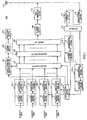
- FIG.1 illustrates a configuration of base station 100 according to the present embodiment.
- Base station 100 divides a plurality of subcarriers comprised of an OFDM symbol, which is a multicarrier signal, into a plurality of RBs and uses Dch and Lch for each RB of the plurality of RBs. Furthermore, one of Dch and Lch is allocated to one mobile station in the same subframe.
- Base station 100 is provided with n (n is the number of mobile stations (MSs) with which base station 100 can communicate) encoding/modulation sections 101-1 to 101-n each comprising encoding section 11 and modulation section 12 for Dch data, n encoding/modulation sections 102-1 to 102-n each comprising encoding section 21 and modulation section 22 for Lch data and n demodulation/decoding sections 115-1 to 115-n each comprising demodulation section 31 and decoding section 32.
- MSs mobile stations
- encoding section 11 performs encoding processing using a turbo code or the like on Dch data #1 to #n for each of mobile stations #1 to #n and modulation section 12 performs modulation processing on the encoded Dch data to thereby generate a Dch data symbol.
- encoding section 21 performs encoding processing using a turbo code or the like on Lch data #1 to #n for each of mobile stations #1 to #n and modulation section 22 performs modulation processing on the encoded Lch data to thereby generate an Lch data symbol.
- the coding rate and modulation scheme in this case follows MCS (Modulation and Coding Scheme: MCS) information inputted from adaptive control section 116.
- Allocation section 103 allocates the Dch data symbol and Lch data symbol to each subcarrier comprised of an OFDM symbol according to the control from adaptive control section 116 and outputs the OFDM symbol to multiplexing section 104. In this case, allocation section 103 collectively allocates the Dch data symbols and Lch data symbols for each RB. Furthermore, when allocating the Lch data symbols, allocation section 103 groups the plurality of RBs into a plurality of groups and allocates Lchs in RB group units. Furthermore, when using a plurality of Dchs for the Dch data symbol of one mobile station, allocation section 103 uses Dchs with continuous channel numbers.
- allocation section 103 allocates the Dch data symbol to a plurality of RBs to which one Dch is mapped at intervals of an integer multiple of the number of RBs constituting one RB group.
- the mapping positions of Dch and Lch are associated with each other in advance. That is, allocation section 103 stores a mapping pattern, which is the association between Dchs and Lchs, and RBs in advance and allocates the Dch data symbol and Lch data symbol to each RB according to the mapping pattern. Details of the Dch mapping method according to the present embodiment will be described later.
- allocation section 103 outputs allocation information of the Dch data symbol (information indicating which mobile station's Dch data symbol is allocated to which RBs) and allocation information of the Lch data symbol (information indicating which RBs are allocated to the Lch data symbol of which mobile station) to control information generation section 105.
- the allocation information of the Dch data symbol only includes the first channel number and the last channel number of the continuous channel numbers.
- Control information generation section 105 generates control information including the allocation information of the Dch data symbol, allocation information of the Lch data symbol and MCS information inputted from adaptive control section 116 and outputs the control information to encoding section 106.
- Encoding section 106 performs encoding processing on the control information and modulation section 107 performs modulation processing on the encoded control information and outputs the control information to multiplexing section 104.
- Multiplexing section 104 multiplexes each data symbol inputted from allocation section 103 with control information and outputs the multiplexing result to IFFT (Inverse Fast Fourier Transform) section 108. Multiplexing of control information is performed, for example, every subframe. According to the present embodiment, multiplexing of control information may be one of time domain multiplexing and frequency domain multiplexing.
- IFFT section 108 performs IFFT on a plurality of subcarriers comprised of a plurality of RBs to which control information and data symbol are allocated, to generate an OFDM symbol, which is a multicarrier signal.
- CP (Cyclic Prefix) adding section 109 adds the same signal as the last portion of the OFDM symbol to the head of the OFDM symbol as a CP.
- Radio transmitting section 110 performs transmission processing such as D/A conversion, amplification and up-conversion on the OFDM symbol with a CP and transmits the OFDM symbol from antenna 111 to each mobile station.
- radio receiving section 112 receives n OFDM symbols at the same time transmitted from maximum n mobile stations via antenna 111 and performs reception processing such as down-conversion, A/D conversion on these OFDM symbols.
- CP removing section 113 removes the CP from the OFDM symbol after the reception processing.
- FFT (Fast Fourier Transform) section 114 performs FFT on the OFDM symbol without a CP to obtain a signal for each mobile station multiplexed in the frequency domain.
- the respective mobile stations transmit signals using subcarriers different from each other or RBs different from each other and a signal for each mobile station includes received quality information for each RB reported from each mobile station.
- Each mobile station can measure the received quality of each RB using received SNR, received SIR, received SINR, received CINR, received power, interference power, bit error rate, throughput and MCS or the like that can achieve a certain error rate.
- the received quality information may be expressed as "CQI" (Channel Quality Indicator), "CSI” (Channel State Information) and so on.
- demodulation section 31 performs demodulation processing on the signal after the FFT and decoding section 32 performs decoding processing on the demodulated signal.
- the received data is thereby obtained.
- the received quality information is inputted to adaptive control section 116.
- Adaptive control section 116 performs adaptive control over Lch data based on the received quality information for each RB reported from each mobile station. That is, for encoding/modulation sections 102-1 to 102-n, adaptive control section 116 selects MCS whereby a required error rate can be satisfied for each RB group based on the received quality information for each RB and outputs the MCS information, and for allocation section 103, adaptive control section 116 performs frequency scheduling to determine to which RB group Lch data #1 to #n should be allocated respectively using a scheduling algorithm such as a Max SIR method or Proportional Fairness method. Furthermore, adaptive control section 116 outputs MCS information for each RB group to control information generation section 105.
- Mobile station 200 receives a multicarrier signal, which is an OFDM symbol comprised of a plurality of subcarriers divided into a plurality of RBs, from base station 100 ( FIG.1 ). Furthermore, Dch and Lch are used for each RB in a plurality of RBs. Furthermore, one of Dch and Lch is allocated to mobile station 200 in the same subframe.
- a multicarrier signal which is an OFDM symbol comprised of a plurality of subcarriers divided into a plurality of RBs, from base station 100 ( FIG.1 ).
- Dch and Lch are used for each RB in a plurality of RBs. Furthermore, one of Dch and Lch is allocated to mobile station 200 in the same subframe.
- radio receiving section 202 receives the OFDM symbol transmitted from base station 100 via antenna 201 and performs reception processing such as down-conversion or A/D conversion on the OFDM symbol.
- CP removing section 203 removes CP from the OFDM symbol after the reception processing.
- FFT section 204 performs FFT on the OFDM symbol without a CP to obtain a received signal in which control information and data symbols are multiplexed.
- Demultiplexing section 205 demultiplexes the received signal after the FFT into a control signal and data symbol. Demultiplexing section 205 then outputs the control signal to demodulation/decoding section 206 and outputs the data symbol to demapping section 207.
- demodulation/decoding section 206 demodulation section 41 performs demodulation processing on the control signal and decoding section 42 performs decoding processing on the demodulated signal.
- the control information includes Dch data symbol allocation information, Lch data symbol allocation information and MCS information.
- Demodulation/decoding section 206 then outputs the Dch data symbol allocation information and the Lch data symbol allocation information out of the control information to demapping section 207.
- Demapping section 207 extracts the data symbol allocated to that mobile station from among the plurality of RBs to which data symbols inputted from demultiplexing section 205 are allocated based on the allocation information inputted from demodulation/decoding section 206.
- mapping positions of Dchs and Lchs are associated with each other in advance as with base station 100 ( FIG.1 ). That is, demapping section 207 stores the same mapping pattern as that of allocation section 103 of base station 100 and extracts Dch data symbols and Lch data symbols from a plurality of RBs according to the mapping pattern.
- demapping section 207 extracts Lchs in RB group units in which a plurality of RBs are grouped into a plurality of groups. Furthermore, as described above, when a plurality of Dchs are used for a Dch data symbol of one mobile station, allocation section 103 of base station 100 ( FIG.1 ) uses Dchs with continuous channel numbers. Furthermore, the allocation information included in the control information from base station 100 indicates only the first channel number and the last channel number among the continuous channel numbers of Dchs used for the Dch data symbol. Thus, demapping section 207 specifies Dchs used for the Dch data symbol allocated to that mobile station based on the first channel number and the last channel number indicated in the allocation information.
- demapping section 207 identifies a plurality of continuous Dchs from the first channel number indicated in the allocation information to the last channel number indicated in the allocation information as Dchs used for the Dch data symbol allocated to that mobile station. Demapping section 207 then extracts the RB associated with the specified channel number of the identified Dch and outputs the data symbol allocated to the extracted RB to demodulation/decoding section 208.
- demodulation section 51 performs demodulation processing on the data symbol inputted from demapping section 207 and decoding section 52 performs decoding processing on the demodulated signal. The received data is thereby obtained.
- encoding section 61 performs encoding processing using a turbo code or the like on the transmission data and modulation section 62 performs modulation processing on the encoded transmission data to generate a data symbol.
- mobile station 200 transmits transmission data using subcarriers or RBs different from those of other mobile stations and the transmission data includes receiving quality information for each RB.
- IFFT section 210 performs IFFT on a plurality of subcarriers comprised of a plurality of RBs to which data symbols inputted from encoding/modulation section 209 are allocated, to generate an OFDM symbol, which is a multicarrier signal.
- CP adding section 211 adds the same signal as the last portion of the OFDM symbol to the head of the OFDM symbol as a CP.
- Radio transmitting section 212 performs transmission processing such as D/A conversion, amplification and up-conversion on the OFDM symbol with a CP and transmits the OFDM symbol to base station 100 ( FIG.1 ) from antenna 201.
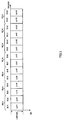
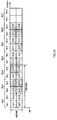
- Lch #1 and Lch #2 mapped to RB #1 and RB #2 constituting RBG1 are always allocated at the same time and Lch #3 and Lch #4 mapped to RB #3 and RB #4 constituting RBG2 are always allocated at the same time.
- Lchs #5 to #14 constituting RBGs #3 to #7 respectively.
- the Lch configuration in each RB shown in FIG.3 and the Dch configuration in each RB shown below are associated with each other in advance in allocation section 103.
- each RB used for Lch includes an Lch data symbol for only one mobile station. That is, one Lch corresponding to one mobile station is formed with one RB. Therefore, as shown in FIG.3 , Lchs #1 to #12 are mapped to RBs #1 to #12 respectively. That is, the allocation unit of each Lch is "1 RB ⁇ 1 subframe.”
- RB used for Dch includes a plurality of Dch data symbols.
- each RB used for Dch is temporally divided into two subblocks and different Dchs are mapped to each subblock. That is, a plurality of different Dchs are time-domain-multiplexed in 1 RB.
- one Dch is formed with two different RB subblocks. That is, the allocation unit of each Dch is "(1 RB ⁇ 1/2 subframe) ⁇ 2" and is the same as the allocation unit of each Lch.
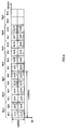
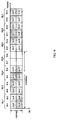
- one Dch is mapped at intervals of an integer multiple of the RB group size for a plurality of RBs.
- Dchs #1 and #7 are mapped to RB #1 (RB #7)
- Dchs #2 and #8 are mapped to RB #2 (RB #8)
- Dchs #3 and #9 are mapped to RB #3 (RB #9)
- Dchs #4 and #10 are mapped to RB #4 (RB #10)
- Dchs #5 and #11 are mapped to RB #5 (RB #11)
- Dchs #6 and #12 are mapped to RB #6 (RB #12). That is, according to the present mapping method, the maximum number of Dchs that allocation section 103 can allocate to RBs is 12.
- FIG.5 illustrates a allocation example in allocation section 103 ( FIG.1 ) of base station 100 when four Dchs are allocated to a Dch data symbol of one mobile station.
- Dch #1, #2, #7 and #8 are allocated so that no odd subblocks are produced in RBs used for Dchs.
- allocation section 103 stores the Dch mapping pattern shown in FIG.4 in advance and allocates Dch data symbols to RBs according to the mapping pattern shown in FIG.4 .
- allocation section 103 allocates Dch data symbols to the subblock of RB #1 and subblock of RB #7 constituting Dch #1, the subblock of RB #2 and subblock of RB #8 constituting Dch #2, the subblock of RB #1 and subblock of RB #7 constituting Dch #7, and the subblock of RB #2 and subblock of RB #8 constituting Dch #8. That is, as shown in FIG.5 , Dch data symbols are allocated to RBs #1, #2, #7 and #8. Therefore, four Dchs are allocated to RB subblocks RBs #1 and #2 constituting RBG1, and RBs #7 and #8 constituting RBG4 covering all RBs.
- allocation section 103 allocates Lch data symbols to the rest of the RBs other than the RBs to which Dch data symbols are allocated, that is, RBs #3 to #6 and RBs #9 to #14. As described above, each Lch is allocated to RB group units.
- allocation section 103 allocates Lch data symbols to RB #3 and RB #4 constituting RBG2 in which Lch #3 and Lch #4 are mapped respectively, RB #5 and RB #6 constituting RBG3 in which Lch #5 and Lch #6 are mapped respectively, RB #9 and RB #10 constituting RBG5 in which Lch #9 and Lch #10 are mapped respectively, RB #11 and RB #12 constituting RBG6 in which Lch #11 and Lch #12 are mapped respectively and RB #13 and RB #14 constituting RBG7 in which Lch #13 and Lch #14 are mapped respectively.
- Lchs #3 to #6 and Lchs #9 to #14 shown in FIG.3 are used for Lch data symbols.
- allocation section 103 can allocate Lch data symbols in RB group units covering all RBs.
- demapping section 207 of mobile station 200 ( FIG.2 ) where Dch data symbols using four Dchs are allocated to mobile station 200.
- Dchs #1, #2, #7 and #8 are used for Dch data symbols so that no odd subblocks are produced in RBs.
- demapping section 207 stores the Dch mapping pattern shown in FIG.4 in advance and extracts Dch data symbols from a plurality of RBs according to the mapping pattern shown in FIG.4 .
- demapping section 207 extracts Dch #1 formed with the subblock of RB #1 and the subblock of RB #7, Dch #2 formed with the subblock of RB #2 and the subblock of RB #8, Dch #7 formed with the subblock of RB #1 and the subblock of RB #7 and Dch #8 formed with the subblock of RB #2 and the subblock of RB #8. That is, as shown in FIG.5 , demapping section 207 extracts Dch data symbols allocated to RBs #1, #2, #7 and #8 as data symbols directed to the subject station.
- demapping section 207 extracts four Dchs allocated to RBG1 formed with RBs #1 and #2 and RBG4 formed with RBs #7 and #8 covering all RBs as data symbols directed to the subject station.
- the RB interval of RBs to which one Dch is mapped is set to an integer multiple of the RB group size of the RB group used for Lch allocation (three times in the present mapping method).
- Lchs are allocated to the rest of the RBs after Dchs are allocated, this allows the base station to allocate Lchs in RB group units without producing any RBs that cannot be used. Therefore, according to the present mapping method, even when frequency scheduling transmission and frequency diversity transmission are at the same time carried out, it is possible to prevent the system throughput from deteriorating due to deterioration of the utilization efficiency of communication resources.
- Lchs can be allocated without producing any unoccupied RBs and the throughput of Lchs can therefore be improved.
- Lchs are allocated to RB group units, and therefore the amount of control information for indicating the Lch allocation result can be reduced.
- a maximum of 14 Dchs can be allocated.
- a maximum of 12 Dchs can be allocated as described above. That is, according to the present mapping method, the number of Dchs that can be allocated are reduced by an amount corresponding to the RB group size (two Dchs in FIG.4 ) at a maximum.
- the applications of Dchs are limited to data communication when a mobile station moves at a high speed or the like, it is extremely rare that Dchs are allocated to all RBs. Therefore, there is substantially no deterioration of system throughput due to a decrease in the number of Dchs that can be allocated using the present mapping method.
- the improvement in the system throughput by allocating Lchs without producing any unoccupied RBs # using the present mapping method becomes more significant than the deterioration of system throughput.
- FIG.6 illustrates a mapping method where one RB is divided into three portions when Dchs are used.
- Dchs can be mapped within RB groups covering all RB subblocks, and therefore effects similar to those of the present mapping method can be obtained.
- FIG.6 since one Dch is configured distributed across three RBs, the diversity effect can be improved more than the case of division into two portions.
- the present mapping method is the same as mapping method 1 in that one Dch is mapped at intervals of an integer multiple of the RB group size among a plurality of RBs, but the present mapping method is different from mapping method 1 in that one Dch is mapped at the maximum interval among possible intervals of integer multiples of the RB group size.
- RB interval Gap between RBs to which one Dch is mapped is given by following equation 3.
- the RB interval increases by the number of RBs of RB groups to which Dchs are not allocated compared to the RB interval (Equation 1) of mapping method 1.
- mapping method 1 FIG.4
- Dchs are not mapped to two RBs of RBs #13 and #14. Therefore, the RB interval Gap according to the present mapping method becomes 8 RBs which is greater by 2 RBs than the RB interval of 6 RBs according to mapping method 1.
- mapping method 1 ( FIG.4 )
- RBs in which no Dch is mapped are allocated to an end of all the RBs
- RBs in which no Dch is mapped are allocated at the central part of all the RBs.
- Dchs #1 and #7 are mapped to RB #1 (RB #9)
- Dchs #2 and #8 are mapped to RB #2 (RB #10)
- Dchs #3 and #9 are mapped to RB #3 (RB #11)
- Dchs #4 and #10 are mapped to RB #4 (RB #12)
- Dchs #5 and #11 are mapped to RB #5 (RB #13)
- Dchs #6 and #12 are mapped to RB #6 (RB #14). That is, according to the present mapping method, the maximum number of Dchs that can be allocated to RBs by allocation section 103 is 12 as with mapping method 1.
- mapping method 1 ( FIG.4 )
- RBs in which no Dch is mapped are last RBs #13 and #14 of RBs #1 to #14, whereas according to the present mapping method, RBs in which no Dch is mapped are RBs #7 and #8 as shown in FIG.7 . That is, no Dch is mapped to the central part of all the RBs.
- two RB subblocks constituting each Dch are mapped extending to a maximum extent over RBs #1 to #6 and RBs #9 to #14 on both sides of RBs #7 and #8. That is, Dchs #1 to #12 are mapped at a maximum interval (interval of 8 RBs) among possible intervals of integer multiples of the RB group size out of 14 RBs.
- FIG.8 illustrates a mapping example where four Dchs are used for Dch data symbols of one mobile station.
- Dchs #1, #2, #7 and #8 are allocated as with mapping method 1.
- allocation section 103 stores the Dch mapping pattern shown in FIG.7 in advance and allocates Dch data symbols to RBs according to the mapping pattern shown in FIG.7 .
- allocation section 103 allocates Dch data symbols to the subblock of RB #1 and the subblock of RB #9 constituting Dch #1, the subblock of RB #2 and the subblock of RB #10 constituting Dch #2, the subblock of RB #1 and the subblock of RB #9 constituting Dch #7, and the subblock of RB #2 and the subblock of RB #10 constituting Dch #8. That is, Dch data symbols are allocated to RBs #1, #2, #9 and #10 as shown in FIG.8 . That is, the four Dchs are allocated to RBs #1 and #2 constituting RBG1, and RBs #9 and #10 constituting RBG5 covering all RB subblocks.
- allocation section 103 allocates Lch data symbols to the rest of the RBs #3 to #8 and RBs #11 to #14 other than the RBs to which the Dch data symbols have been allocated.
- allocation section 103 allocates Lch data symbols in RB group units as with mapping method 1.
- allocation section 103 allocates Lch data symbols to two RBs constituting RBGs #2, #3, #4, #6 and #7 respectively. That is, Lchs #3 to #8 and Lchs #11 to #14 shown in FIG.3 are used for the Lch data symbols.
- allocation section 103 can allocate the Lch data symbols in RB group units covering all RBs as with mapping method 1.
- demapping section 207 of mobile station 200 ( FIG.2 ) where Dch data symbols using four Dchs are allocated to mobile station 200.
- Dchs #1, #2, #7 and #8 are used for Dch data symbols as with mapping method 1.
- demapping section 207 stores the Dch mapping pattern shown in FIG.7 in advance as with allocation section 103 and extracts Dch data symbols from a plurality of RBs according to the mapping pattern shown in FIG.7 .
- demapping section 207 extracts Dch #1 formed with the subblock of RB #1 and the subblock of RB #9, Dch #2 formed with the subblock of RB #2 and the subblock of RB #10, Dch #7 formed with the subblock of RB #1 and the subblock of RB #9, and Dch #8 formed with the subblock of RB #2 and the subblock of RB #10. That is, as shown in FIG.8 , demapping section 207 extracts Dch data symbols allocated to RBs #1, #2, #7 and #8 as data symbols directed to the subject station.
- demapping section 207 extracts four Dchs allocated to RBG1 formed with RBs #1 and #2, and RBG5 formed with RBs #9 and #10 covering all RBs as data symbols directed to the subject station.
- mapping method 1 As in the case of mapping method 1 ( FIG.5 ), Dch data symbols are allocated to four RBs and Lch data symbols are allocated to 10 RBs.
- Dch data symbols are allocated in a distributed manner to RB #1, RB #2, RB #9 and RB #10, and therefore the interval thereof is longer by the RB interval where no Dch is mapped (2-RB interval of RBs #7 and #8) than by mapping method 1 ( FIG.5 ). Therefore, the present mapping method can improve the frequency diversity effect.
- the present mapping method maps one Dch at a maximum interval (8-RB interval four times the RB group size in FIG.7 ) among possible intervals of integer multiples of the RB group size.
- Lchs can be allocated in RB group units while maximizing the RB interval of one Dch without producing any RB that cannot be used. Therefore, according to the present mapping method, it is possible to obtain effects similar to those of mapping method 1 and improve the frequency diversity effect compared to mapping method 1.
- mapping method where one RB is divided into two portions when Dchs are used, the number of divisions of one RB is not limited to two, but the number of divisions of one RB may be three or more as in the case of mapping method 1.
- the present mapping method is the same as mapping method 1 in that one Dch is mapped at intervals of an integer multiple of the RB group size among a plurality of RBs, but the present mapping method differs from mapping method 1 in that a plurality of Dchs with continuous channel numbers are mapped to one RB.
- mapping method 1 ( FIG.4 ).
- Dchs #1 and #2 with continuous channel numbers are mapped to RB #1 (RB #7).
- Dchs #3 and #4 are mapped to RB #2 (RB #8)
- Dchs #5 and #6 are mapped to RB #3 (RB #9)
- Dchs #7 and #8 are mapped to RB #4 (RB #10)
- Dchs #9 and #10 are mapped to RB #5 (RB #11)
- Dchs #11 and #12 are mapped to RB #6 (RB #12).
- one Dch is mapped to two RBs at intervals of 6 RBs, when allocating Lchs to the rest of the RBs after allocating Dchs as with mapping method 1, it is possible to allocate Lchs in RB group units without producing any RBs that cannot be used. Furthermore, since a plurality of Dchs with continuous channel numbers are mapped to one RB, when one mobile station uses a plurality of Dchs, all the one RB sub blocks are used first and then the other RBs are used. Therefore, data symbols are allocated to some subblocks of a plurality of subblocks constituting one RB, and on the other hand, it is possible to minimize the possibility that other subblocks may not be further used. This makes it possible to improve the utilization efficiency of Dch resources.
- allocation section 103 of base station 100 ( FIG.1 ) and demapping section 207 of mobile station 200 ( FIG.2 ) store the Dch mapping pattern shown in FIG.9 , which is the correspondence between RBs and Dchs, in advance. Allocation section 103 of base station 100 then allocates Dch data symbols to RBs according to the Dch mapping pattern shown in FIG.9 .
- demapping section 207 of mobile station 200 extracts Dch data symbols directed to the subject station from a plurality of RBs according to the Dch mapping pattern shown in FIG.9 as with allocation section 103.
- the present mapping method maps a plurality of Dchs with continuous channel numbers in one RB, and thereby increases the probability that data symbols may be allocated to all RB subblocks used for Dchs. Therefore, it is possible to prevent deterioration of system throughput due to deterioration of the utilization efficiency of communication resources compared to mapping method 1.
- the present mapping method may map one Dch at the maximum interval among possible intervals of integer multiples of the RB group size.
- one Dch may be mapped to RBs mapped in a distributed manner at intervals of 8 RBs. This makes it possible to achieve a diversity effect similar to that of mapping method 2 while achieving effects similar to those of the present mapping method.
- the present mapping method is the same as mapping method 1 in that one Dch is mapped at intervals of an integer multiple of the RB group size of a plurality of RBs, but the present mapping method is different from mapping method 1 in that a plurality of Dchs with continuous channel numbers are mapped to different RBs constituting one RB group.
- mapping method 1 ( FIG.4 ) one Dch is mapped to two RBs mapped in a distributed manner at intervals of 6 RBs.
- Dchs #1 and #3 are mapped to RB #1 (RB #7)
- Dchs #2 and #4 are mapped to RB #2 (RB #8)
- Dchs #5 and #7 are mapped to RB #3 (RB #9)
- Dchs #6 and #8 are mapped to RB #4 (RB #10)
- Dchs #9 and #11 are mapped to RB #5 (RB #11)
- Dchs #10 and #12 are mapped to RB #6 (RB #12).
- Dchs #1 to #4 with continuous channel numbers are mapped to RBs #1 and #2 (RBs #7 and #8) constituting RBG1 (RBG4). Furthermore, in RBG1 (RBG4), Dch #1 (Dch #3) and Dch #2 (Dch #4) with continuous channel numbers among Dchs #1 to #4 are mapped to different RBs of RB #1 and #2 respectively. Furthermore, as shown in FIG.11 , Dch #3 and Dch #2 with continuous channel numbers are also mapped to different RBs of RBs #1 and #2 respectively. The same applies to RBG2 (RBG5) and RBG3 (RBG6).
- RBs are used in RB group units for Dchs. Therefore, when RBs other than the RBs used for Dchs are allocated to Lchs, RBs can also be used in RB group units for Lchs. That is, since RBs can be used exhaustively, it is possible to prevent deterioration in the utilization efficiency of communication resources more than mapping method 1. Furthermore, in the RB group, Dchs with continuous channel numbers are mapped to different RBs, and therefore the diversity effect can be improved.
- allocation section 103 of base station 100 ( FIG.1 ) and demapping section 207 of mobile station 200 ( FIG.2 ) store the Dch mapping pattern shown in FIG.11 , which is the correspondence between RBs and Dchs, in advance. Allocation section 103 of base station 100 then allocates Dch data symbols to RBs according to the Dch mapping pattern shown in FIG.11 . On the other hand, as with allocation section 103, demapping section 207 of mobile station 200 extracts Dch data symbols directed to the subject station from a plurality of RBs according to the Dch mapping pattern shown in FIG.11 .
- the present mapping method maps a plurality of Dchs with continuous channel numbers in different RBs constituting one RB group respectively.
- the plurality of Dchs are collectively allocated in RB group units. That is, even when one mobile station uses a plurality of Dchs, Dchs are allocated to RB units, and therefore Lchs can also be allocated in RB group units.
- the present mapping method can prevent deterioration of system throughput due to deterioration of the utilization efficiency of communication resources compared to mapping method 1.
- the frequency diversity effect can be further improved.
- the present mapping method may also map one Dch at the maximum interval among possible intervals of integer multiples of the RB group size.
- one Dch may be mapped to RBs mapped in a distributed manner at intervals of 8 RBs. This makes it possible to achieve a diversity effect similar to that of mapping method 2 while achieving effects similar to those of the present mapping method.
- the present mapping method is the same as mapping method 4 in that a plurality of Dchs with continuous channel numbers are mapped to different RBs constituting one RB group, but the present mapping method is different from mapping method 4 in that a plurality of Dchs with discontinuous channel numbers are mapped to mutually neighboring RBs among a plurality of RBs constituting mutually neighboring RB groups.
- mapping method 1 ( FIG.4 ) one Dch is mapped to two RBs mapped in a distributed manner at intervals of 6 RBs.
- Dchs #1 and #7 are mapped to RB #1 (RB #7)
- Dchs #2 and #8 are mapped to RB #2 (RB #8)
- Dchs #5 and #11 are mapped to RB #3 (RB #9)
- Dchs #6 and #12 are mapped to RB #4 (RB #10)
- Dchs #3 and #9 are mapped to RB #5 (RB #11)
- Dchs #4 and #10 are mapped to RB #6 (RB #12).
- Dchs #1 and #2 (Dchs #7 and #8) with continuous channel numbers are mapped to RBs #1 and #2 constituting RBG1.
- Dchs #5 and #6 (Dchs #11 and #12) with continuous channel numbers are mapped to RBs #3 and #4 constituting RBG2, and Dchs #3 and #4 (Dchs #9 and #10) with continuous channel numbers are mapped to RBs #5 and #6 constituting RBG3.
- RB #2 and RB #3 are mutually neighboring RBs (that is, RBs on the boundary between RBG1 and RBG2) of RBs constituting mutually neighboring RBG1 (RBs #1 and #2) and RBG2 (RBs #3 and #4).
- Dch #2 and Dch #5 Dch #8 and Dch #11 with discontinuous channel numbers are mapped to RB #2 and RB #3 respectively.
- Dch #6 and Dch #3 (Dch #12 and Dch #9) with discontinuous channel numbers are mapped to mutually neighboring RB #4 and RB #5 among RB #3 and #4 constituting RBG2, and RB #5 and #6 constituting RBG3. The same applies to RBG4 to RBG6.
- At least one set of Dchs with continuous channel numbers is mapped to one RB group. Furthermore, channel numbers of Dchs mapped to mutually neighboring RBs among a plurality of RBs constituting mutually neighboring RB groups respectively are discontinuous. In other words, Dchs with continuous channel numbers among Dchs mapped to different RB groups are mapped to RBs distributed in the frequency domain.
- allocation section 103 allocates Dchs to RBs distributed in the frequency domain, and thereby provide frequency diversity effect.
- allocation section 103 can collectively allocate Dchs within an RB group.
- allocation section 103 of base station 100 ( FIG.1 ) and demapping section 207 of mobile station 200 ( FIG.2 ) store the Dch mapping pattern shown in FIG.13 , which is the correspondence between RBs and Dchs, in advance. Allocation section 103 of base station 100 then allocates Dch data symbols to RBs according to the Dch mapping pattern shown in FIG.13 . On the other hand, as with allocation section 103, demapping section 207 of mobile station 200 extracts Dch data symbols directed to the subject station from a plurality of RBs according to the Dch mapping pattern shown in FIG.13 .
- the present mapping method maps a plurality of Dchs with discontinuous channel numbers in mutually neighboring RBs among a plurality of RBs constituting mutually neighboring RB groups.
- mapping method 1 it is possible to prevent deterioration of system throughput due to deterioration in the utilization efficiency of communication resources when one mobile station uses a fewer Dchs, and improve the frequency diversity effect when one mobile station uses many Dchs.
- one Dch may be mapped at the maximum interval among possible intervals of integer multiples of the RB group size as with mapping method 2 ( FIG.7 ).
- mapping method 2 FIG.7
- one Dch may be mapped to RBs mapped in a distributed manner at intervals of 8 RBs. This makes it possible to achieve a diversity effect similar to that of mapping method 2 while achieving effects similar to those of the present mapping method.
- the channel mapping method for mapping Dchs in RBs depends on the number of all RBs (Nrb) determined by the system bandwidth as shown in equation 1 or equation 3. Therefore, the base station and mobile station may be configured to have a table of correspondence between Dch channel numbers and RB numbers for each system bandwidth (e.g., FIG.4 , FIG.7 , FIG.9 , FIG.11 and FIG.13 ) and look up the table of correspondence corresponding to the system bandwidth to which Dch data symbols are allocated when allocating Dch data symbols.
- a signal received by the base station that is, a signal transmitted by the mobile station over an uplink
- this signal may also be transmitted based on transmission schemes other than the OFDM scheme such as a single-carrier scheme or CDMA scheme.
- an RB is formed with a plurality of subcarriers comprised of an OFDM symbol, but an RB may be any block formed with continuous frequencies.
- RBs are continuously configured in the frequency domain, but RBs may also be continuously configured in the time domain.
- the present invention is applied to a signal transmitted by the base station (that is, a signal transmitted by the base station over a downlink), but the present invention may also be applied to a signal received by the base station (that is, a signal transmitted by the mobile station over an uplink).
- the base station performs adaptive control such as RB allocation on an uplink signal.
- adaptive modulation is performed on Lchs only, but adaptive modulation may also be performed on Dchs likewise.
- the base station may perform adaptive modulation on Dch data based on average received quality information of an entire band reported from each mobile station.
- RB used for Dch is divided into a plurality of subblocks in the time domain
- RB used for Dch may also be divided into a plurality of subblocks in the frequency domain or may also be divided into a plurality of subblocks in the time domain and frequency domain. That is, a plurality of Dchs may be frequency-domain-multiplexed in one RB or may be time-domain-multiplexed or frequency-domain-multiplexed.
- the first channel number and the number of channels may be reported from the base station to the mobile station.
- RBs to which one Dch is mapped are not limited to RBs mapped to be distributed uniformly in the frequency domain.
- the channels are not limited to Dchs, but the channels may be any channels that are mapped in a distributed manner in a plurality of RBs or a plurality of subcarriers in the frequency domain and can provide frequency diversity effect.
- Lchs are used as the channels for carrying out frequency scheduling transmission, the channels used are not limited to Lchs, but the channels may be any channels that can provide multiuser diversity effect.
- Dch may also be referred to as “DVRB” (Distributed Virtual Resource Block) and Lch may also be referred to as “LVRB” (Localized Virtual Resource Block).
- RB used for Dch may also be referred to as “DRB” or “DPRB” (Distributed Physical Resource Block) and RB used for Lch may also be referred to as “LRB” or “LPRB” (Localized Physical Resource Block).
- a mobile station may also be referred to as "UE," a base station apparatus may also be referred to as “Node B” and a subcarrier may also be referred to as "tone.”
- an RB may also be referred to as a "subchannel,” “subcarrier block,” “subcarrier group,” “subband” or “chunk.”
- a CP may also be referred to as a "guard interval (GI)”.
- GI guard interval
- a subframe may also be referred to as a "slot” or “frame.”
- a subblock may also be referred to as a "slot.”
- each divided subblock may be referred to as "RB.”
- encoding and adaptive control or the like are performed in two RBs in the time domain.
- the present invention may be implemented by software.
- Each function block employed in the description of the aforementioned embodiment may typically be implemented as an LSI constituted by an integrated circuit. These may be individual chips or partially or totally contained on a single chip. "LSI” is adopted here but this may also be referred to as “IC,” “system LSI,” “super LSI” or “ultra LSI” depending on differing extents of integration.
- circuit integration is not limited to LSI's, and implementation using dedicated circuitry or general purpose processors is also possible.
- FPGA Field Programmable Gate Array
- reconfigurable processor where connections and settings of circuit cells within an LSI can be reconfigured is also possible.
- the present invention is applicable to a mobile communication system or the like.
Description
- The present invention relates to a channel mapping method and a radio communication base station apparatus in multicarrier communication.
- In recent years, various types of information such as images and data, in addition to voice, are transmitted in radio communication, and in mobile communication, in particular. In the future, demands for still higher-speed transmission are expected to further increase, and carrying out high-speed transmission requires a radio transmission technique to use limited frequency resources more efficiently and realize higher-speed transmission efficiency.
- One of radio transmission techniques capable of meeting such demands is OFDM (Orthogonal Frequency Division Multiplexing). OFDM is a multicarrier transmission technique for transmitting data in parallel using many subcarriers, has features such as high frequency efficiency, reduction of interference between symbols in a multipath environment and is known to be effective in improving transmission efficiency.
- Discussions are underway to carry out frequency scheduling transmission and frequency diversity transmission when frequency-domain-multiplexing data to a plurality of radio communication mobile station apparatuses (hereinafter simply referred to as "mobile stations") with a plurality of subcarriers using this OFDM on a downlink.
- In frequency scheduling transmission, a radio communication base station apparatus (hereinafter simply referred to as "base station") adaptively allocates subcarriers to each mobile station based on received quality per frequency band at each mobile station, and thereby obtain maximum multiuser diversity effect and carry out communication very efficiently. Such frequency scheduling transmission is a scheme suitable for mainly data communication or high-speed data communication when a mobile station is moving at a low speed. On the other hand, since frequency scheduling transmission requires feedback of received quality information from each mobile station, frequency scheduling transmission is unsuitable for data communication when the mobile station is moving at a high speed. Furthermore, frequency scheduling is normally performed per resource block (RB) formed into a block by grouping several neighboring subcarriers into a transmission time unit called "subframe." The channel for carrying out such frequency scheduling transmission is called "localized channel" (hereinafter referred to as "Lch").
- By contrast, in the frequency diversity transmission, data for each mobile station is distributed across and allocated to subcarriers in the entire band, and high frequency diversity effect can therefore be obtained. Furthermore, frequency diversity transmission does not require received quality information from the mobile station, and therefore this is an effective scheme in the situation as described above in which it is difficult to apply frequency scheduling transmission. On the other hand, since frequency diversity transmission is carried out irrespective of the received quality at each mobile station, no multiuser diversity effect as in the case of frequency scheduling transmission is obtained. The channel for carrying out such frequency diversity transmission is called "Distributed Channel (hereinafter referred to as "Dch").
- Furthermore, frequency scheduling transmission through Lch and frequency diversity transmission through Dch may be carried out at the same time. That is, RBs used for Lch and RBs used for Dch on a plurality of subcarriers of one OFDM symbol may be frequency-domain-multiplexed. In this case, each RB and Lch are associated with each other and each RB and Dch are associated with each other in advance, and it is controlled in subframe units which RB should be used as Lch or Dch.
- Furthermore, studies are being conducted to divide RBs to use for Dch into a plurality of subblocks and configure one Dch by a combination of different RB subblocks (e.g., see Non-Patent Document 1). To be more specific, when an RB is divided into two subblocks, one Dch is mapped to two divided subblocks. Document 1: R1 -072431 "Comparison between RB-level and Sub-carrier-level Distributed Transmission for Shared Data Channel in E-UTRA Downlink" 3GPP TSG RAN WG1 LTE Meeting, Kobe, Japan, 7-11 May, 2007 compares the RB-level and sub-carrier-level distributed transmissions from the viewpoints of the complexity of multiplexing, the required signaling information, and the achievable throughput considering hybrid ARQ with packet combining. It is shown that the RB-level distributed transmissions with ND -block division achieve a much simpler multiplexing scheme between the localized and distributed RBs and a reduced control signaling overhead compared to the sub-carrier-level distributed transmissions.
- NEC GROUP: 'DL Distributed Resource Singalling for EUTRA' TSG-RAN WG1 #51, R1-074722, 2007.11 pages 1 - 2, XP050108197, relates to a distribution transmission system which supports varying data sizes (e.g. 1 RB to multiple RBs). For a downlink distributed transmission for Nd =2, the total bandwidth is logically divided into two halves, such that there is a gap between the Nd PRB pairs.
- PANASONIC: 'DVRB-pair to PRB-pair assignment and signaling', '3GPP TSG-RAN , XP008132020, relates to a DVRB-pair to PRB-pair assignment scheme. Based on the usage of DVRB pairs, there is no strong necessity of a flexible assignment of DVRB-pairs to PRB-pairs. In this respect, it is suggested to semi-statically configure for Nd=2 and Nd=3 a fixed mapping rule of DVRB-pairs to PRB-pairs, where for Nd=2, band edge PRB-pairs are used for distributed transmission, and for Nd=3, DPRB-pairs are evenly distributed over the whole system bandwidth.
-
WO 2007/094628 A1 relates to an allocation of radio resources using a localized transmission scheme and a distributed transmission scheme in combination in an orthogonal frequency division multiple access system. For avoiding intercell interference between VRB transmissions, the scheme includes changing the positions of the PRBs to which the distributed VRBs are mapped for each cell. As shown, a first cell is assigned PRBs (0, 4, 8) and a second cell is assigned PRBs (1, 5, 9) for distributed transmission. Also, a distributed transmission scheme for a third cell includes this cell to be assigned with PRBs (0, 2, 6) for distributed transmission. -
WO 2008/020623 A1 relates to an allocation of distributed and localized resource blocks. - According to the above described prior art, the interval between RBs to which one Dch is mapped (hereinafter referred to as "RB interval") is determined in advance. For example, one Dch is mapped to two RB subblocks where the RB interval is "floor" (the number of all RBs/2). Here, the operator floor(x) denotes the maximum integer not exceeding x. This requires only the channel number of Dch to be indicated from the base station to the mobile station, and therefore the amount of control information can be suppressed to a small value. Furthermore, Dchs can be mapped to RBs at equal intervals. Thus, since the RB interval of RB in which one Dch is mapped is determined in advance, the base station allocates Dchs to resource blocks first and then allocates Lchs to resource blocks to prevent collision between Dch allocation and Lch allocation.
- Here, when the base station allocates a plurality of Dchs to one mobile station, frequency diversity effect does not substantially change no matter which Dch is allocated to resource blocks, and therefore a plurality of Dchs with continuous channel numbers are allocated. Thus, by indicating only the first channel number and the last channel number among the continuous channel numbers from the base station to the mobile station, the mobile station can judge the Dchs allocated to that mobile station. Therefore, it is possible to reduce control information for indicating the Dch allocation result.
- On the other hand, when the base station allocates Lchs, the base station reports the RBs to which Lchs have been allocated to the mobile station through a bitmap-type allocation report to allocate Lchs to RBs of high quality. Here, the base station groups a plurality of RBs into a plurality of RB groups, allocates Lchs in RB group units, and thereby reduce control information for indicating the Lch allocation result. For example, in a system with 14 RBs, mapping per RB requires 14 bits of control information, but allocation in RB group units formed with 2 RBs requires only 7 bits of control information.
- However, when Dchs are mixed with Lchs, if the RB interval between RBs to which one Dch is mapped is assumed to be the floor (the number of all RBs/2), there may be a case where Lchs cannot be allocated in RB group units. Therefore, there can be some unoccupied RBs and the utilization efficiency of communication resources may deteriorate. As a result, the system throughput deteriorates. Here, allocating unused and unoccupied RBs to Lchs requires Lch allocation in RB units. However, the amount of control information for indicating the Lch allocation result becomes enormous and the system throughput deteriorates as a consequence.
- For example, when 14
consecutive RBs # 1 to #14 in the frequency domain are each divided into two subblocks, and continuous channelnumbers Dchs # 1 to #14 are associated withRBs # 1 to #14, one Dch is mapped at intervals of 7 (= floor(14/2)) RBs. That is,Dchs # 1 to #7 are associated with one subblock ofRBs # 1 to #7 andDchs # 8 to #14 are associated with the other subblock ofRBs # 1 to #7. Likewise,Dchs # 1 to #7 are associated with one subblock ofRBs # 8 to #14 andDchs # 8 to #14 are associated with the other subblock ofRBs # 8 to #14. Thus,Dch # 1 is formed with the subblock ofRB # 1 and the subblock ofRB # 8, andDch # 2 is formed with the subblock ofRB # 2 and the subblock ofRB # 9. The same applies toDchs # 3 to #14. - Here, when two Dchs (e.g.,
Dch # 1 and Dch #2) are allocated, Dchs are allocated toRBs # 1, #2, #8 and #9 and Lchs are allocated to the rest of the RBs. When Lchs are allocated to units of one RB group, each including two RBs, Lchs are allocated to the RB groups of (RBs # 3 and #4), (RBs # 5 and #6), (RBs # 11 and #12) and (RBs # 13 and #14). However, in the case of RB #7 and RB #10, since the other RBs constituting their respective RB groups are allocated to Dchs, Lchs cannot be allocated to RB #7 and RB #10. Thus, some RBs may remain unoccupied without being used, causing the utilization efficiency of communication resources to deteriorate and thereby leading to deterioration of system throughput. Here, allocating RBs (RB # 7 and RB #10) that may remain unoccupied without being used to Lchs requires Lch allocation in RB units. However, Lch allocation in RB units causes the amount of control information for indicating the Lch allocation result to become enormous, leading to deterioration of system throughput as a consequence. - It is therefore an object of the present invention to provide a channel mapping method for frequency diversity transmission and a base station capable of preventing deterioration of system throughput due to deterioration in utilization efficiency of communication resources when carrying out frequency scheduling transmission and frequency diversity transmission at the same time in multicarrier communication.
- The problem is solved by the subject matter of the independent claims. Advantageous embodiments are subject to the dependent claims.
- A related channel mapping method useful for understanding the invention divides a plurality of subcarriers comprised of a multicarrier signal into a plurality of resource blocks and groups the plurality of resource blocks into a plurality of groups so that one distributed channel is mapped at intervals of an integer multiple of the number of resource blocks constituting one group in the plurality of resource blocks.
- The present invention can prevent deterioration of the utilization efficiency of communication resources when carrying out frequency scheduling transmission and frequency diversity transmission at the same time in multicarrier communication.
-
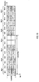
-
FIG.1 is a block diagram illustrating a configuration of a base station according to an embodiment of the present invention; -
FIG.2 is a block diagram illustrating a configuration of a mobile station according to the embodiment of the present invention; -
FIG.3 illustrates an Lch mapping method according to the embodiment of the present invention; -
FIG.4 illustrates a Dch mapping method according tomapping method 1 of the embodiment of the present invention; -
FIG.5 illustrates an allocation example according tomapping method 1 of the embodiment of the present invention; -
FIG.6 illustrates a Dch mapping method according tomapping method 1 of the embodiment of the present invention (case of division into three portions); -
FIG.7 illustrates a Dch mapping method according tomapping method 2 of the embodiment of the present invention; -
FIG.8 illustrates an allocation example according tomapping method 2 of the embodiment of the present invention; -
FIG.9 illustrates a Dch mapping method according tomapping method 3 of the embodiment of the present invention (when using mapping method 1); -
FIG.10 illustrates a Dch mapping method according tomapping method 3 of the embodiment of the present invention (when using mapping method 2); -
FIG.11 illustrates a Dch mapping method according tomapping method 4 of the embodiment of the present invention (when using mapping method 1); -
FIG.12 illustrates a Dch mapping method according tomapping method 4 of the embodiment of the present invention (when using mapping method 2); -
FIG.13 illustrates a Dch mapping method according tomapping method 5 of the embodiment of the present invention (when using mapping method 1); and -
FIG.14 illustrates a Dch mapping method according tomapping method 5 of the embodiment of the present invention (when using mapping method 2). - An embodiment of the present invention will be described below in detail with reference to the accompanying drawings.
-
FIG.1 illustrates a configuration ofbase station 100 according to the present embodiment.Base station 100 divides a plurality of subcarriers comprised of an OFDM symbol, which is a multicarrier signal, into a plurality of RBs and uses Dch and Lch for each RB of the plurality of RBs. Furthermore, one of Dch and Lch is allocated to one mobile station in the same subframe. -
Base station 100 is provided with n (n is the number of mobile stations (MSs) with whichbase station 100 can communicate) encoding/modulation sections 101-1 to 101-n each comprising encodingsection 11 andmodulation section 12 for Dch data, n encoding/modulation sections 102-1 to 102-n each comprising encodingsection 21 andmodulation section 22 for Lch data and n demodulation/decoding sections 115-1 to 115-n each comprisingdemodulation section 31 anddecoding section 32. - In encoding/modulation sections 101-1 to 101-n, encoding
section 11 performs encoding processing using a turbo code or the like onDch data # 1 to #n for each ofmobile stations # 1 to #n andmodulation section 12 performs modulation processing on the encoded Dch data to thereby generate a Dch data symbol. - In encoding/modulation sections 102-1 to 102-n, encoding
section 21 performs encoding processing using a turbo code or the like onLch data # 1 to #n for each ofmobile stations # 1 to #n andmodulation section 22 performs modulation processing on the encoded Lch data to thereby generate an Lch data symbol. The coding rate and modulation scheme in this case follows MCS (Modulation and Coding Scheme: MCS) information inputted fromadaptive control section 116. -
Allocation section 103 allocates the Dch data symbol and Lch data symbol to each subcarrier comprised of an OFDM symbol according to the control fromadaptive control section 116 and outputs the OFDM symbol to multiplexingsection 104. In this case,allocation section 103 collectively allocates the Dch data symbols and Lch data symbols for each RB. Furthermore, when allocating the Lch data symbols,allocation section 103 groups the plurality of RBs into a plurality of groups and allocates Lchs in RB group units. Furthermore, when using a plurality of Dchs for the Dch data symbol of one mobile station,allocation section 103 uses Dchs with continuous channel numbers. Furthermore,allocation section 103 allocates the Dch data symbol to a plurality of RBs to which one Dch is mapped at intervals of an integer multiple of the number of RBs constituting one RB group. In each RB, the mapping positions of Dch and Lch are associated with each other in advance. That is,allocation section 103 stores a mapping pattern, which is the association between Dchs and Lchs, and RBs in advance and allocates the Dch data symbol and Lch data symbol to each RB according to the mapping pattern. Details of the Dch mapping method according to the present embodiment will be described later. Furthermore,allocation section 103 outputs allocation information of the Dch data symbol (information indicating which mobile station's Dch data symbol is allocated to which RBs) and allocation information of the Lch data symbol (information indicating which RBs are allocated to the Lch data symbol of which mobile station) to controlinformation generation section 105. For example, the allocation information of the Dch data symbol only includes the first channel number and the last channel number of the continuous channel numbers. - Control
information generation section 105 generates control information including the allocation information of the Dch data symbol, allocation information of the Lch data symbol and MCS information inputted fromadaptive control section 116 and outputs the control information toencoding section 106. -
Encoding section 106 performs encoding processing on the control information andmodulation section 107 performs modulation processing on the encoded control information and outputs the control information tomultiplexing section 104. - Multiplexing
section 104 multiplexes each data symbol inputted fromallocation section 103 with control information and outputs the multiplexing result to IFFT (Inverse Fast Fourier Transform)section 108. Multiplexing of control information is performed, for example, every subframe. According to the present embodiment, multiplexing of control information may be one of time domain multiplexing and frequency domain multiplexing. -
IFFT section 108 performs IFFT on a plurality of subcarriers comprised of a plurality of RBs to which control information and data symbol are allocated, to generate an OFDM symbol, which is a multicarrier signal. - CP (Cyclic Prefix) adding
section 109 adds the same signal as the last portion of the OFDM symbol to the head of the OFDM symbol as a CP. -
Radio transmitting section 110 performs transmission processing such as D/A conversion, amplification and up-conversion on the OFDM symbol with a CP and transmits the OFDM symbol fromantenna 111 to each mobile station. - On the other hand,
radio receiving section 112 receives n OFDM symbols at the same time transmitted from maximum n mobile stations viaantenna 111 and performs reception processing such as down-conversion, A/D conversion on these OFDM symbols. -
CP removing section 113 removes the CP from the OFDM symbol after the reception processing. - FFT (Fast Fourier Transform)
section 114 performs FFT on the OFDM symbol without a CP to obtain a signal for each mobile station multiplexed in the frequency domain. Here, the respective mobile stations transmit signals using subcarriers different from each other or RBs different from each other and a signal for each mobile station includes received quality information for each RB reported from each mobile station. Each mobile station can measure the received quality of each RB using received SNR, received SIR, received SINR, received CINR, received power, interference power, bit error rate, throughput and MCS or the like that can achieve a certain error rate. Furthermore, the received quality information may be expressed as "CQI" (Channel Quality Indicator), "CSI" (Channel State Information) and so on. - In demodulation/decoding sections 115-1 to 115-n,
demodulation section 31 performs demodulation processing on the signal after the FFT anddecoding section 32 performs decoding processing on the demodulated signal. The received data is thereby obtained. Of the received data, the received quality information is inputted toadaptive control section 116. -
Adaptive control section 116 performs adaptive control over Lch data based on the received quality information for each RB reported from each mobile station. That is, for encoding/modulation sections 102-1 to 102-n,adaptive control section 116 selects MCS whereby a required error rate can be satisfied for each RB group based on the received quality information for each RB and outputs the MCS information, and forallocation section 103,adaptive control section 116 performs frequency scheduling to determine to which RB groupLch data # 1 to #n should be allocated respectively using a scheduling algorithm such as a Max SIR method or Proportional Fairness method. Furthermore,adaptive control section 116 outputs MCS information for each RB group to controlinformation generation section 105. - Next, the configuration of
mobile station 200 according to the present embodiment is shown inFIG.2 .Mobile station 200 receives a multicarrier signal, which is an OFDM symbol comprised of a plurality of subcarriers divided into a plurality of RBs, from base station 100 (FIG.1 ). Furthermore, Dch and Lch are used for each RB in a plurality of RBs. Furthermore, one of Dch and Lch is allocated tomobile station 200 in the same subframe. - In
mobile station 200,radio receiving section 202 receives the OFDM symbol transmitted frombase station 100 viaantenna 201 and performs reception processing such as down-conversion or A/D conversion on the OFDM symbol. -
CP removing section 203 removes CP from the OFDM symbol after the reception processing. -
FFT section 204 performs FFT on the OFDM symbol without a CP to obtain a received signal in which control information and data symbols are multiplexed. -
Demultiplexing section 205 demultiplexes the received signal after the FFT into a control signal and data symbol.Demultiplexing section 205 then outputs the control signal to demodulation/decoding section 206 and outputs the data symbol todemapping section 207. - In demodulation/
decoding section 206,demodulation section 41 performs demodulation processing on the control signal anddecoding section 42 performs decoding processing on the demodulated signal. Here, the control information includes Dch data symbol allocation information, Lch data symbol allocation information and MCS information. Demodulation/decoding section 206 then outputs the Dch data symbol allocation information and the Lch data symbol allocation information out of the control information todemapping section 207. -
Demapping section 207 extracts the data symbol allocated to that mobile station from among the plurality of RBs to which data symbols inputted fromdemultiplexing section 205 are allocated based on the allocation information inputted from demodulation/decoding section 206. In each RB, mapping positions of Dchs and Lchs are associated with each other in advance as with base station 100 (FIG.1 ). That is,demapping section 207 stores the same mapping pattern as that ofallocation section 103 ofbase station 100 and extracts Dch data symbols and Lch data symbols from a plurality of RBs according to the mapping pattern. Furthermore, when extracting the Lch data symbol,demapping section 207 extracts Lchs in RB group units in which a plurality of RBs are grouped into a plurality of groups. Furthermore, as described above, when a plurality of Dchs are used for a Dch data symbol of one mobile station,allocation section 103 of base station 100 (FIG.1 ) uses Dchs with continuous channel numbers. Furthermore, the allocation information included in the control information frombase station 100 indicates only the first channel number and the last channel number among the continuous channel numbers of Dchs used for the Dch data symbol. Thus,demapping section 207 specifies Dchs used for the Dch data symbol allocated to that mobile station based on the first channel number and the last channel number indicated in the allocation information. To be more specific,demapping section 207 identifies a plurality of continuous Dchs from the first channel number indicated in the allocation information to the last channel number indicated in the allocation information as Dchs used for the Dch data symbol allocated to that mobile station.Demapping section 207 then extracts the RB associated with the specified channel number of the identified Dch and outputs the data symbol allocated to the extracted RB to demodulation/decoding section 208. - In demodulation/
decoding section 208,demodulation section 51 performs demodulation processing on the data symbol inputted fromdemapping section 207 anddecoding section 52 performs decoding processing on the demodulated signal. The received data is thereby obtained. - On the other hand, in encoding/
modulation section 209, encodingsection 61 performs encoding processing using a turbo code or the like on the transmission data andmodulation section 62 performs modulation processing on the encoded transmission data to generate a data symbol. Here,mobile station 200 transmits transmission data using subcarriers or RBs different from those of other mobile stations and the transmission data includes receiving quality information for each RB. -
IFFT section 210 performs IFFT on a plurality of subcarriers comprised of a plurality of RBs to which data symbols inputted from encoding/modulation section 209 are allocated, to generate an OFDM symbol, which is a multicarrier signal. -
CP adding section 211 adds the same signal as the last portion of the OFDM symbol to the head of the OFDM symbol as a CP. -
Radio transmitting section 212 performs transmission processing such as D/A conversion, amplification and up-conversion on the OFDM symbol with a CP and transmits the OFDM symbol to base station 100 (FIG.1 ) fromantenna 201. - Next, the Dch channel mapping method according to the present embodiment will be described. In the following explanations, a case will be described as an example of configuration where a plurality of subcarriers comprised of one OFDM symbol are uniformly divided into 14 RBs of
RBs # 1 to #14 as shown inFIG.3 . Furthermore,Lch # 1 to #14 orDch # 1 to #14 is formed with each RB andadaptive control section 116 controls channels used by each mobile station. Furthermore, Lchs are allocated to each mobile station in RB group units. Here, as shown inFIG.3 ,RBs # 1 to #14 are grouped into RBgroups RBGs # 1 to #7. Here, suppose the number of RBs constituting one RB group (hereinafter referred to as "RB group size") is 2. Therefore, as shown inFIG.3 ,Lch # 1 andLch # 2 mapped toRB # 1 andRB # 2 constituting RBG1 are always allocated at the same time andLch # 3 andLch # 4 mapped toRB # 3 andRB # 4 constituting RBG2 are always allocated at the same time. The same applies toLchs # 5 to #14 constitutingRBGs # 3 to #7 respectively. Furthermore, the Lch configuration in each RB shown inFIG.3 and the Dch configuration in each RB shown below are associated with each other in advance inallocation section 103. - Here, since frequency scheduling is performed on Lch in RB units, each RB used for Lch includes an Lch data symbol for only one mobile station. That is, one Lch corresponding to one mobile station is formed with one RB. Therefore, as shown in
FIG.3 ,Lchs # 1 to #12 are mapped toRBs # 1 to #12 respectively. That is, the allocation unit of each Lch is "1 RB × 1 subframe." - On the other hand, since frequency diversity transmission is carried out for Dch, RB used for Dch includes a plurality of Dch data symbols. Here, each RB used for Dch is temporally divided into two subblocks and different Dchs are mapped to each subblock. That is, a plurality of different Dchs are time-domain-multiplexed in 1 RB. Furthermore, one Dch is formed with two different RB subblocks. That is, the allocation unit of each Dch is "(1 RB × 1/2 subframe) × 2" and is the same as the allocation unit of each Lch.
- In the present mapping method, one Dch is mapped at intervals of an integer multiple of the RB group size for a plurality of RBs.
- That is, the RB interval Gap of RBs in which one Dch is mapped is given by following
equation 1, - [1]

Next, the relational expression between the channel number of Dch and an RB number of RB in which the Dch is mapped is shown. Nd RB numbers (indexes) j in which Dch #k (k = 1 to 12) are mapped are given by followingequation 2. - [2]

- Here, since Nrb = 14, Nd = 2, RBGsize = 2, RB interval Gap is 6 (= floor((14/2)/2)x2) according to
equation 1. Therefore,equation 2 above is j = (((k - 1) + 6·p)mod 12) + 1 (p = 0, 1), where k = 1, 2, ..., 12. Thus, one Dch is mapped in a distributed manner to two RBs of RB #(k) and RB #(k + 6) which are 6 RBs apart in the frequency domain. In other words, one Dch is distributedly mapped toRBs 6 RBs apart which is an integer multiple (here, three times) of the RB group size (RBGsize = 2) in the frequency domain. This RB interval (RB interval 6) is a maximum interval equal to or below Nrb/Nd (= 14/2) among intervals of integer multiples of the RB group size (RBGsize = 2). - To be more specific, as shown in
FIG.4 ,Dchs # 1 and #7 are mapped to RB #1 (RB #7),Dchs # 2 and #8 are mapped to RB #2 (RB #8),Dchs # 3 and #9 are mapped to RB #3 (RB #9),Dchs # 4 and #10 are mapped to RB #4 (RB #10),Dchs # 5 and #11 are mapped to RB #5 (RB #11) andDchs # 6 and #12 are mapped to RB #6 (RB #12). That is, according to the present mapping method, the maximum number of Dchs thatallocation section 103 can allocate to RBs is 12. - Next,
FIG.5 illustrates a allocation example in allocation section 103 (FIG.1 ) ofbase station 100 when four Dchs are allocated to a Dch data symbol of one mobile station. Here, for simplicity of explanation,Dch # 1, #2, #7 and #8 are allocated so that no odd subblocks are produced in RBs used for Dchs. Furthermore,allocation section 103 stores the Dch mapping pattern shown inFIG.4 in advance and allocates Dch data symbols to RBs according to the mapping pattern shown inFIG.4 . - As shown in
FIG.5 ,allocation section 103 allocates Dch data symbols to the subblock ofRB # 1 and subblock ofRB # 7 constitutingDch # 1, the subblock ofRB # 2 and subblock ofRB # 8 constitutingDch # 2, the subblock ofRB # 1 and subblock ofRB # 7 constitutingDch # 7, and the subblock ofRB # 2 and subblock ofRB # 8 constitutingDch # 8. That is, as shown inFIG.5 , Dch data symbols are allocated toRBs # 1, #2, #7 and #8. Therefore, four Dchs are allocated to RBsubblocks RBs # 1 and #2 constituting RBG1, andRBs # 7 and #8 constituting RBG4 covering all RBs. - Furthermore, as shown in
FIG.5 ,allocation section 103 allocates Lch data symbols to the rest of the RBs other than the RBs to which Dch data symbols are allocated, that is,RBs # 3 to #6 andRBs # 9 to #14. As described above, each Lch is allocated to RB group units. Thus, as shown inFIG.5 ,allocation section 103 allocates Lch data symbols toRB # 3 andRB # 4 constituting RBG2 in whichLch # 3 andLch # 4 are mapped respectively,RB # 5 andRB # 6 constituting RBG3 in whichLch # 5 andLch # 6 are mapped respectively,RB # 9 andRB # 10 constituting RBG5 in whichLch # 9 andLch # 10 are mapped respectively,RB # 11 andRB # 12 constituting RBG6 in whichLch # 11 andLch # 12 are mapped respectively andRB # 13 andRB # 14 constituting RBG7 in whichLch # 13 andLch # 14 are mapped respectively. That is,Lchs # 3 to #6 andLchs # 9 to #14 shown inFIG.3 are used for Lch data symbols. Thus, when Lch data symbols are allocated to RBs other than the RBs to which Dch data symbols are allocated,allocation section 103 can allocate Lch data symbols in RB group units covering all RBs. - Next, an extraction example in
demapping section 207 of mobile station 200 (FIG.2 ) will be described where Dch data symbols using four Dchs are allocated tomobile station 200. Here, for simplicity of explanation,Dchs # 1, #2, #7 and #8 are used for Dch data symbols so that no odd subblocks are produced in RBs. Furthermore, as withallocation section 103,demapping section 207 stores the Dch mapping pattern shown inFIG.4 in advance and extracts Dch data symbols from a plurality of RBs according to the mapping pattern shown inFIG.4 . - As with
allocation section 103, as shown inFIG.5 ,demapping section 207 extractsDch # 1 formed with the subblock ofRB # 1 and the subblock ofRB # 7,Dch # 2 formed with the subblock ofRB # 2 and the subblock ofRB # 8,Dch # 7 formed with the subblock ofRB # 1 and the subblock ofRB # 7 andDch # 8 formed with the subblock ofRB # 2 and the subblock ofRB # 8. That is, as shown inFIG.5 ,demapping section 207 extracts Dch data symbols allocated toRBs # 1, #2, #7 and #8 as data symbols directed to the subject station. In other words, as shown inFIG.5 ,demapping section 207 extracts four Dchs allocated to RBG1 formed withRBs # 1 and #2 and RBG4 formed withRBs # 7 and #8 covering all RBs as data symbols directed to the subject station. - Thus, according to the present mapping method, the RB interval of RBs to which one Dch is mapped is set to an integer multiple of the RB group size of the RB group used for Lch allocation (three times in the present mapping method). When Lchs are allocated to the rest of the RBs after Dchs are allocated, this allows the base station to allocate Lchs in RB group units without producing any RBs that cannot be used. Therefore, according to the present mapping method, even when frequency scheduling transmission and frequency diversity transmission are at the same time carried out, it is possible to prevent the system throughput from deteriorating due to deterioration of the utilization efficiency of communication resources. Furthermore, according to the present mapping method, Lchs can be allocated without producing any unoccupied RBs and the throughput of Lchs can therefore be improved. Furthermore, according to the present mapping method, Lchs are allocated to RB group units, and therefore the amount of control information for indicating the Lch allocation result can be reduced.
- Here, with 14 RBs (
RBs # 1 to #14) shown inFIG.4 , a maximum of 14 Dchs can be allocated. By contrast, according to the present mapping method, a maximum of 12 Dchs can be allocated as described above. That is, according to the present mapping method, the number of Dchs that can be allocated are reduced by an amount corresponding to the RB group size (two Dchs inFIG.4 ) at a maximum. However, since the applications of Dchs are limited to data communication when a mobile station moves at a high speed or the like, it is extremely rare that Dchs are allocated to all RBs. Therefore, there is substantially no deterioration of system throughput due to a decrease in the number of Dchs that can be allocated using the present mapping method. Moreover, the improvement in the system throughput by allocating Lchs without producing any unoccupied RBs # using the present mapping method becomes more significant than the deterioration of system throughput. - Although a case has been described in the present mapping method where one RB is divided into two portions when Dchs are used, the number of divisions is not limited to 2, but one RB may be divided into three portions. For example,
FIG.6 illustrates a mapping method where one RB is divided into three portions when Dchs are used. In the mapping method illustrated inFIG.6 , when, for example, six Dchs are mapped, Dchs can be mapped within RB groups covering all RB subblocks, and therefore effects similar to those of the present mapping method can be obtained. Furthermore, as shown inFIG.6 , since one Dch is configured distributed across three RBs, the diversity effect can be improved more than the case of division into two portions. - The present mapping method is the same as
mapping method 1 in that one Dch is mapped at intervals of an integer multiple of the RB group size among a plurality of RBs, but the present mapping method is different frommapping method 1 in that one Dch is mapped at the maximum interval among possible intervals of integer multiples of the RB group size. - That is, RB interval Gap between RBs to which one Dch is mapped is given by following
equation 3. - [3]

equation 1.
Nd RB numbers (indexes) j to which Dch #k (k = 1 to 12) are mapped are given byequation 4. - [4]

Wgap + 1, Wgap + 2, ..., Wgap×Nd are mapped to the last-half RB subblocks. - Here, since Nrb = 14, Nd = 2, RBGsize = 2 and Wgap = 6, the RB interval Gap is 8 (= floor((14/2)/2)×2 + 6) according to
equation 3. Therefore, aboveequation 4 becomes j = ((k - 1)mod(6)) + 8xp (p = 0, 1). where, k = 1, 2, ..., 12. Thus, one Dch is mapped in a distributed manner to two RBs of RB #(k) and RB #(k + 8) which are 8 RBs apart in the frequency domain. In other words, one Dch is distributedly mapped toRBs 8 RBs apart which is an integer multiple (here, four times) of the RB group size (RBGsize = 2) in the frequency domain. Furthermore, according to the present mapping method (Equation 3), the RB interval increases by the number of RBs of RB groups to which Dchs are not allocated compared to the RB interval (Equation 1) ofmapping method 1. To be more specific, according to mapping method 1 (FIG.4 ), Dchs are not mapped to two RBs ofRBs # 13 and #14. Therefore, the RB interval Gap according to the present mapping method becomes 8 RBs which is greater by 2 RBs than the RB interval of 6 RBs according tomapping method 1. This is because, according to mapping method 1 (FIG.4 ), RBs in which no Dch is mapped are allocated to an end of all the RBs, whereas according to the present mapping method, RBs in which no Dch is mapped are allocated at the central part of all the RBs. - To be more specific, as shown in
FIG.7 ,Dchs # 1 and #7 are mapped to RB #1 (RB #9),Dchs # 2 and #8 are mapped to RB #2 (RB #10),Dchs # 3 and #9 are mapped to RB #3 (RB #11),Dchs # 4 and #10 are mapped to RB #4 (RB #12),Dchs # 5 and #11 are mapped to RB #5 (RB #13), andDchs # 6 and #12 are mapped to RB #6 (RB #14). That is, according to the present mapping method, the maximum number of Dchs that can be allocated to RBs byallocation section 103 is 12 as withmapping method 1. Furthermore, according to mapping method 1 (FIG.4 ), RBs in which no Dch is mapped arelast RBs # 13 and #14 ofRBs # 1 to #14, whereas according to the present mapping method, RBs in which no Dch is mapped areRBs # 7 and #8 as shown inFIG.7 . That is, no Dch is mapped to the central part of all the RBs. Thus, two RB subblocks constituting each Dch are mapped extending to a maximum extent overRBs # 1 to #6 andRBs # 9 to #14 on both sides ofRBs # 7 and #8. That is,Dchs # 1 to #12 are mapped at a maximum interval (interval of 8 RBs) among possible intervals of integer multiples of the RB group size out of 14 RBs. - Next, as with
mapping method 1,FIG.8 illustrates a mapping example where four Dchs are used for Dch data symbols of one mobile station. Here,Dchs # 1, #2, #7 and #8 are allocated as withmapping method 1. Furthermore,allocation section 103 stores the Dch mapping pattern shown inFIG.7 in advance and allocates Dch data symbols to RBs according to the mapping pattern shown inFIG.7 . - As shown in
FIG.8 ,allocation section 103 allocates Dch data symbols to the subblock ofRB # 1 and the subblock ofRB # 9 constitutingDch # 1, the subblock ofRB # 2 and the subblock ofRB # 10 constitutingDch # 2, the subblock ofRB # 1 and the subblock ofRB # 9 constitutingDch # 7, and the subblock ofRB # 2 and the subblock ofRB # 10 constitutingDch # 8. That is, Dch data symbols are allocated toRBs # 1, #2, #9 and #10 as shown inFIG.8 . That is, the four Dchs are allocated toRBs # 1 and #2 constituting RBG1, andRBs # 9 and #10 constituting RBG5 covering all RB subblocks. - Furthermore, as shown in
FIG.8 ,allocation section 103 allocates Lch data symbols to the rest of theRBs # 3 to #8 andRBs # 11 to #14 other than the RBs to which the Dch data symbols have been allocated. Here,allocation section 103 allocates Lch data symbols in RB group units as withmapping method 1. To be more specific, as shown inFIG.8 ,allocation section 103 allocates Lch data symbols to two RBs constitutingRBGs # 2, #3, #4, #6 and #7 respectively. That is,Lchs # 3 to #8 andLchs # 11 to #14 shown inFIG.3 are used for the Lch data symbols. Thus, when allocating Lch data symbols to blocks other than the RBs to which the Dch data symbols have been allocated,allocation section 103 can allocate the Lch data symbols in RB group units covering all RBs as withmapping method 1. - Next, an extraction example in
demapping section 207 of mobile station 200 (FIG.2 ) will be described where Dch data symbols using four Dchs are allocated tomobile station 200. Here,Dchs # 1, #2, #7 and #8 are used for Dch data symbols as withmapping method 1. Furthermore,demapping section 207 stores the Dch mapping pattern shown inFIG.7 in advance as withallocation section 103 and extracts Dch data symbols from a plurality of RBs according to the mapping pattern shown inFIG.7 . - As with
allocation section 103, as shown inFIG.8 ,demapping section 207 extractsDch # 1 formed with the subblock ofRB # 1 and the subblock ofRB # 9,Dch # 2 formed with the subblock ofRB # 2 and the subblock ofRB # 10,Dch # 7 formed with the subblock ofRB # 1 and the subblock ofRB # 9, andDch # 8 formed with the subblock ofRB # 2 and the subblock ofRB # 10. That is, as shown inFIG.8 ,demapping section 207 extracts Dch data symbols allocated toRBs # 1, #2, #7 and #8 as data symbols directed to the subject station. In other words, as shown inFIG.8 ,demapping section 207 extracts four Dchs allocated to RBG1 formed withRBs # 1 and #2, and RBG5 formed withRBs # 9 and #10 covering all RBs as data symbols directed to the subject station. - Here, in
FIG.8 , as in the case of mapping method 1 (FIG.5 ), Dch data symbols are allocated to four RBs and Lch data symbols are allocated to 10 RBs. However, according to the present mapping method as shown inFIG.8 , Dch data symbols are allocated in a distributed manner toRB # 1,RB # 2,RB # 9 andRB # 10, and therefore the interval thereof is longer by the RB interval where no Dch is mapped (2-RB interval ofRBs # 7 and #8) than by mapping method 1 (FIG.5 ). Therefore, the present mapping method can improve the frequency diversity effect. - By this means, the present mapping method maps one Dch at a maximum interval (8-RB interval four times the RB group size in
FIG.7 ) among possible intervals of integer multiples of the RB group size. By this means, Lchs can be allocated in RB group units while maximizing the RB interval of one Dch without producing any RB that cannot be used. Therefore, according to the present mapping method, it is possible to obtain effects similar to those ofmapping method 1 and improve the frequency diversity effect compared tomapping method 1. - Although a case has been described in the present mapping method where one RB is divided into two portions when Dchs are used, the number of divisions of one RB is not limited to two, but the number of divisions of one RB may be three or more as in the case of
mapping method 1. - The present mapping method is the same as
mapping method 1 in that one Dch is mapped at intervals of an integer multiple of the RB group size among a plurality of RBs, but the present mapping method differs frommapping method 1 in that a plurality of Dchs with continuous channel numbers are mapped to one RB. - Hereinafter, the present mapping method will be described more specifically. Here, one Dch is mapped to two RBs which are mapped in a distributed manner at intervals of 6 RBs as with mapping method 1 (
FIG.4 ). - As shown in
FIG.9 ,Dchs # 1 and #2 with continuous channel numbers are mapped to RB #1 (RB #7). Likewise,Dchs # 3 and #4 are mapped to RB #2 (RB #8),Dchs # 5 and #6 are mapped to RB #3 (RB #9),Dchs # 7 and #8 are mapped to RB #4 (RB #10),Dchs # 9 and #10 are mapped to RB #5 (RB #11) andDchs # 11 and #12 are mapped to RB #6 (RB #12). - Thus, since one Dch is mapped to two RBs at intervals of 6 RBs, when allocating Lchs to the rest of the RBs after allocating Dchs as with
mapping method 1, it is possible to allocate Lchs in RB group units without producing any RBs that cannot be used. Furthermore, since a plurality of Dchs with continuous channel numbers are mapped to one RB, when one mobile station uses a plurality of Dchs, all the one RB sub blocks are used first and then the other RBs are used. Therefore, data symbols are allocated to some subblocks of a plurality of subblocks constituting one RB, and on the other hand, it is possible to minimize the possibility that other subblocks may not be further used. This makes it possible to improve the utilization efficiency of Dch resources. - Furthermore, as with
mapping method 1,allocation section 103 of base station 100 (FIG.1 ) anddemapping section 207 of mobile station 200 (FIG.2 ) store the Dch mapping pattern shown inFIG.9 , which is the correspondence between RBs and Dchs, in advance.Allocation section 103 ofbase station 100 then allocates Dch data symbols to RBs according to the Dch mapping pattern shown inFIG.9 . On the other hand,demapping section 207 ofmobile station 200 extracts Dch data symbols directed to the subject station from a plurality of RBs according to the Dch mapping pattern shown inFIG.9 as withallocation section 103. - By this means, the present mapping method maps a plurality of Dchs with continuous channel numbers in one RB, and thereby increases the probability that data symbols may be allocated to all RB subblocks used for Dchs. Therefore, it is possible to prevent deterioration of system throughput due to deterioration of the utilization efficiency of communication resources compared to
mapping method 1. - As with mapping method 2 (
FIG.7 ), the present mapping method may map one Dch at the maximum interval among possible intervals of integer multiples of the RB group size. To be more specific, as shown inFIG.10 , one Dch may be mapped to RBs mapped in a distributed manner at intervals of 8 RBs. This makes it possible to achieve a diversity effect similar to that ofmapping method 2 while achieving effects similar to those of the present mapping method. - The present mapping method is the same as
mapping method 1 in that one Dch is mapped at intervals of an integer multiple of the RB group size of a plurality of RBs, but the present mapping method is different frommapping method 1 in that a plurality of Dchs with continuous channel numbers are mapped to different RBs constituting one RB group. - Hereinafter, the present mapping method will be described more specifically. Here, as with mapping method 1 (
FIG.4 ), one Dch is mapped to two RBs mapped in a distributed manner at intervals of 6 RBs. - As shown in
FIG.11 ,Dchs # 1 and #3 are mapped to RB #1 (RB #7),Dchs # 2 and #4 are mapped to RB #2 (RB #8),Dchs # 5 and #7 are mapped to RB #3 (RB #9),Dchs # 6 and #8 are mapped to RB #4 (RB #10),Dchs # 9 and #11 are mapped to RB #5 (RB #11) andDchs # 10 and #12 are mapped to RB #6 (RB #12). - That is, as shown in
FIG.11 ,Dchs # 1 to #4 with continuous channel numbers are mapped toRBs # 1 and #2 (RBs # 7 and #8) constituting RBG1 (RBG4). Furthermore, in RBG1 (RBG4), Dch #1 (Dch #3) and Dch #2 (Dch #4) with continuous channel numbers amongDchs # 1 to #4 are mapped to different RBs ofRB # 1 and #2 respectively. Furthermore, as shown inFIG.11 ,Dch # 3 andDch # 2 with continuous channel numbers are also mapped to different RBs ofRBs # 1 and #2 respectively. The same applies to RBG2 (RBG5) and RBG3 (RBG6). - Thus, since a plurality of Dchs with continuous channel numbers are mapped to one RB group, even when one mobile station uses a plurality of Dchs, RBs are used in RB group units for Dchs. Therefore, when RBs other than the RBs used for Dchs are allocated to Lchs, RBs can also be used in RB group units for Lchs. That is, since RBs can be used exhaustively, it is possible to prevent deterioration in the utilization efficiency of communication resources more than
mapping method 1. Furthermore, in the RB group, Dchs with continuous channel numbers are mapped to different RBs, and therefore the diversity effect can be improved. - Furthermore, as with
mapping method 1,allocation section 103 of base station 100 (FIG.1 ) anddemapping section 207 of mobile station 200 (FIG.2 ) store the Dch mapping pattern shown inFIG.11 , which is the correspondence between RBs and Dchs, in advance.Allocation section 103 ofbase station 100 then allocates Dch data symbols to RBs according to the Dch mapping pattern shown inFIG.11 . On the other hand, as withallocation section 103,demapping section 207 ofmobile station 200 extracts Dch data symbols directed to the subject station from a plurality of RBs according to the Dch mapping pattern shown inFIG.11 . - By this means, the present mapping method maps a plurality of Dchs with continuous channel numbers in different RBs constituting one RB group respectively. By this means, even when a plurality of Dchs are used, the plurality of Dchs are collectively allocated in RB group units. That is, even when one mobile station uses a plurality of Dchs, Dchs are allocated to RB units, and therefore Lchs can also be allocated in RB group units. Thus, the present mapping method can prevent deterioration of system throughput due to deterioration of the utilization efficiency of communication resources compared to
mapping method 1. Furthermore, since different Dchs with continuous channel numbers are allocated to different RBs within one RB group, the frequency diversity effect can be further improved. - As with mapping method 2 (
FIG.7 ), the present mapping method may also map one Dch at the maximum interval among possible intervals of integer multiples of the RB group size. To be more specific, as shown inFIG.12 , one Dch may be mapped to RBs mapped in a distributed manner at intervals of 8 RBs. This makes it possible to achieve a diversity effect similar to that ofmapping method 2 while achieving effects similar to those of the present mapping method. - The present mapping method is the same as
mapping method 4 in that a plurality of Dchs with continuous channel numbers are mapped to different RBs constituting one RB group, but the present mapping method is different frommapping method 4 in that a plurality of Dchs with discontinuous channel numbers are mapped to mutually neighboring RBs among a plurality of RBs constituting mutually neighboring RB groups. - Hereinafter, the present mapping method will be described more specifically. Here, as with mapping method 1 (
FIG.4 ), one Dch is mapped to two RBs mapped in a distributed manner at intervals of 6 RBs. - As shown in
FIG.13 ,Dchs # 1 and #7 are mapped to RB #1 (RB #7),Dchs # 2 and #8 are mapped to RB #2 (RB #8),Dchs # 5 and #11 are mapped to RB #3 (RB #9),Dchs # 6 and #12 are mapped to RB #4 (RB #10),Dchs # 3 and #9 are mapped to RB #5 (RB #11), andDchs # 4 and #10 are mapped to RB #6 (RB #12). - That is, as shown in
FIG.13 ,Dchs # 1 and #2 (Dchs # 7 and #8) with continuous channel numbers are mapped toRBs # 1 and #2 constituting RBG1. Likewise,Dchs # 5 and #6 (Dchs # 11 and #12) with continuous channel numbers are mapped toRBs # 3 and #4 constituting RBG2, andDchs # 3 and #4 (Dchs # 9 and #10) with continuous channel numbers are mapped toRBs # 5 and #6 constituting RBG3. - Furthermore, a plurality of different Dchs with discontinuous channel numbers are mapped to
RB # 2 andRB # 3, which are mutually neighboring RBs (that is, RBs on the boundary between RBG1 and RBG2) of RBs constituting mutually neighboring RBG1 (RBs # 1 and #2) and RBG2 (RBs # 3 and #4). To be more specific, as shown inFIG.13 ,Dch # 2 and Dch #5 (Dch # 8 and Dch #11) with discontinuous channel numbers are mapped toRB # 2 andRB # 3 respectively. Likewise,Dch # 6 and Dch #3 (Dch # 12 and Dch #9) with discontinuous channel numbers are mapped to mutually neighboringRB # 4 andRB # 5 amongRB # 3 and #4 constituting RBG2, andRB # 5 and #6 constituting RBG3. The same applies to RBG4 to RBG6. - By this means, at least one set of Dchs with continuous channel numbers is mapped to one RB group. Furthermore, channel numbers of Dchs mapped to mutually neighboring RBs among a plurality of RBs constituting mutually neighboring RB groups respectively are discontinuous. In other words, Dchs with continuous channel numbers among Dchs mapped to different RB groups are mapped to RBs distributed in the frequency domain.
- Thus, when one mobile station uses many Dchs,
allocation section 103 allocates Dchs to RBs distributed in the frequency domain, and thereby provide frequency diversity effect. On the other hand, when one mobile station uses a fewer Dchs,allocation section 103 can collectively allocate Dchs within an RB group. By this means, when RBs other than the RBs used for Dchs are allocated to Lchs, RBs can also be used in RB group units for Lchs. That is, RBs can be used exhaustively, and it is therefore possible to prevent deterioration of the utilization efficiency of communication resources. - Furthermore, as with
mapping method 1,allocation section 103 of base station 100 (FIG.1 ) anddemapping section 207 of mobile station 200 (FIG.2 ) store the Dch mapping pattern shown inFIG.13 , which is the correspondence between RBs and Dchs, in advance.Allocation section 103 ofbase station 100 then allocates Dch data symbols to RBs according to the Dch mapping pattern shown inFIG.13 . On the other hand, as withallocation section 103,demapping section 207 ofmobile station 200 extracts Dch data symbols directed to the subject station from a plurality of RBs according to the Dch mapping pattern shown inFIG.13 . - By this means, the present mapping method maps a plurality of Dchs with discontinuous channel numbers in mutually neighboring RBs among a plurality of RBs constituting mutually neighboring RB groups. Thus, as with
mapping method 1, it is possible to prevent deterioration of system throughput due to deterioration in the utilization efficiency of communication resources when one mobile station uses a fewer Dchs, and improve the frequency diversity effect when one mobile station uses many Dchs. - According to the present mapping method, one Dch may be mapped at the maximum interval among possible intervals of integer multiples of the RB group size as with mapping method 2 (
FIG.7 ). To be more specific, as shown inFIG.14 , one Dch may be mapped to RBs mapped in a distributed manner at intervals of 8 RBs. This makes it possible to achieve a diversity effect similar to that ofmapping method 2 while achieving effects similar to those of the present mapping method. -
Mapping methods 1 to 5 according to the present embodiment have been described so far. - Thus, according to the present embodiment, it is possible to prevent deterioration in the utilization efficiency of communication resources even when frequency scheduling transmission through Lchs and frequency diversity transmission through Dchs are carried out at the same time.
- An embodiment of the present invention has been described so far.
- In the above described embodiment, the channel mapping method for mapping Dchs in RBs depends on the number of all RBs (Nrb) determined by the system bandwidth as shown in
equation 1 orequation 3. Therefore, the base station and mobile station may be configured to have a table of correspondence between Dch channel numbers and RB numbers for each system bandwidth (e.g.,FIG.4 ,FIG.7 ,FIG.9 ,FIG.11 andFIG.13 ) and look up the table of correspondence corresponding to the system bandwidth to which Dch data symbols are allocated when allocating Dch data symbols. - Furthermore, a case has been described with the above-described embodiment where a signal received by the base station (that is, a signal transmitted by the mobile station over an uplink) is transmitted based on an OFDM scheme, but this signal may also be transmitted based on transmission schemes other than the OFDM scheme such as a single-carrier scheme or CDMA scheme.
- Furthermore, a case has been described with the above-described embodiment where an RB is formed with a plurality of subcarriers comprised of an OFDM symbol, but an RB may be any block formed with continuous frequencies.
- Furthermore, a case has been described with the above-described embodiment where RBs are continuously configured in the frequency domain, but RBs may also be continuously configured in the time domain.
- Furthermore, a case has been described with the above-described embodiment where the present invention is applied to a signal transmitted by the base station (that is, a signal transmitted by the base station over a downlink), but the present invention may also be applied to a signal received by the base station (that is, a signal transmitted by the mobile station over an uplink). In this case, the base station performs adaptive control such as RB allocation on an uplink signal.
- Furthermore, in the above described embodiment, adaptive modulation is performed on Lchs only, but adaptive modulation may also be performed on Dchs likewise. In this case, the base station may perform adaptive modulation on Dch data based on average received quality information of an entire band reported from each mobile station.
- Furthermore, a case has been described with the above-described embodiment where RB used for Dch is divided into a plurality of subblocks in the time domain, but RB used for Dch may also be divided into a plurality of subblocks in the frequency domain or may also be divided into a plurality of subblocks in the time domain and frequency domain. That is, a plurality of Dchs may be frequency-domain-multiplexed in one RB or may be time-domain-multiplexed or frequency-domain-multiplexed.
- Furthermore, although a case has been described in the present embodiment where when a plurality of different Dchs with continuous channel numbers are allocated to one mobile station, only the first channel number and the last channel number are reported from the base station to the mobile station, the first channel number and the number of channels may be reported from the base station to the mobile station.
- Furthermore, although a case has been described in the present embodiment where one Dch is mapped to RBs which are mapped to be distributed uniformly in the frequency domain, RBs to which one Dch is mapped are not limited to RBs mapped to be distributed uniformly in the frequency domain.
- Furthermore, although a case has been described with the above-described embodiment where Dchs are used as channels for carrying out frequency diversity transmission, the channels are not limited to Dchs, but the channels may be any channels that are mapped in a distributed manner in a plurality of RBs or a plurality of subcarriers in the frequency domain and can provide frequency diversity effect. Furthermore, although Lchs are used as the channels for carrying out frequency scheduling transmission, the channels used are not limited to Lchs, but the channels may be any channels that can provide multiuser diversity effect.
- Furthermore, Dch may also be referred to as "DVRB" (Distributed Virtual Resource Block) and Lch may also be referred to as "LVRB" (Localized Virtual Resource Block). Furthermore, RB used for Dch may also be referred to as "DRB" or "DPRB" (Distributed Physical Resource Block) and RB used for Lch may also be referred to as "LRB" or "LPRB" (Localized Physical Resource Block).
- Furthermore, a mobile station may also be referred to as "UE," a base station apparatus may also be referred to as "Node B" and a subcarrier may also be referred to as "tone." Furthermore, an RB may also be referred to as a "subchannel," "subcarrier block," "subcarrier group," "subband" or "chunk." Furthermore, a CP may also be referred to as a "guard interval (GI)". Furthermore, a subframe may also be referred to as a "slot" or "frame." A subblock may also be referred to as a "slot."
- Furthermore, a case has been described with the above-described embodiment where an RB is divided into two subblocks in the time domain and Dch is allocated thereto, and each divided subblock may be referred to as "RB." In this case, encoding and adaptive control or the like are performed in two RBs in the time domain.
- Moreover, although cases have been described with the embodiment above where the present invention is configured by 29 hardware, the present invention may be implemented by software.
- Each function block employed in the description of the aforementioned embodiment may typically be implemented as an LSI constituted by an integrated circuit. These may be individual chips or partially or totally contained on a single chip. "LSI" is adopted here but this may also be referred to as "IC," "system LSI," "super LSI" or "ultra LSI" depending on differing extents of integration.
- Further, the method of circuit integration is not limited to LSI's, and implementation using dedicated circuitry or general purpose processors is also possible. After LSI manufacture, utilization of an FPGA (Field Programmable Gate Array) or a reconfigurable processor where connections and settings of circuit cells within an LSI can be reconfigured is also possible.
- Further, if integrated circuit technology comes out to replace LSI's as a result of the advancement of semiconductor technology or a derivative other technology, it is naturally also possible to carry out function block integration using this technology. Application of biotechnology is also possible.
- The present invention is applicable to a mobile communication system or the like.
Claims (15)
- A mobile station apparatus in a system, wherein the system uses a plurality of Physical Resource Blocks, PRBs, into which a plurality of subcarriers consecutive in a frequency domain are divided and defiles a mapping pattern of Distributed Virtual Resource Blocks, DVRBs to PRBs, the DVRBs with the same DVRB number being mapped to two of PRBs with a gap therebetween the gap being cependent on both the number of consecutive PRBs and a system bandwidth, and the gap being an integer multiple of the number of consecutive PRBs, said mobile station comprising:a reception unit (202) configured to receive allocation information indicating DVRBs or PRBs, that are allocated in either first allocation in which the DVRBs with the same DVRB number are allocated; or second allocation in which PRBs are allocated in units of resource block groups, RBGs, into which the plurality of PRBs are grouped and each of which is a set of a number of consecutive PRBs, and to receive data transmitted using the allocated DVRBs or PRBs; anda decode unit (42) configured to decode the data in accordance with the mapping pattern that is stored.
- The mobile station apparatus according to claim 1, wherein the number is a resource block group size.
- The mobile station apparatus according to claim 1 or 2, wherein one or more of the RBGs are allocated in the second allocation.
- The mobile station apparatus according to any of claims 1 to 3, wherein, in the first allocation, the DVRBs with the same DVRB number are mapped to the two of the PRBs that are different in a time domain.
- The mobile station apparatus according to any of claims 1 to 4, wherein DVRBs with consecutive DVRB numbers are allocated in the first allocation.
- The mobile station apparatus according to claim 5, wherein said reception unit (202) receives the allocation information which is based on a starting DVRB number and a number of the allocated DVRBs with consecutive DVRB numbers.
- The mobile station apparatus according to any of claims 1 to 6, wherein PRBs, to which the DVRBs are not mapped, are allocated in the second allocation.
- The mobile station apparatus according to any of claims 1 to 7, wherein said reception unit (202) receives the allocation information including a bitmap indicating the RBGs that are allocated.
- The mobile station apparatus according to any of claims 1 to 8, wherein, in the second allocation, Localized Virtual Resource Blocks, LVRBs, are mapped to PRBs, and the LVRBs are allocated in units of the RBGs.
- The mobile station apparatus according to claim 9, wherein the LVRBs with consecutive LVRB numbers are allocated.
- The mobile station apparatus according to claim 10, wherein said reception unit (202) receives the allocation information indicating the allocated LVRBs with consecutive LVRB numbers.
- The mobile station apparatus according to any of claims 1 to 11, wherein two of DVRBs are mapped to two of the PRBs in the same frequency of a subframe, respectively.
- The mobile station apparatus according to any of claims 1 to 12, wherein DVRBs with non-consecutive DVRB numbers are mapped to two of the PRBs that are adjacent to each other in the frequency domain.
- The mobile station apparatus according to any of claims 1 to 13, wherein the gap is the largest of gaps which either are integer multiples of a number of consecutive PRBs that form the RBG and which are equal to or less than Nrb/Nd, where Nrb is a system bandwidth expressed as a total number of the PRBs, and Nd is a total number of DVRBs mapped to PRBs in the same frequency of a subframe, or
are integer multiples of a number of consecutive PRBs that form the RBG and which are available depending on system bandwidth. - A method for receiving data in a system, wherein the system uses a plurality of Physical Resource Blocks, PRBs, into which a plurality of subcarriers consecutive in a frequency domain are divided and defines a mapping pattern of Distributed Virtual Resource Blocks, DVRBs to PRBs, the DVRBs with the same DVRB number being mapped to two of PRBs with a gap therebetween, the gap being dependent on both the number of consecutive PRBs and a system bandwidth, and the gap being an integer multiple of the number of consecutive PRBs comprising:receiving allocation information indicating DVRBs or PRBs, that are allocated in either first allocation in which the DVRBs with the same DVRB number are allocated, or second allocation in which PRBs are allocated in units of resource block groups, RBGs, into which the plurality of PRBs are grouped and each of which is a set of a number of consecutive PRBs, and data transmitted using the allocated DVRBs or PRBs; anddecoding the data in accordance with the mapping pattern that is stored.
Priority Applications (9)
| Application Number | Priority Date | Filing Date | Title |
|---|---|---|---|
| EP18191021.7A EP3432667B1 (en) | 2008-01-04 | 2008-12-26 | Channel arrangement method and wireless communication base station device |
| PL17181601T PL3267750T3 (en) | 2008-01-04 | 2008-12-26 | Channel arrangement method and wireless communication base station device |
| EP19195802.4A EP3598826B1 (en) | 2008-01-04 | 2008-12-26 | Channel arrangement method and wireless communication base station device |
| DK16177515.0T DK3096581T3 (en) | 2008-01-04 | 2008-12-26 | CHANNEL DEVICE PROCEDURE AND WIRELESS COMMUNICATION BASE UNIT |
| EP20189370.8A EP3751939B1 (en) | 2008-01-04 | 2008-12-26 | Channel arrangement method and wireless communication base station device |
| EP17181601.0A EP3267750B1 (en) | 2008-01-04 | 2008-12-26 | Channel arrangement method and wireless communication base station device |
| EP16177515.0A EP3096581B1 (en) | 2008-01-04 | 2008-12-26 | Channel arrangement method and wireless communication base station device |
| EP23154482.6A EP4207911A1 (en) | 2008-01-04 | 2008-12-26 | Channel arrangement method and wireless communication base station device |
| CY20191100297T CY1121579T1 (en) | 2008-01-04 | 2019-03-12 | CHANNEL LAYOUT METHOD AND WIRELESS COMMUNICATION BASE STATION DEVICE |
Applications Claiming Priority (3)
| Application Number | Priority Date | Filing Date | Title |
|---|---|---|---|
| JP2008000198 | 2008-01-04 | ||
| JP2008062970 | 2008-03-12 | ||
| EP08869337.9A EP2229030B1 (en) | 2008-01-04 | 2008-12-26 | Channel arrangement method and wireless communication base station device |
Related Parent Applications (2)
| Application Number | Title | Priority Date | Filing Date |
|---|---|---|---|
| EP08869337.9 Division | 2008-12-26 | ||
| EP08869337.9A Division EP2229030B1 (en) | 2008-01-04 | 2008-12-26 | Channel arrangement method and wireless communication base station device |
Related Child Applications (7)
| Application Number | Title | Priority Date | Filing Date |
|---|---|---|---|
| EP16177515.0A Division EP3096581B1 (en) | 2008-01-04 | 2008-12-26 | Channel arrangement method and wireless communication base station device |
| EP16177515.0A Division-Into EP3096581B1 (en) | 2008-01-04 | 2008-12-26 | Channel arrangement method and wireless communication base station device |
| EP23154482.6A Division EP4207911A1 (en) | 2008-01-04 | 2008-12-26 | Channel arrangement method and wireless communication base station device |
| EP19195802.4A Division EP3598826B1 (en) | 2008-01-04 | 2008-12-26 | Channel arrangement method and wireless communication base station device |
| EP17181601.0A Division EP3267750B1 (en) | 2008-01-04 | 2008-12-26 | Channel arrangement method and wireless communication base station device |
| EP18191021.7A Division EP3432667B1 (en) | 2008-01-04 | 2008-12-26 | Channel arrangement method and wireless communication base station device |
| EP20189370.8A Division EP3751939B1 (en) | 2008-01-04 | 2008-12-26 | Channel arrangement method and wireless communication base station device |
Publications (3)
| Publication Number | Publication Date |
|---|---|
| EP2584854A2 EP2584854A2 (en) | 2013-04-24 |
| EP2584854A3 EP2584854A3 (en) | 2015-11-04 |
| EP2584854B1 true EP2584854B1 (en) | 2016-09-14 |
Family
ID=40852869
Family Applications (8)
| Application Number | Title | Priority Date | Filing Date |
|---|---|---|---|
| EP20189370.8A Active EP3751939B1 (en) | 2008-01-04 | 2008-12-26 | Channel arrangement method and wireless communication base station device |
| EP19195802.4A Active EP3598826B1 (en) | 2008-01-04 | 2008-12-26 | Channel arrangement method and wireless communication base station device |
| EP16177515.0A Active EP3096581B1 (en) | 2008-01-04 | 2008-12-26 | Channel arrangement method and wireless communication base station device |
| EP23154482.6A Pending EP4207911A1 (en) | 2008-01-04 | 2008-12-26 | Channel arrangement method and wireless communication base station device |
| EP17181601.0A Active EP3267750B1 (en) | 2008-01-04 | 2008-12-26 | Channel arrangement method and wireless communication base station device |
| EP18191021.7A Active EP3432667B1 (en) | 2008-01-04 | 2008-12-26 | Channel arrangement method and wireless communication base station device |
| EP08869337.9A Active EP2229030B1 (en) | 2008-01-04 | 2008-12-26 | Channel arrangement method and wireless communication base station device |
| EP13151604.9A Active EP2584854B1 (en) | 2008-01-04 | 2008-12-26 | Channel arrangement method and wireless communication base station device |
Family Applications Before (7)
| Application Number | Title | Priority Date | Filing Date |
|---|---|---|---|
| EP20189370.8A Active EP3751939B1 (en) | 2008-01-04 | 2008-12-26 | Channel arrangement method and wireless communication base station device |
| EP19195802.4A Active EP3598826B1 (en) | 2008-01-04 | 2008-12-26 | Channel arrangement method and wireless communication base station device |
| EP16177515.0A Active EP3096581B1 (en) | 2008-01-04 | 2008-12-26 | Channel arrangement method and wireless communication base station device |
| EP23154482.6A Pending EP4207911A1 (en) | 2008-01-04 | 2008-12-26 | Channel arrangement method and wireless communication base station device |
| EP17181601.0A Active EP3267750B1 (en) | 2008-01-04 | 2008-12-26 | Channel arrangement method and wireless communication base station device |
| EP18191021.7A Active EP3432667B1 (en) | 2008-01-04 | 2008-12-26 | Channel arrangement method and wireless communication base station device |
| EP08869337.9A Active EP2229030B1 (en) | 2008-01-04 | 2008-12-26 | Channel arrangement method and wireless communication base station device |
Country Status (17)
| Country | Link |
|---|---|
| US (19) | US7991004B2 (en) |
| EP (8) | EP3751939B1 (en) |
| JP (7) | JP4608594B2 (en) |
| KR (2) | KR101475643B1 (en) |
| CN (3) | CN103781178B (en) |
| BR (2) | BR122019019722B1 (en) |
| CY (1) | CY1121579T1 (en) |
| DK (4) | DK2229030T3 (en) |
| ES (7) | ES2716758T3 (en) |
| HR (1) | HRP20190321T1 (en) |
| HU (1) | HUE043548T2 (en) |
| LT (1) | LT3267750T (en) |
| PL (1) | PL3267750T3 (en) |
| PT (1) | PT3267750T (en) |
| RU (1) | RU2501191C2 (en) |
| SI (1) | SI3267750T1 (en) |
| WO (1) | WO2009087744A1 (en) |
Families Citing this family (18)
| Publication number | Priority date | Publication date | Assignee | Title |
|---|---|---|---|---|
| CN103178892B (en) * | 2006-04-28 | 2016-05-04 | 松下电器(美国)知识产权公司 | Base station apparatus, mobile station apparatus and communication means |
| US7933238B2 (en) * | 2007-03-07 | 2011-04-26 | Motorola Mobility, Inc. | Method and apparatus for transmission within a multi-carrier communication system |
| EP3751939B1 (en) * | 2008-01-04 | 2023-06-07 | Panasonic Holdings Corporation | Channel arrangement method and wireless communication base station device |
| KR100904433B1 (en) * | 2008-01-07 | 2009-06-24 | 엘지전자 주식회사 | A method for scheduling of distributed virtual resource blocks |
| RU2556389C2 (en) * | 2008-01-07 | 2015-07-10 | Оптис Целлулар Течнолоджи,ЛЛС | Method of transmitting/receiving downlink data using resource blocks in wireless mobile communication network system and device therefor |
| KR100913099B1 (en) | 2008-01-07 | 2009-08-21 | 엘지전자 주식회사 | A method for scheduling of distributed virtual resource blocks |
| TWI565281B (en) * | 2008-01-07 | 2017-01-01 | 奧普蒂斯蜂窩技術有限責任公司 | Method for scheduling distributed virtual resource blocks |
| KR100925441B1 (en) | 2008-01-07 | 2009-11-06 | 엘지전자 주식회사 | A method for scheduling of distributed virtual resource blocks |
| US9673952B2 (en) | 2009-04-10 | 2017-06-06 | Qualcomm Inc. | Method and apparatus for supporting user equipments on different system bandwidths |
| US9276710B2 (en) * | 2009-12-21 | 2016-03-01 | Qualcomm Incorporated | Method and apparatus for resource allocation with carrier extension |
| JP5315457B2 (en) * | 2010-04-16 | 2013-10-16 | 京セラ株式会社 | Wireless communication system, communication control method, base station, and processor |
| RU2546980C2 (en) | 2010-06-21 | 2015-04-10 | Панасоник Интеллекчуал Проперти Корпорэйшн оф Америка | Wireless communication device, allocated resource notification method and data allocation method |
| US9148204B2 (en) * | 2010-06-21 | 2015-09-29 | Qualcomm Incorporated | Physical resource block (PRB) bundling for open loop beamforming |
| JP5994967B2 (en) * | 2011-11-07 | 2016-09-21 | シャープ株式会社 | Terminal device, base station device, communication method, and integrated circuit |
| US9602229B2 (en) * | 2014-01-29 | 2017-03-21 | Mediatek Inc. | Method for cancelling a data transmission of a neighboring cell |
| CN107666364A (en) * | 2016-07-27 | 2018-02-06 | 北京三星通信技术研究有限公司 | Selection and method, corresponding terminal device, the base station equipment for determining modulation coding mode |
| CN106455081B (en) * | 2016-10-31 | 2022-12-20 | 宇龙计算机通信科技(深圳)有限公司 | Resource allocation method and resource allocation device |
| KR20190098980A (en) * | 2016-12-23 | 2019-08-23 | 광동 오포 모바일 텔레커뮤니케이션즈 코포레이션 리미티드 | Method of transmitting information, network device and terminal device |
Family Cites Families (36)
| Publication number | Priority date | Publication date | Assignee | Title |
|---|---|---|---|---|
| GB9010637D0 (en) * | 1990-05-11 | 1990-07-04 | Secr Defence | A high frequency multichannel diversity differential phase shift(dpsk)communications system |
| US6430193B1 (en) * | 1999-07-06 | 2002-08-06 | Cisco Technology, Inc. | Communication of physical layer control parameters |
| US7493143B2 (en) * | 2001-05-07 | 2009-02-17 | Qualcomm Incorporated | Method and system for utilizing polarization reuse in wireless communications |
| US7180879B2 (en) * | 2001-08-17 | 2007-02-20 | Ragulan Sinnarajah | Method and apparatus for call setup latency reduction |
| US8320301B2 (en) * | 2002-10-25 | 2012-11-27 | Qualcomm Incorporated | MIMO WLAN system |
| KR20050000709A (en) * | 2003-06-24 | 2005-01-06 | 삼성전자주식회사 | Apparatus and method for transmitting/receiving data according to channel states in communication systems using multiple access scheme |
| KR100560386B1 (en) * | 2003-12-17 | 2006-03-13 | 한국전자통신연구원 | An apparatus for OFDMA transmission and reception for the coherent detection in the uplink, and a method thereof |
| JP4418377B2 (en) * | 2004-01-29 | 2010-02-17 | パナソニック株式会社 | Communication terminal device and base station device |
| US20060009168A1 (en) * | 2004-07-12 | 2006-01-12 | Lucent Technologies, Inc. | Method for controlling transmissions using both diversity and nondiversity transmission schemes |
| US8095141B2 (en) * | 2005-03-09 | 2012-01-10 | Qualcomm Incorporated | Use of supplemental assignments |
| WO2007020996A1 (en) * | 2005-08-19 | 2007-02-22 | Matsushita Electric Industrial Co., Ltd. | Wireless communication apparatus and wireless communication method |
| EP1949716A4 (en) * | 2005-08-25 | 2012-03-21 | Nokia Corp | Unified entry format for common control signalling |
| WO2007052766A1 (en) * | 2005-11-04 | 2007-05-10 | Matsushita Electric Industrial Co., Ltd. | Method for setting subbands in multicarrier communication, and wireless communication base station apparatus |
| CN101305538A (en) * | 2005-11-10 | 2008-11-12 | 松下电器产业株式会社 | Radio transmission device and radio transmission method |
| US7706249B2 (en) * | 2006-02-08 | 2010-04-27 | Motorola, Inc. | Method and apparatus for a synchronization channel in an OFDMA system |
| WO2007094628A1 (en) * | 2006-02-15 | 2007-08-23 | Samsung Electronics Co., Ltd. | Method and apparatus for resource allocation in an ofdm system |
| US8131306B2 (en) * | 2006-03-20 | 2012-03-06 | Intel Corporation | Wireless access network and method for allocating data subcarriers within a downlink subframe based on grouping of user stations |
| US7688708B2 (en) * | 2006-03-24 | 2010-03-30 | Alcatel-Lucent Usa Inc. | Method of OFDMA tone interference cancellation |
| JP4885625B2 (en) | 2006-06-20 | 2012-02-29 | 日東電工株式会社 | Adhesive tape or sheet |
| WO2007119148A2 (en) * | 2006-04-13 | 2007-10-25 | Nokia Corporation | Method providing efficient and flexible control signal for resource allocation |
| CN103178892B (en) * | 2006-04-28 | 2016-05-04 | 松下电器(美国)知识产权公司 | Base station apparatus, mobile station apparatus and communication means |
| CN101064706A (en) * | 2006-04-28 | 2007-10-31 | 华为技术有限公司 | Time-frequency resource distributing method and its apparatus and wireless communication system |
| CN101064638B (en) * | 2006-04-30 | 2011-04-20 | 华为技术有限公司 | Resource distribution instructing method and apparatus for communication system |
| CN101094214A (en) * | 2006-06-21 | 2007-12-26 | 中兴通讯股份有限公司 | Data multiplexing method in use for orthogonal frequency division multiplexing communication system |
| US20090303944A1 (en) * | 2006-06-26 | 2009-12-10 | Panasonic Corporation | Radio communication base station apparatus and resource block allocation method |
| US8929300B2 (en) * | 2006-08-18 | 2015-01-06 | Panasonic Intellectual Property Corporation Of America | Radio communication base station device and control channel arranging method |
| JP2008062970A (en) | 2006-09-07 | 2008-03-21 | Oshio Sangyo Kk | Packaging bag |
| US8270424B2 (en) * | 2006-11-01 | 2012-09-18 | Alcatel Lucent | Method of signaling allocated resources |
| US8553594B2 (en) * | 2007-03-20 | 2013-10-08 | Motorola Mobility Llc | Method and apparatus for resource allocation within a multi-carrier communication system |
| KR101500729B1 (en) * | 2007-09-24 | 2015-03-09 | 엘지전자 주식회사 | Method for allocating resource in wireless communication system |
| EP3751939B1 (en) * | 2008-01-04 | 2023-06-07 | Panasonic Holdings Corporation | Channel arrangement method and wireless communication base station device |
| KR100904433B1 (en) * | 2008-01-07 | 2009-06-24 | 엘지전자 주식회사 | A method for scheduling of distributed virtual resource blocks |
| KR100913099B1 (en) * | 2008-01-07 | 2009-08-21 | 엘지전자 주식회사 | A method for scheduling of distributed virtual resource blocks |
| KR100925441B1 (en) * | 2008-01-07 | 2009-11-06 | 엘지전자 주식회사 | A method for scheduling of distributed virtual resource blocks |
| US8218420B2 (en) * | 2009-03-26 | 2012-07-10 | Ntt Docomo, Inc. | Non-cyclic evolving-type user resource structure for OFDMA based system with null guard tones |
| WO2012124917A2 (en) * | 2011-03-11 | 2012-09-20 | 엘지전자 주식회사 | Method for receiving downlink signal and method for transmitting same, and device for receiving same and device for transmitting same |
-
2008
- 2008-12-26 EP EP20189370.8A patent/EP3751939B1/en active Active
- 2008-12-26 EP EP19195802.4A patent/EP3598826B1/en active Active
- 2008-12-26 EP EP16177515.0A patent/EP3096581B1/en active Active
- 2008-12-26 PL PL17181601T patent/PL3267750T3/en unknown
- 2008-12-26 BR BR122019019722-9A patent/BR122019019722B1/en active IP Right Grant
- 2008-12-26 CN CN201410014070.2A patent/CN103781178B/en active Active
- 2008-12-26 ES ES17181601T patent/ES2716758T3/en active Active
- 2008-12-26 EP EP23154482.6A patent/EP4207911A1/en active Pending
- 2008-12-26 ES ES08869337T patent/ES2429796T3/en active Active
- 2008-12-26 DK DK08869337.9T patent/DK2229030T3/en active
- 2008-12-26 EP EP17181601.0A patent/EP3267750B1/en active Active
- 2008-12-26 JP JP2009548818A patent/JP4608594B2/en active Active
- 2008-12-26 ES ES16177515.0T patent/ES2657807T3/en active Active
- 2008-12-26 CN CN201410014068.5A patent/CN103716146B/en active Active
- 2008-12-26 DK DK17181601.0T patent/DK3267750T3/en active
- 2008-12-26 EP EP18191021.7A patent/EP3432667B1/en active Active
- 2008-12-26 ES ES20189370T patent/ES2955033T3/en active Active
- 2008-12-26 ES ES13151604.9T patent/ES2606156T3/en active Active
- 2008-12-26 BR BRPI0821819-6A patent/BRPI0821819B1/en active IP Right Grant
- 2008-12-26 KR KR1020137017786A patent/KR101475643B1/en active IP Right Grant
- 2008-12-26 ES ES18191021T patent/ES2750792T3/en active Active
- 2008-12-26 DK DK13151604.9T patent/DK2584854T3/en active
- 2008-12-26 WO PCT/JP2008/004010 patent/WO2009087744A1/en active Application Filing
- 2008-12-26 DK DK16177515.0T patent/DK3096581T3/en active
- 2008-12-26 LT LTEP17181601.0T patent/LT3267750T/en unknown
- 2008-12-26 KR KR1020107007813A patent/KR101500788B1/en active IP Right Grant
- 2008-12-26 SI SI200832048T patent/SI3267750T1/en unknown
- 2008-12-26 RU RU2010127271/07A patent/RU2501191C2/en active
- 2008-12-26 US US12/671,198 patent/US7991004B2/en active Active
- 2008-12-26 PT PT17181601T patent/PT3267750T/en unknown
- 2008-12-26 ES ES19195802T patent/ES2836690T3/en active Active
- 2008-12-26 CN CN200880121555.4A patent/CN101904207B/en active Active
- 2008-12-26 HU HUE17181601A patent/HUE043548T2/en unknown
- 2008-12-26 EP EP08869337.9A patent/EP2229030B1/en active Active
- 2008-12-26 EP EP13151604.9A patent/EP2584854B1/en active Active
-
2010
- 2010-10-07 JP JP2010227697A patent/JP4659920B2/en active Active
- 2010-12-21 JP JP2010284635A patent/JP4928630B2/en active Active
-
2011
- 2011-01-03 US US12/983,713 patent/US8160100B2/en active Active
- 2011-05-10 US US13/104,336 patent/US8208491B2/en active Active
- 2011-07-20 JP JP2011158942A patent/JP4926288B2/en active Active
- 2011-07-20 JP JP2011158947A patent/JP4926289B2/en active Active
-
2012
- 2012-02-09 JP JP2012025895A patent/JP5323217B2/en active Active
- 2012-05-10 US US13/468,833 patent/US8416807B2/en active Active
-
2013
- 2013-02-05 US US13/759,731 patent/US9288788B2/en active Active
- 2013-07-03 JP JP2013139652A patent/JP5524395B2/en active Active
-
2016
- 2016-01-28 US US15/009,459 patent/US9420581B2/en active Active
- 2016-07-08 US US15/206,055 patent/US9544899B2/en active Active
- 2016-11-21 US US15/357,763 patent/US9642143B2/en active Active
-
2017
- 2017-03-30 US US15/474,965 patent/US9794941B2/en active Active
- 2017-09-13 US US15/703,669 patent/US9999056B2/en active Active
-
2018
- 2018-03-30 US US15/942,075 patent/US10085264B2/en active Active
- 2018-08-22 US US16/109,317 patent/US10178675B1/en active Active
- 2018-11-29 US US16/204,248 patent/US10306644B2/en active Active
-
2019
- 2019-02-18 HR HRP20190321TT patent/HRP20190321T1/en unknown
- 2019-03-12 CY CY20191100297T patent/CY1121579T1/en unknown
- 2019-04-15 US US16/384,495 patent/US10506599B2/en active Active
- 2019-11-06 US US16/675,547 patent/US10827494B2/en active Active
-
2020
- 2020-09-28 US US17/034,955 patent/US11252729B2/en active Active
-
2022
- 2022-01-07 US US17/571,317 patent/US11564225B2/en active Active
- 2022-12-15 US US18/066,978 patent/US11943757B2/en active Active
-
2023
- 2023-06-30 US US18/346,067 patent/US20230354287A1/en active Pending
Also Published As
Similar Documents
| Publication | Publication Date | Title |
|---|---|---|
| US11564225B2 (en) | Communication device and communication method |
Legal Events
| Date | Code | Title | Description |
|---|---|---|---|
| PUAI | Public reference made under article 153(3) epc to a published international application that has entered the european phase |
Free format text: ORIGINAL CODE: 0009012 |
|
| 17P | Request for examination filed |
Effective date: 20130117 |
|
| AC | Divisional application: reference to earlier application |
Ref document number: 2229030 Country of ref document: EP Kind code of ref document: P |
|
| AK | Designated contracting states |
Kind code of ref document: A2 Designated state(s): AT BE BG CH CY CZ DE DK EE ES FI FR GB GR HR HU IE IS IT LI LT LU LV MC MT NL NO PL PT RO SE SI SK TR |
|
| RAP1 | Party data changed (applicant data changed or rights of an application transferred) |
Owner name: PANASONIC INTELLECTUAL PROPERTY CORPORATION OF AME |
|
| PUAL | Search report despatched |
Free format text: ORIGINAL CODE: 0009013 |
|
| AK | Designated contracting states |
Kind code of ref document: A3 Designated state(s): AT BE BG CH CY CZ DE DK EE ES FI FR GB GR HR HU IE IS IT LI LT LU LV MC MT NL NO PL PT RO SE SI SK TR |
|
| RIC1 | Information provided on ipc code assigned before grant |
Ipc: H04W 28/06 20090101ALI20150928BHEP Ipc: H04W 72/04 20090101AFI20150928BHEP Ipc: H04L 5/00 20060101ALI20150928BHEP Ipc: H04J 11/00 20060101ALI20150928BHEP |
|
| 17Q | First examination report despatched |
Effective date: 20160223 |
|
| GRAP | Despatch of communication of intention to grant a patent |
Free format text: ORIGINAL CODE: EPIDOSNIGR1 |
|
| INTG | Intention to grant announced |
Effective date: 20160411 |
|
| GRAS | Grant fee paid |
Free format text: ORIGINAL CODE: EPIDOSNIGR3 |
|
| GRAA | (expected) grant |
Free format text: ORIGINAL CODE: 0009210 |
|
| AC | Divisional application: reference to earlier application |
Ref document number: 2229030 Country of ref document: EP Kind code of ref document: P |
|
| AK | Designated contracting states |
Kind code of ref document: B1 Designated state(s): AT BE BG CH CY CZ DE DK EE ES FI FR GB GR HR HU IE IS IT LI LT LU LV MC MT NL NO PL PT RO SE SI SK TR |
|
| REG | Reference to a national code |
Ref country code: GB Ref legal event code: FG4D |
|
| REG | Reference to a national code |
Ref country code: CH Ref legal event code: EP |
|
| REG | Reference to a national code |
Ref country code: IE Ref legal event code: FG4D |
|
| REG | Reference to a national code |
Ref country code: AT Ref legal event code: REF Ref document number: 830192 Country of ref document: AT Kind code of ref document: T Effective date: 20161015 |
|
| REG | Reference to a national code |
Ref country code: DE Ref legal event code: R096 Ref document number: 602008046351 Country of ref document: DE |
|
| RAP2 | Party data changed (patent owner data changed or rights of a patent transferred) |
Owner name: PANASONIC CORPORATION |
|
| REG | Reference to a national code |
Ref country code: FR Ref legal event code: PLFP Year of fee payment: 9 |
|
| REG | Reference to a national code |
Ref country code: DE Ref legal event code: R081 Ref document number: 602008046351 Country of ref document: DE Owner name: PANASONIC CORPORATION, JP Free format text: FORMER OWNER: PANASONIC INTELLECTUAL PROPERTY CORPORATION OF AMERICA, TORRANCE, CALIF., US |
|
| REG | Reference to a national code |
Ref country code: DK Ref legal event code: T3 Effective date: 20170104 |
|
| REG | Reference to a national code |
Ref country code: LT Ref legal event code: MG4D |
|
| REG | Reference to a national code |
Ref country code: NL Ref legal event code: MP Effective date: 20160914 |
|
| PG25 | Lapsed in a contracting state [announced via postgrant information from national office to epo] |
Ref country code: LT Free format text: LAPSE BECAUSE OF FAILURE TO SUBMIT A TRANSLATION OF THE DESCRIPTION OR TO PAY THE FEE WITHIN THE PRESCRIBED TIME-LIMIT Effective date: 20160914 Ref country code: NO Free format text: LAPSE BECAUSE OF FAILURE TO SUBMIT A TRANSLATION OF THE DESCRIPTION OR TO PAY THE FEE WITHIN THE PRESCRIBED TIME-LIMIT Effective date: 20161214 Ref country code: HR Free format text: LAPSE BECAUSE OF FAILURE TO SUBMIT A TRANSLATION OF THE DESCRIPTION OR TO PAY THE FEE WITHIN THE PRESCRIBED TIME-LIMIT Effective date: 20160914 |
|
| REG | Reference to a national code |
Ref country code: GB Ref legal event code: 732E Free format text: REGISTERED BETWEEN 20170105 AND 20170111 |
|
| REG | Reference to a national code |
Ref country code: AT Ref legal event code: MK05 Ref document number: 830192 Country of ref document: AT Kind code of ref document: T Effective date: 20160914 |
|
| PG25 | Lapsed in a contracting state [announced via postgrant information from national office to epo] |
Ref country code: GR Free format text: LAPSE BECAUSE OF FAILURE TO SUBMIT A TRANSLATION OF THE DESCRIPTION OR TO PAY THE FEE WITHIN THE PRESCRIBED TIME-LIMIT Effective date: 20161215 Ref country code: LV Free format text: LAPSE BECAUSE OF FAILURE TO SUBMIT A TRANSLATION OF THE DESCRIPTION OR TO PAY THE FEE WITHIN THE PRESCRIBED TIME-LIMIT Effective date: 20160914 Ref country code: NL Free format text: LAPSE BECAUSE OF FAILURE TO SUBMIT A TRANSLATION OF THE DESCRIPTION OR TO PAY THE FEE WITHIN THE PRESCRIBED TIME-LIMIT Effective date: 20160914 Ref country code: SE Free format text: LAPSE BECAUSE OF FAILURE TO SUBMIT A TRANSLATION OF THE DESCRIPTION OR TO PAY THE FEE WITHIN THE PRESCRIBED TIME-LIMIT Effective date: 20160914 |
|
| PG25 | Lapsed in a contracting state [announced via postgrant information from national office to epo] |
Ref country code: EE Free format text: LAPSE BECAUSE OF FAILURE TO SUBMIT A TRANSLATION OF THE DESCRIPTION OR TO PAY THE FEE WITHIN THE PRESCRIBED TIME-LIMIT Effective date: 20160914 Ref country code: RO Free format text: LAPSE BECAUSE OF FAILURE TO SUBMIT A TRANSLATION OF THE DESCRIPTION OR TO PAY THE FEE WITHIN THE PRESCRIBED TIME-LIMIT Effective date: 20160914 |
|
| REG | Reference to a national code |
Ref country code: FR Ref legal event code: TP Owner name: PANASONIC CORPORATION, JP Effective date: 20170327 |
|
| PG25 | Lapsed in a contracting state [announced via postgrant information from national office to epo] |
Ref country code: PT Free format text: LAPSE BECAUSE OF FAILURE TO SUBMIT A TRANSLATION OF THE DESCRIPTION OR TO PAY THE FEE WITHIN THE PRESCRIBED TIME-LIMIT Effective date: 20170116 Ref country code: BE Free format text: LAPSE BECAUSE OF FAILURE TO SUBMIT A TRANSLATION OF THE DESCRIPTION OR TO PAY THE FEE WITHIN THE PRESCRIBED TIME-LIMIT Effective date: 20160914 Ref country code: IS Free format text: LAPSE BECAUSE OF FAILURE TO SUBMIT A TRANSLATION OF THE DESCRIPTION OR TO PAY THE FEE WITHIN THE PRESCRIBED TIME-LIMIT Effective date: 20170114 Ref country code: SK Free format text: LAPSE BECAUSE OF FAILURE TO SUBMIT A TRANSLATION OF THE DESCRIPTION OR TO PAY THE FEE WITHIN THE PRESCRIBED TIME-LIMIT Effective date: 20160914 Ref country code: CZ Free format text: LAPSE BECAUSE OF FAILURE TO SUBMIT A TRANSLATION OF THE DESCRIPTION OR TO PAY THE FEE WITHIN THE PRESCRIBED TIME-LIMIT Effective date: 20160914 Ref country code: AT Free format text: LAPSE BECAUSE OF FAILURE TO SUBMIT A TRANSLATION OF THE DESCRIPTION OR TO PAY THE FEE WITHIN THE PRESCRIBED TIME-LIMIT Effective date: 20160914 Ref country code: BG Free format text: LAPSE BECAUSE OF FAILURE TO SUBMIT A TRANSLATION OF THE DESCRIPTION OR TO PAY THE FEE WITHIN THE PRESCRIBED TIME-LIMIT Effective date: 20161214 Ref country code: PL Free format text: LAPSE BECAUSE OF FAILURE TO SUBMIT A TRANSLATION OF THE DESCRIPTION OR TO PAY THE FEE WITHIN THE PRESCRIBED TIME-LIMIT Effective date: 20160914 |
|
| REG | Reference to a national code |
Ref country code: DE Ref legal event code: R097 Ref document number: 602008046351 Country of ref document: DE |
|
| PLBE | No opposition filed within time limit |
Free format text: ORIGINAL CODE: 0009261 |
|
| STAA | Information on the status of an ep patent application or granted ep patent |
Free format text: STATUS: NO OPPOSITION FILED WITHIN TIME LIMIT |
|
| REG | Reference to a national code |
Ref country code: CH Ref legal event code: PL |
|
| 26N | No opposition filed |
Effective date: 20170615 |
|
| PG25 | Lapsed in a contracting state [announced via postgrant information from national office to epo] |
Ref country code: MC Free format text: LAPSE BECAUSE OF FAILURE TO SUBMIT A TRANSLATION OF THE DESCRIPTION OR TO PAY THE FEE WITHIN THE PRESCRIBED TIME-LIMIT Effective date: 20160914 |
|
| REG | Reference to a national code |
Ref country code: IE Ref legal event code: MM4A |
|
| PG25 | Lapsed in a contracting state [announced via postgrant information from national office to epo] |
Ref country code: LI Free format text: LAPSE BECAUSE OF NON-PAYMENT OF DUE FEES Effective date: 20161231 Ref country code: CH Free format text: LAPSE BECAUSE OF NON-PAYMENT OF DUE FEES Effective date: 20161231 Ref country code: LU Free format text: LAPSE BECAUSE OF NON-PAYMENT OF DUE FEES Effective date: 20161226 |
|
| PG25 | Lapsed in a contracting state [announced via postgrant information from national office to epo] |
Ref country code: SI Free format text: LAPSE BECAUSE OF FAILURE TO SUBMIT A TRANSLATION OF THE DESCRIPTION OR TO PAY THE FEE WITHIN THE PRESCRIBED TIME-LIMIT Effective date: 20160914 Ref country code: IE Free format text: LAPSE BECAUSE OF NON-PAYMENT OF DUE FEES Effective date: 20161226 |
|
| REG | Reference to a national code |
Ref country code: FR Ref legal event code: PLFP Year of fee payment: 10 |
|
| PG25 | Lapsed in a contracting state [announced via postgrant information from national office to epo] |
Ref country code: CY Free format text: LAPSE BECAUSE OF FAILURE TO SUBMIT A TRANSLATION OF THE DESCRIPTION OR TO PAY THE FEE WITHIN THE PRESCRIBED TIME-LIMIT Effective date: 20160914 Ref country code: HU Free format text: LAPSE BECAUSE OF FAILURE TO SUBMIT A TRANSLATION OF THE DESCRIPTION OR TO PAY THE FEE WITHIN THE PRESCRIBED TIME-LIMIT; INVALID AB INITIO Effective date: 20081226 |
|
| PG25 | Lapsed in a contracting state [announced via postgrant information from national office to epo] |
Ref country code: MT Free format text: LAPSE BECAUSE OF NON-PAYMENT OF DUE FEES Effective date: 20161226 |
|
| PGFP | Annual fee paid to national office [announced via postgrant information from national office to epo] |
Ref country code: TR Payment date: 20221223 Year of fee payment: 15 Ref country code: ES Payment date: 20230227 Year of fee payment: 15 |
|
| P01 | Opt-out of the competence of the unified patent court (upc) registered |
Effective date: 20230509 |
|
| P04 | Withdrawal of opt-out of the competence of the unified patent court (upc) registered |
Effective date: 20230626 |
|
| PGFP | Annual fee paid to national office [announced via postgrant information from national office to epo] |
Ref country code: GB Payment date: 20231220 Year of fee payment: 16 |
|
| PGFP | Annual fee paid to national office [announced via postgrant information from national office to epo] |
Ref country code: IT Payment date: 20231228 Year of fee payment: 16 Ref country code: FR Payment date: 20231221 Year of fee payment: 16 Ref country code: FI Payment date: 20231220 Year of fee payment: 16 Ref country code: DK Payment date: 20231227 Year of fee payment: 16 Ref country code: DE Payment date: 20231214 Year of fee payment: 16 |