EP2584675A2 - Free-surface liquid capture device for rotating machinery - Google Patents
Free-surface liquid capture device for rotating machinery Download PDFInfo
- Publication number
- EP2584675A2 EP2584675A2 EP12181243.2A EP12181243A EP2584675A2 EP 2584675 A2 EP2584675 A2 EP 2584675A2 EP 12181243 A EP12181243 A EP 12181243A EP 2584675 A2 EP2584675 A2 EP 2584675A2
- Authority
- EP
- European Patent Office
- Prior art keywords
- working fluid
- rotating member
- cavity
- hollow
- rotating
- Prior art date
- Legal status (The legal status is an assumption and is not a legal conclusion. Google has not performed a legal analysis and makes no representation as to the accuracy of the status listed.)
- Withdrawn
Links
- 239000007788 liquid Substances 0.000 title claims abstract description 32
- 239000012530 fluid Substances 0.000 claims abstract description 46
- 238000001816 cooling Methods 0.000 claims description 8
- 238000005086 pumping Methods 0.000 claims description 8
- 238000004891 communication Methods 0.000 claims description 5
- 230000015572 biosynthetic process Effects 0.000 claims 5
- 239000003595 mist Substances 0.000 description 4
- 239000003921 oil Substances 0.000 description 4
- 230000008901 benefit Effects 0.000 description 3
- 238000010586 diagram Methods 0.000 description 2
- 238000011084 recovery Methods 0.000 description 2
- 230000003068 static effect Effects 0.000 description 2
- 230000004075 alteration Effects 0.000 description 1
- 230000004888 barrier function Effects 0.000 description 1
- 230000005540 biological transmission Effects 0.000 description 1
- 230000000694 effects Effects 0.000 description 1
- 230000008030 elimination Effects 0.000 description 1
- 238000003379 elimination reaction Methods 0.000 description 1
- 239000000295 fuel oil Substances 0.000 description 1
- 230000009467 reduction Effects 0.000 description 1
- 238000006467 substitution reaction Methods 0.000 description 1
- 238000004804 winding Methods 0.000 description 1
Images



Classifications
-
- H—ELECTRICITY
- H02—GENERATION; CONVERSION OR DISTRIBUTION OF ELECTRIC POWER
- H02K—DYNAMO-ELECTRIC MACHINES
- H02K9/00—Arrangements for cooling or ventilating
- H02K9/19—Arrangements for cooling or ventilating for machines with closed casing and closed-circuit cooling using a liquid cooling medium, e.g. oil
- H02K9/193—Arrangements for cooling or ventilating for machines with closed casing and closed-circuit cooling using a liquid cooling medium, e.g. oil with provision for replenishing the cooling medium; with means for preventing leakage of the cooling medium
-
- H—ELECTRICITY
- H02—GENERATION; CONVERSION OR DISTRIBUTION OF ELECTRIC POWER
- H02K—DYNAMO-ELECTRIC MACHINES
- H02K9/00—Arrangements for cooling or ventilating
- H02K9/19—Arrangements for cooling or ventilating for machines with closed casing and closed-circuit cooling using a liquid cooling medium, e.g. oil
-
- H—ELECTRICITY
- H02—GENERATION; CONVERSION OR DISTRIBUTION OF ELECTRIC POWER
- H02K—DYNAMO-ELECTRIC MACHINES
- H02K1/00—Details of the magnetic circuit
- H02K1/06—Details of the magnetic circuit characterised by the shape, form or construction
- H02K1/22—Rotating parts of the magnetic circuit
- H02K1/32—Rotating parts of the magnetic circuit with channels or ducts for flow of cooling medium
Definitions
- the present invention is generally related to liquid cooling of rotating machinery, and more particularly, exemplary embodiments of the present invention are directed to free-surface liquid transfer between rotating and stationary members of rotating machinery.
- Liquid that circulates between stationary and rotating members of rotating machinery requires liquid transfer devices for liquid delivery to, and subsequent recovery from, the rotating member.
- a transfer tube is typically employed at the rotating member shaft centerline for liquid delivery.
- many machine designs preclude the use of another transfer tube for liquid recovery.
- liquid within the rotating member shaft can exert relatively high static pressure induced by centrifugal force.
- a free-surface liquid transfer apparatus for rotating machinery includes a stationary member.
- the stationary member includes a main surface configured to receive a rotating member, a landing surface arranged around the main surface configured to receive and slow a continuous film of working fluid transferred from the rotating member, an annular gap arranged around the landing surface, and a hollow torus cavity arranged proximate the annular gap configured to receive the slowed continuous film of working fluid transmitted through the annular gap.
- a cooling system for rotating machinery includes a stationary member, a reservoir configured to store a working fluid received from the stationary member, and a pumping system configured to remove working fluid from the reservoir.
- the stationary member includes a main surface configured to receive a rotating member, a landing surface arranged around the main surface configured to receive and slow a continuous film of working fluid transferred from the rotating member, an annular gap arranged around the landing surface, and a hollow torus cavity arranged proximate the annular gap configured to receive the slowed continuous film of working fluid transmitted through the annular gap.
- FIG. 1 is a diagram of a liquid cooling system for rotating machinery, according to an exemplary embodiment
- FIG. 2 is an isometric view of a rotating member of a rotating machine, according to an exemplary embodiment
- FIG. 3 is a cross sectional perspective view of a stationary member of a rotating machine, according to an exemplary embodiment
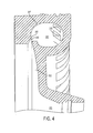
- FIG. 4 is a detailed cross sectional perspective view of a stationary member of a rotating machine, according to an exemplary embodiment.
- FIG. 5 is a cross sectional view of a static member and rotating member arranged to transfer fluid, according to an exemplary embodiment.
- Exemplary embodiments of the present invention provide a free-surface, circumferentially continuous film of liquid transferring from a rotating member to a stationary member within a rotating machine.
- Liquid is transferred from an interior of the rotating member to the inclined surface of the slinger portion through slots of sufficient radial depth to function as a type of weir.
- the radial position of these slots effectively sets the inside diameter of the fluid held in the rotor by the centrifugal forces.
- the free surface of each weir produces an ambient pressure boundary condition within the interior of the rotating member.
- the shape and alignment of the rotating surface (slinger) and the stationary surfaces (receiver) are selected so that liquid film is transferred without splashing or backflow of liquid mist across the gap between rotating and stationary members.
- the circumferentially uniform surface of the slinger slopes such that the liquid film thins as it moves axially and radially outward on the surface of the slinger.
- the stationary member incorporates a receiver which captures the film of liquid issued from the slinger portion.
- the circumferentially continuous film of liquid is captured in a torus-shaped ring suitably aligned with the slinger portion.
- the receiver performs three major functions including: landing the liquid film on a landing surface to slow the jet velocity and thicken the film; creating a liquid curtain across an annular gap entrance to a hollow torus cavity to prevent backwash of liquid and mist towards free space surrounding the rotating member; and providing overlapping drainage slots spaced uniformly around the circumference of the stationary member to prevent ponding of liquid within the hollow torus cavity.
- the landing surface is a slightly curved surface of revolution with uniform direction of concavity.
- the hollow torus cavity includes, in one embodiment, a more tightly curved toroidal surface as compared to the landing surface with a uniform direction of concavity opposite that of the landing surface.
- the liquid film forms a liquid curtain as it travels or "jumps" from the trailing edge of the landing surface to the leading edge of the toroidal surface.
- Circumferentially overlapping drainage slots formed on the toroidal surface enable drainage of liquid from the hollow torus cavity to a suitable collection sump.
- a suitable thin-wall sleeve or other barrier may be included to separate drained liquid from the free space between rotating and stationary members.
- exemplary embodiments of the present invention include capability for free-surface conveyance of liquid from a rotating member to a stationary member with minimal dispersal of liquid or mist to the free space between members.
- Exemplary embodiments may eliminate the need to convey the fluid through internal passages and transfer tubes where such may be difficult to implement with regard to both the physical placement of passageways and the hydraulic head needed to generate a required flow-rate.
- exemplary embodiments are self-pumping in that sufficient hydraulic head is provided by the rotating member.
- a particular benefit to aerospace electric machinery is the capability to recover oil from enclosed, liquid-immersion-cooled rotor windings of an electric machine without fouling the air gap between rotor and stator with heavy oil mist. Elimination of air gap fouling may result, in one or more embodiments, in a reduction of rotational drag resulting in higher machine efficiency, lower heat load, and lower equipment temperature.
- the system 100 includes a reservoir 101 configured to retain a measure of a working fluid (e.g., oil) suitable for cooling of a rotating machine.
- the system 100 further includes a pumping system and heat exchanger 102 in fluid communication with the reservoir 101.
- the pumping system and heat exchanger 102 may pump working fluid from the reservoir 101 to a rotating member 103 of a rotating machine.
- the rotating member 103 may include a rotor and slinger portion arranged thereon, which are described more fully with reference to FIG. 2 .
- the system 100 also includes a receiver 104 configured to receive a working fluid from the rotating member 103 and transfer the working fluid to the reservoir 101. In this manner, fluid is transferred throughout the system 100 such that heat may be transferred away from the rotating member 103 through the use of the reservoir 101 and pumping system 102.
- the rotating member 103 includes main shaft 201 arranged collinear to a central axis of the rotating member 103.
- the main shaft 201 includes a first end 206 configured to receive a working fluid (e.g., oil) from a pumping system at least somewhat similar to pumping system 102, and a closed second end 202 .
- Second end 202 typically provides mechanical power transmission between rotating member 103 and external machinery.
- the main shaft 201 further includes inner cylindrical wall 204 defining an inner cavity 203.
- a central axis of the inner cylindrical wall 204 is arranged collinear to the central axis of the rotating member 103.
- the inner cavity 203 may be a generally hollow cavity configured to convey working fluid throughout the rotating member 103 from the first end 206 to the second end 202.
- the rotating member 103 further includes outer cylindrical wall 213, first annular wall 212 spanning between the outer cylindrical wall 213 and inner cylindrical wall 204, and a slinger portion 210 also spanning between the outer cylindrical wall 213 and inner cylindrical wall 204.
- the first annular wall 212, slinger portion 210, inner cylindrical wall 204, and outer cylindrical wall 213 define a hollow annular cavity 214 disposed to house componentry 207 and 208 of the rotating member 103.
- a central axis of the hollow annular cavity 214 is arranged collinear to a central axis of the rotating member 103.
- the rotating member 103 includes a plurality of orifices 205 arranged on the inner cylindrical wall 204.
- the plurality of orifices 205 allow working fluid communication between the inner cavity 203 and the hollow annular cavity 214.
- centrifugal forces may push working fluid from the inner cavity 203 through the orifices 205 into the hollow annular cavity 214.
- the rotating member 103 also includes a plurality of radial slots 209 formed on the slinger portion 210. Therefore, as working fluid fills the hollow annular cavity 214 during rotation of the rotating member 103, the working fluid flows past componentry 207 and 208 cooling said componentry and exiting the hollow annular cavity 214 through the plurality of slots 209.
- the plurality of radial slots 209 are of sufficient radial depth such that the working fluid has a free surface as it passes over a weir formed by each slot of the plurality of radial slots 209. Furthermore, the free surface at each weir produces an ambient pressure boundary condition within the rotating member such that working fluid flow is controlled to within a desired rate to provide ample cooling while not over pressurizing the hollow annular cavity 214.
- the slinger portion 210 includes a main surface 211 in communication with the plurality of radial slots 209.
- working fluid is transferred from hollow annular cavity 214 to the main surface 211 of the slinger portion 210 through the plurality of radial slots 209.
- the main surface 211 is inclined in monotonically increasing radial dimension in the axial direction from the rotating member towards the stationary member somewhat similar to a bell or bell-like shape. Therefore, as the rotating member 103 rotates and fluid is transferred to the main surface 211, a continuous film of working fluid is produced at an outer edge of the main surface 211 with both tangential and radial velocity components. As this continuous film flows outwards, it may be transferred to a stationary member or receiver of a rotating machine. Such is illustrated and described with reference to FIGS. 3-5 .
- the stationary member 104 includes a main surface 311 and a landing surface 312 arranged around the main surface 311.
- the main surface may be configured to align to a slinger portion of a rotating member (illustrated in FIG. 5 ).
- the landing surface 312 may be a uniformly concave surface surrounding the main surface 311 and configured to slow a velocity of a continuous film of working fluid flowing thereon which has been received from a slinger portion of a rotating member.
- the stationary member 104 may further include toroidal surface 317 defining hollow torus cavity 313.
- a leading edge 315 of the toroidal surface 317 defines annular gap 314 which allows a working fluid to flow into the hollow torus cavity 313 forming an oil curtain spanning the entire annular gap 314.
- a plurality of drainage slots 316 formed on the toroidal surface 317 allows a working fluid to flow out of the hollow torus cavity for drainage into a working fluid reservoir, for example, reservoir 101 of FIG. 1 .
- the central axes of the leading edge 315, the toroidal surface 317, the annular gap 314, and the hollow torus cavity 313 are all collinear.
- FIG. 5 a cross sectional view of a stationary member and rotating member arranged to transfer fluid are illustrated, according to an exemplary embodiment.
- the stationary member 104 surrounds the rotating member 103 such that working fluid may travel from the slinger portion 210 to the landing surface 312 of the stationary portion 104. Thereafter, working fluid may flow across the landing surface 312, across annular gap 314, into hollow torus cavity 313, and through slots 316 into drainage cavity 501 formed of free space between the stationary member 104, inner cylindrical wall 510, outer cylindrical wall 511 and componentry 512. Thereafter, working fluid may flow through drainage orifice 502 into sump 503, which may further drain through orifice 504 into a suitable reservoir.
Landscapes
- Engineering & Computer Science (AREA)
- Power Engineering (AREA)
- Motor Or Generator Cooling System (AREA)
- Motor Or Generator Frames (AREA)
Abstract
A free-surface liquid transfer apparatus for rotating machinery includes a stationary member (104). The stationary member includes a main surface (311) configured to align to a rotating member (103), a landing surface (312) arranged around the main surface configured to receive and slow a continuous film of working fluid transferred from the rotating member, an annular gap (314) arranged around the landing surface, and a hollow torus cavity (313) arranged proximate the annular gap configured to receive the slowed continuous film of working fluid transmitted through the annular gap.
Description
- The present invention is generally related to liquid cooling of rotating machinery, and more particularly, exemplary embodiments of the present invention are directed to free-surface liquid transfer between rotating and stationary members of rotating machinery.
- Liquid that circulates between stationary and rotating members of rotating machinery requires liquid transfer devices for liquid delivery to, and subsequent recovery from, the rotating member. A transfer tube is typically employed at the rotating member shaft centerline for liquid delivery. However, many machine designs preclude the use of another transfer tube for liquid recovery. Additionally, liquid within the rotating member shaft can exert relatively high static pressure induced by centrifugal force.
- According to one aspect of the present invention, a free-surface liquid transfer apparatus for rotating machinery includes a stationary member. The stationary member includes a main surface configured to receive a rotating member, a landing surface arranged around the main surface configured to receive and slow a continuous film of working fluid transferred from the rotating member, an annular gap arranged around the landing surface, and a hollow torus cavity arranged proximate the annular gap configured to receive the slowed continuous film of working fluid transmitted through the annular gap.
- According to another aspect of the present invention, a cooling system for rotating machinery includes a stationary member, a reservoir configured to store a working fluid received from the stationary member, and a pumping system configured to remove working fluid from the reservoir. According to the exemplary embodiment, the stationary member includes a main surface configured to receive a rotating member, a landing surface arranged around the main surface configured to receive and slow a continuous film of working fluid transferred from the rotating member, an annular gap arranged around the landing surface, and a hollow torus cavity arranged proximate the annular gap configured to receive the slowed continuous film of working fluid transmitted through the annular gap.
- The subject matter which is regarded as the invention is particularly pointed out and distinctly claimed in the claims at the conclusion of the specification. The foregoing and other features, and advantages of the invention are apparent from the following detailed description taken in conjunction with the accompanying drawings in which:
-
FIG. 1 is a diagram of a liquid cooling system for rotating machinery, according to an exemplary embodiment; -
FIG. 2 is an isometric view of a rotating member of a rotating machine, according to an exemplary embodiment; -
FIG. 3 is a cross sectional perspective view of a stationary member of a rotating machine, according to an exemplary embodiment; -
FIG. 4 is a detailed cross sectional perspective view of a stationary member of a rotating machine, according to an exemplary embodiment; and -
FIG. 5 is a cross sectional view of a static member and rotating member arranged to transfer fluid, according to an exemplary embodiment. - Exemplary embodiments of the present invention provide a free-surface, circumferentially continuous film of liquid transferring from a rotating member to a stationary member within a rotating machine. Liquid is transferred from an interior of the rotating member to the inclined surface of the slinger portion through slots of sufficient radial depth to function as a type of weir. The radial position of these slots effectively sets the inside diameter of the fluid held in the rotor by the centrifugal forces. The free surface of each weir produces an ambient pressure boundary condition within the interior of the rotating member. The shape and alignment of the rotating surface (slinger) and the stationary surfaces (receiver) are selected so that liquid film is transferred without splashing or backflow of liquid mist across the gap between rotating and stationary members. The circumferentially uniform surface of the slinger slopes such that the liquid film thins as it moves axially and radially outward on the surface of the slinger.
- The stationary member, in turn, incorporates a receiver which captures the film of liquid issued from the slinger portion. The circumferentially continuous film of liquid is captured in a torus-shaped ring suitably aligned with the slinger portion. In one embodiment, the receiver performs three major functions including: landing the liquid film on a landing surface to slow the jet velocity and thicken the film; creating a liquid curtain across an annular gap entrance to a hollow torus cavity to prevent backwash of liquid and mist towards free space surrounding the rotating member; and providing overlapping drainage slots spaced uniformly around the circumference of the stationary member to prevent ponding of liquid within the hollow torus cavity. In one embodiment, the landing surface is a slightly curved surface of revolution with uniform direction of concavity.
- The hollow torus cavity includes, in one embodiment, a more tightly curved toroidal surface as compared to the landing surface with a uniform direction of concavity opposite that of the landing surface. The liquid film forms a liquid curtain as it travels or "jumps" from the trailing edge of the landing surface to the leading edge of the toroidal surface. Circumferentially overlapping drainage slots formed on the toroidal surface enable drainage of liquid from the hollow torus cavity to a suitable collection sump. Depending on machine configuration, a suitable thin-wall sleeve or other barrier may be included to separate drained liquid from the free space between rotating and stationary members.
- As disclosed herein, technical effects and benefits of exemplary embodiments of the present invention include capability for free-surface conveyance of liquid from a rotating member to a stationary member with minimal dispersal of liquid or mist to the free space between members. Exemplary embodiments may eliminate the need to convey the fluid through internal passages and transfer tubes where such may be difficult to implement with regard to both the physical placement of passageways and the hydraulic head needed to generate a required flow-rate. Further, exemplary embodiments are self-pumping in that sufficient hydraulic head is provided by the rotating member. Moreover, a particular benefit to aerospace electric machinery is the capability to recover oil from enclosed, liquid-immersion-cooled rotor windings of an electric machine without fouling the air gap between rotor and stator with heavy oil mist. Elimination of air gap fouling may result, in one or more embodiments, in a reduction of rotational drag resulting in higher machine efficiency, lower heat load, and lower equipment temperature.
- Turning now to
FIG. 1 , a diagram of a liquid cooling system for rotating machinery is illustrated, according to an exemplary embodiment. Thesystem 100 includes areservoir 101 configured to retain a measure of a working fluid (e.g., oil) suitable for cooling of a rotating machine. Thesystem 100 further includes a pumping system andheat exchanger 102 in fluid communication with thereservoir 101. The pumping system andheat exchanger 102 may pump working fluid from thereservoir 101 to a rotatingmember 103 of a rotating machine. As described above, the rotatingmember 103 may include a rotor and slinger portion arranged thereon, which are described more fully with reference toFIG. 2 . - As further illustrated, the
system 100 also includes areceiver 104 configured to receive a working fluid from the rotatingmember 103 and transfer the working fluid to thereservoir 101. In this manner, fluid is transferred throughout thesystem 100 such that heat may be transferred away from the rotatingmember 103 through the use of thereservoir 101 andpumping system 102. - Turning now to
FIG. 2 , an isometric view of a rotatingmember 103 of a rotating machine is illustrated, according to an exemplary embodiment. The rotatingmember 103 includesmain shaft 201 arranged collinear to a central axis of the rotatingmember 103. Themain shaft 201 includes afirst end 206 configured to receive a working fluid (e.g., oil) from a pumping system at least somewhat similar topumping system 102, and a closedsecond end 202 .Second end 202 typically provides mechanical power transmission between rotatingmember 103 and external machinery. Themain shaft 201 further includes innercylindrical wall 204 defining aninner cavity 203. A central axis of the innercylindrical wall 204 is arranged collinear to the central axis of the rotatingmember 103. Theinner cavity 203 may be a generally hollow cavity configured to convey working fluid throughout the rotatingmember 103 from thefirst end 206 to thesecond end 202. - As further illustrated, the rotating
member 103 further includes outercylindrical wall 213, firstannular wall 212 spanning between the outercylindrical wall 213 and innercylindrical wall 204, and aslinger portion 210 also spanning between the outercylindrical wall 213 and innercylindrical wall 204. As shown, the firstannular wall 212,slinger portion 210, innercylindrical wall 204, and outercylindrical wall 213 define a hollowannular cavity 214 disposed tohouse componentry member 103. Furthermore, a central axis of the hollowannular cavity 214 is arranged collinear to a central axis of the rotatingmember 103. - As further illustrated, the rotating
member 103 includes a plurality oforifices 205 arranged on the innercylindrical wall 204. The plurality oforifices 205 allow working fluid communication between theinner cavity 203 and the hollowannular cavity 214. For example, as the rotatingmember 103 is configured to rotate, centrifugal forces may push working fluid from theinner cavity 203 through theorifices 205 into the hollowannular cavity 214. - As further illustrated, the rotating
member 103 also includes a plurality ofradial slots 209 formed on theslinger portion 210. Therefore, as working fluid fills the hollowannular cavity 214 during rotation of the rotatingmember 103, the working fluid flows pastcomponentry annular cavity 214 through the plurality ofslots 209. According to one exemplary embodiment, the plurality ofradial slots 209 are of sufficient radial depth such that the working fluid has a free surface as it passes over a weir formed by each slot of the plurality ofradial slots 209. Furthermore, the free surface at each weir produces an ambient pressure boundary condition within the rotating member such that working fluid flow is controlled to within a desired rate to provide ample cooling while not over pressurizing the hollowannular cavity 214. - As further illustrated, the
slinger portion 210 includes amain surface 211 in communication with the plurality ofradial slots 209. Thus, working fluid is transferred from hollowannular cavity 214 to themain surface 211 of theslinger portion 210 through the plurality ofradial slots 209. Furthermore, themain surface 211 is inclined in monotonically increasing radial dimension in the axial direction from the rotating member towards the stationary member somewhat similar to a bell or bell-like shape. Therefore, as the rotatingmember 103 rotates and fluid is transferred to themain surface 211, a continuous film of working fluid is produced at an outer edge of themain surface 211 with both tangential and radial velocity components. As this continuous film flows outwards, it may be transferred to a stationary member or receiver of a rotating machine. Such is illustrated and described with reference toFIGS. 3-5 . - Turning now to
FIGS. 3-4 , a cross sectional perspective view and a detailed cross-sectional perspective view of a stationary member of a rotating machine are illustrated, according to an exemplary embodiment. As shown inFIG. 3 , thestationary member 104 includes amain surface 311 and alanding surface 312 arranged around themain surface 311. The main surface may be configured to align to a slinger portion of a rotating member (illustrated inFIG. 5 ). Thelanding surface 312 may be a uniformly concave surface surrounding themain surface 311 and configured to slow a velocity of a continuous film of working fluid flowing thereon which has been received from a slinger portion of a rotating member. - As shown in
FIG. 4 , thestationary member 104 may further includetoroidal surface 317 defininghollow torus cavity 313. Aleading edge 315 of thetoroidal surface 317 definesannular gap 314 which allows a working fluid to flow into thehollow torus cavity 313 forming an oil curtain spanning the entireannular gap 314. Furthermore, a plurality ofdrainage slots 316 formed on thetoroidal surface 317 allows a working fluid to flow out of the hollow torus cavity for drainage into a working fluid reservoir, for example,reservoir 101 ofFIG. 1 . As illustrated, the central axes of theleading edge 315, thetoroidal surface 317, theannular gap 314, and thehollow torus cavity 313 are all collinear. - Turning now to
FIG. 5 , a cross sectional view of a stationary member and rotating member arranged to transfer fluid are illustrated, according to an exemplary embodiment. As shown, thestationary member 104 surrounds the rotatingmember 103 such that working fluid may travel from theslinger portion 210 to thelanding surface 312 of thestationary portion 104. Thereafter, working fluid may flow across thelanding surface 312, acrossannular gap 314, intohollow torus cavity 313, and throughslots 316 intodrainage cavity 501 formed of free space between thestationary member 104, innercylindrical wall 510, outercylindrical wall 511 andcomponentry 512. Thereafter, working fluid may flow throughdrainage orifice 502 intosump 503, which may further drain throughorifice 504 into a suitable reservoir. - While the invention has been described in detail in connection with only a limited number of embodiments, it should be readily understood that the invention is not limited to such disclosed embodiments. Rather, the invention can be modified to incorporate any number of variations, alterations, substitutions or equivalent arrangements not heretofore described, but which are commensurate with the scope of the invention, which is defined by the claims. Additionally, while various embodiments of the invention have been described, it is to be understood that aspects of the invention may include only some of the described embodiments. Accordingly, the invention is not to be seen as limited by the foregoing description, but is only limited by the scope of the appended claims.
Claims (12)
- A free-surface liquid transfer apparatus for rotating machinery, comprising:a stationary member (104), wherein the stationary member comprises:an annular main surface (311);a landing surface (312) arranged around the main surface and configured to receive and slow a continuous film of working fluid transferred to the landing surface;an annular gap (314) arranged around the landing surface; anda hollow torus cavity (313) arranged proximate the annular gap and configured to receive the slowed continuous film of working fluid transmitted through the annular gap.
- The apparatus of claim 1, wherein the stationary member further comprises a plurality of drainage slots (316) arranged about the hollow torus cavity configured to drain working fluid from the hollow torus cavity.
- The apparatus of claim 2, wherein the plurality of drainage slots are circumferentially overlapping.
- The apparatus of any preceding claim, wherein the landing surface is a curved surface of revolution with uniform direction of concavity.
- The apparatus of any preceding claim, wherein a direction of concavity of the hollow torus cavity is opposite the direction of concavity of the landing surface.
- The apparatus of any preceding claim, further comprising a rotating member (103), the main surface being aligned with the rotating member and the rotating member being positioned for transferring the continuous film of working fluid to the landing surface.
- The apparatus of claim 6, wherein the rotating member comprises:a main shaft (201) defining a hollow inner cavity (203);an outer cylindrical wall (213) defining a hollow annular cavity (214) in fluid communication with the hollow inner cavity through a plurality of orifices (205) formed on the main shaft; anda slinger formation (210) in fluid communication with the hollow annular cavity through a plurality of radial slots (209) formed through the slinger formation;wherein a central axis of the main shaft, a central axis of the hollow annular cavity, and a central axis of the slinger formation are collinear, and
wherein the slinger formation is configured to transmit working fluid received through the plurality of radial slots outward as a continuous film having both tangential and radial velocity components. - The apparatus of claim 7, wherein the rotating member further comprises a plurality of rotating machine componentry (207,208) arranged inside the hollow annular cavity.
- The apparatus of claim 7 or 8, wherein each radial slot of the plurality of radial slots forms a weir, and wherein a radial depth of the plurality of radial slots is constant and configured to provide a free-surface for working fluid flow over each weir.
- The apparatus of claim 7, 8 or 9, wherein the slinger formation comprises:a main surface (211) inclined monotonically in a radial direction.
- The apparatus of claim 10, wherein the inclined main surface (211) is circumferentially continuous about the central axis of the rotating member.
- A cooling system (100) for rotating machinery, comprising:the free-surface liquid transfer apparatus of any preceding claim;a reservoir (101) configured to store a working fluid received from the stationary member; anda pumping system (102) configured to remove working fluid from the reservoir.
Applications Claiming Priority (1)
| Application Number | Priority Date | Filing Date | Title |
|---|---|---|---|
| US13/279,230 US9300190B2 (en) | 2011-10-21 | 2011-10-21 | Free-surface liquid capture device for rotating machinery |
Publications (1)
| Publication Number | Publication Date |
|---|---|
| EP2584675A2 true EP2584675A2 (en) | 2013-04-24 |
Family
ID=46724272
Family Applications (1)
| Application Number | Title | Priority Date | Filing Date |
|---|---|---|---|
| EP12181243.2A Withdrawn EP2584675A2 (en) | 2011-10-21 | 2012-08-21 | Free-surface liquid capture device for rotating machinery |
Country Status (2)
| Country | Link |
|---|---|
| US (1) | US9300190B2 (en) |
| EP (1) | EP2584675A2 (en) |
Cited By (3)
| Publication number | Priority date | Publication date | Assignee | Title |
|---|---|---|---|---|
| DE102013226661A1 (en) * | 2013-12-19 | 2015-06-25 | Volkswagen Aktiengesellschaft | Hybrid drive module with an electric machine |
| CN110021727A (en) * | 2018-01-10 | 2019-07-16 | 宁德时代新能源科技股份有限公司 | One-way vent valve, top cover assembly of secondary battery, and secondary battery |
| WO2022231496A1 (en) | 2021-04-28 | 2022-11-03 | Scania Cv Ab | An electric rotating machine with means for draining cooling fluid from a rotor compartment |
Families Citing this family (3)
| Publication number | Priority date | Publication date | Assignee | Title |
|---|---|---|---|---|
| DE102012203697A1 (en) * | 2012-03-08 | 2013-09-12 | Siemens Aktiengesellschaft | Electric machine with a rotor for cooling the electric machine |
| JP6398748B2 (en) * | 2015-01-28 | 2018-10-03 | 株式会社デンソー | Rotating electric machine |
| DE102017220989A1 (en) * | 2017-11-23 | 2018-11-29 | Zf Friedrichshafen Ag | Oil guide assembly for a transmission housing |
Family Cites Families (23)
| Publication number | Priority date | Publication date | Assignee | Title |
|---|---|---|---|---|
| US2557075A (en) * | 1948-07-26 | 1951-06-19 | James V Caputo | Vertical-shaft dynamoelectric machine |
| US3272476A (en) * | 1960-08-30 | 1966-09-13 | Sundstrand Corp | Engine starter |
| US3746349A (en) * | 1970-08-26 | 1973-07-17 | F Robson | Mechanical seals and or thrust bearings |
| DE2711847C2 (en) * | 1977-03-18 | 1979-03-22 | Kernforschungsanlage Juelich Gmbh, 5170 Juelich | X-ray tube |
| US5018181A (en) * | 1987-06-02 | 1991-05-21 | Coriolis Corporation | Liquid cooled rotating anodes |
| US5077781A (en) * | 1990-01-30 | 1991-12-31 | Iversen Arthur H | Rotating shaft assembly for x-ray tubes |
| US4992023A (en) * | 1990-07-05 | 1991-02-12 | General Motors Corporation | Vehicle water pump with improved slinger |
| JP3289698B2 (en) | 1998-11-25 | 2002-06-10 | 株式会社日立製作所 | Rotating electric machine |
| US6685447B2 (en) * | 2002-01-25 | 2004-02-03 | Hamilton Sundstrand | Liquid cooled integrated rotordynamic motor/generator station with sealed power electronic controls |
| JP3836855B2 (en) * | 2004-07-15 | 2006-10-25 | 株式会社リガク | Rotating anti-cathode X-ray tube and X-ray generator |
| US7475914B2 (en) * | 2004-09-14 | 2009-01-13 | Pospisil Mark G | Rotary union for directing a heat exchange fluid |
| US7342332B2 (en) | 2004-09-22 | 2008-03-11 | Hamilton Sundstrand Corporation | Air bearing and motor cooling |
| US7575421B2 (en) | 2004-09-22 | 2009-08-18 | Hamilton Sundstrand Corporation | Integral motor cooling and compressor inlet |
| US7644792B2 (en) | 2006-01-06 | 2010-01-12 | Hamilton Sundstrand | Motor cooling system |
| JP5026010B2 (en) * | 2006-07-19 | 2012-09-12 | デンヨー株式会社 | Cooling fan for rotating equipment |
| US7692553B2 (en) * | 2006-07-21 | 2010-04-06 | Deublin Company | Leak detecting system for rotating union |
| US7732953B2 (en) | 2007-06-12 | 2010-06-08 | Hamilton Sundstrand Corporation | Electric motor cooling |
| KR100999687B1 (en) | 2008-12-16 | 2010-12-08 | 두산중공업 주식회사 | Superconducting rotating machine with rotor with cooling device |
| US7994668B2 (en) * | 2009-05-18 | 2011-08-09 | General Electric Company | Cooling system for rotating machine |
| US8009805B2 (en) * | 2009-06-09 | 2011-08-30 | General Electric Company | Rotating union for a liquid cooled rotating X-ray target |
| KR101062599B1 (en) * | 2009-10-21 | 2011-09-06 | 두산중공업 주식회사 | Cooling flow path structure of superconducting rotary machine |
| JP5498773B2 (en) * | 2009-12-24 | 2014-05-21 | 株式会社日本自動車部品総合研究所 | Rotating electric machine |
| US8692425B2 (en) * | 2011-05-10 | 2014-04-08 | Remy Technologies, Llc | Cooling combinations for electric machines |
-
2011
- 2011-10-21 US US13/279,230 patent/US9300190B2/en active Active
-
2012
- 2012-08-21 EP EP12181243.2A patent/EP2584675A2/en not_active Withdrawn
Non-Patent Citations (1)
| Title |
|---|
| None |
Cited By (6)
| Publication number | Priority date | Publication date | Assignee | Title |
|---|---|---|---|---|
| DE102013226661A1 (en) * | 2013-12-19 | 2015-06-25 | Volkswagen Aktiengesellschaft | Hybrid drive module with an electric machine |
| CN110021727A (en) * | 2018-01-10 | 2019-07-16 | 宁德时代新能源科技股份有限公司 | One-way vent valve, top cover assembly of secondary battery, and secondary battery |
| CN110021727B (en) * | 2018-01-10 | 2021-09-14 | 宁德时代新能源科技股份有限公司 | One-way vent valve, secondary battery's top cap subassembly and secondary battery |
| WO2022231496A1 (en) | 2021-04-28 | 2022-11-03 | Scania Cv Ab | An electric rotating machine with means for draining cooling fluid from a rotor compartment |
| EP4331096A4 (en) * | 2021-04-28 | 2025-04-02 | Scania CV AB | ROTATING ELECTRIC MACHINE PROVIDED WITH MEANS FOR DRAINING COOLING FLUID FROM A ROTOR COMPARTMENT |
| US12614952B2 (en) | 2021-04-28 | 2026-04-28 | Traton Ab | Electric rotating machine with means for draining cooling fluid from a rotor compartment |
Also Published As
| Publication number | Publication date |
|---|---|
| US20130098585A1 (en) | 2013-04-25 |
| US9300190B2 (en) | 2016-03-29 |
Similar Documents
| Publication | Publication Date | Title |
|---|---|---|
| US9300190B2 (en) | Free-surface liquid capture device for rotating machinery | |
| EP2541737B1 (en) | Electrical machine | |
| CN104105895B (en) | Rolling bearing facilities | |
| KR101757285B1 (en) | Rotating directional coolant spray for electric machine | |
| JP6525193B2 (en) | Planetary transmission provided with a lubrication system | |
| JP6765973B2 (en) | Cooling system for magnetic axial bearings | |
| US20160344263A1 (en) | Electric machine | |
| JP6312346B2 (en) | Journal bearing, rotating machine | |
| CN107888024B (en) | Cooling system and motor | |
| CN107437859A (en) | Rotor for motor | |
| EP2712805A1 (en) | System and method for cooling a hover-capable aircraft transmission | |
| EP3739727B1 (en) | Fluid cooling of grease-packed bearings | |
| EP3032713B1 (en) | Electrical machine with reduced windage | |
| KR101853983B1 (en) | Neck seal for a rolling mill oil film bearing with spaced impellers for propelling oil coming out from the bearing's sleeve and bushing | |
| JP2003526305A (en) | Improved bearing insulation | |
| US8506240B2 (en) | Free-surface liquid transfer device for rotating machinery | |
| RU2544245C2 (en) | Self-pumping hydrostatic bearing | |
| CA3215538A1 (en) | Tangential jet cooling for electric motors | |
| RU2537630C2 (en) | Drain with venturi tube for rolling mills with self-pumping bearing | |
| JP2007325358A (en) | Motor | |
| CN105822861A (en) | Multi-channel rotary joint applicable to simultaneous transmission of multiple media | |
| CN215817826U (en) | Canned motor pump and motor thereof | |
| EP3070307B1 (en) | Deaerator shaft with attachment surfaces | |
| EP4712313A1 (en) | Electric drive unit with improved rotor cooling system | |
| EP3070373B1 (en) | Deaerator gear with attachment surfaces |
Legal Events
| Date | Code | Title | Description |
|---|---|---|---|
| PUAI | Public reference made under article 153(3) epc to a published international application that has entered the european phase |
Free format text: ORIGINAL CODE: 0009012 |
|
| AK | Designated contracting states |
Kind code of ref document: A2 Designated state(s): AL AT BE BG CH CY CZ DE DK EE ES FI FR GB GR HR HU IE IS IT LI LT LU LV MC MK MT NL NO PL PT RO RS SE SI SK SM TR |
|
| AX | Request for extension of the european patent |
Extension state: BA ME |
|
| STAA | Information on the status of an ep patent application or granted ep patent |
Free format text: STATUS: THE APPLICATION HAS BEEN WITHDRAWN |
|
| 18W | Application withdrawn |
Effective date: 20131218 |