EP2584234A1 - Electromagnetic on-off valve - Google Patents
Electromagnetic on-off valve Download PDFInfo
- Publication number
- EP2584234A1 EP2584234A1 EP11795365.3A EP11795365A EP2584234A1 EP 2584234 A1 EP2584234 A1 EP 2584234A1 EP 11795365 A EP11795365 A EP 11795365A EP 2584234 A1 EP2584234 A1 EP 2584234A1
- Authority
- EP
- European Patent Office
- Prior art keywords
- valve body
- pilot
- plunger
- main
- main valve
- Prior art date
- Legal status (The legal status is an assumption and is not a legal conclusion. Google has not performed a legal analysis and makes no representation as to the accuracy of the status listed.)
- Withdrawn
Links
Images





Classifications
-
- F—MECHANICAL ENGINEERING; LIGHTING; HEATING; WEAPONS; BLASTING
- F16—ENGINEERING ELEMENTS AND UNITS; GENERAL MEASURES FOR PRODUCING AND MAINTAINING EFFECTIVE FUNCTIONING OF MACHINES OR INSTALLATIONS; THERMAL INSULATION IN GENERAL
- F16K—VALVES; TAPS; COCKS; ACTUATING-FLOATS; DEVICES FOR VENTING OR AERATING
- F16K31/00—Actuating devices; Operating means; Releasing devices
- F16K31/12—Actuating devices; Operating means; Releasing devices actuated by fluid
- F16K31/36—Actuating devices; Operating means; Releasing devices actuated by fluid in which fluid from the circuit is constantly supplied to the fluid motor
- F16K31/40—Actuating devices; Operating means; Releasing devices actuated by fluid in which fluid from the circuit is constantly supplied to the fluid motor with electrically-actuated member in the discharge of the motor
-
- F—MECHANICAL ENGINEERING; LIGHTING; HEATING; WEAPONS; BLASTING
- F16—ENGINEERING ELEMENTS AND UNITS; GENERAL MEASURES FOR PRODUCING AND MAINTAINING EFFECTIVE FUNCTIONING OF MACHINES OR INSTALLATIONS; THERMAL INSULATION IN GENERAL
- F16K—VALVES; TAPS; COCKS; ACTUATING-FLOATS; DEVICES FOR VENTING OR AERATING
- F16K31/00—Actuating devices; Operating means; Releasing devices
- F16K31/12—Actuating devices; Operating means; Releasing devices actuated by fluid
- F16K31/42—Actuating devices; Operating means; Releasing devices actuated by fluid by means of electrically-actuated members in the supply or discharge conduits of the fluid motor
-
- F—MECHANICAL ENGINEERING; LIGHTING; HEATING; WEAPONS; BLASTING
- F16—ENGINEERING ELEMENTS AND UNITS; GENERAL MEASURES FOR PRODUCING AND MAINTAINING EFFECTIVE FUNCTIONING OF MACHINES OR INSTALLATIONS; THERMAL INSULATION IN GENERAL
- F16K—VALVES; TAPS; COCKS; ACTUATING-FLOATS; DEVICES FOR VENTING OR AERATING
- F16K31/00—Actuating devices; Operating means; Releasing devices
- F16K31/02—Actuating devices; Operating means; Releasing devices electric; magnetic
- F16K31/06—Actuating devices; Operating means; Releasing devices electric; magnetic using a magnet, e.g. diaphragm valves, cutting off by means of a liquid
-
- F—MECHANICAL ENGINEERING; LIGHTING; HEATING; WEAPONS; BLASTING
- F16—ENGINEERING ELEMENTS AND UNITS; GENERAL MEASURES FOR PRODUCING AND MAINTAINING EFFECTIVE FUNCTIONING OF MACHINES OR INSTALLATIONS; THERMAL INSULATION IN GENERAL
- F16K—VALVES; TAPS; COCKS; ACTUATING-FLOATS; DEVICES FOR VENTING OR AERATING
- F16K31/00—Actuating devices; Operating means; Releasing devices
- F16K31/02—Actuating devices; Operating means; Releasing devices electric; magnetic
- F16K31/06—Actuating devices; Operating means; Releasing devices electric; magnetic using a magnet, e.g. diaphragm valves, cutting off by means of a liquid
- F16K31/0644—One-way valve
- F16K31/0655—Lift valves
-
- F—MECHANICAL ENGINEERING; LIGHTING; HEATING; WEAPONS; BLASTING
- F16—ENGINEERING ELEMENTS AND UNITS; GENERAL MEASURES FOR PRODUCING AND MAINTAINING EFFECTIVE FUNCTIONING OF MACHINES OR INSTALLATIONS; THERMAL INSULATION IN GENERAL
- F16K—VALVES; TAPS; COCKS; ACTUATING-FLOATS; DEVICES FOR VENTING OR AERATING
- F16K39/00—Devices for relieving the pressure on the sealing faces
- F16K39/02—Devices for relieving the pressure on the sealing faces for lift valves
- F16K39/024—Devices for relieving the pressure on the sealing faces for lift valves using an auxiliary valve on the main valve
-
- H—ELECTRICITY
- H01—ELECTRIC ELEMENTS
- H01M—PROCESSES OR MEANS, e.g. BATTERIES, FOR THE DIRECT CONVERSION OF CHEMICAL ENERGY INTO ELECTRICAL ENERGY
- H01M8/00—Fuel cells; Manufacture thereof
- H01M8/04—Auxiliary arrangements, e.g. for control of pressure or for circulation of fluids
-
- H—ELECTRICITY
- H01—ELECTRIC ELEMENTS
- H01M—PROCESSES OR MEANS, e.g. BATTERIES, FOR THE DIRECT CONVERSION OF CHEMICAL ENERGY INTO ELECTRICAL ENERGY
- H01M8/00—Fuel cells; Manufacture thereof
- H01M8/04—Auxiliary arrangements, e.g. for control of pressure or for circulation of fluids
- H01M8/04082—Arrangements for control of reactant parameters, e.g. pressure or concentration
- H01M8/04201—Reactant storage and supply, e.g. means for feeding, pipes
-
- Y—GENERAL TAGGING OF NEW TECHNOLOGICAL DEVELOPMENTS; GENERAL TAGGING OF CROSS-SECTIONAL TECHNOLOGIES SPANNING OVER SEVERAL SECTIONS OF THE IPC; TECHNICAL SUBJECTS COVERED BY FORMER USPC CROSS-REFERENCE ART COLLECTIONS [XRACs] AND DIGESTS
- Y02—TECHNOLOGIES OR APPLICATIONS FOR MITIGATION OR ADAPTATION AGAINST CLIMATE CHANGE
- Y02E—REDUCTION OF GREENHOUSE GAS [GHG] EMISSIONS, RELATED TO ENERGY GENERATION, TRANSMISSION OR DISTRIBUTION
- Y02E60/00—Enabling technologies; Technologies with a potential or indirect contribution to GHG emissions mitigation
- Y02E60/30—Hydrogen technology
- Y02E60/50—Fuel cells
Definitions
- the present invention relates to a solenoid on-off valve capable of switching between the discharge and non-discharge of a gas from a tank by an electromagnetic solenoid and filling the tank with the gas.
- a valve block is provided on an opening of a tank, and a discharging channel and filling channel, each of which connects the inside and outside of the tank, are formed on the valve block.
- the discharging channel is a channel through which a gas in the tank is discharged
- the filling channel is a channel through which the gas is filled in the tank.
- the valve block generally includes a solenoid on-off valve and a check valve.
- the solenoid on-off valve has a function of opening and closing the discharging channel in accordance with the existence or non-existence of a current flowing therethrough
- the check valve has a function of allowing the flow of the gas from the outside of the tank to the filling channel and blocking the opposite flow.
- valve block configured as above includes two systems that are a discharging system and a filling system, the overall size thereof becomes large. Therefore, it is preferable that one system perform both discharging and filling operations. To realize this, a valve having both the function of the solenoid on-off valve and the function of the check valve is required.
- a pilot solenoid valve described in, for example, PTL 1 or PTL 2.
- the pilot solenoid valve (hereinafter simply referred to as "solenoid valve") described in each of PTLs 1 and 2 includes a housing on which a communication channel is formed.
- a main valve body, a pilot valve body, and a plunger are included in the housing.
- the main valve body is seated on a main valve seat portion formed on the housing to close the communication channel.
- the main valve body includes an orifice hole connected to the communication channel, and the pilot valve body is inserted into the main valve body.
- the pilot valve body is seated on a pilot valve seat portion formed on the main valve body to close the orifice hole.
- the plunger is coupled to the main valve body and the pilot valve body by a pilot pin penetrating the main valve body and the pilot valve body.
- the plunger moves by driving an electromagnetic solenoid provided on an outer periphery of the plunger.
- the pilot valve body and the main valve body move in accordance with the movement of the plunger by the pilot pin.
- the pilot valve body and the main valve body are separated from the respective seat portions in this order.
- the orifice hole opens first, and the communication channel then opens. When the communication channel opens, a hydrogen gas is discharged from a hydrogen tank to be supplied to a fuel cell.
- the pilot valve body In the solenoid valve, the pilot valve body is being biased by a spring.
- the pilot valve body When the electromagnetic solenoid is not operating, the pilot valve body is pressed against the pilot seat portion by a main valve spring to close the orifice hole.
- the main valve body is pressed against the main valve seat portion by the main valve spring through the pilot valve body to close the communication channel.
- through holes are respectively formed on the main valve body and the pilot valve body.
- these valve bodies and the plunger are coupled to one another.
- Center lines of these two through holes are positioned so as to be displaced from each other in a direction perpendicular to a direction in which the pin is inserted.
- the main valve body when filling the hydrogen tank with the hydrogen gas, the main valve body is lifted up with the pilot valve body seated on the pilot seat portion.
- the solenoid valve described in PTL 1 when the pilot valve body contacts the pilot pin and is not lifted up any more, the pilot seat portion is sandwiched between the pilot valve body and the main valve body which is being lifted up by the pressure of the hydrogen gas, and receives from the pilot valve body a force corresponding to the pressing force. As a result, problems, such as the deterioration of the pilot seat portion, occur.
- the solenoid valve described in PTL 2 when the main valve body is pushed up, the main valve body contacts the pilot pin before the pilot valve body contacts the pilot pin, and the pilot valve body is pressed against the pilot seat portion by a pilot valve spring. With this, only a pressing force corresponding to a press force of the pilot valve spring is applied to the pilot seat portion. Thus, the pressing force that the pilot seat portion receives can be reduced. Therefore, the deterioration of the pilot seat portion of, for example, the solenoid valve described in PTL 1 can be reduced.
- the main valve body having been pushed up by the hydrogen gas contacts the pilot pin.
- the hydrogen gas supplied in the filling operation has high pressure.
- An internal pressure of the hydrogen tank is considerably low although it depends on the amount of hydrogen gas used. Therefore, a pressure difference between the inside and outside of the hydrogen tank is large, so that a pushed-up speed of the main valve body immediately after the start of the filling operation, that is, a pushed-up speed of the main valve body when the communication channel starts opening is considerably high.
- the plunger hardly moves and is maintained at an original position. Therefore, the main valve body collides with the pilot pin at a considerably high relative speed, and a strong impact shear force is applied to the pilot pin.
- the pilot pin may be damaged by the impact shear force. Even if the pilot pin has endured the impact shear force, the main valve body is being pressed against the pilot pin by the supplied hydrogen gas in the filling operation, so that a strong static shear force is being applied to the pilot pin supporting the main valve body. Also in the solenoid valve described in PTL 1, at the time of the start of the filling operation and during the filling operation, the pilot valve body seated on the main valve body contacts the pilot pin, so that the pilot pin may be damaged during the filling operation.
- the strength of the pilot pin needs to be increased such that the pilot pin can endure these shear forces.
- the outer diameter of the pilot pin is increased to improve the strength of the pilot valve body, the outer diameter of the solenoid valve becomes large. Therefore, it is preferable that the strong shear force be not applied to the pilot pin.
- an object of the present invention is to provide a solenoid on-off valve configured such that the shear force is not applied to the pilot pin (coupling pin) when the main valve body is pushed and the communication channel (valve port) opens to fill the tank with the gas.
- a solenoid on-off valve of the present invention includes: a housing including a tank space connected to a tank port, a supply and discharge space connected to a supply and discharge port, and a valve port connecting the tank space and the supply and discharge space; a main valve body configured to move between a valve port close position where the main valve body closes the valve port and a valve port open position where the main valve body opens the valve port and including a pilot passage connected to the tank space and the supply and discharge space; a pilot valve body configured to move between a passage close position where the pilot valve body is seated on the main valve body to close the pilot passage and a passage open position where the pilot valve body separates from the main valve body to open the pilot passage; a plunger configured to be movable in an opening direction and cause the pilot valve body and the main valve body to move to the passage open position and the valve port open position in this order when the plunger moves in the opening direction; an electromagnetic solenoid configured to generate an exciting force to cause the plunger to move in the opening direction; a plunger bias
- the plunger moves in the opening direction.
- the pilot valve body first moves to the passage open position, and the pilot passage opens.
- the pressure in the supply and discharge space increases.
- the pressure difference between the tank space and the supply and discharge space decreases, and a force necessary to cause the main valve body to move in the opening direction decreases. Therefore, even if the exciting force of the electromagnetic solenoid is small, the main valve body can be caused to move to the valve port open position in accordance with the movement of the plunger.
- the main valve body moves to the valve port open position and the valve port opens, the tank space and the supply and discharge space are directly connected to each other. With this, the gas can be discharged.
- valve port opens, and the gas in the supply and discharge space can be introduced through the valve port, the tank space, and the tank port to the tank and filled in the tank.
- a valve having an electromagnetic open-close function and a check valve function can be realized by the solenoid on-off valve of the present invention.
- the coupling pin moves relative to one (opponent member) of the two members.
- the coupling pin is about to collide with the opponent member.
- the movement of the main valve body relative to the plunger in the opening direction is stopped. Therefore, the large shear force can be prevented from acting on the coupling pin as in conventional technologies by the collision of the coupling pin with the opponent member. Therefore, the breakage of the coupling pin can be prevented.
- the stiffness of the coupling pin can be reduced, the outer diameter of the coupling pin can be reduced.
- the coupling pin couple the plunger with the pilot valve body; the plunger be provided to be spaced apart from the main valve body in the open direction by a first clearance when the main valve body is located at the valve port close position; the pilot valve body include a plunger insertion hole; the coupling pin be fixed to the plunger, be inserted through the plunger insertion hole so as to be movable, and be provided to be spaced apart from a surface, which forms the plunger insertion hole, in the opening direction by a second clearance when the main valve body is located at the valve port close position; and the second clearance be larger than the first clearance.
- the coupling pin is fixed to the plunger. Therefore, when the main valve body is pushed by the gas to move in the opening direction, the coupling pin moves relative to the main valve body in the closing direction in the plunger insertion hole. Since the plunger and the main valve body are spaced apart from each other only by the first clearance, the main valve body stops moving after it has moved relative to the plunger in the opening direction by the first clearance. Meanwhile, the coupling pin is spaced apart from the surface, which forms the insertion hole, in the opening direction by the second clearance and can move in the closing direction in the insertion hole by the second clearance that is larger than the first clearance. Therefore, even if the main valve body is pushed in the opening direction, the coupling pin does not contact the pilot valve body, and the shear force can be prevented from acting on the coupling pin during the filling operation.
- the pilot valve body and the main valve body be coupled to each other by the pilot pin so as to be movable in accordance with each other, the pilot pin being inserted through the pilot valve body and the main valve body; and the pilot pin be provided so as not to contact the pilot valve body or the main valve body when the main valve body is pushed in the opening direction.
- the pilot pin even if the main valve body is pushed in the opening direction and the pilot pin moves relative to the pilot valve body or the main valve body (target member), the pilot pin does not contact the target member. Therefore, the large shear force can be prevented from acting on the pilot pin by the contact of the pilot pin with the target member. On this account, the breakage of the pilot pin can be prevented. Moreover, since the stiffness of the pilot pin can be reduced, the outer diameter of the pilot pin can be reduced.
- the pilot valve body include a valve main body which is inserted into the main valve body so as to be movable and a pilot valve seat portion which is provided on the valve main body and is seated on the main valve body to close the pilot passage;
- the pilot valve main body be accommodated so as to be spaced apart from the main valve body in the opening direction by a third clearance;
- the coupling pin be provided to be spaced apart from the surface, which forms the plunger insertion hole, in the closing direction by a fourth clearance when the pilot valve main body is located at the passage close position;
- the pilot valve main body further include a main valve insertion hole;
- the pilot pin be fixed to the main valve body, be inserted through the main valve insertion hole so as to be movable, and be provided to be spaced apart from a surface, which forms the main valve insertion hole, in the closing direction by a fifth clearance when the pilot valve body is located at the passage close position; and each of the fourth clearance and the fifth clearance be larger than the third clearance.
- the pilot valve main body moves down toward the main valve body by, for example, the plastic deformation of the pilot valve seat portion, the pilot valve main body contacts the main valve body before it contacts the coupling pin or the pilot pin.
- the pilot valve main body does not move down by the third clearance or more. Therefore, the pilot valve body can be prevented from separating from the main valve body without being seated on the main valve body by the contact of the pilot valve body with the coupling pin or the pilot pin. With this, the leakage from the pilot passage can be prevented.
- the coupling pin couple the plunger with the main valve body; the plunger be provided to be spaced apart from the main valve body by a sixth clearance when the main valve body is located at the valve port close position; the plunger include an insertion hole; the coupling pin be fixed to the main valve body, be inserted through the insertion hole so as to be movable, and be provided to be spaced apart from a surface, which forms the insertion hole, in the closing direction by a seventh clearance when the main valve body is located at the valve port close position; and the seventh clearance be larger than the sixth clearance.
- the coupling pin is fixed to the main valve body. Therefore, when the main valve body is pushed by the gas to move in the opening direction, the coupling pin moves relative to the main valve body in the opening direction in the insertion hole. Since the plunger and the main valve body are spaced apart from each other only by the sixth clearance, the main valve body stops moving after it has moved relative to the plunger in the opening direction by the sixth clearance. Meanwhile, the coupling pin is spaced apart from the surface, which forms the insertion hole, in the opening direction by the seventh clearance or more and can move in the closing direction in the insertion hole by the seventh clearance that is larger than the sixth clearance.
- the plunger include a plunger main body and a cover member;
- the plunger main body include an attachment portion located in the opening direction; a cover member threadedly engage with the attachment portion; a valve space closed by the attachment portion be formed in the cover member; and the pilot valve body contact and be supported by the cover member in the valve space and be provided so as to be movable from a state where the pilot valve body contacts and is supported by the cover member.
- the pilot valve body can be caused to move in accordance with the plunger without the pin. With this, the number of members which may be damaged can be reduced, and the reliability can be further improved.
- the pilot valve body be provided to be spaced apart from an end surface of the attachment portion by an eighth clearance when the pilot valve body is located at the passage close position; and the eighth clearance be larger than the sixth clearance.
- the pilot valve body even if the valve body is pushed by the gas to move in the opening direction, the pilot valve body does not contact the attachment portion of the plunger main body. Therefore, the pilot valve body and the plunger can be prevented from being damaged.
- the solenoid on-off valve further include a valve body biasing unit configured to bias the pilot valve body toward the close position.
- the present invention can provide the solenoid on-off valve capable of preventing the shear force from acting on the coupling pin when the main valve body is pushed to open the valve port.
- solenoid on-off valves 1 and 1A according to Embodiments 1 and 2 of the present invention will be explained in reference to the above-described drawings.
- a concept of directions, such as upper, lower, left, right, front, and rear directions, in the embodiments is used for convenience of explanation and does not suggest that the arrangements, directions, and the like of components of the solenoid on-off valves 1 and 1A are limited to such directions.
- Each of the solenoid on-off valves 1 and 1A explained below is just one embodiment of the present invention, and the present invention is not limited to the embodiments. Additions, eliminations, and modifications may be made within the spirit of the present invention.
- a solenoid on-off valve 1 according to Embodiment 1 of the present invention is provided at a high-pressure tank (not shown) configured to store a gas to be supplied to a gas consuming unit, such as a natural gas engine or a fuel cell.
- the solenoid on-off valve 1 is formed integrally with a valve block (not shown) on which a supply and discharge passage connecting the high-pressure tank and the gas consuming unit is formed.
- the solenoid on-off valve 1 is provided on an opening of the high-pressure tank together with the valve block to close the opening.
- the solenoid on-off valve 1 is configured to be able to control the discharge of the gas in the high-pressure tank and fill the high-pressure tank with the gas.
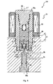
- the configuration of the solenoid on-off valve 1 will be explained in reference to Figs. 1 to 5 .
- the solenoid on-off valve 1 includes a housing 2.
- the housing 2 includes a housing main body 3 formed integrally with the valve block and a solenoid case 4 configured to accommodate a below-described electromagnetic solenoid 31.
- the housing main body 3 includes a through hole 5 extending along an axis line L1 extending in an upper-lower direction. Both upper and lower ends of the through hole 5 are open, and a valve chest 5a that is an upper region of the through hole 5 is larger in diameter than a supply and discharge passage 5b that is a lower region of the through hole 5.
- a main valve seat 6 is formed on a periphery of an opening of the supply and discharge passage 5b, the opening facing the valve chest 5a.
- the main valve seat 6 is an annular protruding portion projecting in an upper direction, and a circular valve port 7 is formed on an inner side of a tip end of the main valve seat 6.
- a guide member 8 is inserted into the valve chest 5a through an upper opening thereof.
- the guide member 8 is a substantially cylindrical member.
- the guide member 8 threadedly engages with an inner peripheral surface of the housing main body 3 in a state where a lower portion thereof is inserted into the valve chest 5a. A seal between the inner peripheral surface of the housing main body 3 and an outer peripheral surface of the guide member 8 is being achieved.
- a lower end of the guide member 8 faces an outer peripheral edge 3a located on an outer side of the main valve seat 6 and is spaced apart from the outer peripheral edge 3a in an upper direction.
- a main valve body 10, a pilot valve body 11, and a plunger 12 are inserted through the guide member 8.
- the main valve body 10 includes a main valve main body 13 and a main valve seat portion 14.
- the main valve main body 13 is a substantially bottomed cylindrical member.
- the main valve main body 13 is inserted through the guide member 8 such that an opening thereof faces upward.
- the main valve main body 13 is slidable in the guide member 8 in the upper-lower direction.
- the main valve seat portion 14 is provided at a lower end of the main valve main body 13.
- the main valve seat portion 14 is an annular member made of synthetic rubber, synthetic resin, or the like.
- a lower surface of the main valve seat portion 14 is exposed in a lower direction.
- the main valve seat portion 14 is provided such that the exposed lower surface thereof faces the main valve seat 6.
- a tank space 15 is formed on a radially outer side of the main valve seat 6 on which the main valve seat portion 14 is seated as above.
- the tank space 15 is an annular space surrounded by the main valve body 10, the guide member 8, the housing main body 3, and the main valve seat 6.
- the tank space 15 is connected through the valve port 7 to the supply and discharge passage 5b located on a radially inner side of the main valve seat 6.
- a tank port 3b connected to the high-pressure tank (not shown) and a supply and discharge port 3c connected to a device (for example, a gas consuming unit or a filling device) located outside the high-pressure tank are formed on the housing main body 3.
- the tank space 15 is connected to the tank port 3b, and the supply and discharge passage 5b is connected to the supply and discharge port 3c.
- the tank port 3b, the tank space 15, the valve port 7, the supply and discharge passage 5b, and the supply and discharge port 3c constitute a valve passage 16 connecting the inside and outside of the high-pressure tank.
- a plurality of communication grooves 17 and a pilot passage 18 are formed on the main valve main body 13.
- the communication grooves 17 are grooves extending in the upper-lower direction and are formed on an outer peripheral surface of the main valve body 10. Both upper and lower ends of the communication grooves 17 are open, so that the communication grooves 17 connect a space (to be specific, a below-described communication space 35) located above the main valve body 10 and the tank space 15.
- the pilot passage 18 is a through hole extending in the upper-lower direction along an axis of the main valve body 10 (in the present embodiment, the axis of the main valve body 10 substantially coincides with the axis line L1).
- the pilot passage 18 is formed on a bottom portion of the main valve main body 13 so as to penetrate the bottom portion. Therefore, a lower opening of the pilot passage 18 faces the valve port 7 and connects the supply and discharge passage 5b and a valve internal space 19 that is a space in the main valve main body 13.
- a pilot valve seat 20 is formed on a periphery of an upper opening (to be specific, an opening facing the valve internal space 19) of the pilot passage 18.
- the pilot valve seat 20 is a protruding portion protruding in the upper direction and has a substantially annular shape.
- a stopper portion 21 is formed around the pilot valve seat 20.
- the stopper portion 21 is an annular step portion raised upward.
- the stopper portion 21 is formed along the entire periphery of an inner peripheral surface of the main valve body 10 in a circumferential direction.
- the stopper portion 21 is formed to be spaced apart from the pilot valve seat 20 in a radially outer direction, and the height thereof is lower than that of the pilot valve seat 20.
- the pilot valve body 11 is inserted into the valve internal space 19 so as to face the pilot valve seat 20 and the stopper portion 21.
- the pilot valve body 11 includes a valve main body 22 and a pilot valve seat portion 23.
- the valve main body 22 is formed in a substantially columnar shape and is inserted into the valve internal space 19.
- the valve main body 22 is slidable in the main valve body 10 in the upper-lower direction.
- the pilot valve seat portion 23 is provided at a lower end portion of the valve main body 22.
- the pilot valve seat portion 23 is a disc-shaped member made of synthetic rubber, synthetic resin, or the like. A lower surface of the pilot valve seat portion 23 is exposed in the lower direction.
- the pilot valve seat portion 23 is provided such that the lower surface thereof faces the pilot valve seat 20.
- a space is formed between a lower end of the valve main body 22 configured as above and the bottom portion of the main valve main body 13, and this space is a pilot chamber 24.
- the pilot chamber 24 is a substantially annular space surrounded by the valve main body 22, the main valve main body 13, and the pilot valve seat 20 and is located on the radially outer side of the pilot valve seat 20.
- the pilot valve seat 20 opens, the pilot chamber 24 is connected to the supply and discharge passage 5b through the pilot passage 18 and also connected to the space (to be specific, the below-described communication space 35) located above the main valve body 10 through a gap 24a located between an outer peripheral surface of the pilot valve body 11 and the inner peripheral surface of the main valve body 10.
- the pilot valve body 11 and the main valve body 10 configured as above are coupled to each other by a pilot pin 25, and the main valve body 10 moves in accordance with the movement of the pilot valve body 11.
- the pilot pin 25 is a substantially columnar pin member and is inserted through the main valve body 10 and the pilot valve body 11.
- the pilot pin 25 extends in a radial direction of the main valve main body 13. Both end portions of the pilot pin 25 are fittingly inserted into and fixed to an upper end portion of the main valve main body 13, and a middle portion thereof is inserted through a first insertion hole 26 formed on the pilot valve body 11.
- the first insertion hole 26 that is a main valve insertion hole penetrates the valve main body 22 in the radial direction.
- a diameter of the first insertion hole 26 is larger than an outer diameter of the pilot pin 25.
- a second insertion hole 27 is formed on the valve main body 22 so as to be located above the first insertion hole 26.
- the second insertion hole 27 that is a plunger insertion hole is a hole penetrating the valve main body 22 in the radial direction.
- a coupling pin 28 is inserted through the second insertion hole 27.
- the coupling pin 28 is a substantially columnar pin member.
- a diameter of the coupling pin 28 is smaller than an inner diameter of the second insertion hole 27. Both end portions of the coupling pin 28 project in the radially outer direction from the second insertion hole 27 and are fittingly inserted into and fixed to the plunger 12.
- the plunger 12 is made of a magnetic material and has a substantially bottomed cylindrical shape.
- the plunger 12 is inserted through the guide member 8 such that an opening thereof faces downward.
- the plunger 12 is positioned such that a lower end thereof faces an upper end of the main valve body 10 (to be specific, an upper end of the main valve main body 13).
- the upper end portion of the pilot valve body 11 is inserted into the opening of the plunger 12.
- the coupling pin 28 penetrates the plunger 12 and the pilot valve body 11 in the radial direction. Both end portions of the coupling pin 28 are fixed to a lower end portion of the plunger 12. With this, the plunger 12 and the pilot valve body 11 are coupled to each other such that the pilot valve body 11 moves in accordance with the movement of the plunger 12.
- the plunger 12 includes a flange 12a at an upper end portion thereof.
- the flange 12a is formed along the entire periphery in the circumferential direction and projects in the radially outer direction.
- An inner diameter of an upper end portion of the guide member 8 is set so as to correspond to an outer diameter of the flange 12a, and an inner diameter of a lower end portion of the guide member 8 is smaller than that of the upper end portion thereof. Therefore, a step portion 8a is formed on an inner peripheral surface of the guide member 8 so as to be located between an upper end region and lower end region of the inner peripheral surface of the guide member 8.
- the flange 12a is supported by the step portion 8a.
- a first spring 29 (valve body biasing unit) is accommodated in the plunger 12.
- the first spring 29 is a so-called compression coil spring.
- the first spring 29 is provided between an upper end of the pilot valve body 11 and a ceiling surface of the plunger 12 so as to be compressed.
- the first spring 29 biases the valve main body 22 in the lower direction and presses the pilot valve seat portion 23 against the pilot valve seat 20.
- the first spring 29 biases the pilot valve body 11 in a closing direction and presses the pilot valve body 11 against the pilot valve seat 20 to cause the pilot valve body 11 to be seated on the pilot valve seat 20.
- the pilot pin 25 is provided in the first insertion hole 26 to be spaced apart from a lower inner peripheral surface of the pilot valve body 11 such that the pilot pin 25 does not contact the pilot valve body 11 which is seated as above.
- the coupling pin 28 is provided in the second insertion hole 27 to be spaced apart from an upper inner peripheral surface of the pilot valve body 11 such that the coupling pin 28 does not contact the pilot valve body 11 which is seated on the pilot valve seat 20 in a state where the plunger 12 is supported by the step portion 8a of the guide member 8. When the plunger 12 is lifted in the upper direction, the coupling pin 28 contacts the inner peripheral surface of the pilot valve body 11 to lift up the pilot valve body 11.
- a fixed magnetic pole 30 is provided above the plunger 12 configured as above.
- the fixed magnetic pole 30 is a substantially columnar member made of a ferromagnetic material and is being inserted into an upper opening of the guide member 8.
- the fixed magnetic pole 30 threadedly engages with the guide member 8 in a state where a seal between an outer peripheral surface of the fixed magnetic pole 30 and the guide member 8 is being achieved.
- a lower end of the fixed magnetic pole 30 faces an upper end of the plunger 12.
- a flange portion 30a projecting in the radially outer direction is formed along the entire periphery of an upper end portion of the fixed magnetic pole 30 in the circumferential direction.
- the electromagnetic solenoid 31 is located on an outer side of the housing main body 3 (to be specific, on an upper side of the housing main body 3) and is accommodated in the solenoid case 4.
- the electromagnetic solenoid 31 includes a bobbin 32 and a coil wire 33.
- the bobbin 32 is formed in a substantially cylindrical shape and is externally provided on the guide member 8.
- the coil wire 33 winds around an outer peripheral surface of the bobbin 32.
- a controller not shown, is electrically connected to the coil wire 33. By supplying a current from the controller to the coil wire 33, the coil wire 33 is excited to magnetize the plunger 12. By magnetizing the plunger 12 as above, the plunger 12 is adsorbed by the fixed magnetic pole 30 to be lifted in the upper direction. That is, the electromagnetic solenoid 31 can generate an exciting force by supplying the current thereto and thus can cause the plunger 12 to move in the upper direction.
- a second spring 34 (plunger biasing unit) is provided in the guide member 8.
- the second spring 34 is a so-called compression coil spring.
- the second spring 34 is provided between the plunger 12 and the fixed magnetic pole 30 so as to be compressed.
- the second spring 34 biases the plunger 12 in a direction against the exciting force of the electromagnetic solenoid 31, that is, in the lower direction. Since the plunger 12 is biased by the second spring 34, the plunger 12 is pressed in the lower direction to be seated on the step portion 8a of the guide member 8.
- a relative positional relation between the coupling pin 28 and the valve main body 22, a relative positional relation between the plunger 12 and the main valve body 10, a relative positional relation between the pilot pin 25 and the valve main body 22, and a relative positional relation between the pilot valve body 11 and the stopper portion 21 when the main valve body 10 and the pilot valve body 11 are respectively located at the valve port close position and the passage close position are preset.
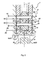
- these relative positional relations will be explained in reference to Fig. 2 .
- the coupling pin 28 is provided in the second insertion hole 27 so as to be spaced apart from the inner peripheral surface (hereinafter simply referred to as "upper inner peripheral surface"), which forms the second insertion hole 27, by a gap A1 (fourth clearance) located above the coupling pin 28 and a gap A2 (second clearance) located below the coupling pin 28.
- Each of the gaps A1 and A2 denotes the size of an interval in the upper-lower direction, and the same is true for below-described gaps A3 to A6.
- the plunger 12 and the main valve body 10 are provided so as to be spaced apart from each other by a gap A3 (first clearance) in the upper-lower direction.
- the communication space 35 having an annular shape is formed between the plunger 12 and the main valve body 10.
- the pilot pin 25 is provided in the first insertion hole 26 so as to be spaced apart from the inner peripheral surface (hereinafter simply referred to as "lower inner peripheral surface"), which forms the first insertion hole 26, by a gap A4 (fifth clearance) located above the pilot pin 25 and a gap A5 located below the pilot pin 25.
- the pilot valve body 11 and the main valve body 10 are provided so as to be spaced apart from each other by a gap A6 (third clearance).
- each of the gaps A1 and A4 is larger than the gap A6 (to be specific, A1>A6, A4>A6), and the gap A2 is larger than the gap A3. It is preferable that the gaps A1 and A5 be as large as possible such that the pilot pin 25 and the coupling pin 28 do not contact the valve main body 22 when, for example, the pilot valve body 11 vibrates. If the gaps A1 and A5 are increased without changing the stroke of the plunger 12, the opening (clearance between the main valve body 10 and the main valve 6) of the main valve 6 decreases. Therefore, the opening of the main valve 6 needs to be increased as much as possible while securing a minimum necessary opening of the main valve 6.
- the solenoid on-off valve 1 configured as above is a so-called normally closed on-off valve.
- the main valve body 10 When the current is not supplied to the electromagnetic solenoid 31, the main valve body 10 is located at the valve port close position, and the pilot valve body 11 is located at the passage close position. With this, the valve port 7 and the pilot passage 18 are closed, the communication between the tank port 3b and the supply and discharge port 3c is blocked, and the solenoid on-off valve 1 is in a closed state (see Fig. 2 ).
- the solenoid on-off valve 1 includes a manual operation rod 36.
- the manual operation rod 36 has a substantially columnar shape and is being inserted through the supply and discharge passage 5b.
- the manual operation rod 36 includes a head portion 36a at a base end portion thereof.
- the head portion 36a is larger in diameter than the other portion of the manual operation rod 36.
- the supply and discharge passage 5b in the vicinity of a lower opening is larger in diameter than the other portion thereof so as to correspond to the shape of the manual operation rod 36.
- the head portion 36a of the manual operation rod 36 threadedly engages with the supply and discharge passage 5b in the vicinity of the lower opening.
- a hexagonal hole, which opens in the lower direction, is formed on the head portion 36a of the manual operation rod 36.
- a tip end (upper end) of the manual operation rod 36 is located in the vicinity of the lower end of the main valve body 10.
- the pilot valve body 11 moves relative to the main valve body 10 in the opening direction and separates from the pilot valve seat 20 (passage open position).
- the pilot passage 18 opens.
- the tank space 15 and the supply and discharge passage 5b are connected to each other through the communication groove 17, the communication space 35, the gap 24a, the pilot chamber 24, and the pilot passage 18.
- the gas in the high-pressure tank is supplied through the tank port 3b to the supply and discharge passage 5b.
- the internal pressure of the supply and discharge passage 5b increases. Therefore, the pressure difference between the tank space 15 and the supply and discharge passage 5b decreases, and an acting force necessary to cause the main valve body 10 to move in the opening direction decreases.
- the valve can be opened even if the exciting force applied to the plunger 12 is small.
- the electromagnetic solenoid 31 can be reduced in size.
- valve port 7 opens.
- the valve port 7 opens, the tank space 15 and the supply and discharge passage 5b are directly connected to each other through the valve port 7, and the gas in the high-pressure tank is directly supplied from the tank space 15 to the supply and discharge passage 5b (see an arrow A in Fig. 3 ).
- the gas in the high-pressure tank can be discharged through the supply and discharge port 3c to be supplied to, for example, the gas consuming unit.
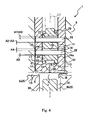
- the gap between the plunger 12 and the main valve body 10 is equal to the sum of the gaps A1, A3, and A5, that is, is further larger than the gap A3 that is the gap when the valve is closed.
- the gas to be filled (hereinafter simply referred to as "fill gas") is supplied through the supply and discharge port 3c to the supply and discharge passage 5b.
- the main valve body 10 receives the acting force of the fill gas in the opening direction to move in the opening direction and separate from the main valve seat 6.
- the valve port 7 opens, and the fill gas in the supply and discharge passage 5b is introduced through the valve port 7, the tank space 15, and the tank port 3b to the high-pressure tank (see an arrow B in Fig. 4 ).
- the high-pressure tank is filled with the gas.
- the main valve body 10 moves in the opening direction by the acting force of the fill gas.
- the pilot valve body 11 receives the acting force of the fill gas flowing through the pilot passage 18 to be slightly lifted up from the pilot valve seat 20.
- a pressure receiving area of the main valve body 10 is larger than that of the pilot valve body 11, the pressure receiving area being an area which receives the acting force of the fill gas. Therefore, the pilot valve body 11 is maintained so as to be mostly in close contact with the pilot valve seat 20.
- the main valve body 10 and the pilot valve body 11 move integrally in a state where they are in close contact with each other.
- the pilot pin 25 is spaced apart from the lower inner peripheral surface by the gap A4 located above the pilot pin 25 and the gap A5 located below the pilot pin 25, and the pilot pin 25 and the lower inner peripheral surface do not contact each other. Therefore, the pilot pin 25 can be prevented from breaking by contacting with the lower inner peripheral surface of the pilot valve body 11 during the filling operation.
- the first spring 29 can absorb a force of the main valve body 10 pressing the pilot valve body 11.
- a force of the pilot valve seat 20 pressing the pilot valve seat portion 23 can be suppressed.
- the gas leakage in the closed state can be prevented from occurring by largely deforming or damaging the pilot valve seat portion 23 by the filling operation of the gas.
- the solenoid on-off valve 1 having higher reliability can be provided.
- the main valve body 10 moves relative to the plunger 12 in the opening direction by the gap A3 (relative movement distance)
- the main valve body 10 contacts the plunger 12.
- the movement of the main valve body 10 relative to the plunger 12 in the opening direction stops.
- the plunger 12 and the main valve body 10 move integrally in the opening direction.
- the plunger 12 and the main valve body 10 are pushed by the fill gas in the opening direction, the plunger 12 contacts the fixed magnetic pole 30, and the plunger 12 and the main valve body 10 are held at this position.
- the coupling pin 28 moves relative to the upper inner peripheral surface of the pilot valve body 11 in the lower direction and gets close to the upper inner peripheral surface.
- the relative movement distance of the main valve body 10 with respect to the plunger 12 in the opening direction is limited by the plunger 12 so as to be equal to or less than the gap A3, and the coupling pin 28 is spaced apart from the upper inner peripheral surface of the pilot valve body 11 by the gap A2 located below the coupling pin 28, the coupling pin 28 does not contact the upper inner peripheral surface of the pilot valve body 11.
- the coupling pin 28 stops at such a position as to be spaced apart from the upper inner peripheral surface by a gap located below the coupling pin 28, the gap being obtained by subtracting the gap A3 from the gap A2, and is maintained substantially at this position.
- substantially the gap obtained by subtracting the gap A3 from the gap A2 is always formed between the coupling pin 28 and the upper inner peripheral surface. Therefore, the coupling pin 28 can be prevented from being damaged by the impact generated when the coupling pin 28 contacts the pilot valve body 11 which rapidly moves immediately after the start of the filling operation.
- the static shear force is not applied to the coupling pin during the filling operation.
- the coupling pin 28 is spaced apart from the upper inner peripheral surface by a gap located above the coupling pin 28, the gap being a sum of the gaps A1 and A3.
- the solenoid on-off valve 1 can control the open and close states of the valve port 7 by switching the current supplied to the electromagnetic solenoid.
- the solenoid on-off valve 1 can allow the flow of the gas from the supply and discharge passage 5a to the tank space and block the opposite flow.
- a valve having an electromagnetic open-close function and a check valve function can be realized by the solenoid on-off valve 1.
- the manual operation rod 36 By turning the manual operation rod 36 in a direction opposite to the direction in which the manual operation rod 36 is turned when forcibly opening the valve port 7, the manual operation rod 36 moves in the lower direction.
- the main valve body 10 By causing the manual operation rod 36 to move in the lower direction after the valve port 7 is forcibly opened by the manual operation rod 36, the main valve body 10 is moved in the closing direction and is then seated on the main valve seat 6. With this, the valve port 7 is closed, and the communication between the tank space 15 and the supply and discharge passage 5b is blocked. Thus, the discharge of the gas in the high-pressure tank can be stopped.
- the plastic deformation of the pilot valve seat portion 23 occurs due to aging degradation or use conditions in some cases. If the pilot valve body 11 moves in the closing direction by a distance equal to the gap A6 due to this plastic deformation, the valve main body 22 contacts the stopper portion 21, and the pilot valve body 11 is limited so as not to move in the lower direction any more.
- the gap A6 is larger than each of the gap A1 and the gap A4. Therefore, even if the plastic deformation of the pilot valve seat portion 23 occurs, the leakage through the pilot passage 18 can be prevented from occurring when the pilot valve body 11 contacts the pilot pin 25 and the coupling pin 28 and the pilot valve seat portion 23 separates from the pilot valve seat 20.
- a solenoid on-off valve 1A according to Embodiment 2 of the present invention is similar in configuration to the solenoid on-off valve 1 according to Embodiment 1 of the present invention. Therefore, regarding the configuration of the solenoid on-off valve 1A according to Embodiment 2, only components different from those of the solenoid on-off valve 1 according to Embodiment 1 will be explained. The same reference signs are used for the same components, and a repetition of the same explanation is avoided.
- a lower end portion of a plunger 12A is inserted into the valve internal space 19 of the main valve body 10, and the main valve body 10 and the plunger 12A are coupled to each other by the coupling pin 28 so as to be able to move in accordance with each other.
- a pilot valve body 11A is accommodated in the plunger 12A and does not get out of the plunger 12A.
- the plunger 12A is inserted through the guide member 8 so as to be slidable.
- the plunger 12A includes a plunger main body 41 and a cover member 42.
- the plunger main body 41 has a substantially columnar shape and extends in the upper-lower direction.
- the plunger main body 41 includes a large-diameter portion 41 a, a small-diameter portion 41b, and an attachment portion 41c.
- the large-diameter portion 41a has a substantially columnar shape.
- An outer diameter of the large-diameter portion 41a is substantially equal to an inner diameter of the guide member 8.
- the large-diameter portion 41 a is provided in the guide member 8 so as to be slidable in the upper-lower direction.
- the second spring 34 is interposed between the upper end portion of the large-diameter portion 41a and the fixed magnetic pole 30.
- the small-diameter portion 41b is formed integrally with a lower end of the large-di
- the small-diameter portion 41b has a substantially columnar shape. An outer diameter of the small-diameter portion 41b is substantially equal to an inner diameter of the valve internal space 19.
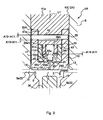
- the small-diameter portion 41b is inserted through the main valve body 10 so as to be slidable in the upper-lower direction. An upper end of the main valve body 10 through which the small-diameter portion 41b is inserted faces the lower end of the large-diameter portion 41a, and a gap A11 (sixth clearance) is formed between the main valve body 10 and the large-diameter portion 41 a.
- a communication space 35A having a circular shape is formed between the main valve body 10 and the large-diameter portion 41 a.
- a third insertion hole 43 (insertion hole) is formed on the small-diameter portion 41b so as to penetrate the small-diameter portion 41b in the radial direction.
- the coupling pin 28 is inserted through the third insertion hole 43. Both end portions of the coupling pin 28 extend up to the main valve body 10 and are fixed by the main valve body 10.
- the coupling pin 28 is provided so as to be spaced apart from an inner peripheral surface, which forms the third insertion hole 43, by a gap A 12 (seventh clearance) located above the coupling pin 28 and a gap A13 located below the coupling pin 28.
- the gap A12 is larger than the gap A11 (that is, A12>A11).
- the attachment portion 41c is formed integrally with a lower end of the small-diameter portion 41b.
- the attachment portion 41c has a substantially cylindrical shape and is further smaller in diameter than the small-diameter portion 41b.
- the attachment portion 41c extends in the lower direction from the lower end of the small-diameter portion 41b.
- the cover member 42 threadedly engages with an outer peripheral surface of the attachment portion 41c.
- the cover member 42 has a substantially cylindrical shape.
- An outer diameter of the cover member 42 is substantially equal to that of the small-diameter portion 41b.
- the gap 24a through which the gas can flow is formed between an outer peripheral surface of the cover member 42 and the inner peripheral surface of the main valve body 10.
- the gap 24a is connected to the communication space 35A.
- the cover member 42 includes an inner flange 42a projecting in a radially inner direction.
- the inner flange 42a is located at a tip end portion (lower end portion) of the cover member 42.
- the inner flange 42a has a substantially annular shape and is spaced apart from the tip end (lower end) of the attachment portion 41c in the lower direction.
- a pilot chamber 24A is formed between the inner flange 42a and the bottom portion of the main valve body 10.
- a valve body accommodating space 44 surrounded by an inner peripheral surface of the cover member 42 is formed between the inner flange 42a and the tip end of the attachment portion 41 c.
- the pilot valve body 11 A is accommodated in the valve body accommodating space 44.
- the pilot valve body 11A includes a seat holding portion 45 and a pilot valve seat portion 23A.
- the seat holding portion 45 is formed in a substantially cylindrical shape. An outer diameter of the seat holding portion 45 is smaller than an inner diameter of the cover member 42.
- the pilot valve seat portion 23A is provided in and fixed to the seat holding portion 45.
- the pilot valve seat portion 23A has a substantially columnar shape. An attachment flange 23a projecting in the radially outer direction is formed along the entire periphery of a middle portion of the pilot valve seat portion 23A in the circumferential direction.
- the seat holding portion 45 includes a concave portion 45a corresponding to the attachment flange 23a.
- the pilot valve seat portion 23A is attached to the seat holding portion 45 so as not to be detached therefrom.
- a tip end portion (lower end portion) of the pilot valve seat portion 23A is projecting from the seat holding portion 45.
- the pilot valve body 11A configured as above is slidable in the upper-lower direction in the valve body accommodating space 44.
- the seat holding portion 45 of the pilot valve body 11A is formed to be larger in diameter than a radially inner hole of the inner flange 42a of the cover member 42, so that the pilot valve body 11A does not get out of the radially inner hole by the inner flange 42a. Further, the portion (the tip end portion of the pilot valve seat portion 23A) projecting from the seat holding portion 45 of the pilot valve body 11A is inserted through the radially inner hole of the inner flange 42a of the cover member 42 to be exposed in the lower direction.
- the tip end portion of the pilot valve seat portion 23A faces the pilot valve seat 20 in the upper-lower direction and can be seated on the pilot valve seat 20 (see Fig. 7 ).
- the first spring 29A is accommodated in the attachment portion 41c.
- the first spring 29A biases the pilot valve body 11A in the lower direction.
- the biased pilot valve body 11A is supported by the inner flange 42a, is spaced apart from the attachment portion 41c in the lower direction by a gap A14, and is seated on the pilot valve seat 20 in the closed state. With this, the pilot passage 18 is being closed.
- the gap A 14 is larger than the gap A11 (to be specific, A14>A11).
- the tank space 15 and the supply and discharge passage 5b are connected to each other through the communication groove 17, the communication space 35A, the gap 24a, the pilot chamber 24A, and the pilot passage 18, and the internal pressure of the supply and discharge passage 5b increases. With this, the pressure difference between the tank space 15 and the supply and discharge passage 5b decreases, and the acting force necessary to cause the main valve body 10 to move in the opening direction can be reduced.
- the exciting force applied to the plunger 12A can be reduced, and the electromagnetic solenoid 31 can be reduced in size.
- the plunger 12A When the supply of the current to the electromagnetic solenoid 31 is continued even after the pilot passage 18 is opened, the plunger 12A is continued to be lifted up. Then, the inner peripheral surface of the plunger 12A contacts the coupling pin 28, and the main valve body 10 is lifted up by the coupling pin 28. With this, the main valve body 10 moves in the opening direction and separates from the main valve seat 6 (valve port open position). Thus, the valve port 7 opens, and the gas in the high-pressure tank directly flows from the tank space 15 to the supply and discharge passage 5b (see an arrow D in Fig. 7 ).
- the coupling pin 28 is spaced apart from the inner peripheral surface of the plunger 12 by a gap located below the coupling pin 28, the gap being the sum of the gaps A12 and A13.
- a gap between the main valve body 10 and the large-diameter portion 41 a is equal to the sum of the gaps A11 and A 13.
- the plunger 12A moves in the lower direction (closing direction) by the biasing force of the second spring 34. With this, the pilot valve body 11A also moves in the closing direction, and the pilot valve body 11A is then seated on the pilot valve seat 20 to close the pilot passage 18. After the pilot valve body 11A is seated on the pilot valve seat 20, the main valve body 10 is pressed in the closing direction by the pilot valve body 11A to move in the closing direction. Then, the main valve body 10 is seated on the main valve seat 6 to close the valve port 7. Thus, the solenoid on-off valve 1A is set to the closed state (see Fig. 7 ).
- the pilot valve body 11A receives the acting force of the fill gas flowing through the pilot passage 18 to be slightly lifted up from the pilot valve seat 20.
- the pressure receiving area of the main valve body 10 is larger than that of the pilot valve body 11A, the pressure receiving area being an area which receives the acting force of the fill gas. Therefore, the pilot valve body 11A is maintained so as to be mostly in close contact with the pilot valve seat 20.
- the pilot valve body 11A is biased by the first spring 29A in a state where the pilot valve body 11A is spaced apart from the lower end of the attachment portion 41 c of the plunger 12A by a gap obtained by subtracting the gap A11 from the gap A14.
- a force of the main valve body 10 pressing the pilot valve body 11A can be absorbed by the first spring 29A.
- a force of the pilot valve seat 20 pressing the pilot valve seat portion 23 can be suppressed.
- the gas leakage in the closed state can be prevented from occurring by largely deforming or damaging the pilot valve seat portion 23 by the filling operation of the gas.
- the solenoid on-off valve 1A having higher reliability can be provided.
- the main valve body 10 moves in the opening direction, the main valve body 10 contacts the large-diameter portion 41a. With this, the movement of the main valve body 10 relative to the plunger 12A stops. Then, the plunger 12A and the main valve body 10 move integrally in the opening direction. The plunger 12A and the main valve body 10 are pushed by the fill gas in the opening direction, the plunger 12A contacts the fixed magnetic pole 30, and the plunger 12A and the main valve body 10 are held at this position.
- the coupling pin 28 moves relative to the inner peripheral surface of the plunger 12A in the upper direction and gets close to the inner peripheral surface.
- the main valve body 10 then contacts the plunger 12A, and the movement thereof stops. With this, the movement of the coupling pin 28 also stops. Therefore, the coupling pin 28 does not contact the inner peripheral surface of the plunger 12A.
- the coupling pin 28 stops at such a position as to be spaced apart from the inner peripheral surface by a gap located above the coupling pin 28, the gap being obtained by subtracting the gap A11 from the gap A12, and is maintained substantially at the position.
- substantially the gap obtained by subtracting the gap A11 from the gap A12 is always formed between the coupling pin 28 and the inner peripheral surface. Therefore, the coupling pin 28 can be prevented from being damaged by the impact generated when the coupling pin 28 contacts the plunger 12A which rapidly moves immediately after the start of the filling operation. In addition, the static shear force is not applied to the coupling pin during the filling operation.
- the coupling pin 28 is spaced apart from the inner peripheral surface of the plunger 12A by a gap located below the coupling pin, the gap being the sum of the gaps A11 and A 13.
- the manual operation rod 36 By turning the manual operation rod 36 in a direction opposite to the direction in which the manual operation rod 36 is turned when forcibly opening the valve port 7, the manual operation rod 36 moves in the lower direction.
- the main valve body 10 By causing the manual operation rod 36 to move in the lower direction after the valve port 7 is forcibly opened by the manual operation rod 36, the main valve body 10 is moved in the closing direction and is then seated on the main valve seat 6. With this, the valve port 7 is closed, and the communication between the tank space 15 and the supply and discharge passage 5b is blocked. Thus, the discharge of the gas in the high-pressure tank can be stopped.
- the plunger 12A moves in the closing direction.
- the main valve body 10 includes the stopper portion 21. If the plunger 12A moves in the closing direction by a distance A15, the plunger 12A contacts the stopper portion 21 and does not move in the lower direction any more.
- the gap A15 is smaller than the gap A12. Therefore, even if the plastic deformation of the pilot valve seat portion 23A occurs, the leakage through the pilot passage 18 can be prevented from occurring when the plunger 12A contacts the coupling pin 28 and the pilot valve seat portion 23A separates from the pilot valve seat 20.
- the number of pins is smaller than that in the solenoid on-off valve 1 of Embodiment 1. Therefore, the number of members which may break or be damaged can be reduced, and the reliability can be further improved.
- the pilot pin 25 and the coupling pin 28 are displaceable relative to the pilot valve body 11.
- the pilot pin 25 and the coupling pin 28 may be fitted in the pilot valve body 11 so as not to be displaceable relative to the pilot valve body 11.
- a hole, such as the first insertion hole 26, is formed on the main valve body 10 and a hole, such as the second insertion hole 2, is formed on the plunger 12 such that the pilot pin 25 and the coupling pin 28 are displaceable relative to the main valve body 10 and the plunger 12.
- the coupling pin 28 is provided so as to be displaceable relative to the plunger 12A.
- the coupling pin 28 may be fitted in the plunger 12A so as not to be displaceable relative to the plunger 12A.
- a hole, such as the third insertion hole 26, is formed on the main valve body 10 such that the coupling pin 28 is displaceable relative to the main valve body 10.
- Embodiments 1 and 2 have explained the solenoid on-off valves 1 and 1A (to be specific, container main valves) that are on-tank type valves.
- the solenoid on-off valves 1 and 1A may be in-tank type solenoid on-off valves or may be solenoid on-off valves, each of which is not mounted on the opening of the high-pressure tank.
- each of the solenoid on-off valves 1 and 1A may be any valve as long as the valve is provided on a passage connecting the gas consuming unit and the high-pressure tank.
- the present invention is applicable to a solenoid on-off valve capable of switching between the discharge and non-discharge of the gas from the tank by the electromagnetic solenoid and filling the tank with the gas.
Landscapes
- Engineering & Computer Science (AREA)
- General Engineering & Computer Science (AREA)
- Mechanical Engineering (AREA)
- Sustainable Development (AREA)
- Sustainable Energy (AREA)
- Chemical & Material Sciences (AREA)
- Chemical Kinetics & Catalysis (AREA)
- Electrochemistry (AREA)
- General Chemical & Material Sciences (AREA)
- Life Sciences & Earth Sciences (AREA)
- Manufacturing & Machinery (AREA)
- Magnetically Actuated Valves (AREA)
- Fuel Cell (AREA)
Abstract
A main valve body 10 is provided in a housing 3 included in a solenoid on-off valve 1. A pilot passage 18 is formed on the main valve body 10, and a pilot valve body 11 is inserted into the pilot passage 18 so as to open and close the pilot passage 18. The pilot valve body 11 and the main valve body 10 move in accordance with the movement of a plunger 12 which is movable in an opening direction. The plunger 12 and the pilot valve body 11 are coupled to each other by a coupling pin 28 inserted through the plunger 12 and the pilot valve body 11. The coupling pin 28 is provided so as to be displaceable relative to the pilot valve body 11. When the main valve body 10 is pushed in the opening direction and before the coupling pin 28 contacts the pilot valve body 11, the plunger 12 stops the movement of the main valve body 10 relative to the plunger 12 in the opening direction. With this, it is possible to provide the solenoid on-off valve capable of preventing a shear force from acting on the coupling pin when the valve port is opened by pushing the main valve body.
Description
- The present invention relates to a solenoid on-off valve capable of switching between the discharge and non-discharge of a gas from a tank by an electromagnetic solenoid and filling the tank with the gas.
- A valve block is provided on an opening of a tank, and a discharging channel and filling channel, each of which connects the inside and outside of the tank, are formed on the valve block. The discharging channel is a channel through which a gas in the tank is discharged, and the filling channel is a channel through which the gas is filled in the tank. The valve block generally includes a solenoid on-off valve and a check valve. The solenoid on-off valve has a function of opening and closing the discharging channel in accordance with the existence or non-existence of a current flowing therethrough, and the check valve has a function of allowing the flow of the gas from the outside of the tank to the filling channel and blocking the opposite flow.
- Since the valve block configured as above includes two systems that are a discharging system and a filling system, the overall size thereof becomes large. Therefore, it is preferable that one system perform both discharging and filling operations. To realize this, a valve having both the function of the solenoid on-off valve and the function of the check valve is required. Known as the valve having these two functions is a pilot solenoid valve described in, for example,
PTL 1 orPTL 2. - The pilot solenoid valve (hereinafter simply referred to as "solenoid valve") described in each of
PTLs - The plunger is coupled to the main valve body and the pilot valve body by a pilot pin penetrating the main valve body and the pilot valve body. The plunger moves by driving an electromagnetic solenoid provided on an outer periphery of the plunger. The pilot valve body and the main valve body move in accordance with the movement of the plunger by the pilot pin. The pilot valve body and the main valve body are separated from the respective seat portions in this order. To be specific, the orifice hole opens first, and the communication channel then opens. When the communication channel opens, a hydrogen gas is discharged from a hydrogen tank to be supplied to a fuel cell.
- In the solenoid valve, the pilot valve body is being biased by a spring. When the electromagnetic solenoid is not operating, the pilot valve body is pressed against the pilot seat portion by a main valve spring to close the orifice hole. In addition, the main valve body is pressed against the main valve seat portion by the main valve spring through the pilot valve body to close the communication channel. With this, when the electromagnetic solenoid is not operating, the hydrogen gas is not discharged from the hydrogen tank. Meanwhile, when the hydrogen gas is supplied from the outside of the hydrogen tank to the communication channel to fill the hydrogen tank with the hydrogen gas, the main valve body is pushed up by the pressure of the hydrogen gas to separate from the main valve seat portion. Therefore, when the hydrogen gas is supplied to the communication channel, the main valve body is pushed up by the pressure of the hydrogen gas, the communication channel opens, and the hydrogen tank is filled with the hydrogen gas.
- PTL 1: Japanese Laid-Open Patent Application Publication No.
2005-163896 2009-210120 - According to the solenoid valve described in each of
PTLs - Meanwhile, when filling the hydrogen tank with the hydrogen gas, the main valve body is lifted up with the pilot valve body seated on the pilot seat portion. According to the solenoid valve described in
PTL 1, when the pilot valve body contacts the pilot pin and is not lifted up any more, the pilot seat portion is sandwiched between the pilot valve body and the main valve body which is being lifted up by the pressure of the hydrogen gas, and receives from the pilot valve body a force corresponding to the pressing force. As a result, problems, such as the deterioration of the pilot seat portion, occur. - To solve such problems, according to the solenoid valve described in
PTL 2, when the main valve body is pushed up, the main valve body contacts the pilot pin before the pilot valve body contacts the pilot pin, and the pilot valve body is pressed against the pilot seat portion by a pilot valve spring. With this, only a pressing force corresponding to a press force of the pilot valve spring is applied to the pilot seat portion. Thus, the pressing force that the pilot seat portion receives can be reduced. Therefore, the deterioration of the pilot seat portion of, for example, the solenoid valve described inPTL 1 can be reduced. - According to the solenoid valve described in
PTL 2, the main valve body having been pushed up by the hydrogen gas contacts the pilot pin. The hydrogen gas supplied in the filling operation has high pressure. An internal pressure of the hydrogen tank is considerably low although it depends on the amount of hydrogen gas used. Therefore, a pressure difference between the inside and outside of the hydrogen tank is large, so that a pushed-up speed of the main valve body immediately after the start of the filling operation, that is, a pushed-up speed of the main valve body when the communication channel starts opening is considerably high. However, the plunger hardly moves and is maintained at an original position. Therefore, the main valve body collides with the pilot pin at a considerably high relative speed, and a strong impact shear force is applied to the pilot pin. Thus, the pilot pin may be damaged by the impact shear force. Even if the pilot pin has endured the impact shear force, the main valve body is being pressed against the pilot pin by the supplied hydrogen gas in the filling operation, so that a strong static shear force is being applied to the pilot pin supporting the main valve body. Also in the solenoid valve described inPTL 1, at the time of the start of the filling operation and during the filling operation, the pilot valve body seated on the main valve body contacts the pilot pin, so that the pilot pin may be damaged during the filling operation. - As above, since the strong impact shear force and the strong static shear force are applied to the pilot pin at the time of the start of the filling operation and during the filling operation, the strength of the pilot pin needs to be increased such that the pilot pin can endure these shear forces. However, if the outer diameter of the pilot pin is increased to improve the strength of the pilot valve body, the outer diameter of the solenoid valve becomes large. Therefore, it is preferable that the strong shear force be not applied to the pilot pin.
- Here, an object of the present invention is to provide a solenoid on-off valve configured such that the shear force is not applied to the pilot pin (coupling pin) when the main valve body is pushed and the communication channel (valve port) opens to fill the tank with the gas.
- A solenoid on-off valve of the present invention includes: a housing including a tank space connected to a tank port, a supply and discharge space connected to a supply and discharge port, and a valve port connecting the tank space and the supply and discharge space; a main valve body configured to move between a valve port close position where the main valve body closes the valve port and a valve port open position where the main valve body opens the valve port and including a pilot passage connected to the tank space and the supply and discharge space; a pilot valve body configured to move between a passage close position where the pilot valve body is seated on the main valve body to close the pilot passage and a passage open position where the pilot valve body separates from the main valve body to open the pilot passage; a plunger configured to be movable in an opening direction and cause the pilot valve body and the main valve body to move to the passage open position and the valve port open position in this order when the plunger moves in the opening direction; an electromagnetic solenoid configured to generate an exciting force to cause the plunger to move in the opening direction; a plunger biasing unit configured to bias the plunger in a closing direction against the exciting force of the electromagnetic solenoid; and a coupling pin inserted through two members that are the plunger and the pilot valve body or two members that are the plunger and the main valve body and configured to be provided such that the two members are able to move in accordance with each other and are displaceable relative to each other, wherein when the main valve body is pushed in the opening direction, a movement of the main valve body relative to the plunger in the opening direction is stopped such that the coupling pin does not contact the two members.
- According to the present invention, when the electromagnetic solenoid generates the exciting force, the plunger moves in the opening direction. With this, the pilot valve body first moves to the passage open position, and the pilot passage opens. Thus, the pressure in the supply and discharge space increases. Then, the pressure difference between the tank space and the supply and discharge space decreases, and a force necessary to cause the main valve body to move in the opening direction decreases. Therefore, even if the exciting force of the electromagnetic solenoid is small, the main valve body can be caused to move to the valve port open position in accordance with the movement of the plunger. When the main valve body moves to the valve port open position and the valve port opens, the tank space and the supply and discharge space are directly connected to each other. With this, the gas can be discharged. Moreover, when the gas is supplied to the supply and discharge space to fill the tank with the gas, the main valve body is caused to move in the opening direction by the gas. With this, the valve port opens, and the gas in the supply and discharge space can be introduced through the valve port, the tank space, and the tank port to the tank and filled in the tank. As above, a valve having an electromagnetic open-close function and a check valve function can be realized by the solenoid on-off valve of the present invention.
- Moreover, in the present invention, when the main valve body is pushed by the gas to move in the opening direction, the coupling pin moves relative to one (opponent member) of the two members. By the movement of the coupling pin, the coupling pin is about to collide with the opponent member. However, before the coupling pin contacts the opponent member, the movement of the main valve body relative to the plunger in the opening direction is stopped. Therefore, the large shear force can be prevented from acting on the coupling pin as in conventional technologies by the collision of the coupling pin with the opponent member. Therefore, the breakage of the coupling pin can be prevented. Moreover, since the stiffness of the coupling pin can be reduced, the outer diameter of the coupling pin can be reduced.
- In the above invention, it is preferable that: the coupling pin couple the plunger with the pilot valve body; the plunger be provided to be spaced apart from the main valve body in the open direction by a first clearance when the main valve body is located at the valve port close position; the pilot valve body include a plunger insertion hole; the coupling pin be fixed to the plunger, be inserted through the plunger insertion hole so as to be movable, and be provided to be spaced apart from a surface, which forms the plunger insertion hole, in the opening direction by a second clearance when the main valve body is located at the valve port close position; and the second clearance be larger than the first clearance.
- According to the above configuration, the coupling pin is fixed to the plunger. Therefore, when the main valve body is pushed by the gas to move in the opening direction, the coupling pin moves relative to the main valve body in the closing direction in the plunger insertion hole. Since the plunger and the main valve body are spaced apart from each other only by the first clearance, the main valve body stops moving after it has moved relative to the plunger in the opening direction by the first clearance. Meanwhile, the coupling pin is spaced apart from the surface, which forms the insertion hole, in the opening direction by the second clearance and can move in the closing direction in the insertion hole by the second clearance that is larger than the first clearance. Therefore, even if the main valve body is pushed in the opening direction, the coupling pin does not contact the pilot valve body, and the shear force can be prevented from acting on the coupling pin during the filling operation.
- In the above invention, it is preferable that: the pilot valve body and the main valve body be coupled to each other by the pilot pin so as to be movable in accordance with each other, the pilot pin being inserted through the pilot valve body and the main valve body; and the pilot pin be provided so as not to contact the pilot valve body or the main valve body when the main valve body is pushed in the opening direction.
- According to the above configuration, even if the main valve body is pushed in the opening direction and the pilot pin moves relative to the pilot valve body or the main valve body (target member), the pilot pin does not contact the target member. Therefore, the large shear force can be prevented from acting on the pilot pin by the contact of the pilot pin with the target member. On this account, the breakage of the pilot pin can be prevented. Moreover, since the stiffness of the pilot pin can be reduced, the outer diameter of the pilot pin can be reduced.
- In the above invention, it is preferable that: the pilot valve body include a valve main body which is inserted into the main valve body so as to be movable and a pilot valve seat portion which is provided on the valve main body and is seated on the main valve body to close the pilot passage; the pilot valve main body be accommodated so as to be spaced apart from the main valve body in the opening direction by a third clearance; the coupling pin be provided to be spaced apart from the surface, which forms the plunger insertion hole, in the closing direction by a fourth clearance when the pilot valve main body is located at the passage close position; the pilot valve main body further include a main valve insertion hole; the pilot pin be fixed to the main valve body, be inserted through the main valve insertion hole so as to be movable, and be provided to be spaced apart from a surface, which forms the main valve insertion hole, in the closing direction by a fifth clearance when the pilot valve body is located at the passage close position; and each of the fourth clearance and the fifth clearance be larger than the third clearance.
- According to the above configuration, in a case where the pilot valve main body moves down toward the main valve body by, for example, the plastic deformation of the pilot valve seat portion, the pilot valve main body contacts the main valve body before it contacts the coupling pin or the pilot pin. Thus, the pilot valve main body does not move down by the third clearance or more. Therefore, the pilot valve body can be prevented from separating from the main valve body without being seated on the main valve body by the contact of the pilot valve body with the coupling pin or the pilot pin. With this, the leakage from the pilot passage can be prevented.
- In the above invention, it is preferable that: the coupling pin couple the plunger with the main valve body; the plunger be provided to be spaced apart from the main valve body by a sixth clearance when the main valve body is located at the valve port close position; the plunger include an insertion hole; the coupling pin be fixed to the main valve body, be inserted through the insertion hole so as to be movable, and be provided to be spaced apart from a surface, which forms the insertion hole, in the closing direction by a seventh clearance when the main valve body is located at the valve port close position; and the seventh clearance be larger than the sixth clearance.
- According to the above configuration, the coupling pin is fixed to the main valve body. Therefore, when the main valve body is pushed by the gas to move in the opening direction, the coupling pin moves relative to the main valve body in the opening direction in the insertion hole. Since the plunger and the main valve body are spaced apart from each other only by the sixth clearance, the main valve body stops moving after it has moved relative to the plunger in the opening direction by the sixth clearance. Meanwhile, the coupling pin is spaced apart from the surface, which forms the insertion hole, in the opening direction by the seventh clearance or more and can move in the closing direction in the insertion hole by the seventh clearance that is larger than the sixth clearance. Therefore, even if the main valve body is pushed in the opening direction, the main valve body contacts the plunger before the coupling pin contacts the plunger. With this, the coupling pin does not contact the plunger, and the shear force can be prevented from acting on the coupling pin during the filling operation.
- In the above invention, it is preferable that: the plunger include a plunger main body and a cover member; the plunger main body include an attachment portion located in the opening direction; a cover member threadedly engage with the attachment portion; a valve space closed by the attachment portion be formed in the cover member; and the pilot valve body contact and be supported by the cover member in the valve space and be provided so as to be movable from a state where the pilot valve body contacts and is supported by the cover member.
- According to the above configuration, the pilot valve body can be caused to move in accordance with the plunger without the pin. With this, the number of members which may be damaged can be reduced, and the reliability can be further improved.
- In the above invention, it is preferable that: the pilot valve body be provided to be spaced apart from an end surface of the attachment portion by an eighth clearance when the pilot valve body is located at the passage close position; and the eighth clearance be larger than the sixth clearance.
- According to the above configuration, even if the valve body is pushed by the gas to move in the opening direction, the pilot valve body does not contact the attachment portion of the plunger main body. Therefore, the pilot valve body and the plunger can be prevented from being damaged.
- In the above invention, it is preferable that the solenoid on-off valve further include a valve body biasing unit configured to bias the pilot valve body toward the close position.
- According to the above configuration, when the main valve body is pushed, the pilot valve body which is seated on the main valve body is pushed by the main valve body. However, this pressing force can be absorbed by the valve body biasing unit. With this, the deformation and breakage of the pilot valve body can be prevented, and the gas leakage due to the deformation, breakage, or the like can be prevented.
- The present invention can provide the solenoid on-off valve capable of preventing the shear force from acting on the coupling pin when the main valve body is pushed to open the valve port.
-
- [
Fig. 1] Fig. 1 is a cross-sectional view showing a solenoid on-off valve according toEmbodiment 1 of the present invention. - [
Fig. 2] Fig. 2 is an enlarged cross-sectional view showing the vicinity (region X1) of a main valve body of the solenoid on-off valve shown inFig. 1 . - [
Fig. 3] Fig. 3 is an enlarged cross-sectional view showing a state where the solenoid on-off valve shown inFig. 2 is in an open state. - [
Fig. 4] Fig. 4 is an enlarged cross-sectional view showing a state where the solenoid on-off valve shown inFig. 2 is in a filling state. - [
Fig. 5] Fig. 5 is an enlarged cross-sectional view showing a state where the solenoid on-off valve shown inFig. 2 is manually opened. - [
Fig. 6] Fig. 6 is a cross-sectional view showing the solenoid on-off valve according toEmbodiment 2 of the present invention. - [
Fig. 7] Fig. 7 is an enlarged cross-sectional view showing the vicinity (region X2) of the main valve body of the solenoid on-off valve shown inFig. 6 . - [
Fig. 8] Fig. 8 is an enlarged cross-sectional view showing a state where the solenoid on-off valve shown inFig. 7 is in the open state. - [
Fig. 9] Fig. 9 is an enlarged cross-sectional view showing a state where the solenoid on-off valve shown inFig. 7 is in the filling state. - [
Fig. 10] Fig. 10 is an enlarged cross-sectional view showing a state where the solenoid on-off valve shown inFig. 7 is manually opened. - Hereinafter, solenoid on-off
valves Embodiments valves valves - A solenoid on-off
valve 1 according toEmbodiment 1 of the present invention is provided at a high-pressure tank (not shown) configured to store a gas to be supplied to a gas consuming unit, such as a natural gas engine or a fuel cell. The solenoid on-offvalve 1 is formed integrally with a valve block (not shown) on which a supply and discharge passage connecting the high-pressure tank and the gas consuming unit is formed. The solenoid on-offvalve 1 is provided on an opening of the high-pressure tank together with the valve block to close the opening. The solenoid on-offvalve 1 is configured to be able to control the discharge of the gas in the high-pressure tank and fill the high-pressure tank with the gas. Hereinafter, the configuration of the solenoid on-offvalve 1 will be explained in reference toFigs. 1 to 5 . - The solenoid on-off
valve 1 includes ahousing 2. Thehousing 2 includes a housing main body 3 formed integrally with the valve block and a solenoid case 4 configured to accommodate a below-describedelectromagnetic solenoid 31. The housing main body 3 includes a throughhole 5 extending along an axis line L1 extending in an upper-lower direction. Both upper and lower ends of the throughhole 5 are open, and avalve chest 5a that is an upper region of the throughhole 5 is larger in diameter than a supply anddischarge passage 5b that is a lower region of the throughhole 5. Amain valve seat 6 is formed on a periphery of an opening of the supply anddischarge passage 5b, the opening facing thevalve chest 5a. Themain valve seat 6 is an annular protruding portion projecting in an upper direction, and acircular valve port 7 is formed on an inner side of a tip end of themain valve seat 6. Aguide member 8 is inserted into thevalve chest 5a through an upper opening thereof. - The
guide member 8 is a substantially cylindrical member. Theguide member 8 threadedly engages with an inner peripheral surface of the housing main body 3 in a state where a lower portion thereof is inserted into thevalve chest 5a. A seal between the inner peripheral surface of the housing main body 3 and an outer peripheral surface of theguide member 8 is being achieved. Moreover, a lower end of theguide member 8 faces an outerperipheral edge 3a located on an outer side of themain valve seat 6 and is spaced apart from the outerperipheral edge 3a in an upper direction. Amain valve body 10, apilot valve body 11, and aplunger 12 are inserted through theguide member 8. - As shown in
Fig. 2 , themain valve body 10 includes a main valvemain body 13 and a mainvalve seat portion 14. The main valvemain body 13 is a substantially bottomed cylindrical member. The main valvemain body 13 is inserted through theguide member 8 such that an opening thereof faces upward. The main valvemain body 13 is slidable in theguide member 8 in the upper-lower direction. The mainvalve seat portion 14 is provided at a lower end of the main valvemain body 13. The mainvalve seat portion 14 is an annular member made of synthetic rubber, synthetic resin, or the like. A lower surface of the mainvalve seat portion 14 is exposed in a lower direction. The mainvalve seat portion 14 is provided such that the exposed lower surface thereof faces themain valve seat 6. When themain valve body 10 is located at a valve port close position as shown inFigs. 1 and2 , the mainvalve seat portion 14 is seated on themain valve seat 6 to close thevalve port 7. - A
tank space 15 is formed on a radially outer side of themain valve seat 6 on which the mainvalve seat portion 14 is seated as above. Thetank space 15 is an annular space surrounded by themain valve body 10, theguide member 8, the housing main body 3, and themain valve seat 6. Thetank space 15 is connected through thevalve port 7 to the supply anddischarge passage 5b located on a radially inner side of themain valve seat 6. Moreover, atank port 3b connected to the high-pressure tank (not shown) and a supply and dischargeport 3c connected to a device (for example, a gas consuming unit or a filling device) located outside the high-pressure tank are formed on the housing main body 3. Thetank space 15 is connected to thetank port 3b, and the supply anddischarge passage 5b is connected to the supply and dischargeport 3c. As above, thetank port 3b, thetank space 15, thevalve port 7, the supply anddischarge passage 5b, and the supply and dischargeport 3c constitute avalve passage 16 connecting the inside and outside of the high-pressure tank. When themain valve body 10 is seated on themain valve seat 6 to close thevalve port 7, the communication between thetank space 15 and the supply anddischarge passage 5b is blocked, that is, thevalve passage 16 is blocked. - A plurality of
communication grooves 17 and apilot passage 18 are formed on the main valvemain body 13. Thecommunication grooves 17 are grooves extending in the upper-lower direction and are formed on an outer peripheral surface of themain valve body 10. Both upper and lower ends of thecommunication grooves 17 are open, so that thecommunication grooves 17 connect a space (to be specific, a below-described communication space 35) located above themain valve body 10 and thetank space 15. Thepilot passage 18 is a through hole extending in the upper-lower direction along an axis of the main valve body 10 (in the present embodiment, the axis of themain valve body 10 substantially coincides with the axis line L1). Thepilot passage 18 is formed on a bottom portion of the main valvemain body 13 so as to penetrate the bottom portion. Therefore, a lower opening of thepilot passage 18 faces thevalve port 7 and connects the supply anddischarge passage 5b and a valveinternal space 19 that is a space in the main valvemain body 13. - Moreover, a
pilot valve seat 20 is formed on a periphery of an upper opening (to be specific, an opening facing the valve internal space 19) of thepilot passage 18. Thepilot valve seat 20 is a protruding portion protruding in the upper direction and has a substantially annular shape. Astopper portion 21 is formed around thepilot valve seat 20. Thestopper portion 21 is an annular step portion raised upward. Thestopper portion 21 is formed along the entire periphery of an inner peripheral surface of themain valve body 10 in a circumferential direction. Thestopper portion 21 is formed to be spaced apart from thepilot valve seat 20 in a radially outer direction, and the height thereof is lower than that of thepilot valve seat 20. Thepilot valve body 11 is inserted into the valveinternal space 19 so as to face thepilot valve seat 20 and thestopper portion 21. - The
pilot valve body 11 includes a valvemain body 22 and a pilotvalve seat portion 23. The valvemain body 22 is formed in a substantially columnar shape and is inserted into the valveinternal space 19. The valvemain body 22 is slidable in themain valve body 10 in the upper-lower direction. The pilotvalve seat portion 23 is provided at a lower end portion of the valvemain body 22. The pilotvalve seat portion 23 is a disc-shaped member made of synthetic rubber, synthetic resin, or the like. A lower surface of the pilotvalve seat portion 23 is exposed in the lower direction. The pilotvalve seat portion 23 is provided such that the lower surface thereof faces thepilot valve seat 20. When thepilot valve body 11 is located at a passage close position as shown inFigs. 1 and2 , the pilotvalve seat portion 23 is seated on thepilot valve seat 20 to close thepilot passage 18. - A space is formed between a lower end of the valve
main body 22 configured as above and the bottom portion of the main valvemain body 13, and this space is apilot chamber 24. Thepilot chamber 24 is a substantially annular space surrounded by the valvemain body 22, the main valvemain body 13, and thepilot valve seat 20 and is located on the radially outer side of thepilot valve seat 20. When thepilot valve seat 20 opens, thepilot chamber 24 is connected to the supply anddischarge passage 5b through thepilot passage 18 and also connected to the space (to be specific, the below-described communication space 35) located above themain valve body 10 through agap 24a located between an outer peripheral surface of thepilot valve body 11 and the inner peripheral surface of themain valve body 10. - The
pilot valve body 11 and themain valve body 10 configured as above are coupled to each other by apilot pin 25, and themain valve body 10 moves in accordance with the movement of thepilot valve body 11. Specifically, thepilot pin 25 is a substantially columnar pin member and is inserted through themain valve body 10 and thepilot valve body 11. Thepilot pin 25 extends in a radial direction of the main valvemain body 13. Both end portions of thepilot pin 25 are fittingly inserted into and fixed to an upper end portion of the main valvemain body 13, and a middle portion thereof is inserted through afirst insertion hole 26 formed on thepilot valve body 11. Thefirst insertion hole 26 that is a main valve insertion hole penetrates the valvemain body 22 in the radial direction. A diameter of thefirst insertion hole 26 is larger than an outer diameter of thepilot pin 25. Moreover, asecond insertion hole 27 is formed on the valvemain body 22 so as to be located above thefirst insertion hole 26. - The
second insertion hole 27 that is a plunger insertion hole is a hole penetrating the valvemain body 22 in the radial direction. Acoupling pin 28 is inserted through thesecond insertion hole 27. Thecoupling pin 28 is a substantially columnar pin member. A diameter of thecoupling pin 28 is smaller than an inner diameter of thesecond insertion hole 27. Both end portions of thecoupling pin 28 project in the radially outer direction from thesecond insertion hole 27 and are fittingly inserted into and fixed to theplunger 12. - The
plunger 12 is made of a magnetic material and has a substantially bottomed cylindrical shape. Theplunger 12 is inserted through theguide member 8 such that an opening thereof faces downward. Theplunger 12 is positioned such that a lower end thereof faces an upper end of the main valve body 10 (to be specific, an upper end of the main valve main body 13). The upper end portion of thepilot valve body 11 is inserted into the opening of theplunger 12. Thecoupling pin 28 penetrates theplunger 12 and thepilot valve body 11 in the radial direction. Both end portions of thecoupling pin 28 are fixed to a lower end portion of theplunger 12. With this, theplunger 12 and thepilot valve body 11 are coupled to each other such that thepilot valve body 11 moves in accordance with the movement of theplunger 12. - As shown in
Fig. 1 , theplunger 12 includes aflange 12a at an upper end portion thereof. Theflange 12a is formed along the entire periphery in the circumferential direction and projects in the radially outer direction. An inner diameter of an upper end portion of theguide member 8 is set so as to correspond to an outer diameter of theflange 12a, and an inner diameter of a lower end portion of theguide member 8 is smaller than that of the upper end portion thereof. Therefore, astep portion 8a is formed on an inner peripheral surface of theguide member 8 so as to be located between an upper end region and lower end region of the inner peripheral surface of theguide member 8. Theflange 12a is supported by thestep portion 8a. When themain valve body 10 is located at the valve port close position, theplunger 12 supported as above is spaced apart from themain valve body 10 in the upper-lower direction. - As shown in
Fig. 2 , a first spring 29 (valve body biasing unit) is accommodated in theplunger 12. Thefirst spring 29 is a so-called compression coil spring. Thefirst spring 29 is provided between an upper end of thepilot valve body 11 and a ceiling surface of theplunger 12 so as to be compressed. Thefirst spring 29 biases the valvemain body 22 in the lower direction and presses the pilotvalve seat portion 23 against thepilot valve seat 20. To be specific, thefirst spring 29 biases thepilot valve body 11 in a closing direction and presses thepilot valve body 11 against thepilot valve seat 20 to cause thepilot valve body 11 to be seated on thepilot valve seat 20. - The
pilot pin 25 is provided in thefirst insertion hole 26 to be spaced apart from a lower inner peripheral surface of thepilot valve body 11 such that thepilot pin 25 does not contact thepilot valve body 11 which is seated as above. Similarly, thecoupling pin 28 is provided in thesecond insertion hole 27 to be spaced apart from an upper inner peripheral surface of thepilot valve body 11 such that thecoupling pin 28 does not contact thepilot valve body 11 which is seated on thepilot valve seat 20 in a state where theplunger 12 is supported by thestep portion 8a of theguide member 8. When theplunger 12 is lifted in the upper direction, thecoupling pin 28 contacts the inner peripheral surface of thepilot valve body 11 to lift up thepilot valve body 11. - Further, when the
pilot valve body 11 is lifted up, thepilot pin 25 contacts the inner peripheral surface of thepilot valve body 11 to lift up themain valve body 10 to a valve port open position, separate themain valve body 10 from themain valve seat 6, and open thevalve port 7. As above, when theplunger 12 is lifted up, themain valve body 10 and thepilot valve body 11 are lifted up in order of thepilot valve body 11 and themain valve body 10. As shown inFig. 1 , a fixedmagnetic pole 30 is provided above theplunger 12 configured as above. - The fixed
magnetic pole 30 is a substantially columnar member made of a ferromagnetic material and is being inserted into an upper opening of theguide member 8. The fixedmagnetic pole 30 threadedly engages with theguide member 8 in a state where a seal between an outer peripheral surface of the fixedmagnetic pole 30 and theguide member 8 is being achieved. A lower end of the fixedmagnetic pole 30 faces an upper end of theplunger 12. Aflange portion 30a projecting in the radially outer direction is formed along the entire periphery of an upper end portion of the fixedmagnetic pole 30 in the circumferential direction. By causing theflange portion 30a to contact an upper end of theguide member 8, the fixedmagnetic pole 30 is positioned and an upper opening of theguide member 8 is closed. Theelectromagnetic solenoid 31 is externally provided on an outer peripheral portion of theguide member 8 whose upper opening is closed as above. - The
electromagnetic solenoid 31 is located on an outer side of the housing main body 3 (to be specific, on an upper side of the housing main body 3) and is accommodated in the solenoid case 4. Theelectromagnetic solenoid 31 includes abobbin 32 and acoil wire 33. Thebobbin 32 is formed in a substantially cylindrical shape and is externally provided on theguide member 8. Thecoil wire 33 winds around an outer peripheral surface of thebobbin 32. A controller, not shown, is electrically connected to thecoil wire 33. By supplying a current from the controller to thecoil wire 33, thecoil wire 33 is excited to magnetize theplunger 12. By magnetizing theplunger 12 as above, theplunger 12 is adsorbed by the fixedmagnetic pole 30 to be lifted in the upper direction. That is, theelectromagnetic solenoid 31 can generate an exciting force by supplying the current thereto and thus can cause theplunger 12 to move in the upper direction. - A second spring 34 (plunger biasing unit) is provided in the
guide member 8. Thesecond spring 34 is a so-called compression coil spring. Thesecond spring 34 is provided between theplunger 12 and the fixedmagnetic pole 30 so as to be compressed. Thesecond spring 34 biases theplunger 12 in a direction against the exciting force of theelectromagnetic solenoid 31, that is, in the lower direction. Since theplunger 12 is biased by thesecond spring 34, theplunger 12 is pressed in the lower direction to be seated on thestep portion 8a of theguide member 8. - In the solenoid on-off
valve 1 configured as above, a relative positional relation between thecoupling pin 28 and the valvemain body 22, a relative positional relation between theplunger 12 and themain valve body 10, a relative positional relation between thepilot pin 25 and the valvemain body 22, and a relative positional relation between thepilot valve body 11 and thestopper portion 21 when themain valve body 10 and thepilot valve body 11 are respectively located at the valve port close position and the passage close position are preset. Hereinafter, these relative positional relations will be explained in reference toFig. 2 . - The
coupling pin 28 is provided in thesecond insertion hole 27 so as to be spaced apart from the inner peripheral surface (hereinafter simply referred to as "upper inner peripheral surface"), which forms thesecond insertion hole 27, by a gap A1 (fourth clearance) located above thecoupling pin 28 and a gap A2 (second clearance) located below thecoupling pin 28. Each of the gaps A1 and A2 denotes the size of an interval in the upper-lower direction, and the same is true for below-described gaps A3 to A6. Theplunger 12 and themain valve body 10 are provided so as to be spaced apart from each other by a gap A3 (first clearance) in the upper-lower direction. Thus, a relative movement distance of themain valve body 10 with respect to theplunger 12 in an opening direction is limited so as not to be equal to or more than the gap A3. Thecommunication space 35 having an annular shape is formed between theplunger 12 and themain valve body 10. By thecommunication space 35, thecommunication groove 17 and thegap 24a are connected to each other, and thetank space 15 and thepilot chamber 24 are further connected to each other. Thepilot pin 25 is provided in thefirst insertion hole 26 so as to be spaced apart from the inner peripheral surface (hereinafter simply referred to as "lower inner peripheral surface"), which forms thefirst insertion hole 26, by a gap A4 (fifth clearance) located above thepilot pin 25 and a gap A5 located below thepilot pin 25. Thepilot valve body 11 and themain valve body 10 are provided so as to be spaced apart from each other by a gap A6 (third clearance). - Regarding relations among respective gaps defined as above, each of the gaps A1 and A4 is larger than the gap A6 (to be specific, A1>A6, A4>A6), and the gap A2 is larger than the gap A3. It is preferable that the gaps A1 and A5 be as large as possible such that the
pilot pin 25 and thecoupling pin 28 do not contact the valvemain body 22 when, for example, thepilot valve body 11 vibrates. If the gaps A1 and A5 are increased without changing the stroke of theplunger 12, the opening (clearance between themain valve body 10 and the main valve 6) of themain valve 6 decreases. Therefore, the opening of themain valve 6 needs to be increased as much as possible while securing a minimum necessary opening of themain valve 6. - The solenoid on-off
valve 1 configured as above is a so-called normally closed on-off valve. When the current is not supplied to theelectromagnetic solenoid 31, themain valve body 10 is located at the valve port close position, and thepilot valve body 11 is located at the passage close position. With this, thevalve port 7 and thepilot passage 18 are closed, the communication between thetank port 3b and the supply and dischargeport 3c is blocked, and the solenoid on-offvalve 1 is in a closed state (seeFig. 2 ). - The solenoid on-off
valve 1 includes amanual operation rod 36. Themanual operation rod 36 has a substantially columnar shape and is being inserted through the supply anddischarge passage 5b. Themanual operation rod 36 includes ahead portion 36a at a base end portion thereof. Thehead portion 36a is larger in diameter than the other portion of themanual operation rod 36. The supply anddischarge passage 5b in the vicinity of a lower opening is larger in diameter than the other portion thereof so as to correspond to the shape of themanual operation rod 36. Thehead portion 36a of themanual operation rod 36 threadedly engages with the supply anddischarge passage 5b in the vicinity of the lower opening. A hexagonal hole, which opens in the lower direction, is formed on thehead portion 36a of themanual operation rod 36. By tightening themanual operation rod 36 with a tightening tool, such as a hexagonal wrench, themanual operation rod 36 can be moved in the upper-lower direction. - Moreover, a seal between an outer peripheral surface of a middle portion of the
manual operation rod 36 and the inner peripheral surface of the housing main body 3 is achieved. Thus, the gas in the supply anddischarge passage 5b does not leak to the outside. A tip end (upper end) of themanual operation rod 36 is located in the vicinity of the lower end of themain valve body 10. By turning themanual operation rod 36 with the tightening tool, themanual operation rod 36 contacts themain valve body 10. Then, by further turning themanual operation rod 36, themanual operation rod 36 presses themain valve body 10 in the opening direction. Thus, themain valve body 10 is pushed up from themain valve seat 6. - Hereinafter, a case of opening the solenoid on-off
valve 1 that is in the open state will be explained in reference toFig. 3 . When the current is supplied to theelectromagnetic solenoid 31, thecoil wire 33 is excited to generate the exciting force, and theplunger 12 is then suctioned toward the fixedmagnetic pole 30. Thus, theplunger 12 moves in the opening direction. When theplunger 12 moves in the opening direction by the distance A1, thecoupling pin 28 contacts the upper inner peripheral surface of thepilot valve body 11. When theplunger 12 is further moved in the opening direction, thepilot valve body 11 is lifted up in the opening direction via thecoupling pin 28. Meanwhile, since the lower inner peripheral surface of thepilot valve body 11 and thepilot pin 25 are spaced apart from each other by the gap A5, themain valve body 10 remains at the valve port close position. Therefore, thepilot valve body 11 moves relative to themain valve body 10 in the opening direction and separates from the pilot valve seat 20 (passage open position). Thus, thepilot passage 18 opens. - When the
pilot passage 18 opens, thetank space 15 and the supply anddischarge passage 5b are connected to each other through thecommunication groove 17, thecommunication space 35, thegap 24a, thepilot chamber 24, and thepilot passage 18. By this connection, the gas in the high-pressure tank is supplied through thetank port 3b to the supply anddischarge passage 5b. Thus, the internal pressure of the supply anddischarge passage 5b increases. Therefore, the pressure difference between thetank space 15 and the supply anddischarge passage 5b decreases, and an acting force necessary to cause themain valve body 10 to move in the opening direction decreases. By adopting such a method, the valve can be opened even if the exciting force applied to theplunger 12 is small. Thus, theelectromagnetic solenoid 31 can be reduced in size. - When the supply of the current to the
electromagnetic solenoid 31 is continued even after thepilot passage 18 is opened, theplunger 12 is continued to be lifted up. Then, the lower inner peripheral surface of thepilot valve body 11 contacts thepilot pin 25, and thepilot pin 25 is lifted up by thepilot valve body 11. With this, themain valve body 10 moves in the opening direction and separates from the main valve seat 6 (valve port open position). Thus, thevalve port 7 opens. When thevalve port 7 opens, thetank space 15 and the supply anddischarge passage 5b are directly connected to each other through thevalve port 7, and the gas in the high-pressure tank is directly supplied from thetank space 15 to the supply anddischarge passage 5b (see an arrow A inFig. 3 ). With this, the gas in the high-pressure tank can be discharged through the supply and dischargeport 3c to be supplied to, for example, the gas consuming unit. At this time, the gap between theplunger 12 and themain valve body 10 is equal to the sum of the gaps A1, A3, and A5, that is, is further larger than the gap A3 that is the gap when the valve is closed. - When the supply of the current to the
electromagnetic solenoid 31 is stopped in the open state, the exciting force disappears, and theplunger 12 moves in the lower direction (closing direction) by the biasing force of thesecond spring 34. With this, thepilot valve body 11, which is being biased by thefirst spring 29, also moves in the closing direction. Then, thepilot valve body 11 is seated on thepilot valve seat 20 to close thepilot passage 18. After thepilot valve body 11 is seated on thepilot valve seat 20, thepilot valve body 11 presses themain valve body 10 in the closing direction. Therefore, themain valve body 10 also moves in the closing direction together with theplunger 12 and thepilot valve body 11. Then, themain valve body 10 is seated on themain valve seat 6 to close thevalve port 7, and theplunger 12 is supported by thestep portion 8a. Thus, the solenoid on-offvalve 1 is set to the closed state (seeFig. 2 ). - Next, a case of filling the high-pressure tank with the gas will be explained in reference to
Fig. 4 . When filling the high-pressure tank with the gas, the gas to be filled (hereinafter simply referred to as "fill gas") is supplied through the supply and dischargeport 3c to the supply anddischarge passage 5b. Then, themain valve body 10 receives the acting force of the fill gas in the opening direction to move in the opening direction and separate from themain valve seat 6. With this, thevalve port 7 opens, and the fill gas in the supply anddischarge passage 5b is introduced through thevalve port 7, thetank space 15, and thetank port 3b to the high-pressure tank (see an arrow B inFig. 4 ). Thus, the high-pressure tank is filled with the gas. - Meanwhile, even after the
valve port 7 opens, themain valve body 10 moves in the opening direction by the acting force of the fill gas. At this time, thepilot valve body 11 receives the acting force of the fill gas flowing through thepilot passage 18 to be slightly lifted up from thepilot valve seat 20. However, a pressure receiving area of themain valve body 10 is larger than that of thepilot valve body 11, the pressure receiving area being an area which receives the acting force of the fill gas. Therefore, thepilot valve body 11 is maintained so as to be mostly in close contact with thepilot valve seat 20. Themain valve body 10 and thepilot valve body 11 move integrally in a state where they are in close contact with each other. Therefore, even when themain valve body 10 is lifted up, the relative positional relation between thepilot pin 25 and the lower inner peripheral surface of thepilot valve body 11 changes little. To be specific, thepilot pin 25 is spaced apart from the lower inner peripheral surface by the gap A4 located above thepilot pin 25 and the gap A5 located below thepilot pin 25, and thepilot pin 25 and the lower inner peripheral surface do not contact each other. Therefore, thepilot pin 25 can be prevented from breaking by contacting with the lower inner peripheral surface of thepilot valve body 11 during the filling operation. - Moreover, since the
pilot valve body 11 is being biased by thefirst spring 29, thefirst spring 29 can absorb a force of themain valve body 10 pressing thepilot valve body 11. To be specific, a force of thepilot valve seat 20 pressing the pilotvalve seat portion 23 can be suppressed. Thus, the gas leakage in the closed state can be prevented from occurring by largely deforming or damaging the pilotvalve seat portion 23 by the filling operation of the gas. With this, the solenoid on-offvalve 1 having higher reliability can be provided. - Further, when the
main valve body 10 moves relative to theplunger 12 in the opening direction by the gap A3 (relative movement distance), themain valve body 10 contacts theplunger 12. With this, the movement of themain valve body 10 relative to theplunger 12 in the opening direction stops. Then, theplunger 12 and themain valve body 10 move integrally in the opening direction. Theplunger 12 and themain valve body 10 are pushed by the fill gas in the opening direction, theplunger 12 contacts the fixedmagnetic pole 30, and theplunger 12 and themain valve body 10 are held at this position. - While the
main valve body 10 is moving as above, thecoupling pin 28 moves relative to the upper inner peripheral surface of thepilot valve body 11 in the lower direction and gets close to the upper inner peripheral surface. However, since the relative movement distance of themain valve body 10 with respect to theplunger 12 in the opening direction is limited by theplunger 12 so as to be equal to or less than the gap A3, and thecoupling pin 28 is spaced apart from the upper inner peripheral surface of thepilot valve body 11 by the gap A2 located below thecoupling pin 28, thecoupling pin 28 does not contact the upper inner peripheral surface of thepilot valve body 11. Thecoupling pin 28 stops at such a position as to be spaced apart from the upper inner peripheral surface by a gap located below thecoupling pin 28, the gap being obtained by subtracting the gap A3 from the gap A2, and is maintained substantially at this position. To be specific, during the filling operation, substantially the gap obtained by subtracting the gap A3 from the gap A2 is always formed between thecoupling pin 28 and the upper inner peripheral surface. Therefore, thecoupling pin 28 can be prevented from being damaged by the impact generated when thecoupling pin 28 contacts thepilot valve body 11 which rapidly moves immediately after the start of the filling operation. In addition, the static shear force is not applied to the coupling pin during the filling operation. At this time, thecoupling pin 28 is spaced apart from the upper inner peripheral surface by a gap located above thecoupling pin 28, the gap being a sum of the gaps A1 and A3. - As above, the solenoid on-off
valve 1 can control the open and close states of thevalve port 7 by switching the current supplied to the electromagnetic solenoid. In addition, the solenoid on-offvalve 1 can allow the flow of the gas from the supply anddischarge passage 5a to the tank space and block the opposite flow. To be specific, a valve having an electromagnetic open-close function and a check valve function can be realized by the solenoid on-offvalve 1. - Lastly, a case of manually opening and closing the solenoid on-off
valve 1 using themanual operation rod 36 will be explained in reference toFig. 5 . In the closed state, the tip end of themanual operation rod 36 is separated from the lower end of themain valve body 10 as described above. Themanual operation rod 36 is caused to move in the upper direction by turning themanual operation rod 36 with the tightening tool. By causing themanual operation rod 36 to move in the upper direction, the tip end of themanual operation rod 36 contacts themain valve body 10, and themain valve body 10 is lifted up by themanual operation rod 36. With this, themain valve body 10 separates from themain valve seat 6, and thevalve port 7 opens. Thus, the gas in the high-pressure tank can be discharged through thetank port 3b and thetank space 15 to the supply anddischarge passage 5b (see an arrow C inFig. 5 ). - By turning the
manual operation rod 36 in a direction opposite to the direction in which themanual operation rod 36 is turned when forcibly opening thevalve port 7, themanual operation rod 36 moves in the lower direction. By causing themanual operation rod 36 to move in the lower direction after thevalve port 7 is forcibly opened by themanual operation rod 36, themain valve body 10 is moved in the closing direction and is then seated on themain valve seat 6. With this, thevalve port 7 is closed, and the communication between thetank space 15 and the supply anddischarge passage 5b is blocked. Thus, the discharge of the gas in the high-pressure tank can be stopped. - In the solenoid on-off
valve 1, the plastic deformation of the pilotvalve seat portion 23 occurs due to aging degradation or use conditions in some cases. If thepilot valve body 11 moves in the closing direction by a distance equal to the gap A6 due to this plastic deformation, the valvemain body 22 contacts thestopper portion 21, and thepilot valve body 11 is limited so as not to move in the lower direction any more. The gap A6 is larger than each of the gap A1 and the gap A4. Therefore, even if the plastic deformation of the pilotvalve seat portion 23 occurs, the leakage through thepilot passage 18 can be prevented from occurring when thepilot valve body 11 contacts thepilot pin 25 and thecoupling pin 28 and the pilotvalve seat portion 23 separates from thepilot valve seat 20. - A solenoid on-off
valve 1A according toEmbodiment 2 of the present invention is similar in configuration to the solenoid on-offvalve 1 according toEmbodiment 1 of the present invention. Therefore, regarding the configuration of the solenoid on-offvalve 1A according toEmbodiment 2, only components different from those of the solenoid on-offvalve 1 according toEmbodiment 1 will be explained. The same reference signs are used for the same components, and a repetition of the same explanation is avoided. - In the solenoid on-off
valve 1A, a lower end portion of aplunger 12A is inserted into the valveinternal space 19 of themain valve body 10, and themain valve body 10 and theplunger 12A are coupled to each other by thecoupling pin 28 so as to be able to move in accordance with each other. In addition, apilot valve body 11A is accommodated in theplunger 12A and does not get out of theplunger 12A. Hereinafter, the solenoid on-offvalve 1A will be explained more specifically. - The
plunger 12A is inserted through theguide member 8 so as to be slidable. Theplunger 12A includes a plungermain body 41 and acover member 42. The plungermain body 41 has a substantially columnar shape and extends in the upper-lower direction. The plungermain body 41 includes a large-diameter portion 41 a, a small-diameter portion 41b, and anattachment portion 41c. The large-diameter portion 41a has a substantially columnar shape. An outer diameter of the large-diameter portion 41a is substantially equal to an inner diameter of theguide member 8. The large-diameter portion 41 a is provided in theguide member 8 so as to be slidable in the upper-lower direction. Thesecond spring 34 is interposed between the upper end portion of the large-diameter portion 41a and the fixedmagnetic pole 30. The small-diameter portion 41b is formed integrally with a lower end of the large-diameter portion 41a. - The small-
diameter portion 41b has a substantially columnar shape. An outer diameter of the small-diameter portion 41b is substantially equal to an inner diameter of the valveinternal space 19. The small-diameter portion 41b is inserted through themain valve body 10 so as to be slidable in the upper-lower direction. An upper end of themain valve body 10 through which the small-diameter portion 41b is inserted faces the lower end of the large-diameter portion 41a, and a gap A11 (sixth clearance) is formed between themain valve body 10 and the large-diameter portion 41 a. With this, the relative movement distance of themain valve body 10 with respect to theplunger 12A in the opening direction is limited so as not to be equal to or more than the gap A11. In addition, acommunication space 35A having a circular shape is formed between themain valve body 10 and the large-diameter portion 41 a. - A third insertion hole 43 (insertion hole) is formed on the small-
diameter portion 41b so as to penetrate the small-diameter portion 41b in the radial direction. Thecoupling pin 28 is inserted through thethird insertion hole 43. Both end portions of thecoupling pin 28 extend up to themain valve body 10 and are fixed by themain valve body 10. Thecoupling pin 28 is provided so as to be spaced apart from an inner peripheral surface, which forms thethird insertion hole 43, by a gap A 12 (seventh clearance) located above thecoupling pin 28 and a gap A13 located below thecoupling pin 28. The gap A12 is larger than the gap A11 (that is, A12>A11). Further, theattachment portion 41c is formed integrally with a lower end of the small-diameter portion 41b. - The
attachment portion 41c has a substantially cylindrical shape and is further smaller in diameter than the small-diameter portion 41b. Theattachment portion 41c extends in the lower direction from the lower end of the small-diameter portion 41b. Thecover member 42 threadedly engages with an outer peripheral surface of theattachment portion 41c. Thecover member 42 has a substantially cylindrical shape. An outer diameter of thecover member 42 is substantially equal to that of the small-diameter portion 41b. Thegap 24a through which the gas can flow is formed between an outer peripheral surface of thecover member 42 and the inner peripheral surface of themain valve body 10. Thegap 24a is connected to thecommunication space 35A. Thecover member 42 includes aninner flange 42a projecting in a radially inner direction. Theinner flange 42a is located at a tip end portion (lower end portion) of thecover member 42. Theinner flange 42a has a substantially annular shape and is spaced apart from the tip end (lower end) of theattachment portion 41c in the lower direction. Apilot chamber 24A is formed between theinner flange 42a and the bottom portion of themain valve body 10. A valvebody accommodating space 44 surrounded by an inner peripheral surface of thecover member 42 is formed between theinner flange 42a and the tip end of theattachment portion 41 c. Thepilot valve body 11 A is accommodated in the valvebody accommodating space 44. - The
pilot valve body 11A includes aseat holding portion 45 and a pilotvalve seat portion 23A. Theseat holding portion 45 is formed in a substantially cylindrical shape. An outer diameter of theseat holding portion 45 is smaller than an inner diameter of thecover member 42. The pilotvalve seat portion 23A is provided in and fixed to theseat holding portion 45. The pilotvalve seat portion 23A has a substantially columnar shape. Anattachment flange 23a projecting in the radially outer direction is formed along the entire periphery of a middle portion of the pilotvalve seat portion 23A in the circumferential direction. Theseat holding portion 45 includes aconcave portion 45a corresponding to theattachment flange 23a. By fitting theattachment flange 23a in theconcave portion 45a, the pilotvalve seat portion 23A is attached to theseat holding portion 45 so as not to be detached therefrom. A tip end portion (lower end portion) of the pilotvalve seat portion 23A is projecting from theseat holding portion 45. - The
pilot valve body 11A configured as above is slidable in the upper-lower direction in the valvebody accommodating space 44. Theseat holding portion 45 of thepilot valve body 11A is formed to be larger in diameter than a radially inner hole of theinner flange 42a of thecover member 42, so that thepilot valve body 11A does not get out of the radially inner hole by theinner flange 42a. Further, the portion (the tip end portion of the pilotvalve seat portion 23A) projecting from theseat holding portion 45 of thepilot valve body 11A is inserted through the radially inner hole of theinner flange 42a of thecover member 42 to be exposed in the lower direction. The tip end portion of the pilotvalve seat portion 23A faces thepilot valve seat 20 in the upper-lower direction and can be seated on the pilot valve seat 20 (seeFig. 7 ). Thefirst spring 29A is accommodated in theattachment portion 41c. Thefirst spring 29A biases thepilot valve body 11A in the lower direction. The biasedpilot valve body 11A is supported by theinner flange 42a, is spaced apart from theattachment portion 41c in the lower direction by a gap A14, and is seated on thepilot valve seat 20 in the closed state. With this, thepilot passage 18 is being closed. Thegap A 14 is larger than the gap A11 (to be specific, A14>A11). - Hereinafter, a case of opening the solenoid on-off
valve 1A in the closed state will be explained in reference toFig. 8 . When the current is supplied to theelectromagnetic solenoid 31, theplunger 12A is suctioned toward the fixedmagnetic pole 30, and theplunger 12A moves in the opening direction. At this time, thepilot valve body 11A is supported by theinner flange 42a and lifted up in the opening direction. Meanwhile, since the inner peripheral surface of theplunger 12A and thecoupling pin 28 are spaced apart from each other by the gap A13, themain valve body 10 remains at the valve port close position. Therefore, thepilot valve body 11A moves relative to themain valve body 10 in the opening direction and separates from the pilot valve seat 20 (passage open position). Thus, thepilot passage 18 opens. - When the
pilot passage 18 opens, thetank space 15 and the supply anddischarge passage 5b are connected to each other through thecommunication groove 17, thecommunication space 35A, thegap 24a, thepilot chamber 24A, and thepilot passage 18, and the internal pressure of the supply anddischarge passage 5b increases. With this, the pressure difference between thetank space 15 and the supply anddischarge passage 5b decreases, and the acting force necessary to cause themain valve body 10 to move in the opening direction can be reduced. To be specific, the exciting force applied to theplunger 12A can be reduced, and theelectromagnetic solenoid 31 can be reduced in size. - When the supply of the current to the
electromagnetic solenoid 31 is continued even after thepilot passage 18 is opened, theplunger 12A is continued to be lifted up. Then, the inner peripheral surface of theplunger 12A contacts thecoupling pin 28, and themain valve body 10 is lifted up by thecoupling pin 28. With this, themain valve body 10 moves in the opening direction and separates from the main valve seat 6 (valve port open position). Thus, thevalve port 7 opens, and the gas in the high-pressure tank directly flows from thetank space 15 to the supply anddischarge passage 5b (see an arrow D inFig. 7 ). At this time, thecoupling pin 28 is spaced apart from the inner peripheral surface of theplunger 12 by a gap located below thecoupling pin 28, the gap being the sum of the gaps A12 and A13. A gap between themain valve body 10 and the large-diameter portion 41 a is equal to the sum of the gaps A11 andA 13. - When the supply of the current to the
electromagnetic solenoid 31 is stopped in the open state, theplunger 12A moves in the lower direction (closing direction) by the biasing force of thesecond spring 34. With this, thepilot valve body 11A also moves in the closing direction, and thepilot valve body 11A is then seated on thepilot valve seat 20 to close thepilot passage 18. After thepilot valve body 11A is seated on thepilot valve seat 20, themain valve body 10 is pressed in the closing direction by thepilot valve body 11A to move in the closing direction. Then, themain valve body 10 is seated on themain valve seat 6 to close thevalve port 7. Thus, the solenoid on-offvalve 1A is set to the closed state (seeFig. 7 ). - Next, a case of filling the high-pressure tank with the gas will be explained in reference to
Fig. 9 . When the fill gas is supplied from the supply and dischargeport 3c to the supply anddischarge passage 5b, themain valve body 10 moves in the opening direction by the acting force of the fill gas and separates from themain valve seat 6. With this, thevalve port 7 opens, and the fill gas in the supply anddischarge passage 5b is introduced through thevalve port 7, thetank space 15, and thetank port 3b to the high-pressure tank (see an arrow E inFig. 9 ). Thus, the high-pressure tank is filled with the gas. - Meanwhile, even after the
valve port 7 opens, themain valve body 10 moves in the opening direction. At this time, thepilot valve body 11A receives the acting force of the fill gas flowing through thepilot passage 18 to be slightly lifted up from thepilot valve seat 20. However, the pressure receiving area of themain valve body 10 is larger than that of thepilot valve body 11A, the pressure receiving area being an area which receives the acting force of the fill gas. Therefore, thepilot valve body 11A is maintained so as to be mostly in close contact with thepilot valve seat 20. Thepilot valve body 11A is biased by thefirst spring 29A in a state where thepilot valve body 11A is spaced apart from the lower end of theattachment portion 41 c of theplunger 12A by a gap obtained by subtracting the gap A11 from the gap A14. Therefore, a force of themain valve body 10 pressing thepilot valve body 11A can be absorbed by thefirst spring 29A. To be specific, a force of thepilot valve seat 20 pressing the pilotvalve seat portion 23 can be suppressed. Thus, the gas leakage in the closed state can be prevented from occurring by largely deforming or damaging the pilotvalve seat portion 23 by the filling operation of the gas. With this, the solenoid on-offvalve 1A having higher reliability can be provided. - Further, when the
main valve body 10 moves in the opening direction, themain valve body 10 contacts the large-diameter portion 41a. With this, the movement of themain valve body 10 relative to theplunger 12A stops. Then, theplunger 12A and themain valve body 10 move integrally in the opening direction. Theplunger 12A and themain valve body 10 are pushed by the fill gas in the opening direction, theplunger 12A contacts the fixedmagnetic pole 30, and theplunger 12A and themain valve body 10 are held at this position. - While the
main valve body 10 is moving as above, thecoupling pin 28 moves relative to the inner peripheral surface of theplunger 12A in the upper direction and gets close to the inner peripheral surface. However, themain valve body 10 then contacts theplunger 12A, and the movement thereof stops. With this, the movement of thecoupling pin 28 also stops. Therefore, thecoupling pin 28 does not contact the inner peripheral surface of theplunger 12A. Thecoupling pin 28 stops at such a position as to be spaced apart from the inner peripheral surface by a gap located above thecoupling pin 28, the gap being obtained by subtracting the gap A11 from the gap A12, and is maintained substantially at the position. To be specific, during the filling operation, substantially the gap obtained by subtracting the gap A11 from the gap A12 is always formed between thecoupling pin 28 and the inner peripheral surface. Therefore, thecoupling pin 28 can be prevented from being damaged by the impact generated when thecoupling pin 28 contacts theplunger 12A which rapidly moves immediately after the start of the filling operation. In addition, the static shear force is not applied to the coupling pin during the filling operation. - Since the
attachment portion 41c of the plungermain body 41 and thepilot valve body 11A are spaced apart from each other by the gap A14, and the gap A14 is larger than the gap A11, thepilot valve body 11A does not contact the attachment portion 4 1 c. On this account, thepilot valve body 11A and theplunger 12A can be prevented from being damaged. At this time, thecoupling pin 28 is spaced apart from the inner peripheral surface of theplunger 12A by a gap located below the coupling pin, the gap being the sum of the gaps A11 andA 13. - Lastly, a case of manually opening and closing the solenoid on-off
valve 1A using themanual operation rod 36 will be explained in reference toFig. 10 . In the closed state, the tip end of themanual operation rod 36 is separated from the lower end of themain valve body 10. Themanual operation rod 36 is caused to move in the upper direction by turning themanual operation rod 36 with the tightening tool. By causing themanual operation rod 36 to move in the upper direction, the tip end of themanual operation rod 36 contacts themain valve body 10, and themain valve body 10 is lifted up by themanual operation rod 36. With this, themain valve body 10 separates from themain valve seat 6, and thevalve port 7 opens. Thus, the gas in the high-pressure tank can be discharged through thetank port 3b and thetank space 15 to the supply anddischarge passage 5b (see an arrow F inFig. 10 ). - By turning the
manual operation rod 36 in a direction opposite to the direction in which themanual operation rod 36 is turned when forcibly opening thevalve port 7, themanual operation rod 36 moves in the lower direction. By causing themanual operation rod 36 to move in the lower direction after thevalve port 7 is forcibly opened by themanual operation rod 36, themain valve body 10 is moved in the closing direction and is then seated on themain valve seat 6. With this, thevalve port 7 is closed, and the communication between thetank space 15 and the supply anddischarge passage 5b is blocked. Thus, the discharge of the gas in the high-pressure tank can be stopped. - In the solenoid on-off
valve 1A, if the plastic deformation of the pilotvalve seat portion 23A occurs due to aging degradation or use conditions, theplunger 12A moves in the closing direction. As withEmbodiment 1, themain valve body 10 includes thestopper portion 21. If theplunger 12A moves in the closing direction by a distance A15, theplunger 12A contacts thestopper portion 21 and does not move in the lower direction any more. The gap A15 is smaller than the gap A12. Therefore, even if the plastic deformation of the pilotvalve seat portion 23A occurs, the leakage through thepilot passage 18 can be prevented from occurring when theplunger 12A contacts thecoupling pin 28 and the pilotvalve seat portion 23A separates from thepilot valve seat 20. - In the solenoid on-off
valve 1A ofEmbodiment 2, the number of pins is smaller than that in the solenoid on-offvalve 1 ofEmbodiment 1. Therefore, the number of members which may break or be damaged can be reduced, and the reliability can be further improved. - In addition, the same operational advantages as
Embodiment 1 can be obtained herein. - According to the solenoid on-off
valve 1 ofEmbodiment 1, thepilot pin 25 and thecoupling pin 28 are displaceable relative to thepilot valve body 11. However, thepilot pin 25 and thecoupling pin 28 may be fitted in thepilot valve body 11 so as not to be displaceable relative to thepilot valve body 11. In this case, a hole, such as thefirst insertion hole 26, is formed on themain valve body 10 and a hole, such as thesecond insertion hole 2, is formed on theplunger 12 such that thepilot pin 25 and thecoupling pin 28 are displaceable relative to themain valve body 10 and theplunger 12. With this, the same operational advantages as the solenoid on-offvalve 1 ofEmbodiment 1 can be obtained herein. - According to the solenoid on-off
valve 1A ofEmbodiment 2, thecoupling pin 28 is provided so as to be displaceable relative to theplunger 12A. However, thecoupling pin 28 may be fitted in theplunger 12A so as not to be displaceable relative to theplunger 12A. In this case, a hole, such as thethird insertion hole 26, is formed on themain valve body 10 such that thecoupling pin 28 is displaceable relative to themain valve body 10. With this, the same operational advantages as the solenoid on-offvalve 1A ofEmbodiment 2 can be obtained herein. - Embodiments 1 and 2 have explained the solenoid on-off
valves valves valves - The present invention is applicable to a solenoid on-off valve capable of switching between the discharge and non-discharge of the gas from the tank by the electromagnetic solenoid and filling the tank with the gas.
-
- 1, 1A solenoid on-off valve
- 2 housing
- 3b tank port
- 3c supply and discharge port
- 5b supply and discharge passage
- 7 valve port
- 10 main valve body
- 11, 11A pilot valve body
- 12, 12A plunger
- 15 tank space
- 18 pilot passage
- 22 valve main body
- 23, 23A pilot valve seat portion
- 25 pilot pin
- 26 first insertion hole
- 27 second insertion hole
- 28 coupling pin
- 29, 29A first spring
- 31 electromagnetic solenoid
- 34 second spring
- 41 plunger main body
- 43 third insertion hole
- 45 seat holding portion
Claims (8)
- A solenoid on-off valve comprising:a housing including a tank space connected to a tank port, a supply and discharge space connected to a supply and discharge port, and a valve port connecting the tank space and the supply and discharge space;a main valve body configured to move between a valve port close position where the main valve body closes the valve port and a valve port open position where the main valve body opens the valve port and including a pilot passage connected to the tank space and the supply and discharge space;a pilot valve body configured to move between a passage close position where the pilot valve body is seated on the main valve body to close the pilot passage and a passage open position where the pilot valve body separates from the main valve body to open the pilot passage;a plunger configured to be movable in an opening direction and cause the pilot valve body and the main valve body to move to the passage open position and the valve port open position in this order when the plunger moves in the opening direction;an electromagnetic solenoid configured to generate an exciting force to cause the plunger to move in the opening direction;a plunger biasing unit configured to bias the plunger in a closing direction against the exciting force of the electromagnetic solenoid; anda coupling pin inserted through two members that are the plunger and the pilot valve body or two members that are the plunger and the main valve body and configured to couple the two members such that the two members are able to move in accordance with each other and are displaceable relative to each other, whereinwhen the main valve body is pushed in the opening direction, a movement of the main valve body relative to the plunger in the opening direction is stopped such that the coupling pin does not contact the two members.
- The solenoid on-off valve according to claim 1, wherein:the coupling pin couples the plunger with the pilot valve body;the plunger is provided to be spaced apart from the main valve body by a first clearance when the main valve body is located at the valve port close position;the pilot valve body includes a plunger insertion hole;the coupling pin is fixed to the plunger, is inserted through the plunger insertion hole so as to be movable, and is provided to be spaced apart from a surface, which forms the plunger insertion hole, in the opening direction by a second clearance when the main valve body is located at the valve port close position; andthe second clearance is larger than the first clearance.
- The solenoid on-off valve according to claim 2, wherein:the pilot valve body and the main valve body are coupled to each other by the pilot pin so as to be movable in accordance with each other, the pilot pin being inserted through the pilot valve body and the main valve body; andthe pilot pin is provided so as not to contact the pilot valve body or the main valve body when the main valve body is pushed in the opening direction.
- The solenoid on-off valve according to claim 3, wherein:the pilot valve body includes a valve main body which is inserted into the main valve body so as to be movable and a pilot valve seat portion which is provided on the valve main body and is seated on the main valve body to close the pilot passage;the pilot valve main body is accommodated so as to be spaced apart from the main valve body in the opening direction by a third clearance;the coupling pin is provided to be spaced apart from the surface, which forms the plunger insertion hole, in the closing direction by a fourth clearance when the pilot valve main body is located at the passage close position;the pilot valve main body further includes a main valve insertion hole;the pilot pin is fixed to the main valve body, is inserted through the main valve insertion hole so as to be movable, and is provided to be spaced apart from a surface, which forms the main valve insertion hole, in the closing direction by a fifth clearance when the pilot valve body is located at the passage close position; andeach of the fourth clearance and the fifth clearance is larger than the third clearance.
- The solenoid on-off valve according to claim 1, wherein:the coupling pin couples the plunger with the main valve body;the plunger is provided to be spaced apart from the main valve body by a sixth clearance when the main valve body is located at the valve port close position;the plunger includes an insertion hole;the coupling pin is fixed to the main valve body, is inserted through the insertion hole so as to be movable, and is provided to be spaced apart from a surface, which forms the insertion hole, in the closing direction by a seventh clearance when the main valve body is located at the valve port close position; andthe seventh clearance is larger than the sixth clearance.
- The solenoid on-off valve according to claim 5, wherein:the plunger includes a plunger main body and a cover member;the plunger main body includes an attachment portion located in the opening direction;a cover member threadedly engages with the attachment portion;a valve space closed by the attachment portion is formed in the cover member; andthe pilot valve body contacts and is supported by the cover member in the valve space and is provided so as to be movable from a state where the pilot valve body contacts and is supported by the cover member.
- The solenoid on-off valve according to claim 6, wherein:the pilot valve body is provided to be spaced apart from an end surface of the attachment portion by an eighth clearance when the pilot valve body is located at the passage close position; andthe eighth clearance is larger than the sixth clearance.
- The solenoid on-off valve according to any one of claims 1 to 7, further comprising a valve body biasing unit configured to bias the pilot valve body in the closing direction.
Applications Claiming Priority (2)
| Application Number | Priority Date | Filing Date | Title |
|---|---|---|---|
| JP2010135854A JP5498269B2 (en) | 2010-06-15 | 2010-06-15 | Solenoid open / close valve |
| PCT/JP2011/003121 WO2011158457A1 (en) | 2010-06-15 | 2011-06-02 | Electromagnetic on-off valve |
Publications (1)
| Publication Number | Publication Date |
|---|---|
| EP2584234A1 true EP2584234A1 (en) | 2013-04-24 |
Family
ID=45347873
Family Applications (1)
| Application Number | Title | Priority Date | Filing Date |
|---|---|---|---|
| EP11795365.3A Withdrawn EP2584234A1 (en) | 2010-06-15 | 2011-06-02 | Electromagnetic on-off valve |
Country Status (7)
| Country | Link |
|---|---|
| US (1) | US20130175462A1 (en) |
| EP (1) | EP2584234A1 (en) |
| JP (1) | JP5498269B2 (en) |
| KR (1) | KR20120083894A (en) |
| CN (1) | CN102713385A (en) |
| CA (1) | CA2802182A1 (en) |
| WO (1) | WO2011158457A1 (en) |
Cited By (1)
| Publication number | Priority date | Publication date | Assignee | Title |
|---|---|---|---|---|
| WO2015007565A1 (en) * | 2013-07-16 | 2015-01-22 | Robert Bosch Gmbh | Valve device |
Families Citing this family (14)
| Publication number | Priority date | Publication date | Assignee | Title |
|---|---|---|---|---|
| DE102012206604A1 (en) | 2012-04-20 | 2013-10-24 | Hyptec Gmbh | Electromagnetic valve for a tank valve of a fuel supply system |
| JP2015048916A (en) * | 2013-09-03 | 2015-03-16 | 川崎重工業株式会社 | Valve device |
| DE102013019811A1 (en) | 2013-11-26 | 2015-05-28 | Daimler Ag | Valve device for a compressed gas container |
| DE102014106940B4 (en) * | 2014-05-16 | 2023-08-24 | Mesa Parts GmbH | Electromagnetically operated high-pressure gas valve |
| JP6463647B2 (en) * | 2015-02-26 | 2019-02-06 | 川崎重工業株式会社 | Valve device |
| KR101821597B1 (en) * | 2016-05-10 | 2018-01-26 | 영도산업 주식회사 | Solenoid Valve for Fluid Control |
| JP7025741B2 (en) * | 2017-06-20 | 2022-02-25 | 新電元メカトロニクス株式会社 | Proportional solenoid |
| JP7266415B2 (en) * | 2019-01-31 | 2023-04-28 | 川崎重工業株式会社 | Solenoid valve for gas |
| JP7175208B2 (en) * | 2019-01-31 | 2022-11-18 | 川崎重工業株式会社 | Solenoid valve for gas |
| DE102019216655A1 (en) * | 2019-10-29 | 2021-04-29 | Robert Bosch Gmbh | Method for operating a fuel cell system, shut-off valve and fuel cell stack |
| CN113833861A (en) * | 2020-06-23 | 2021-12-24 | 株式会社捷太格特 | valve device |
| JP7539263B2 (en) * | 2020-06-25 | 2024-08-23 | 川崎重工業株式会社 | Gas casing and tank valve device |
| CN215980869U (en) * | 2021-07-07 | 2022-03-08 | 浙江盾安机械有限公司 | Solenoid valve and air conditioning system having the same |
| WO2025263180A1 (en) * | 2024-06-18 | 2025-12-26 | 川崎重工業株式会社 | Gas solenoid valve |
Family Cites Families (17)
| Publication number | Priority date | Publication date | Assignee | Title |
|---|---|---|---|---|
| US2379181A (en) * | 1942-11-05 | 1945-06-26 | Bendix Aviat Corp | Solenoid operated valve |
| US2575272A (en) * | 1947-07-17 | 1951-11-13 | Skinner Chuck Company | Rapid closure valve for high-flow rates at low-pressure drop |
| US4304264A (en) * | 1980-06-18 | 1981-12-08 | Target Rock Corporation | Solenoid actuated valve |
| US4699351A (en) * | 1984-07-11 | 1987-10-13 | Target Rock Corporation | Pressure responsive, pilot actuated, modulating valve |
| CH671080A5 (en) * | 1986-10-01 | 1989-07-31 | Sulzer Ag | |
| US4938450A (en) * | 1989-05-31 | 1990-07-03 | Target Rock Corporation | Programmable pressure reducing apparatus for throttling fluids under high pressure |
| US5048790A (en) * | 1990-07-18 | 1991-09-17 | Target Rock Corporation | Self-modulating control valve for high-pressure fluid flow |
| US5271599A (en) * | 1990-09-28 | 1993-12-21 | Kolchinsky Abel E | Modular solenoid valve |
| US5188017A (en) * | 1991-06-18 | 1993-02-23 | The Consumers' Gas Company, Ltd. | Natural gas cylinder fitting and solenoid valve |
| JP4562885B2 (en) * | 2000-09-01 | 2010-10-13 | 愛三工業株式会社 | Bidirectional pilot type electromagnetic flow path on-off valve and bidirectional piping |
| KR20040045860A (en) * | 2001-10-18 | 2004-06-02 | 카타쿠라코오교 가부시키가이샤 | Shut-off valve and fuel supply mechanism |
| JP4330943B2 (en) * | 2003-06-30 | 2009-09-16 | 株式会社ジェイテクト | High pressure valve for hydrogen gas and decompression device for hydrogen gas |
| JP4153393B2 (en) * | 2003-09-10 | 2008-09-24 | 株式会社カワサキプレシジョンマシナリ | Solenoid valve device |
| JP2005163896A (en) * | 2003-12-02 | 2005-06-23 | Toyoda Mach Works Ltd | Solenoid opening and closing valve |
| JP4696188B2 (en) * | 2006-08-07 | 2011-06-08 | Smc株式会社 | Diaphragm type solenoid valve with closing force enhancement mechanism |
| JP2009210120A (en) * | 2008-03-06 | 2009-09-17 | Toyota Motor Corp | Pilot type solenoid valve, and fuel cell system |
| JP4805320B2 (en) * | 2008-09-11 | 2011-11-02 | 川崎重工業株式会社 | Solenoid open / close valve |
-
2010
- 2010-06-15 JP JP2010135854A patent/JP5498269B2/en not_active Expired - Fee Related
-
2011
- 2011-06-02 KR KR1020127011379A patent/KR20120083894A/en not_active Ceased
- 2011-06-02 US US13/701,931 patent/US20130175462A1/en not_active Abandoned
- 2011-06-02 EP EP11795365.3A patent/EP2584234A1/en not_active Withdrawn
- 2011-06-02 CN CN2011800058952A patent/CN102713385A/en active Pending
- 2011-06-02 CA CA2802182A patent/CA2802182A1/en not_active Abandoned
- 2011-06-02 WO PCT/JP2011/003121 patent/WO2011158457A1/en not_active Ceased
Cited By (1)
| Publication number | Priority date | Publication date | Assignee | Title |
|---|---|---|---|---|
| WO2015007565A1 (en) * | 2013-07-16 | 2015-01-22 | Robert Bosch Gmbh | Valve device |
Also Published As
| Publication number | Publication date |
|---|---|
| CN102713385A (en) | 2012-10-03 |
| JP5498269B2 (en) | 2014-05-21 |
| WO2011158457A1 (en) | 2011-12-22 |
| JP2012002252A (en) | 2012-01-05 |
| US20130175462A1 (en) | 2013-07-11 |
| CA2802182A1 (en) | 2011-12-22 |
| KR20120083894A (en) | 2012-07-26 |
Similar Documents
| Publication | Publication Date | Title |
|---|---|---|
| US20130175462A1 (en) | Solenoid on-off valve | |
| US20140239207A1 (en) | Valve device | |
| KR102635238B1 (en) | Valve device for gaseous medium and tank device for storing gaseous medium | |
| US20220049819A1 (en) | Tank device for storing a gaseous medium | |
| US7690622B2 (en) | Diaphragm-type electromagnetic valve with closing-force strengthening mechanism | |
| CN104011370B (en) | Valve | |
| US20160208954A1 (en) | Valve device | |
| JP5175537B2 (en) | solenoid valve | |
| JP6103150B2 (en) | Extraction valve and how to use the extraction valve | |
| JP7580581B2 (en) | Tank arrangement for storing a gaseous medium with a valve arrangement - Patent application | |
| KR20070038028A (en) | Shut-off valve | |
| CN114517856A (en) | High pressure direct pilot actuated valve | |
| CN112689729A (en) | Tank device for storing gaseous media | |
| US9062778B2 (en) | Valve having a diaphragm capable of displacement within a retaining member | |
| US20030151018A1 (en) | Solenoid valve | |
| US12429173B2 (en) | Tank device for storing a gaseous medium, comprising a valve device | |
| KR20210032739A (en) | Shut off valve and regulator with the same | |
| JP2023547420A (en) | Tank device for storing gaseous media | |
| KR101038278B1 (en) | Solenoid Valve for Engine Control of Ship | |
| KR20240031379A (en) | Isolation valve and control method for controlling hydrogen flow from a pressure tank | |
| US8931754B2 (en) | Safety valve and electromagnetic valve | |
| KR20240136424A (en) | Hydrogen tank system with shut-off valve and shut-off valve | |
| CN107131165B (en) | Solenoid valve and pressure fluid control equipment | |
| KR20240090836A (en) | Hydrogen tank system with shut-off valve and shut-off valve | |
| CN114286908B (en) | Valve modules, valve devices, valve systems |
Legal Events
| Date | Code | Title | Description |
|---|---|---|---|
| PUAI | Public reference made under article 153(3) epc to a published international application that has entered the european phase |
Free format text: ORIGINAL CODE: 0009012 |
|
| 17P | Request for examination filed |
Effective date: 20121213 |
|
| AK | Designated contracting states |
Kind code of ref document: A1 Designated state(s): AL AT BE BG CH CY CZ DE DK EE ES FI FR GB GR HR HU IE IS IT LI LT LU LV MC MK MT NL NO PL PT RO RS SE SI SK SM TR |
|
| STAA | Information on the status of an ep patent application or granted ep patent |
Free format text: STATUS: THE APPLICATION HAS BEEN WITHDRAWN |
|
| 18W | Application withdrawn |
Effective date: 20130715 |