EP2584171A2 - Split accessory drive system - Google Patents
Split accessory drive system Download PDFInfo
- Publication number
- EP2584171A2 EP2584171A2 EP20120182349 EP12182349A EP2584171A2 EP 2584171 A2 EP2584171 A2 EP 2584171A2 EP 20120182349 EP20120182349 EP 20120182349 EP 12182349 A EP12182349 A EP 12182349A EP 2584171 A2 EP2584171 A2 EP 2584171A2
- Authority
- EP
- European Patent Office
- Prior art keywords
- accessory gearbox
- gas turbine
- turbine engine
- pump
- driven
- Prior art date
- Legal status (The legal status is an assumption and is not a legal conclusion. Google has not performed a legal analysis and makes no representation as to the accuracy of the status listed.)
- Granted
Links
Images

Classifications
-
- F—MECHANICAL ENGINEERING; LIGHTING; HEATING; WEAPONS; BLASTING
- F02—COMBUSTION ENGINES; HOT-GAS OR COMBUSTION-PRODUCT ENGINE PLANTS
- F02C—GAS-TURBINE PLANTS; AIR INTAKES FOR JET-PROPULSION PLANTS; CONTROLLING FUEL SUPPLY IN AIR-BREATHING JET-PROPULSION PLANTS
- F02C7/00—Features, components parts, details or accessories, not provided for in, or of interest apart form groups F02C1/00 - F02C6/00; Air intakes for jet-propulsion plants
- F02C7/32—Arrangement, mounting, or driving, of auxiliaries
-
- F—MECHANICAL ENGINEERING; LIGHTING; HEATING; WEAPONS; BLASTING
- F01—MACHINES OR ENGINES IN GENERAL; ENGINE PLANTS IN GENERAL; STEAM ENGINES
- F01D—NON-POSITIVE DISPLACEMENT MACHINES OR ENGINES, e.g. STEAM TURBINES
- F01D25/00—Component parts, details, or accessories, not provided for in, or of interest apart from, other groups
- F01D25/18—Lubricating arrangements
- F01D25/20—Lubricating arrangements using lubrication pumps
-
- F—MECHANICAL ENGINEERING; LIGHTING; HEATING; WEAPONS; BLASTING
- F02—COMBUSTION ENGINES; HOT-GAS OR COMBUSTION-PRODUCT ENGINE PLANTS
- F02C—GAS-TURBINE PLANTS; AIR INTAKES FOR JET-PROPULSION PLANTS; CONTROLLING FUEL SUPPLY IN AIR-BREATHING JET-PROPULSION PLANTS
- F02C7/00—Features, components parts, details or accessories, not provided for in, or of interest apart form groups F02C1/00 - F02C6/00; Air intakes for jet-propulsion plants
- F02C7/36—Power transmission arrangements between the different shafts of the gas turbine plant, or between the gas-turbine plant and the power user
-
- F—MECHANICAL ENGINEERING; LIGHTING; HEATING; WEAPONS; BLASTING
- F05—INDEXING SCHEMES RELATING TO ENGINES OR PUMPS IN VARIOUS SUBCLASSES OF CLASSES F01-F04
- F05D—INDEXING SCHEME FOR ASPECTS RELATING TO NON-POSITIVE-DISPLACEMENT MACHINES OR ENGINES, GAS-TURBINES OR JET-PROPULSION PLANTS
- F05D2260/00—Function
- F05D2260/40—Transmission of power
- F05D2260/403—Transmission of power through the shape of the drive components
- F05D2260/4031—Transmission of power through the shape of the drive components as in toothed gearing
-
- F—MECHANICAL ENGINEERING; LIGHTING; HEATING; WEAPONS; BLASTING
- F05—INDEXING SCHEMES RELATING TO ENGINES OR PUMPS IN VARIOUS SUBCLASSES OF CLASSES F01-F04
- F05D—INDEXING SCHEME FOR ASPECTS RELATING TO NON-POSITIVE-DISPLACEMENT MACHINES OR ENGINES, GAS-TURBINES OR JET-PROPULSION PLANTS
- F05D2260/00—Function
- F05D2260/98—Lubrication
Definitions
- the present invention relates to gas turbine engines, and in particular, to accessory drive systems on gas turbine engines.
- an accessory gearbox is typically used to drive one or more accessories.
- the accessory gearbox is positioned inside of a core cowling.
- inside the core cowling is typically a relatively hot environment, which can damage and/or negatively affect the operation of certain accessories positioned inside the core cowling.
- the accessory gearbox is positioned outside of the core cowling, such as in a fan nacelle.
- the accessory gearbox and certain accessories mounted to the gearbox can be relatively large. This can cause the fan nacelle to also be undesirably large, and thus undesirably increase fan nacelle drag.
- a gas turbine engine includes a spool, a first accessory gearbox, a second accessory gearbox, and a scavenge pump.
- the first accessory gearbox is connected to and driven by the spool.
- the second accessory gearbox is connected to and driven by the first accessory gearbox.
- the scavenge pump is connected between the first accessory gearbox and the second accessory gearbox.
- the first accessory gearbox drives the second accessory gearbox through the scavenge pump.
- Another aspect of the present invention is a method for driving accessories on a gas turbine engine.
- the method includes driving a scavenge pump via a first accessory gearbox, driving a second accessory gearbox via the scavenge pump, and driving a supply pump via the second accessory gearbox.
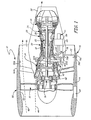
- FIG. 1 is a schematic cross-sectional side view of a gas turbine engine.
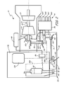
- FIG. 2 is a schematic side view of the gas turbine engine of FIG. 1 , showing a lubrication system.
- FIG. 3 is a partial schematic view of gear systems used in the gas turbine engine of FIG. 1 .
- FIG. 1 is a schematic cross-sectional side view of gas turbine engine 10.
- Gas turbine engine 10 is a turbofan engine and includes low pressure spool 12 (which includes low pressure compressor 14 and low pressure turbine 16 connected by low pressure shaft 18), high pressure spool 20 (which includes high pressure compressor 22 and high pressure turbine 24 connected by high pressure shaft 26), combustor 28, core cowling 30, fan 32, and fan shaft 34.
- low pressure spool 12 is coupled to fan shaft 34 via fan drive gear system 36 (which includes star gear 38, ring gear 40, and sun gear 42).
- Sun gear 42 is attached to and rotates with low pressure shaft 18.
- Ring gear 40 is rigidly connected to fan shaft 34 which turns at the same speed as fan 32.
- Star gear 38 is coupled between sun gear 42 and ring gear 40 such that star gear 38 revolves around sun gear 42 when sun gear 42 rotates.
- fan drive gear system 36 causes fan shaft 34 to rotate at a slower rotational velocity than that of low pressure spool 12.
- fan 32 can be connected to low pressure spool 12 in a manner other than by fan drive gear system 36.
- Fan bypass 46 is bounded at its inner diameter (ID) by core cowling 30 and at its outer diameter (OD) by fan case 50.
- Fan nacelle 52 has radially outer surface 52A and radially inner surface 52B. Fan nacelle 52 is positioned on fan case 50, with fan case 50 being part of radially inner surface 52B.
- Main accessory gearbox 54 is connected to high pressure spool 20 via gear system 56.
- Gear system 56 includes tower shaft 58, lay shaft 60, and bevel gears 62A-62D.
- Bevel gear 62A is fixedly connected to high pressure shaft 26.
- Bevel gears 62B and 62C are fixedly connected at opposite ends of tower shaft 58.
- Bevel gear 62D is fixedly connected to lay shaft 60.
- Bevel gear 62A is coupled to bevel gear 62B and bevel gear 62C is coupled to bevel gear 62D such that high pressure shaft 20 drives main accessory gearbox 54 when high pressure spool 20 rotates.
- Scavenge pump 64 and other accessories 66 are mounted to and driven by main accessory gearbox 54.
- Fan bypass 46 is positioned between main accessory gearbox 54 and second accessory gearbox 68.
- Second accessory gearbox 68 is connected to scavenge pump 64, and consequently to main accessory gearbox 54, via gear system 70.
- Gear system 70 includes tower shaft 72, lay shaft 74, and bevel gears 76A-76D.
- Bevel gear 76A is fixedly connected to scavenge pump shaft 78.
- Bevel gears 76B and 76C are fixedly connected at opposite ends of tower shaft 72.
- Bevel gear 76D is fixedly connected to lay shaft 74.
- Bevel gear 76A is coupled to bevel gear 76B and bevel gear 76C is coupled to bevel gear 76D such that scavenge pump 64 drives second accessory gearbox 68 when scavenge pump 64 rotates. Additional accessories are mounted to second accessory gearbox 68, as further described with respect to FIG. 2 .
- FIG. 2 is a schematic side view of gas turbine engine 10, showing lubrication system 80.
- Lubrication system 80 includes scavenge pump 64, supply pump 82, oil tank 84, filter 86, heat exchanger 88, all connected by lubrication circuit 90, and deoiler 92.
- Lubrication system 80 supplies lubricating liquid to and scavenges lubricating liquid from various gas turbine engine components, such as bearing compartment 94 and supply pump 82 itself. Though not illustrated for simplicity, lubrication system 80 can supply lubricating liquid to virtually any gas turbine engine component that benefits from lubricating liquid, such as those having gears and bearings.
- Supply pump 82 is a pressure oil pump mounted to and driven by second accessory gearbox 68.
- Supply pump 82 receives lubricating liquid from oil tank 84 and supplies that lubricating liquid through filter 86, through heat exchanger 88, and to bearing compartment 94 where it lubricates and cools bearings (not shown) that support high pressure shaft 26. Air from inside core cowling 30 (shown in FIG. 1 ) can also leak into bearing compartment 94.
- Scavenge pump 64 scavenges a mixture of lubricating liquid and air from bearing compartment 94 and returns it to oil tank 84. When the mixture of lubricating liquid and air is returned to oil tank 84, it is first passed through deaerator 96 to separate the air from the lubricating liquid.
- Lubricating liquid remains in oil tank 84 while the separated air is delivered to deoiler 92 via vent passage 98A.
- Deoiler 92 is positioned in second accessory gearbox 68. Deoiler 92 further separates lubricating liquid from air and vents the separated air overboard to atmosphere. Air from main accessory gearbox 54 is vented to second accessory gearbox 68 via vent passage 98B, then to deoiler 92, and then overboard to atmosphere.
- supply pump 82 has its own gears and bearings (not shown), it too requires lubricating liquid to lubricate those gears and bearings.
- Supply pump 82 has a small scavenge element 100 which scavenges lubricating liquid from supply pump 82 and returns it to oil tank 84.
- Permanent magnet generator 102 is also mounted to and driven by second accessory gearbox 68.
- Electronic engine controller 104 is powered by permanent magnet generator 102.
- each of supply pump 82, oil tank 84, filter 86, deoiler 92, permanent magnet generator 102, and electronic engine controller 104 are positioned on fan case 50, substantially inside fan nacelle 52 (shown in FIG. 1 ), allowing for relatively easy access to each for repair and maintenance.
- more or fewer components can be mounted on fan case 50.
- Accessories 66 include generator 66A, fuel pump 66B, hydraulic pump 66C, and starter 66D all connected to and driven by main accessory gearbox 54.
- Accessories 66 are all mounted to main accessory gearbox 54 and positioned radially inside core cowling 30 (shown in FIG. 1 ).
- accessories 66 can differ from those illustrated.
- generator 66A and starter 66D can be combined as a starter/generator.
- Second accessory gearbox 68 is smaller than main accessory gearbox 54.
- accessories mounted to second accessory gearbox 68 are generally smaller than some of the relatively large accessories 66 mounted to main accessory gearbox 54 (such as generator 66A, fuel pump 66B, hydraulic pump 66C, and starter 66D). This allows for fan nacelle 52 to house second accessory gearbox 68 while retaining a relatively small profile and having a relatively limited amount of fan nacelle drag during flight.
- scavenge pump 64 When lubrication system 80 is operating normally, rotation of scavenge pump 64 drives gear system 70, which drives second accessory gearbox 68, which drives supply pump 82 to supply lubricating liquid to bearing compartment 94 and other components. If scavenge pump 64 fails, stopping rotation of scavenge pump shaft 78, then supply pump 82 will also stop rotating. It can be undesirable to supply lubricating liquid to components when there is no scavenge pump operational to scavenge the lubricating liquid from the components. Allowing lubricating liquid to build up can be dangerous and harmful to gas turbine engine 10. Thus, this arrangement can create a fail-safe situation which prevents supply pump 82 from operating except when scavenge pump 64 is also operating.
- FIG. 3 is a partial schematic view of gear systems 56 and 70.
- FIG. 3 illustrates in greater detail one embodiment of gear systems 56 and 70 connecting to main accessory gearbox 54 and second accessory gearbox 68.
- shafts 58, 60, 72, and 74 as well as bevel gears 62A-62D and 76A-76D can be sized and shaped in a matter suitable for each of their respective connections.
- gear systems 56 and 70 can be varied as necessary for a particular application.
- main accessory gearbox 54 being positioned inside core cowling 30 and second accessory gearbox 68 being positioned outside of core cowling 30 on fan case 50.
- This allows for certain accessories to be positioned inside core cowling 30 while other accessories are positioned in fan nacelle 52.
- Accessories that benefit from being positioned in a relatively cool environment can be positioned in the nacelle.
- accessories that benefit from being positioned in a location suitable for relatively easy access by service personnel can also be positioned in the nacelle.
- Accessories that are relatively large and/or have relatively large power requirements can be positioned inside the core cowling on main accessory gearbox 54.
- lubrication circuits 90 need not be connected precisely as illustrated in FIG. 2 but can be modified as necessary for particular applications.
- lubrication system 80 can include one or more additional pumps, valves, filters, sensors, or other components.
- scavenge pump 64 need not necessarily be mounted directly to main accessory gearbox 54 as illustrated, so long as it is connected between main accessory gearbox 54 and second accessory gearbox 68.
Landscapes
- Engineering & Computer Science (AREA)
- Mechanical Engineering (AREA)
- General Engineering & Computer Science (AREA)
- Chemical & Material Sciences (AREA)
- Combustion & Propulsion (AREA)
- Lubrication Of Internal Combustion Engines (AREA)
- Control Of Turbines (AREA)
Abstract
Description
- The present invention relates to gas turbine engines, and in particular, to accessory drive systems on gas turbine engines.
- In gas turbine engines, an accessory gearbox is typically used to drive one or more accessories. In some gas turbine engines, the accessory gearbox is positioned inside of a core cowling. However, inside the core cowling is typically a relatively hot environment, which can damage and/or negatively affect the operation of certain accessories positioned inside the core cowling. Moreover, it can be difficult to access accessories inside the core cowling for service, which is undesirable for accessories that require frequent service. In other gas turbine engines, the accessory gearbox is positioned outside of the core cowling, such as in a fan nacelle. However, the accessory gearbox and certain accessories mounted to the gearbox can be relatively large. This can cause the fan nacelle to also be undesirably large, and thus undesirably increase fan nacelle drag.
- According to the present invention, a gas turbine engine includes a spool, a first accessory gearbox, a second accessory gearbox, and a scavenge pump. The first accessory gearbox is connected to and driven by the spool. The second accessory gearbox is connected to and driven by the first accessory gearbox. The scavenge pump is connected between the first accessory gearbox and the second accessory gearbox. The first accessory gearbox drives the second accessory gearbox through the scavenge pump.
- Another aspect of the present invention is a method for driving accessories on a gas turbine engine. The method includes driving a scavenge pump via a first accessory gearbox, driving a second accessory gearbox via the scavenge pump, and driving a supply pump via the second accessory gearbox.
-
FIG. 1 is a schematic cross-sectional side view of a gas turbine engine. -
FIG. 2 is a schematic side view of the gas turbine engine ofFIG. 1 , showing a lubrication system. -
FIG. 3 is a partial schematic view of gear systems used in the gas turbine engine ofFIG. 1 . -
FIG. 1 is a schematic cross-sectional side view ofgas turbine engine 10.Gas turbine engine 10 is a turbofan engine and includes low pressure spool 12 (which includeslow pressure compressor 14 andlow pressure turbine 16 connected by low pressure shaft 18), high pressure spool 20 (which includeshigh pressure compressor 22 andhigh pressure turbine 24 connected by high pressure shaft 26),combustor 28,core cowling 30,fan 32, andfan shaft 34. In the embodiment shown inFIG. 1 ,low pressure spool 12 is coupled tofan shaft 34 via fan drive gear system 36 (which includesstar gear 38,ring gear 40, and sun gear 42). Sungear 42 is attached to and rotates withlow pressure shaft 18.Ring gear 40 is rigidly connected tofan shaft 34 which turns at the same speed asfan 32. Stargear 38 is coupled betweensun gear 42 andring gear 40 such thatstar gear 38 revolves aroundsun gear 42 whensun gear 42 rotates. Whenlow pressure spool 12 rotates, fandrive gear system 36 causesfan shaft 34 to rotate at a slower rotational velocity than that oflow pressure spool 12. In alternative embodiments,fan 32 can be connected tolow pressure spool 12 in a manner other than by fandrive gear system 36. - Air flows from
fan 32, throughlow pressure compressor 14,high pressure compressor 22,combustor 28,high pressure turbine 24, andlow pressure turbine 16 alongmain flow path 44. Air also flows fromfan 32 throughfan bypass 46 alongbypass flow path 48.Fan bypass 46 is bounded at its inner diameter (ID) by core cowling 30 and at its outer diameter (OD) byfan case 50.Fan nacelle 52 has radiallyouter surface 52A and radiallyinner surface 52B.Fan nacelle 52 is positioned onfan case 50, withfan case 50 being part of radiallyinner surface 52B. -
Main accessory gearbox 54 is connected tohigh pressure spool 20 viagear system 56.Gear system 56 includestower shaft 58,lay shaft 60, andbevel gears 62A-62D.Bevel gear 62A is fixedly connected tohigh pressure shaft 26.Bevel gears tower shaft 58.Bevel gear 62D is fixedly connected tolay shaft 60.Bevel gear 62A is coupled tobevel gear 62B andbevel gear 62C is coupled tobevel gear 62D such thathigh pressure shaft 20 drivesmain accessory gearbox 54 whenhigh pressure spool 20 rotates.Scavenge pump 64 andother accessories 66 are mounted to and driven bymain accessory gearbox 54.Fan bypass 46 is positioned betweenmain accessory gearbox 54 andsecond accessory gearbox 68. - Second accessory gearbox 68 is connected to
scavenge pump 64, and consequently to mainaccessory gearbox 54, viagear system 70.Gear system 70 includestower shaft 72,lay shaft 74, andbevel gears 76A-76D.Bevel gear 76A is fixedly connected toscavenge pump shaft 78.Bevel gears tower shaft 72.Bevel gear 76D is fixedly connected tolay shaft 74.Bevel gear 76A is coupled tobevel gear 76B andbevel gear 76C is coupled tobevel gear 76D such thatscavenge pump 64 drivessecond accessory gearbox 68 whenscavenge pump 64 rotates. Additional accessories are mounted tosecond accessory gearbox 68, as further described with respect toFIG. 2 . -
FIG. 2 is a schematic side view ofgas turbine engine 10, showinglubrication system 80.Lubrication system 80 includesscavenge pump 64,supply pump 82,oil tank 84,filter 86,heat exchanger 88, all connected bylubrication circuit 90, anddeoiler 92.Lubrication system 80 supplies lubricating liquid to and scavenges lubricating liquid from various gas turbine engine components, such asbearing compartment 94 andsupply pump 82 itself. Though not illustrated for simplicity,lubrication system 80 can supply lubricating liquid to virtually any gas turbine engine component that benefits from lubricating liquid, such as those having gears and bearings. -
Supply pump 82 is a pressure oil pump mounted to and driven bysecond accessory gearbox 68.Supply pump 82 receives lubricating liquid fromoil tank 84 and supplies that lubricating liquid throughfilter 86, throughheat exchanger 88, and to bearingcompartment 94 where it lubricates and cools bearings (not shown) that supporthigh pressure shaft 26. Air from inside core cowling 30 (shown inFIG. 1 ) can also leak intobearing compartment 94.Scavenge pump 64 scavenges a mixture of lubricating liquid and air frombearing compartment 94 and returns it tooil tank 84. When the mixture of lubricating liquid and air is returned tooil tank 84, it is first passed through deaerator 96 to separate the air from the lubricating liquid. Lubricating liquid remains inoil tank 84 while the separated air is delivered todeoiler 92 viavent passage 98A. Deoiler 92 is positioned insecond accessory gearbox 68. Deoiler 92 further separates lubricating liquid from air and vents the separated air overboard to atmosphere. Air from main accessory gearbox 54 is vented tosecond accessory gearbox 68 viavent passage 98B, then to deoiler 92, and then overboard to atmosphere. - Because
supply pump 82 has its own gears and bearings (not shown), it too requires lubricating liquid to lubricate those gears and bearings.Supply pump 82 has asmall scavenge element 100 which scavenges lubricating liquid fromsupply pump 82 and returns it tooil tank 84. -
Permanent magnet generator 102 is also mounted to and driven bysecond accessory gearbox 68.Electronic engine controller 104 is powered bypermanent magnet generator 102. Like secondaccessory gearbox 68, each ofsupply pump 82,oil tank 84,filter 86,deoiler 92,permanent magnet generator 102, andelectronic engine controller 104 are positioned onfan case 50, substantially inside fan nacelle 52 (shown inFIG. 1 ), allowing for relatively easy access to each for repair and maintenance. In alternative embodiments, more or fewer components can be mounted onfan case 50. -
Accessories 66 includegenerator 66A,fuel pump 66B,hydraulic pump 66C, andstarter 66D all connected to and driven by mainaccessory gearbox 54.Accessories 66 are all mounted to mainaccessory gearbox 54 and positioned radially inside core cowling 30 (shown inFIG. 1 ). In alternative embodiments,accessories 66 can differ from those illustrated. For example,generator 66A andstarter 66D can be combined as a starter/generator.Second accessory gearbox 68 is smaller than mainaccessory gearbox 54. Similarly, accessories mounted to second accessory gearbox 68 (such assupply pump 82 and permanent magnet generator 102) are generally smaller than some of the relativelylarge accessories 66 mounted to main accessory gearbox 54 (such asgenerator 66A,fuel pump 66B,hydraulic pump 66C, andstarter 66D). This allows forfan nacelle 52 to housesecond accessory gearbox 68 while retaining a relatively small profile and having a relatively limited amount of fan nacelle drag during flight. - When
lubrication system 80 is operating normally, rotation ofscavenge pump 64drives gear system 70, which drives secondaccessory gearbox 68, which drivessupply pump 82 to supply lubricating liquid to bearingcompartment 94 and other components. If scavenge pump 64 fails, stopping rotation ofscavenge pump shaft 78, then supplypump 82 will also stop rotating. It can be undesirable to supply lubricating liquid to components when there is no scavenge pump operational to scavenge the lubricating liquid from the components. Allowing lubricating liquid to build up can be dangerous and harmful togas turbine engine 10. Thus, this arrangement can create a fail-safe situation which preventssupply pump 82 from operating except when scavenge pump 64 is also operating. -
FIG. 3 is a partial schematic view ofgear systems FIG. 3 illustrates in greater detail one embodiment ofgear systems accessory gearbox 54 and secondaccessory gearbox 68. As shown,shafts bevel gears 62A-62D and 76A-76D can be sized and shaped in a matter suitable for each of their respective connections. In alternative embodiments,gear systems - Thus, the systems described above allow for two accessory gearboxes to be located in different parts of gas turbine engine 10: main
accessory gearbox 54 being positioned insidecore cowling 30 and secondaccessory gearbox 68 being positioned outside ofcore cowling 30 onfan case 50. This allows for certain accessories to be positioned insidecore cowling 30 while other accessories are positioned infan nacelle 52. Accessories that benefit from being positioned in a relatively cool environment can be positioned in the nacelle. Similarly, accessories that benefit from being positioned in a location suitable for relatively easy access by service personnel can also be positioned in the nacelle. Accessories that are relatively large and/or have relatively large power requirements can be positioned inside the core cowling on mainaccessory gearbox 54. By connectingscavenge pump 64 between mainaccessory gearbox 54 and secondaccessory gearbox 68,lubrication system 80 can fail-safe in the event of a failure ofscavenge pump 64. - While the invention has been described with reference to exemplary embodiments, it will be understood by those skilled in the art that various changes may be made and equivalents may be substituted for elements thereof without departing from the scope of the invention, which is defined by the claims. In addition, many modifications may be made to adapt a particular situation or material to the teachings of the invention without departing from the essential scope thereof. Therefore, it is intended that the invention not be limited to the particular embodiments disclosed, but that the invention will include all embodiments falling within the scope of the appended claims. For example,
lubrication circuits 90 need not be connected precisely as illustrated inFIG. 2 but can be modified as necessary for particular applications. Similarly,lubrication system 80 can include one or more additional pumps, valves, filters, sensors, or other components. Moreover, scavengepump 64 need not necessarily be mounted directly to mainaccessory gearbox 54 as illustrated, so long as it is connected between mainaccessory gearbox 54 and secondaccessory gearbox 68.
Claims (15)
- A gas turbine engine (10) comprising:a spool (20);a first accessory gearbox (54) connected to and driven by the spool;a second accessory gearbox (68) connected to and driven by the first accessory gearbox; anda scavenge pump (64) connected between the first accessory gearbox and the second accessory gearbox, wherein the first accessory gearbox drives the second accessory gearbox through the scavenge pump.
- The gas turbine engine of claim 1, wherein the first accessory gearbox is positioned substantially inside a core cowling (30) and wherein the second accessory gearbox is positioned substantially outside of the core cowling; preferably
wherein the second accessory gearbox is positioned on a fan case (50); more preferably
wherein the second accessory gearbox is positioned within a nacelle (52) on the fan case. - The gas turbine engine of claim 1 or 2, and further comprising:a supply pump (82) connected to and driven by the second accessory gearbox;an oil tank (84) positioned on the fan case;an oil filter (86) positioned on the fan case; anda lubrication circuit (80) connecting the scavenge pump, the supply pump, the oil tank, and the oil filter.
- The gas turbine engine of claim 1, 2 or 3, and further comprising:a generator (66A) connected to and driven by the first accessory gearbox;a fuel pump (66B) connected to and driven by the first accessory gearbox;a hydraulic pump (66C) connected to and driven by the first accessory gearbox; anda starter (66D) connected to and driven by the first accessory gearbox.
- The gas turbine engine of any preceding claim, and further comprising:a permanent magnet generator (102) connected to and driven by the second accessory gearbox; andan electronic engine controller (104) powered by the permanent magnet generator and positioned on a fan case.
- The gas turbine engine of any preceding claim, wherein the scavenge pump is mounted to the first accessory gearbox.
- The gas turbine engine of any preceding claim, and further comprising:a first gear system (56) connecting the spool to the first accessory gearbox; anda second gear system (70) connecting the scavenge pump to the second accessory gearbox; preferablywherein the second gear system comprises:a first bevel gear (76A) connected to a shaft (78) of the scavenge pump;a tower shaft (72) having second (76B) and third (76C) bevel gears, wherein the second bevel gear is connected to the first bevel gear; anda lay shaft (74) having a fourth bevel gear (76D) connected to the third bevel gear, wherein the lay shaft is connected to and drives the second accessory gearbox.
- The gas turbine engine of any preceding claim, wherein the gas turbine engine is a turbofan engine, and further comprising:a fan bypass (46) positioned between the first accessory gearbox and the second accessory gearbox; and/orwherein the second accessory gearbox is smaller than the first accessory gearbox.
- A method for driving accessories on a gas turbine engine (10), the method comprising:driving a scavenge pump (64) via a first accessory gearbox (54);driving a second accessory gearbox (68) via the scavenge pump; anddriving a supply pump (82) via the second accessory gearbox.
- The method of claim 9, wherein the first accessory gearbox is connected to and driven by a spool (20) of the gas turbine engine via a first gear system (56) and wherein the second accessory gearbox is connected to and driven by the scavenge pump via a second gear system (70).
- The method of claim 9 or 10, wherein the second accessory gearbox fails to drive the supply pump in response to a failure of the scavenge pump.
- The method of claim 9, 10 or 11, and further comprising:pumping lubricating liquid to a plurality of gas turbine engine components via the supply pump; andscavenging lubricating liquid from the plurality of gas turbine engine components via the scavenge pump.
- The method of claim 9, 10, 11 or 12, and further comprising:driving a generator (66A), a fuel pump (66B), a hydraulic pump (66C), and a starter (66D) via the first accessory gearbox; anddriving a permanent magnet generator (102) via the second accessory gearbox.
- The method of any of claims 9 to 13, wherein the scavenge pump is mounted to the first accessory gearbox.
- The method of any of claims 9 to 14, and further comprising:venting air from the first accessory gearbox to the second accessory gearbox; preferably further comprising:venting air from the second accessory gearbox through a deoiler (92) positioned on the second accessory gearbox.
Applications Claiming Priority (1)
| Application Number | Priority Date | Filing Date | Title |
|---|---|---|---|
| US13/276,838 US9062611B2 (en) | 2011-10-19 | 2011-10-19 | Split accessory drive system |
Publications (3)
| Publication Number | Publication Date |
|---|---|
| EP2584171A2 true EP2584171A2 (en) | 2013-04-24 |
| EP2584171A3 EP2584171A3 (en) | 2017-04-19 |
| EP2584171B1 EP2584171B1 (en) | 2018-10-17 |
Family
ID=46800080
Family Applications (1)
| Application Number | Title | Priority Date | Filing Date |
|---|---|---|---|
| EP12182349.6A Active EP2584171B1 (en) | 2011-10-19 | 2012-08-30 | Split accessory drive system |
Country Status (2)
| Country | Link |
|---|---|
| US (1) | US9062611B2 (en) |
| EP (1) | EP2584171B1 (en) |
Cited By (2)
| Publication number | Priority date | Publication date | Assignee | Title |
|---|---|---|---|---|
| EP2900979A4 (en) * | 2012-09-28 | 2015-10-21 | United Technologies Corp | Geared turbofan with fan and core mounted accessory gearboxes |
| EP3060779A4 (en) * | 2013-10-24 | 2017-07-26 | United Technologies Corporation | Gas turbine lubrication systems |
Families Citing this family (49)
| Publication number | Priority date | Publication date | Assignee | Title |
|---|---|---|---|---|
| US9719428B2 (en) * | 2007-11-30 | 2017-08-01 | United Technologies Corporation | Gas turbine engine with pylon mounted accessory drive |
| JP5568596B2 (en) * | 2012-05-30 | 2014-08-06 | 川崎重工業株式会社 | Aircraft engine gearbox integrated power generator |
| US9297314B2 (en) * | 2012-12-19 | 2016-03-29 | United Technologies Corporation | Gas turbine engine with accessory gear box |
| WO2014130239A2 (en) * | 2013-02-25 | 2014-08-28 | United Technologies Corporation | Auxiliary lubricant supply pump stage integral with main lubricant pump stage |
| US9752500B2 (en) * | 2013-03-14 | 2017-09-05 | Pratt & Whitney Canada Corp. | Gas turbine engine with transmission and method of adjusting rotational speed |
| EP3004564A4 (en) * | 2013-06-07 | 2016-11-23 | Ge Aviat Systems Llc | Turbofan engine with generator |
| FR3007458B1 (en) * | 2013-06-21 | 2017-11-10 | Snecma | IMPROVED TURBOMACHINE INTERMEDIATE CASE AND ACCESSORY BOX DRIVE ASSEMBLY |
| WO2015065720A1 (en) * | 2013-11-01 | 2015-05-07 | United Technologies Corporation | Auxiliary oil pump for gas turbine engine gear reduction |
| FR3016408B1 (en) * | 2014-01-16 | 2019-05-31 | Safran Transmission Systems | ACCESSORY TRAINING ASSEMBLY FOR AIRCRAFT TURBINE ENGINE |
| US10634061B2 (en) * | 2014-03-06 | 2020-04-28 | United Technologies Corporation | Gas turbine engine accessory architecture |
| US9849411B2 (en) | 2014-05-28 | 2017-12-26 | United Technologies Corporation | Scavenge filter system for a gas turbine engine |
| US9611787B2 (en) | 2015-05-18 | 2017-04-04 | General Electric Company | Accessory apparatus and method of assembling accessories with a turbine engine |
| US10578017B2 (en) | 2015-06-23 | 2020-03-03 | United Technologies Corporation | Windmill and negative-G oil system for geared turbofan engines |
| FR3040692B1 (en) * | 2015-09-04 | 2017-08-25 | Snecma | OIL COOLER INTEGRATED WITH PYLON |
| US10072582B2 (en) * | 2016-04-28 | 2018-09-11 | General Electric Company | Integral offset oil tank for inline accessory gearbox |
| US20170362959A1 (en) * | 2016-06-20 | 2017-12-21 | United Technologies Corporation | Lubrication system with multiple lubrication circuits |
| US11415063B2 (en) * | 2016-09-15 | 2022-08-16 | Pratt & Whitney Canada Corp. | Reverse-flow gas turbine engine |
| US10883424B2 (en) | 2016-07-19 | 2021-01-05 | Pratt & Whitney Canada Corp. | Multi-spool gas turbine engine architecture |
| US11035293B2 (en) | 2016-09-15 | 2021-06-15 | Pratt & Whitney Canada Corp. | Reverse flow gas turbine engine with offset RGB |
| US10465611B2 (en) * | 2016-09-15 | 2019-11-05 | Pratt & Whitney Canada Corp. | Reverse flow multi-spool gas turbine engine with aft-end accessory gearbox drivingly connected to both high pressure spool and low pressure spool |
| US10815899B2 (en) | 2016-11-15 | 2020-10-27 | Pratt & Whitney Canada Corp. | Gas turbine engine accessories arrangement |
| US20180171815A1 (en) * | 2016-12-16 | 2018-06-21 | United Technologies Corporation | Traction drive transmission for gas turbine engine accessory gearbox |
| US10808624B2 (en) | 2017-02-09 | 2020-10-20 | Pratt & Whitney Canada Corp. | Turbine rotor with low over-speed requirements |
| US10738709B2 (en) | 2017-02-09 | 2020-08-11 | Pratt & Whitney Canada Corp. | Multi-spool gas turbine engine |
| US10746188B2 (en) | 2017-03-14 | 2020-08-18 | Pratt & Whitney Canada Corp. | Inter-shaft bearing connected to a compressor boost system |
| US10215052B2 (en) | 2017-03-14 | 2019-02-26 | Pratt & Whitney Canada Corp. | Inter-shaft bearing arrangement |
| US20180283281A1 (en) * | 2017-03-31 | 2018-10-04 | Hamilton Sundstrand Corporation | Accessory gearboxes |
| US10823080B2 (en) * | 2017-05-31 | 2020-11-03 | General Electric Company | Dual accessory gearbox |
| US10731566B2 (en) * | 2017-10-18 | 2020-08-04 | Honeywell International Inc. | Compact accessory systems for a gas turbine engine |
| US11168585B2 (en) * | 2018-01-08 | 2021-11-09 | Raytheon Technologies Corporation | Geared gas turbine engine with improved breather air venting |
| US11073053B2 (en) | 2018-05-08 | 2021-07-27 | Raytheon Technologies Corporation | Centrifugal debris pre-separator for turbine engine oil filter |
| EP4339440A3 (en) | 2018-08-08 | 2024-05-22 | Pratt & Whitney Canada Corp. | Multi-engine system and method |
| US20200080476A1 (en) * | 2018-09-12 | 2020-03-12 | Pratt & Whitney Canada Corp. | Spilt compressor system on multi-spool engine |
| US11485503B2 (en) * | 2019-03-29 | 2022-11-01 | Pratt & Whitney Canada Corp. | Hybrid aircraft propulsion power plants |
| US11408345B2 (en) * | 2019-08-29 | 2022-08-09 | Rolls-Royce Corporation | Oil tank for geared turbofan engine |
| US11428168B2 (en) * | 2020-01-06 | 2022-08-30 | Hamilton Sundstrand Corporation | Starter/generator arrangements for gas turbine engines |
| US11408340B2 (en) * | 2020-05-15 | 2022-08-09 | Pratt & Whitney Canada Corp. | Twin-engine system with electric drive |
| DE102020117255A1 (en) | 2020-06-30 | 2021-12-30 | Rolls-Royce Deutschland Ltd & Co Kg | Gas turbine engine and aircraft with a gas turbine engine |
| DE102020117254A1 (en) | 2020-06-30 | 2021-12-30 | Rolls-Royce Deutschland Ltd & Co Kg | Gas turbine engine and aircraft with a gas turbine engine |
| US11788427B2 (en) | 2021-06-10 | 2023-10-17 | Pratt & Whitney Canada Corp. | Lubricant pump system and method for aircraft engine |
| US11814968B2 (en) * | 2021-07-19 | 2023-11-14 | Rtx Corporation | Gas turbine engine with idle thrust ratio |
| US20240218835A1 (en) * | 2023-01-04 | 2024-07-04 | General Electric Company | Outlet guide vanes and an accessory drive gearbox for a gas turbine engine |
| US12215629B2 (en) * | 2023-02-06 | 2025-02-04 | General Electric Company | Turbine engine including transfer gearbox and accessory gearbox |
| US20250075662A1 (en) * | 2023-09-05 | 2025-03-06 | General Electric Company | Turbine Engine having First and Second Accessory Gearboxes |
| US20250154906A1 (en) * | 2023-11-13 | 2025-05-15 | Rtx Corporation | Turbine engine accessory system with multiple gearboxes |
| US12209557B1 (en) * | 2023-11-30 | 2025-01-28 | General Electric Company | Gas turbine engine with forward swept outlet guide vanes |
| US12352179B1 (en) | 2024-07-24 | 2025-07-08 | General Electric Company | Turbine engine including a lubrication system |
| US12372032B1 (en) * | 2024-08-01 | 2025-07-29 | Rtx Corporation | Gas turbine engine with controlled return of fuel to power accessories and retrofitting method |
| US20260071575A1 (en) * | 2024-09-10 | 2026-03-12 | General Electric Company | Propulsion system including a turbine engine |
Family Cites Families (19)
| Publication number | Priority date | Publication date | Assignee | Title |
|---|---|---|---|---|
| US4722666A (en) | 1987-06-29 | 1988-02-02 | United Technologies Corporation | Nose cowl mounted oil lubricating and cooling system |
| GB9313905D0 (en) * | 1993-07-06 | 1993-08-25 | Rolls Royce Plc | Shaft power transfer in gas turbine engines |
| GB9910393D0 (en) * | 1999-05-05 | 1999-07-07 | Lucas Ind Plc | Electrical generator,an aero-engine including such a generator and an aircraft including such a generator |
| JP2001317376A (en) * | 2000-04-28 | 2001-11-16 | Honda Motor Co Ltd | Auxiliary drive unit for gas turbine engine |
| GB0315894D0 (en) * | 2003-07-08 | 2003-08-13 | Rolls Royce Plc | Aircraft engine arrangement |
| US7377110B2 (en) | 2004-03-31 | 2008-05-27 | United Technologies Corporation | Deoiler for a lubrication system |
| GB0422241D0 (en) * | 2004-10-07 | 2004-11-10 | Rolls Royce Plc | Aeroengine oil tank fire protection system |
| US7805947B2 (en) | 2005-05-19 | 2010-10-05 | Djamal Moulebhar | Aircraft with disengageable engine and auxiliary power unit components |
| US8485222B2 (en) * | 2007-01-31 | 2013-07-16 | Honeywell International Inc. | Systems and methods for preventing oil migration |
| GB0714924D0 (en) * | 2007-08-01 | 2007-09-12 | Rolls Royce Plc | An engine arrangement |
| US8333554B2 (en) | 2007-11-14 | 2012-12-18 | United Technologies Corporation | Split gearbox and nacelle arrangement |
| GB0805177D0 (en) * | 2008-03-20 | 2008-04-30 | Rolls Royce Plc | A gas turbine engine arrangement |
| GB0823085D0 (en) * | 2008-12-19 | 2009-01-28 | Rolls Royce Plc | Combustor Rumble |
| US9816441B2 (en) * | 2009-03-30 | 2017-11-14 | United Technologies Corporation | Gas turbine engine with stacked accessory components |
| GB2472445B (en) * | 2009-08-07 | 2011-08-03 | Rolls Royce Plc | A propulsion unit |
| US8601785B2 (en) * | 2010-06-23 | 2013-12-10 | Pratt & Whitney Canada Corp. | Oil supply system with main pump deaeration |
| US8456051B2 (en) * | 2010-05-05 | 2013-06-04 | Oeco, Llc | High reliability generator with dual drive path |
| US8876933B2 (en) * | 2010-12-08 | 2014-11-04 | Hamilton Sundstrand Corporation | Core diffuser for deoiler/breather |
| US20140090386A1 (en) * | 2012-09-28 | 2014-04-03 | United Technologies Corporation | Geared turbofan with fan and core mounted accessory gearboxes |
-
2011
- 2011-10-19 US US13/276,838 patent/US9062611B2/en not_active Expired - Fee Related
-
2012
- 2012-08-30 EP EP12182349.6A patent/EP2584171B1/en active Active
Non-Patent Citations (1)
| Title |
|---|
| None |
Cited By (3)
| Publication number | Priority date | Publication date | Assignee | Title |
|---|---|---|---|---|
| EP2900979A4 (en) * | 2012-09-28 | 2015-10-21 | United Technologies Corp | Geared turbofan with fan and core mounted accessory gearboxes |
| EP3060779A4 (en) * | 2013-10-24 | 2017-07-26 | United Technologies Corporation | Gas turbine lubrication systems |
| US10082077B2 (en) | 2013-10-24 | 2018-09-25 | United Technologies Corporation | Gas turbine lubrication systems |
Also Published As
| Publication number | Publication date |
|---|---|
| EP2584171A3 (en) | 2017-04-19 |
| US20130098058A1 (en) | 2013-04-25 |
| US9062611B2 (en) | 2015-06-23 |
| EP2584171B1 (en) | 2018-10-17 |
Similar Documents
| Publication | Publication Date | Title |
|---|---|---|
| EP2584171B1 (en) | Split accessory drive system | |
| CN110185775B (en) | Passive lubrication system for gas turbine engine gearbox during wind turns | |
| US10711642B2 (en) | Gas turbine engine lubrication system and apparatus with boost pump system | |
| US10196926B2 (en) | Lubricating a rotating component during forward and/or reverse rotation | |
| EP3865735B1 (en) | Near zero velocity lubrication system for a turbine engine | |
| EP2971662B1 (en) | Circulating lubricant through a turbine engine component with parallel pumps | |
| US7500365B2 (en) | Accessory gearbox | |
| EP3495630B1 (en) | Pneumatic starter supplemental lubrication system | |
| EP3282093A1 (en) | Geared turbofan with low spool power extraction | |
| EP3095974A1 (en) | Lubrication system for a gas turbine engine | |
| US9897010B2 (en) | Air turbine starter systems including gearbox-integrated clutch modules and gas turbine engines employing the same | |
| RU2594058C2 (en) | Non-lubricated structure for turbo shaft engine | |
| GB2536847A (en) | Supply of air to an air-conditioning circuit of an aircraft cabin from its turboprop engine | |
| EP3260668A1 (en) | Lubrication system with multiple lubrication circuits | |
| CN108331903B (en) | Equipment for gearboxes with multiple drains | |
| US20250207510A1 (en) | Lubrication and cooling of equipment of an aircraft turbomachine | |
| CN121175482A (en) | Turbine engine comprising an accessory drive, a lubrication unit and an oil tank | |
| CA3256423A1 (en) | Lubrication system for an aircraft powerplant and clutch system |
Legal Events
| Date | Code | Title | Description |
|---|---|---|---|
| PUAI | Public reference made under article 153(3) epc to a published international application that has entered the european phase |
Free format text: ORIGINAL CODE: 0009012 |
|
| AK | Designated contracting states |
Kind code of ref document: A2 Designated state(s): AL AT BE BG CH CY CZ DE DK EE ES FI FR GB GR HR HU IE IS IT LI LT LU LV MC MK MT NL NO PL PT RO RS SE SI SK SM TR |
|
| AX | Request for extension of the european patent |
Extension state: BA ME |
|
| RAP1 | Party data changed (applicant data changed or rights of an application transferred) |
Owner name: UNITED TECHNOLOGIES CORPORATION |
|
| PUAL | Search report despatched |
Free format text: ORIGINAL CODE: 0009013 |
|
| AK | Designated contracting states |
Kind code of ref document: A3 Designated state(s): AL AT BE BG CH CY CZ DE DK EE ES FI FR GB GR HR HU IE IS IT LI LT LU LV MC MK MT NL NO PL PT RO RS SE SI SK SM TR |
|
| AX | Request for extension of the european patent |
Extension state: BA ME |
|
| RIC1 | Information provided on ipc code assigned before grant |
Ipc: F01D 25/18 20060101ALI20170313BHEP Ipc: F02C 7/32 20060101AFI20170313BHEP |
|
| STAA | Information on the status of an ep patent application or granted ep patent |
Free format text: STATUS: REQUEST FOR EXAMINATION WAS MADE |
|
| STAA | Information on the status of an ep patent application or granted ep patent |
Free format text: STATUS: EXAMINATION IS IN PROGRESS |
|
| 17P | Request for examination filed |
Effective date: 20171018 |
|
| RBV | Designated contracting states (corrected) |
Designated state(s): AL AT BE BG CH CY CZ DE DK EE ES FI FR GB GR HR HU IE IS IT LI LT LU LV MC MK MT NL NO PL PT RO RS SE SI SK SM TR |
|
| 17Q | First examination report despatched |
Effective date: 20171121 |
|
| GRAP | Despatch of communication of intention to grant a patent |
Free format text: ORIGINAL CODE: EPIDOSNIGR1 |
|
| STAA | Information on the status of an ep patent application or granted ep patent |
Free format text: STATUS: GRANT OF PATENT IS INTENDED |
|
| INTG | Intention to grant announced |
Effective date: 20180514 |
|
| GRAS | Grant fee paid |
Free format text: ORIGINAL CODE: EPIDOSNIGR3 |
|
| GRAA | (expected) grant |
Free format text: ORIGINAL CODE: 0009210 |
|
| STAA | Information on the status of an ep patent application or granted ep patent |
Free format text: STATUS: THE PATENT HAS BEEN GRANTED |
|
| AK | Designated contracting states |
Kind code of ref document: B1 Designated state(s): AL AT BE BG CH CY CZ DE DK EE ES FI FR GB GR HR HU IE IS IT LI LT LU LV MC MK MT NL NO PL PT RO RS SE SI SK SM TR |
|
| REG | Reference to a national code |
Ref country code: GB Ref legal event code: FG4D |
|
| REG | Reference to a national code |
Ref country code: CH Ref legal event code: EP |
|
| REG | Reference to a national code |
Ref country code: IE Ref legal event code: FG4D |
|
| REG | Reference to a national code |
Ref country code: DE Ref legal event code: R096 Ref document number: 602012052254 Country of ref document: DE Ref country code: AT Ref legal event code: REF Ref document number: 1054313 Country of ref document: AT Kind code of ref document: T Effective date: 20181115 |
|
| REG | Reference to a national code |
Ref country code: NL Ref legal event code: MP Effective date: 20181017 |
|
| REG | Reference to a national code |
Ref country code: LT Ref legal event code: MG4D |
|
| REG | Reference to a national code |
Ref country code: AT Ref legal event code: MK05 Ref document number: 1054313 Country of ref document: AT Kind code of ref document: T Effective date: 20181017 |
|
| PG25 | Lapsed in a contracting state [announced via postgrant information from national office to epo] |
Ref country code: NL Free format text: LAPSE BECAUSE OF FAILURE TO SUBMIT A TRANSLATION OF THE DESCRIPTION OR TO PAY THE FEE WITHIN THE PRESCRIBED TIME-LIMIT Effective date: 20181017 |
|
| PG25 | Lapsed in a contracting state [announced via postgrant information from national office to epo] |
Ref country code: ES Free format text: LAPSE BECAUSE OF FAILURE TO SUBMIT A TRANSLATION OF THE DESCRIPTION OR TO PAY THE FEE WITHIN THE PRESCRIBED TIME-LIMIT Effective date: 20181017 Ref country code: HR Free format text: LAPSE BECAUSE OF FAILURE TO SUBMIT A TRANSLATION OF THE DESCRIPTION OR TO PAY THE FEE WITHIN THE PRESCRIBED TIME-LIMIT Effective date: 20181017 Ref country code: LV Free format text: LAPSE BECAUSE OF FAILURE TO SUBMIT A TRANSLATION OF THE DESCRIPTION OR TO PAY THE FEE WITHIN THE PRESCRIBED TIME-LIMIT Effective date: 20181017 Ref country code: FI Free format text: LAPSE BECAUSE OF FAILURE TO SUBMIT A TRANSLATION OF THE DESCRIPTION OR TO PAY THE FEE WITHIN THE PRESCRIBED TIME-LIMIT Effective date: 20181017 Ref country code: BG Free format text: LAPSE BECAUSE OF FAILURE TO SUBMIT A TRANSLATION OF THE DESCRIPTION OR TO PAY THE FEE WITHIN THE PRESCRIBED TIME-LIMIT Effective date: 20190117 Ref country code: PL Free format text: LAPSE BECAUSE OF FAILURE TO SUBMIT A TRANSLATION OF THE DESCRIPTION OR TO PAY THE FEE WITHIN THE PRESCRIBED TIME-LIMIT Effective date: 20181017 Ref country code: AT Free format text: LAPSE BECAUSE OF FAILURE TO SUBMIT A TRANSLATION OF THE DESCRIPTION OR TO PAY THE FEE WITHIN THE PRESCRIBED TIME-LIMIT Effective date: 20181017 Ref country code: LT Free format text: LAPSE BECAUSE OF FAILURE TO SUBMIT A TRANSLATION OF THE DESCRIPTION OR TO PAY THE FEE WITHIN THE PRESCRIBED TIME-LIMIT Effective date: 20181017 Ref country code: NO Free format text: LAPSE BECAUSE OF FAILURE TO SUBMIT A TRANSLATION OF THE DESCRIPTION OR TO PAY THE FEE WITHIN THE PRESCRIBED TIME-LIMIT Effective date: 20190117 Ref country code: IS Free format text: LAPSE BECAUSE OF FAILURE TO SUBMIT A TRANSLATION OF THE DESCRIPTION OR TO PAY THE FEE WITHIN THE PRESCRIBED TIME-LIMIT Effective date: 20190217 |
|
| PG25 | Lapsed in a contracting state [announced via postgrant information from national office to epo] |
Ref country code: RS Free format text: LAPSE BECAUSE OF FAILURE TO SUBMIT A TRANSLATION OF THE DESCRIPTION OR TO PAY THE FEE WITHIN THE PRESCRIBED TIME-LIMIT Effective date: 20181017 Ref country code: GR Free format text: LAPSE BECAUSE OF FAILURE TO SUBMIT A TRANSLATION OF THE DESCRIPTION OR TO PAY THE FEE WITHIN THE PRESCRIBED TIME-LIMIT Effective date: 20190118 Ref country code: PT Free format text: LAPSE BECAUSE OF FAILURE TO SUBMIT A TRANSLATION OF THE DESCRIPTION OR TO PAY THE FEE WITHIN THE PRESCRIBED TIME-LIMIT Effective date: 20190217 Ref country code: AL Free format text: LAPSE BECAUSE OF FAILURE TO SUBMIT A TRANSLATION OF THE DESCRIPTION OR TO PAY THE FEE WITHIN THE PRESCRIBED TIME-LIMIT Effective date: 20181017 Ref country code: SE Free format text: LAPSE BECAUSE OF FAILURE TO SUBMIT A TRANSLATION OF THE DESCRIPTION OR TO PAY THE FEE WITHIN THE PRESCRIBED TIME-LIMIT Effective date: 20181017 |
|
| REG | Reference to a national code |
Ref country code: DE Ref legal event code: R097 Ref document number: 602012052254 Country of ref document: DE |
|
| PG25 | Lapsed in a contracting state [announced via postgrant information from national office to epo] |
Ref country code: DK Free format text: LAPSE BECAUSE OF FAILURE TO SUBMIT A TRANSLATION OF THE DESCRIPTION OR TO PAY THE FEE WITHIN THE PRESCRIBED TIME-LIMIT Effective date: 20181017 Ref country code: CZ Free format text: LAPSE BECAUSE OF FAILURE TO SUBMIT A TRANSLATION OF THE DESCRIPTION OR TO PAY THE FEE WITHIN THE PRESCRIBED TIME-LIMIT Effective date: 20181017 Ref country code: IT Free format text: LAPSE BECAUSE OF FAILURE TO SUBMIT A TRANSLATION OF THE DESCRIPTION OR TO PAY THE FEE WITHIN THE PRESCRIBED TIME-LIMIT Effective date: 20181017 |
|
| PLBE | No opposition filed within time limit |
Free format text: ORIGINAL CODE: 0009261 |
|
| STAA | Information on the status of an ep patent application or granted ep patent |
Free format text: STATUS: NO OPPOSITION FILED WITHIN TIME LIMIT |
|
| PG25 | Lapsed in a contracting state [announced via postgrant information from national office to epo] |
Ref country code: SK Free format text: LAPSE BECAUSE OF FAILURE TO SUBMIT A TRANSLATION OF THE DESCRIPTION OR TO PAY THE FEE WITHIN THE PRESCRIBED TIME-LIMIT Effective date: 20181017 Ref country code: SM Free format text: LAPSE BECAUSE OF FAILURE TO SUBMIT A TRANSLATION OF THE DESCRIPTION OR TO PAY THE FEE WITHIN THE PRESCRIBED TIME-LIMIT Effective date: 20181017 Ref country code: EE Free format text: LAPSE BECAUSE OF FAILURE TO SUBMIT A TRANSLATION OF THE DESCRIPTION OR TO PAY THE FEE WITHIN THE PRESCRIBED TIME-LIMIT Effective date: 20181017 Ref country code: RO Free format text: LAPSE BECAUSE OF FAILURE TO SUBMIT A TRANSLATION OF THE DESCRIPTION OR TO PAY THE FEE WITHIN THE PRESCRIBED TIME-LIMIT Effective date: 20181017 |
|
| 26N | No opposition filed |
Effective date: 20190718 |
|
| PG25 | Lapsed in a contracting state [announced via postgrant information from national office to epo] |
Ref country code: SI Free format text: LAPSE BECAUSE OF FAILURE TO SUBMIT A TRANSLATION OF THE DESCRIPTION OR TO PAY THE FEE WITHIN THE PRESCRIBED TIME-LIMIT Effective date: 20181017 |
|
| PG25 | Lapsed in a contracting state [announced via postgrant information from national office to epo] |
Ref country code: TR Free format text: LAPSE BECAUSE OF FAILURE TO SUBMIT A TRANSLATION OF THE DESCRIPTION OR TO PAY THE FEE WITHIN THE PRESCRIBED TIME-LIMIT Effective date: 20181017 |
|
| PG25 | Lapsed in a contracting state [announced via postgrant information from national office to epo] |
Ref country code: MC Free format text: LAPSE BECAUSE OF FAILURE TO SUBMIT A TRANSLATION OF THE DESCRIPTION OR TO PAY THE FEE WITHIN THE PRESCRIBED TIME-LIMIT Effective date: 20181017 Ref country code: LU Free format text: LAPSE BECAUSE OF NON-PAYMENT OF DUE FEES Effective date: 20190830 Ref country code: LI Free format text: LAPSE BECAUSE OF NON-PAYMENT OF DUE FEES Effective date: 20190831 Ref country code: CH Free format text: LAPSE BECAUSE OF NON-PAYMENT OF DUE FEES Effective date: 20190831 |
|
| REG | Reference to a national code |
Ref country code: BE Ref legal event code: MM Effective date: 20190831 |
|
| PG25 | Lapsed in a contracting state [announced via postgrant information from national office to epo] |
Ref country code: IE Free format text: LAPSE BECAUSE OF NON-PAYMENT OF DUE FEES Effective date: 20190830 |
|
| PG25 | Lapsed in a contracting state [announced via postgrant information from national office to epo] |
Ref country code: BE Free format text: LAPSE BECAUSE OF NON-PAYMENT OF DUE FEES Effective date: 20190831 |
|
| PG25 | Lapsed in a contracting state [announced via postgrant information from national office to epo] |
Ref country code: CY Free format text: LAPSE BECAUSE OF FAILURE TO SUBMIT A TRANSLATION OF THE DESCRIPTION OR TO PAY THE FEE WITHIN THE PRESCRIBED TIME-LIMIT Effective date: 20181017 |
|
| PG25 | Lapsed in a contracting state [announced via postgrant information from national office to epo] |
Ref country code: MT Free format text: LAPSE BECAUSE OF FAILURE TO SUBMIT A TRANSLATION OF THE DESCRIPTION OR TO PAY THE FEE WITHIN THE PRESCRIBED TIME-LIMIT Effective date: 20181017 Ref country code: HU Free format text: LAPSE BECAUSE OF FAILURE TO SUBMIT A TRANSLATION OF THE DESCRIPTION OR TO PAY THE FEE WITHIN THE PRESCRIBED TIME-LIMIT; INVALID AB INITIO Effective date: 20120830 |
|
| PG25 | Lapsed in a contracting state [announced via postgrant information from national office to epo] |
Ref country code: MK Free format text: LAPSE BECAUSE OF FAILURE TO SUBMIT A TRANSLATION OF THE DESCRIPTION OR TO PAY THE FEE WITHIN THE PRESCRIBED TIME-LIMIT Effective date: 20181017 |
|
| REG | Reference to a national code |
Ref country code: DE Ref legal event code: R081 Ref document number: 602012052254 Country of ref document: DE Owner name: RAYTHEON TECHNOLOGIES CORPORATION (N.D.GES.D.S, US Free format text: FORMER OWNER: UNITED TECHNOLOGIES CORPORATION, FARMINGTON, CONN., US |
|
| P01 | Opt-out of the competence of the unified patent court (upc) registered |
Effective date: 20230520 |
|
| PGFP | Annual fee paid to national office [announced via postgrant information from national office to epo] |
Ref country code: DE Payment date: 20240723 Year of fee payment: 13 |
|
| PGFP | Annual fee paid to national office [announced via postgrant information from national office to epo] |
Ref country code: GB Payment date: 20240723 Year of fee payment: 13 |
|
| PGFP | Annual fee paid to national office [announced via postgrant information from national office to epo] |
Ref country code: FR Payment date: 20240723 Year of fee payment: 13 |
|
| REG | Reference to a national code |
Ref country code: DE Ref legal event code: R119 Ref document number: 602012052254 Country of ref document: DE |