EP2584159A1 - Valve Timing Changing Apparatus - Google Patents
Valve Timing Changing Apparatus Download PDFInfo
- Publication number
- EP2584159A1 EP2584159A1 EP12188718.6A EP12188718A EP2584159A1 EP 2584159 A1 EP2584159 A1 EP 2584159A1 EP 12188718 A EP12188718 A EP 12188718A EP 2584159 A1 EP2584159 A1 EP 2584159A1
- Authority
- EP
- European Patent Office
- Prior art keywords
- retardation
- lock bar
- lock
- advancement
- path
- Prior art date
- Legal status (The legal status is an assumption and is not a legal conclusion. Google has not performed a legal analysis and makes no representation as to the accuracy of the status listed.)
- Granted
Links
Images






Classifications
-
- F—MECHANICAL ENGINEERING; LIGHTING; HEATING; WEAPONS; BLASTING
- F01—MACHINES OR ENGINES IN GENERAL; ENGINE PLANTS IN GENERAL; STEAM ENGINES
- F01L—CYCLICALLY OPERATING VALVES FOR MACHINES OR ENGINES
- F01L1/00—Valve-gear or valve arrangements, e.g. lift-valve gear
- F01L1/34—Valve-gear or valve arrangements, e.g. lift-valve gear characterised by the provision of means for changing the timing of the valves without changing the duration of opening and without affecting the magnitude of the valve lift
- F01L1/344—Valve-gear or valve arrangements, e.g. lift-valve gear characterised by the provision of means for changing the timing of the valves without changing the duration of opening and without affecting the magnitude of the valve lift changing the angular relationship between crankshaft and camshaft, e.g. using helicoidal gear
- F01L1/3442—Valve-gear or valve arrangements, e.g. lift-valve gear characterised by the provision of means for changing the timing of the valves without changing the duration of opening and without affecting the magnitude of the valve lift changing the angular relationship between crankshaft and camshaft, e.g. using helicoidal gear using hydraulic chambers with variable volume to transmit the rotating force
-
- F—MECHANICAL ENGINEERING; LIGHTING; HEATING; WEAPONS; BLASTING
- F01—MACHINES OR ENGINES IN GENERAL; ENGINE PLANTS IN GENERAL; STEAM ENGINES
- F01L—CYCLICALLY OPERATING VALVES FOR MACHINES OR ENGINES
- F01L1/00—Valve-gear or valve arrangements, e.g. lift-valve gear
- F01L1/34—Valve-gear or valve arrangements, e.g. lift-valve gear characterised by the provision of means for changing the timing of the valves without changing the duration of opening and without affecting the magnitude of the valve lift
- F01L1/344—Valve-gear or valve arrangements, e.g. lift-valve gear characterised by the provision of means for changing the timing of the valves without changing the duration of opening and without affecting the magnitude of the valve lift changing the angular relationship between crankshaft and camshaft, e.g. using helicoidal gear
- F01L1/3442—Valve-gear or valve arrangements, e.g. lift-valve gear characterised by the provision of means for changing the timing of the valves without changing the duration of opening and without affecting the magnitude of the valve lift changing the angular relationship between crankshaft and camshaft, e.g. using helicoidal gear using hydraulic chambers with variable volume to transmit the rotating force
- F01L2001/3445—Details relating to the hydraulic means for changing the angular relationship
- F01L2001/34453—Locking means between driving and driven members
- F01L2001/34466—Locking means between driving and driven members with multiple locking devices
-
- F—MECHANICAL ENGINEERING; LIGHTING; HEATING; WEAPONS; BLASTING
- F01—MACHINES OR ENGINES IN GENERAL; ENGINE PLANTS IN GENERAL; STEAM ENGINES
- F01L—CYCLICALLY OPERATING VALVES FOR MACHINES OR ENGINES
- F01L2820/00—Details on specific features characterising valve gear arrangements
- F01L2820/03—Auxiliary actuators
- F01L2820/035—Centrifugal forces
Definitions
- the present invention relates to a valve timing changing apparatus that changes opening/closing timing (valve timing)of an inlet valve or an exhaust valve of an internal combustion engine in accordance with an operating condition.
- a housing rotor (a housing) that rotates in synchronization with a crank shaft; a vane rotor that rotates in synchronization with a cam shaft, is accommodated in the housing rotor to divide an accommodation chamber into two chambers, i.e., a retardation chamber and an advancement chamber, and can relatively rotate a predetermined operation angle (an angular range between the most advanced position and the most retarded position) with respect to the housing rotor; a lock mechanism (e.g., a lock pin and a spring) that locks the vane rotor with respect to the housing rotor at an intermediate position between the most retarded position and the most advanced position when an engine is stopped or started and unlocks the vane rotor by using hydraulic pressure; a hydraulic control valve that controls supply and discharge of a hydraulic oil with respect to the advancement chamber and the retardation chamber or a hydraulic control valve that controls supply and discharge of the hydraulic oil with respect to the lock mechanism; and others,
- valve timing changing apparatus like the above example, there is known one that includes: a housing rotor (a housing member); a vane rotor (a rotor member); a lock mechanism that locks the vane rotor with respect to the housing rotor; a hydraulic circuit that supplies and discharges a hydraulic oil with respect to the lock mechanism; and others, adopts as the lock mechanism: a lock member that is arranged in the housing rotor, protrudes within a plane vertical to a rotary axis of the cam shaft along the radial direction, and can fit to a receiving portion of the vane rotor; and a spring that urges the lock member in a locking direction, and also adopts in order to generate counter force in a direction to oppose centrifugal force produced in the lock member of the lock mechanism and cancel the centrifugal force: a counter member that is accommodated in the housing rotor and can move in the radial direction; and a shaft member that is accommodated in the housing rotor, supported to allow its
- a valve timing changing apparatus that achieves the object includes: a housing rotor that rotates on a rotation axis of a cam shaft in interlock with rotation of a crank shaft; a vane rotor that is accommodated in an accommodation chamber of the housing rotor so as to be relatively rotatable in a predetermined angular range, divides the accommodation chamber into two, i.e., an advancement chamber and a retardation chamber, and integrally rotates with the cam shaft; an advancement path which communicates with the advancement chamber and through which an hydraulic oil passes; a retardation path which communicates with the retardation chamber and through which the hydraulic oil passes; and a lock mechanism which locks the vane rotor at a predetermined position in the predetermined angular range with respect to the housing rotor and unlocks the vane rotor by hydraulic pressure of the hydraulic oil, the valve timing changing apparatus changing opening/closing timing of an inlet valve or an exhaust valve that is driven to be opened/closed by the cam shaft, wherein the lock mechanism includes
- the lock mechanism that locks the vane rotor (the cam shaft) with respect to the housing rotor at the predetermined position in the predetermined angular range includes the lock bar that oscillates within the vertical plane vertical to the rotation axis of the cam shaft and the urging spring thereof, in case that the thick vane that has the lock pin accommodated therein like the conventional example is held at the intermediate position in the accommodation chamber at the time of start, a control angle for phase adjustment from the position at the time of start toward the advancement direction cannot be assured, but the vane of the present invention does not require excess thickness, a large phase adjustment angle between the most advanced position and the most retarded position can be set, and hence extensive phase control can be carried out as required.
- the centrifugal force generated by the rotation acts so as to maintain the locked state and, on the other hand, the locked state provided by the lock bar is released by allowing the hydraulic pressure of the hydraulic oil to act, and thus the lock mechanism can assuredly perform predetermined functions.
- the lock bar is formed in such a manner that its center of gravity is placed in a range of a region that is on the inner side from the oscillation center in the radial direction running through the rotation axis and is biased by a predetermined distance toward a rotational direction for locking from a straight line connecting the rotation axis line and the oscillation center.
- the housing rotor includes: a housing member having an isolation wall that defines an isolation chamber which is isolated from the accommodation chamber and in which the lock mechanism is arranged; and a cover member that is detachably formed with respect to the housing member so as to define the isolation chamber in cooperation with the isolation wall
- the lock mechanism includes a lock cam that is coupled to integrally rotate with the vane rotor via a through hole provided in the isolation wall, and the lock bar is formed to engage with the lock cam to lock the vane rotor and disengage from the lock cam to unlock the vane rotor.
- the isolation chamber in which the lock mechanism is arranged is defined by the isolation wall of the housing member and the cover member that is attachable to/detachable from the housing member, the lock mechanism assembling operation or removing operation can be readily carried out with the vane rotor incorporated in the accommodation chamber of the housing member, the vane rotor can be locked with respect to the housing rotor at the predetermined position (the intermediate position) when the lock bar locks the lock cam at a time of engine starting (at a time of cranking) , and the locked state provided by the lock bar can be released by using the hydraulic oil pressure after the engine starting.
- the vane rotor since the vane rotor is assuredly maintained at the predetermined position (the intermediate position) by using the lock mechanism, the engine can be more securely started, and since the lock mechanism does not directly lock the vane rotor, the vane portion of the vane rotor can be thinned, thereby increasing a freedom degree of design and a freedom degree of layout.
- the lock bar is formed into a substantially L-like tabular shape and has: a supported portion into which a fulcrum shaft provided to the housing rotor is inserted in a bent region thereof; an engagement side arm portion which extends from the supported portion in one direction and is engageable with the lock cam; and a pressure receiving side arm portion which extends from the supported portion in the other direction and receives pressure of the hydraulic oil, and the center of gravity of the lock bar is positioned near the supported portion.
- the supported portion of the lock bar is supported by the fulcrum shaft so as to allow its oscillating motion, the engagement side arm portion of the lock bar engages with the lock cam to lock the vane rotor and, on the other hand, the hydraulic pressure of the hydraulic oil acts on the pressure receiving side arm portion so that the engagement side arm portion disengages from the lock cam, whereby the vane rotor is unlocked.
- the center of gravity of the lock bar is positioned in the vicinity of the supported portion, i.e., in the vicinity of the fulcrum shaft, a distance from the oscillation center (the center of the fulcrum shaft) to the center of gravity can be set small, the rotary torque can be reduced by using the centrifugal force, and hence an influence of the centrifugal force on the operation of the lock bar can be decreased as much as possible.
- the lock bar includes: an advancement lock bar that restricts rotation of the vane rotor toward the advancement side; and a retardation lock bar that restricts rotation of the vane rotor toward the retardation side
- the urging spring includes: an advancement restriction spring that urges the advancement lock bar so as to be locked in engagement with the lock cam; and a retardation restriction spring that urges the retardation lock bar so as to be locked in engagement with the lock cam.
- the vane rotor since the advancement lock bar is urged by the advancement restriction spring and the displacement of the lock cam (i.e., the vane rotor) from a predetermined position (the intermediate position) toward the advancement side and the retardation lock bar is urged by the retardation restriction spring and restricts the displacement of the lock cam (i.e., the vane rotor) from the predetermined position (i.e., the intermediate position) toward the retardation side in the condition that the hydraulic pressure of the hydraulic oil does not act, the vane rotor can be assuredly positioned at the predetermined position (the intermediate position), fluctuating torque at the time of cranking and urging force of the advancement restriction spring and the retardation restriction spring enable the vane rotor to return to the predetermined position (the intermediate position) even if the vane rotor is displaced from the predetermined position (the intermediate position) at a time of engine stop.
- the advancement path is formed so as to lead the hydraulic pressure of the hydraulic oil so that each of the advancement lock bar and the retardation lock bar is unlocked
- the retardation path is formed so as to lead the hydraulic pressure of the hydraulic oil so that the retardation lock bar alone is maintained in the unlocked state after unlocking is carried out by using the hydraulic pressure of the hydraulic oil led through the advancement path.
- the retardation path defines an opening portion that is opened in a direction of the rotation axis
- the pressure receiving side arm portion of the retardation lock bar is formed so as to open/close the opening portion of the retardation path by a main surface of the retardation lock bar that is opposed to the opening portion in the direction of the rotation axis.
- valve timing changing apparatus simplification of the structure, miniaturization of the apparatus, a reduction in cost, and others can be achieved, the operating angle between the most retarded position and the most advanced position can be set larger than that in the conventional apparatus, an influence of the centrifugal force in the lock mechanism can be avoided, the locking and unlocking operations of the lock mechanism can be assured, fluttering of the vane rotor, a tap noise or abrasion in the lock mechanism, and others can be avoided, and stable starting performance of the engine can be assured.
- this valve timing changing apparatus includes: a vane rotor 20 that can be detachably fixed to a cam shaft 10; a housing rotor 30 that rotates on a rotation axis S1 of the cam shaft 10, relatively rotatably accommodates the vane rotor 20, and defines an advancement chamber 30a and a retardation chamber 30b in cooperation with the vane rotor 20; a lock mechanism 40 (a lock cam 41, an advancement lock cover 42, an advancement restriction spring 43, a retardation lock bar 44, and a retardation restriction spring 45) that is arranged in an isolation chamber of the housing rotor 30 so as to lock the vane rotor 20 with respect to the housing rotor 30 at a predetermined position (an intermediate position); a center bolt 50 that fastens the vane rotor 20 with respect to the cam shaft 10; an assist mechanism 60 that assists the lock cam 41 included in the lock mechanism 40 to return to the predetermined position (the intermediate position), a hydraulic control system OCS that controls a
- the cam shaft 10 drives an inlet valve or an exhaust valve of an engine to be opened or closed by using a cam function
- the housing rotor 30 interlocks with rotation of a crank shaft via a chain or the like and transmits rotary drive force of the crank shaft to the cam shaft 10 through the vane rotor 20.
- the cam shaft 10 is supported to be rotatable (to rotate in a direction of an arrow CR in FIG. 1 ) on a rotation axis S1 by a bearing B (see FIG. 2 ) formed on a cylinder head (not shown) of the engine.
- the cam shaft 10 includes a journal portion 11 supported by the bearing B, a cylindrical portion 12 that supports the housing rotor 30 so as to allow its oscillating motion, an advancement path 13 through which the hydraulic oil is supplied to or discharged from the advancement chamber 30a and the retardation lock bar 42, a retardation path 14 through which the hydraulic oil is supplied to or discharged from the retardation chamber 30b and the retardation lock bar 44, a female screw portion 15 that fastens the center bolt 50, and others.
- the vane rotor 20 includes four vane portions 21, a hub portion 22 that integrally holds the four vane portions 21 at equal intervals, a through hole 23 that is formed in the hub portion 22 and into which the center bolt 50 is inserted, an advancement chamber path 24 formed to branch from the advancement path 13 for supply and discharge of the hydraulic oil with respect to the advancement chamber 30a, a retardation chamber path 25 formed to branch from the retardation path 14 for supply and discharge of the hydraulic oil with respect to the retardation chamber 30b, a seal member 26 fitted in a groove portion formed in an end of each vane portion 21, and others.
- the vane rotor 20 is fastened together with the lock cam 41 with respect to the cam shaft 10 by use of the center bolt 50 and integrally rotates with the cam shaft 10.
- the housing rotor 30 is supported to be rotatable on the rotation axis S1 of the cam shaft 10 in interlock with rotation of the crank shaft, constituted of a housing member 31, a sprocket member 32 that is coupled with a rear surface side of the housing member 31, and a cover member 33 coupled with a front surface side of the housing member 31, and formed in such a manner that it accommodates the vane rotor 20 (defines the accommodation chamber) so as to be relatively rotatable in a predetermined angular range (an angular range between the most advancement position and the most retardation position), that it accommodates the lock mechanism 40 (defines the isolation chamber) and that it is divided into two parts, i.e., the advancement chamber 30a and the retardation chamber 30b by (the vane portions 21 of) the accommodated vane rotor 20.
- the housing member 31 includes a cylindrical wall 31a, an isolation wall 31b, a through hole 31c provided at the center of the isolation wall 31b, four bearing portions 31d protruding toward the center on the rear surface side of the isolation wall 31b, concave portions 31e each of which is defined between the respective bearing portions 31d and at the central portion and accommodates the vane rotor 20, a concave portion 31f that is formed on the front surface side of the isolation wall 31b and accommodates the lock mechanism, a double-lock bar path 31g that is formed to be branched from the advancement path 13 for supply and discharge of the hydraulic oil with respect to an advancement lock bar 42 and a retardation lock bar 44, a retardation lock bar path 31h formed to be branched from the retardation path 14 for supply and discharge of the hydraulic oil with respect to the retardation lock bar 44, an opening portion 31h', fulcrum shafts 31i and 31j, receiving portions 31k and 31k', stopper walls 31
- the double-lock bar path 31g is opened in the concave portion 31f, and it is formed in such a manner that the hydraulic pressure is led to the side surfaces of (pressure receiving side arm portions of) the advancement lock bar 42 and the retardation lock bar 44 and the hydraulic pressure acts in a direction to release the locked state of each lock bar.
- the retardation lock bar path 31h is opened in the concave portion 31f, and it is formed in such a manner that the hydraulic pressure is led to a main surface (a plane facing in a direction of the rotation axis S1) of the retardation lock bar 44, a closed state provided by the main surface of the retardation lock bar 44 is released to lead the hydraulic pressure to the side surface of (the pressure receiving side arm portion of) the retardation lock bar 44 and the hydraulic pressure acts in the direction to release the locked state (i.e., that the path 31h is connected to an opening portion 31h' having a concave long groove shape formed by grinding down the surface of the concave portion 31f) when the retardation lock bar 44 is rotated (moved) in a direction to release the locked state at a predetermined angle by the hydraulic pressure led from the double-lock bar path 31g.
- the sprocket member 32 includes a sprocket 32a around which a chain that transmits rotary drive force of the crank shaft is wound, an inner peripheral surface 32b rotatably fitted on the cylindrical portion 12 of the cam shaft 10, a front surface 32c with which the rear surface of the vane rotor 20 slidably comes into contact, a double-lock bar path 32d formed to be branched from the advancement path 13 for supply and discharge of the hydraulic oil with respect to the advancement lock bar 42 and the retardation lock bar 44, a retardation lock bar path 32e formed to be branched from the retardation path 14 for supply and discharge of the hydraulic oil with respect to the retardation lock bar 44.
- the both-lock bar path 32d is defined by an arc-like path extending in the circumferential direction and a path extending in the radial direction, and it is formed to enable the advancement path 13 and the double-lock bar path 31g to communicate with each other during a period that the vane rotor 20 relatively rotates between the most advanced position and the most retarded position.
- the retardation lock bar path 32e is defined by an arc-like path extending in the circumferential direction and a path extending in the radial direction, and it is formed to enable the retardation path 14 and the retardation lock bar path 31h to communicate with each other during a period that the vane rotor 20 relatively rotates between the most advanced position and the most retarded position.
- the advancement path 13 is formed to branch into the double-lock bar paths 31g and 32d and the advancement chamber path 24 and the retardation path 14 is formed to branch into the retardation lock bar paths 31h and 32e and the retardation chamber path 25, responsiveness at a time of unlocking is good. Further since the lock mechanism 40 can be smoothly operated without being affected by the hydraulic oil in the advancement chamber 30a and the retardation chamber 30b.
- both the lock bar paths 31g and 32d and the retardation lock bar paths 31h and 32e are defined by the housing member 31 and the sprocket 32, respectively, the double-lock bar paths 31g and 32d and the retardation lock bar paths 31h and 32e can be readily formed by performing, e.g., simple drilling or grooving with respect to each of the cam shaft 10, the sprocket member 32, and the housing member 31.
- the cover member 33 has a circular hole 33a into which the center bolt 50 is inserted and others, and it is formed so as to be attachable to/detachable from the housing member 31.
- the housing member 31, the sprocket member 32, and the cover member 33 are fastened by using a bolt and others, and the isolation chamber in which the lock mechanism 40 is arranged is defined when the cover member 33 is coupled with the housing member 31.
- the lock mechanism 40 is constituted of the lock cam 41, the advancement lock bar 42, the advancement restriction spring 43, the retardation lock bar 44, and the retardation restriction spring 45, and it is formed in such a manner that the vane rotor 20 is locked at a predetermined position (the intermediate position) in a predetermined angular range (between the most advanced position and the most retarded position) where the vane rotor 20 can relatively rotate with respect to the housing rotor 30.
- the lock cam 41 is fastened together with the vane rotor 20 with respect to the cam shaft 10 by the center bolt 50, rotates in the predetermined angular range, and formed so that the advancement lock bar 42 and the retardation lock bar 44 can be separably engaged.
- the advancement lock bar 42 is formed into a substantially L-like tabular shape, and includes a supported portion 42a into which a fulcrum shaft 31i that is provided in the housing member 31 and defines an oscillation axis S2 as an oscillation center is inserted in a bent region thereof, an engagement side arm portion 42b that extends in one direction from the supported portion 42a and can engage with the lock cam 41, and a pressure receiving side arm portion 42c that extends in the other direction from the supported portion 42a and receives pressure of the hydraulic oil.
- the advancement lock bar 42 is swingably supported within a vertical plane vertical to the rotation axis S1 by the fulcrum shaft 31i, urged to rotate toward the counterclockwise direction so as to come into contact with the stopper wall 31o with one end portion of the advancement regulation spring 43 being brought into contact with the engagement side arm portion 42b, and comes into contact with the lock cam 41 and restricts rotation of the lock cam 41 (i.e., the vane rotor 20) toward the advancement side from a pause position in a state that the advancement lock bar 42 is in contact with the stopper wall 31o and prevented from rotating in the counterclockwise direction.
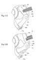
- the advancement lock bar 42 is rotated in the clockwise direction to effect the unlocking operation when hydraulic pressure of the hydraulic oil supplied through the double-lock bar path 31g (32d) acts on a side surface 42c' of the pressure receiving side arm portion 42c as shown in FIG. 11A and FIG. 11B .
- the advancement lock bar 42 is formed in such a manner that its center of gravity G1 is positioned near the supported portion 42a, i.e., it is placed on the inner side from the oscillation axis S2 in the radial direction running through the rotation axis S1 and in the range of a region biased by a predetermined distance toward a rotating direction for locking (the counterclockwise direction in FIG. 9A and FIG. 9B ) from a straight line L1 connecting the rotation axis S1 to the oscillation axis S2. That is, the center of gravity G1 is positioned so as to produce the centrifugal force in a direction to maintain the locked state in the entire oscillation range.
- T1 is rotating torque in the clockwise direction produced by hydraulic pressure of the hydraulic oil
- T2 is rotating torque in the counterclockwise direction produced by urging force of the advancement restriction spring 43
- T3 is rotating torque in the counterclockwise direction produced by the centrifugal force
- the center of gravity G1 of the advancement lock bar 42 is positioned in the vicinity of the supported portion 42a, i.e., in the vicinity of the fulcrum shaft 31i (the oscillation axis S2), a distance from the oscillation axis S2 (the center of the fulcrum shaft 31i) to the center of gravity G1 can be set small, and the rotating torque T3 produced by the centrifugal force can be decreased, whereby the influence of the centrifugal force on operations of the advancement lock bar 42 can be reduced as much as possible.
- the centrifugal force produced by the rotation of the housing rotor 30 acts to maintain the locked state of the advancement lock bar 42 and can prevent the locked state from being independently released and, on the other hand, allowing hydraulic pressure of the hydraulic oil supplied through the double-lock bar path 31g (32d) to act enables releasing the locked state provided by the advancement lock bar 42, and hence the lock mechanism can assuredly perform desired functions.
- the advancement restriction spring 43 is maintained in the compressed state with one end thereof being in contact with the receiving portion 31k of the housing member 31 and the other end thereof being in contact with a part of the engagement side arm portion 42b of the advancement lock bar 42, and it urges to rotate the advancement lock bar 42 in the counterclockwise direction so that the advancement lock bar 42 can be engaged with the lock cam 41 and locked.
- the urging force of the advancement restriction spring 43 is set so that the smooth releasing operation can be performed when hydraulic pressure of the hydraulic oil acts and the locked state of the advancement lock bar 42 is released.
- the retardation lock bar 44 is formed into a substantially L-like tabular shape, and includes a supported portion 44a into which the fulcrum shaft 31j that is provided in the housing member 31 and defines an oscillation axis S3 as an oscillation center is inserted in a bent region thereof, an engagement side arm portion 44b that extends in one direction from the supported portion 44a and can engage with the lock cam 41, and a pressure receiving side arm portion 44c that extends in the other direction from the supported portion 44a and receives pressure of the hydraulic oil.
- the retardation lock bar 44 is swingably supported within a vertical plane vertical to the rotation axis S1 by the fulcrum shaft 31j, urged to rotate toward the clockwise direction so as to come into contact with the stopper wall 31p with one end portion of the retardation restriction spring 45 being brought into contact with the engagement side arm portion 44b, and comes into contact with the lock cam 41 and restricts rotation of the lock cam 41 (i.e., the vane rotor 20) toward the retardation side from a pause position in a state that the retardation lock bar 44 is in contact with the stopper wall 31p and prevented from rotating in the clockwise direction.
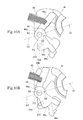
- the retardation lock bar 44 is rotated in the counterclockwise direction to effect the unlocking operation when hydraulic pressure of the hydraulic oil supplied through the double-lock bar path 31g (32d) acts on a side surface 44c' of the pressure receiving side arm portion 44c as shown in FIG. 12A . Since the retardation lock bar 44 rotates a predetermined angle and the retardation lock bar path 31h (the opening portion 31h') is opened as shown in FIG.
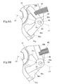
- the retardation lock bar 44 is formed in such a manner that its center of gravity G2 is positioned near the supported portion 44a, i.e., it is placed on the inner side from the oscillation axis S3 in the radial direction running through the rotation axis S1 and in the range of a region biased by a predetermined distance toward the rotating direction for locking (the clockwise direction in FIG. 10A and FIG. 10B ) from a straight line L2 connecting the rotation axis S1 to the oscillation axis S3. That is, the center of gravity G2 is positioned so as to produce the centrifugal force in a direction to maintain the locked state in the entire oscillation range.
- T1' is rotating torque in the counterclockwise direction produced by the hydraulic pressure of the hydraulic oil
- T2' is rotating torque in the clockwise direction produced by urging force of the retardation restriction spring 45
- T3' is rotating torque in the clockwise direction produced by the centrifugal force
- the center of gravity G2 of the retardation lock bar 44 is positioned in the vicinity of the supported portion 44a, i.e., in the vicinity of the fulcrum shaft 31j (the oscillation axis S3), a distance from the oscillation axis S3 (the center of the fulcrum shaft 31j) to the center of gravity G2 can be set small, and the rotating torque T3' produced by the centrifugal force can be decreased, whereby the influence of the centrifugal force on operations of the retardation lock bar 42 can be reduced as much as possible.
- the centrifugal force produced by the rotation of the housing rotor 30 acts to maintain the locked state of the retardation lock bar 44 and can prevent the locked state from being independently released and, on the other hand, allowing the hydraulic pressure of the hydraulic oil supplied through the double-lock bar path 31g (32d) and the hydraulic pressure of the hydraulic oil supplied through the retardation lock bar path 31h (the opening portion 31h') to act enables releasing the locked state of the retardation lock bar 44, and hence the lock mechanism can assuredly perform desired functions.
- the pressure receiving side arm portion 44b of the retardation lock bar 44 is formed so as to open/close the opening portion 31h' of the retardation lock bar path 31h by using the main surface that is opposed in the direction of the rotation axis S1, only the oscillating motion of the retardation lock bar 44 enables opening/closing the retardation lock bar path 31h (the retardation path), and hence the number of components can be reduced, thereby achieving simplification of the configuration and others.
- the retardation restriction spring 45 is maintained in the compressed state with one end thereof being in contact with the receiving portion 31k' of the housing member 31 and the other end thereof being in contact with a part of the engagement side arm portion 44b of the retardation lock bar 42, and it urges so as to rotate the retardation lock bar 42 in the clockwise direction so that the retardation lock bar 42 can be engaged with the lock cam 41 and locked.
- the urging force of the retardation restriction spring 45 is set so that the smooth releasing operation can be performed when the hydraulic pressure of the hydraulic oil acts and the locked state of the retardation lock bar 44 is released.
- the lock cam 41 and the vane rotor 20 are locked by each of the advancement lock bar 42 and the retardation lock bar 44 and positioned at a predetermined position (the intermediate position) in the state shown in each of FIG. 6 and FIG. 13 , positioned at the most advanced position when the locked state provided by each of the advancement lock bar 42 and the retardation lock bar 44 is released in the state shown in each of FIG. 7 and FIG. 14 and one vane portion 21 comes into contact with one baring portion 31d by the rotation in the clockwise direction, and positioned at the most retarded position when the locked state provided the retardation lock bar 44 alone is released in the state shown in each of FIG. 8 and FIG. 15 and one vane portion 21 comes into contact with one bearing portion 31d by rotation in the counterclockwise direction.
- the center bolt 50 has a solid cylindrical shape, and it includes a male screw portion 51 at an end side thereof. Further, when the center bolt 50 is inserted into the through hole 23 of the vane rotor 20 so as to define a predetermined annular gap and a male screw portion 51 thereof is screwed into a female screw portion 15 of the cam shaft 10, the lock cam 41 and the vane rotor 20 are integrally fastened with respect to the cam shaft 10.
- the assist mechanism 60 includes a bush member 61, an urging spring 62, and others arranged in the concave portion 31q of the housing member 31, and it is formed so as to exert auxiliary force for moving the lock cam 41 (the vane rotor 20 and the cam shaft 10) to the intermediate position from the most retarded position side.
- the hydraulic control system OCS is constituted of a hydraulic control valve 100 that is fitted and fixed with respect to a cylinder head CH or the like, a pump 70 that supplies the hydraulic oil to the hydraulic control valve 100, a supply path 71 through which the hydraulic oil discharged from the pump flows, a drain path 72 through which the hydraulic oil discharged from the hydraulic control valve 100 flows, an advancement path 73 which connects the hydraulic control valve 100 to the advancement path 13 and through which the hydraulic oil flows, a retardation path 74 which connects the hydraulic control valve 100 to the retardation path 14 and through which the hydraulic oil flows, controlling means (not shown) for controlling driving of the hydraulic control valve 100, and others.
- valve timing changing apparatus An operation of the valve timing changing apparatus will now be described with reference to FIG. 2 , FIG. 3 , FIG. 6 to FIG. 8 , and FIG. 13 to FIG. 15 .
- a drain mode that the hydraulic control valve 100 is driven and controlled so as to discharge the hydraulic oil in both the advancement chamber 30a and the retardation chamber 30b is selected over a predetermined time after turning off an ignition switch, the hydraulic oil in the advancement chamber 30a is discharged through the advancement path 73 and the drain path 72 in the mentioned order, and the hydraulic oil in the retardation chamber 30b is discharged through the retardation path 74 and the drain path 72 in the mentioned order.
- the lock cam 41 is positioned at the intermediate position as the predetermined position by the urging force of (the urging spring 62 of) the assist mechanism 60 and the urging force of the advancement restriction spring 43 and the retardation restriction spring 45 and locked by the advancement lock bar 42 and the retardation lock bar 44, and the vane rotor 20 is positioned at the intermediate position between the most advanced position and the most retarded position as shown in FIG. 13 .
- This intermediate position is set to valve timing that enables smooth startup when the startup of the engine begins (cranking). It is to be noted that, when the engine is stopped by engine stall contrary to the will of the driver, the controlling means determines this state, and the above-described drain mode is selected over the predetermined time like a situation where the ignition switch is turned off.
- the hydraulic control valve 100 is changed to a retardation mode in which the hydraulic oil in the advancement chamber 30a is discharged and the hydraulic oil can be supplied to the retardation chamber 30b, and it is maintained in this state.
- the hydraulic control valve 100 is driven over a predetermined period to enable the drain mode after the ignition switch is turned off to stop the engine or after the engine is stopped by the engine stall, a position of the vane rotor 20 with respect to the housing rotor 30 can be assuredly located at the previously set given intermediate position that is optimum for engine starting, and the subsequent engine starting can be smoothly carried out.
- the vane rotor 20 (the lock cam 41) has been already locked at the intermediate position, and the retardation mode is selected for the hydraulic control valve 100. It is to be noted that, when the vane rotor 20 (the lock cam 41) is displaced from the intermediate position and not locked, since the retardation lock bar 44 and the advancement lock bar 42 are constantly urged to rotate toward the locking position by the retardation restriction spring 45 and the advancement restriction spring 43, respectively, and fluctuation torque is generated by cranking, they are automatically moved to the intermediate position and locked.
- the hydraulic oil in the advancement chamber 30a is discharged through the advancement path 73 and the drain path 72 in the mentioned order and, in this state, the hydraulic oil is supplied to the retardation chamber 30b via the pump 70, the supply path 71, and the retardation path 74 in the mentioned order.
- the hydraulic control valve 100 is appropriately switched, and the phase control is carried out in such a manner that the vane rotor 20 (the cam shaft 10) is changed from the intermediate position to the advancement side (an advancement mode) or the retardation side (a retardation mode) and held at a predetermined angular position (a holding mode).
- the hydraulic control valve 100 is switched, and the advancement mode in which the hydraulic oil in the retardation chamber 30b is discharged and the hydraulic oil is supplied to the advancement chamber 30a is selected.
- the hydraulic oil is supplied to the advancement chamber 30a via the pump 70, the supply path 71, and the advancement path 73 in the mentioned order, the hydraulic pressure of the hydraulic oil is supplied to the advancement lock bar 42 and the retardation lock bar 44 through the double-lock bar paths 31g and 32d to effect unlocking as shown in FIG. 7 , the retardation lock bar path 31h is opened when the retardation lock bar 44 is rotated a predetermined angle, and the hydraulic pressure maintains the retardation lock bar 44 in the unlocked state.
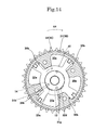
- the hydraulic oil is discharged from the retardation chamber 30b through the retardation path 74 and the drain path 72 in the mentioned order. As a result, the vane rotor 20 can be moved to the advancement side, and the phase can be thereby changed as shown in FIG. 14 .
- the hydraulic control valve 100 is switched, and the holding mode (a pump mode) that the hydraulic oil is supplied to the advancement chamber 30a and the retardation chamber 30b is selected.
- the hydraulic oil is supplied to the advancement chamber 30a through the pump 70, the supply path 71, and the advancement path 73 in this order, the hydraulic oil is supplied to the retardation chamber 30b via the pump 70, the supply path 71, and the retardation path 74, the hydraulic pressure of the hydraulic oil is supplied to the advancement lock bar 42 and the retardation lock bar 44 via the double-lock bar paths 31g and 32d to effect unlocking, the retardation lock bar path 31his opened when the retardation lock bar 44 is rotated a predetermined angle, and the hydraulic pressure maintains the retardation lock bar 44 in the unlocked state. That is, the hydraulic pressure acting on the advancement chamber 30a and the retardation chamber 30b enables holding the vane rotor 20 in a predetermined intermediate phase.
- the hydraulic control valve 100 is temporarily switched from the intermediate position at the start-up to the advancement mode or the holding mode (the pump mode), then the retardation mode that the hydraulic oil is supplied to the retardation chamber 30b and the hydraulic oil in the advancement chamber 30a is discharged is selected.
- the locked state provided by the retardation lock bar 44 is released and the unlocked state is maintained as shown in FIG. 8 by the hydraulic pressure that has acted in the temporarily switched advancement mode or the holding mode (the pump mode), the hydraulic oil in the advancement chamber 30a is discharged through the advancement path 73 and the drain path 72 in the mentioned order, and the hydraulic oil is supplied to the retardation chamber 30b through the pump 70, the supply path 71, and the retardation path 74 in this order.
- the vane rotor 20 can be moved to the retardation side and the phase can be changed as shown in FIG. 15 .
- the phase of the vane rotor 20 with respect to the housing rotor 30 can be held at the intermediate position until complete explosion occurs at the time of the engine starting, and hence stable starting performance of the engine can be assured.
- the retardation mode is selected in a situation where the locked state provided by the lock mechanism 40 is maintained at the time of the engine starting, supplying the hydraulic oil by cranking at the time of the engine starting enables avoiding abnormal abrasion, component damage, and others in the slide portion in the housing rotor 30, the vane rotor 20, or the like, the lock mechanism 40, and any other mechanism, and the vane rotor 20 can be urged to rotate toward the retardation side, and hence occurrence of fluttering, a tap noise, and others can be prevented.
- the centrifugal force produced by the rotation acts so as to maintain the locked state, the centrifugal force can prevent the locked state from being independently released and, on the other hand, the locked state provided by the lock bar can be released by allowing the hydraulic pressure of the hydraulic oil to act, whereby the lock mechanism can assuredly effect desired functions.
- the housing rotor 30 including the sprocket 32a that transmits rotating force of the crank shaft has been described, the present invention is not restricted thereto and, if means for transmitting rotating drive force of the crank shaft has any other configuration (e.g., a toothed timing belt), a housing rotor including a component (e.g., a toothed pulley) suitable for this configuration can be adopted.
- a housing rotor including a component e.g., a toothed pulley
- the present invention is not restricted thereto, and it is possible to adopt any other lock mechanism as long as it includes a lock bar that can oscillate within a vertical plane vertical to the rotation axis S1 and effect locking at a predetermined position (the intermediate position).
- the present invention is not restricted thereto, and a closed mode that a flow of the hydraulic oil to the advancement chamber 30a and the retardation chamber 30b is interrupted may be adopted.
Landscapes
- Engineering & Computer Science (AREA)
- Mechanical Engineering (AREA)
- General Engineering & Computer Science (AREA)
- Valve Device For Special Equipments (AREA)
Abstract
Description
- The present invention relates to a valve timing changing apparatus that changes opening/closing timing (valve timing)of an inlet valve or an exhaust valve of an internal combustion engine in accordance with an operating condition.
- As a conventional valve timing changing apparatus, there is known one that includes: a housing rotor (a housing) that rotates in synchronization with a crank shaft; a vane rotor that rotates in synchronization with a cam shaft, is accommodated in the housing rotor to divide an accommodation chamber into two chambers, i.e., a retardation chamber and an advancement chamber, and can relatively rotate a predetermined operation angle (an angular range between the most advanced position and the most retarded position) with respect to the housing rotor; a lock mechanism (e.g., a lock pin and a spring) that locks the vane rotor with respect to the housing rotor at an intermediate position between the most retarded position and the most advanced position when an engine is stopped or started and unlocks the vane rotor by using hydraulic pressure; a hydraulic control valve that controls supply and discharge of a hydraulic oil with respect to the advancement chamber and the retardation chamber or a hydraulic control valve that controls supply and discharge of the hydraulic oil with respect to the lock mechanism; and others, thereby appropriately driving and controlling the hydraulic control valve and effecting locking at the intermediate position at a time of start of the engine to assure starting performance (see, e.g., Japanese Unexamined Patent Application Publication No.
2009-257261 - In this apparatus, since the lock pin of the lock mechanism reciprocates in a direction parallel to a rotary shaft of the cam shaft, centrifugal force that affects the locking operation and the unlocking operation does not act on the lock pin, but a size of a vane portion must be increased since the lock mechanism (the lock pin) is accommodated in the vane portion of the vane rotor, and hence there arises a problem that an operating angle can be set in a limited range alone.
- Further, as another valve timing changing apparatus, like the above example, there is known one that includes: a housing rotor (a housing member); a vane rotor (a rotor member); a lock mechanism that locks the vane rotor with respect to the housing rotor; a hydraulic circuit that supplies and discharges a hydraulic oil with respect to the lock mechanism; and others, adopts as the lock mechanism: a lock member that is arranged in the housing rotor, protrudes within a plane vertical to a rotary axis of the cam shaft along the radial direction, and can fit to a receiving portion of the vane rotor; and a spring that urges the lock member in a locking direction, and also adopts in order to generate counter force in a direction to oppose centrifugal force produced in the lock member of the lock mechanism and cancel the centrifugal force: a counter member that is accommodated in the housing rotor and can move in the radial direction; and a shaft member that is accommodated in the housing rotor, supported to allow its oscillating motion, and has one end that comes into contact with the lock member and the other end that comes into contact with the counter member (see, e.g., Japanese Patent No.
4062224 - In this apparatus, although the centrifugal force produced in the lock member can be canceled, since a dedicated cancel mechanism is required, the configuration is complicated, and a space where the cancel mechanism is arranged is required, there arises a problem that a size of the apparatus is increased.
- In view of the above-described problems, it is an object of the present invention to provide a valve timing changing apparatus that can achieve simplification of a configuration, miniaturization of the apparatus, a reduction in cost, and others, set an operating angle between the most retarded position and the most advanced position larger than that in the conventional technology, avoid an influence of centrifugal force in a lock mechanism to assure locking and unlocking operations performed by the lock mechanism, prevent fluttering of the vane rotor, a tap noise or abrasion of the lock mechanism, and others, and assure stable starting performance of the engine.
- A valve timing changing apparatus according to the present invention that achieves the object includes: a housing rotor that rotates on a rotation axis of a cam shaft in interlock with rotation of a crank shaft; a vane rotor that is accommodated in an accommodation chamber of the housing rotor so as to be relatively rotatable in a predetermined angular range, divides the accommodation chamber into two, i.e., an advancement chamber and a retardation chamber, and integrally rotates with the cam shaft; an advancement path which communicates with the advancement chamber and through which an hydraulic oil passes; a retardation path which communicates with the retardation chamber and through which the hydraulic oil passes; and a lock mechanism which locks the vane rotor at a predetermined position in the predetermined angular range with respect to the housing rotor and unlocks the vane rotor by hydraulic pressure of the hydraulic oil, the valve timing changing apparatus changing opening/closing timing of an inlet valve or an exhaust valve that is driven to be opened/closed by the cam shaft, wherein the lock mechanism includes: a lock bar that is supported by the housing rotor so as to oscillate about a predetermined oscillation center within a vertical plane vertical to the rotation axis; and an urging spring that urges the lock bar toward a locked position of the vane rotor, and a center of gravity of the lock bar is positioned so as to generate centrifugal force in a direction to maintain the locked state in the entire oscillation range.
- According to this configuration, since the lock mechanism that locks the vane rotor (the cam shaft) with respect to the housing rotor at the predetermined position in the predetermined angular range includes the lock bar that oscillates within the vertical plane vertical to the rotation axis of the cam shaft and the urging spring thereof, in case that the thick vane that has the lock pin accommodated therein like the conventional example is held at the intermediate position in the accommodation chamber at the time of start, a control angle for phase adjustment from the position at the time of start toward the advancement direction cannot be assured, but the vane of the present invention does not require excess thickness, a large phase adjustment angle between the most advanced position and the most retarded position can be set, and hence extensive phase control can be carried out as required.
- In particular, since the center of gravity of the lock bar is positioned so as to generate the centrifugal force in the direction to maintain the locked state in the entire oscillation range, the centrifugal force generated by the rotation acts so as to maintain the locked state and, on the other hand, the locked state provided by the lock bar is released by allowing the hydraulic pressure of the hydraulic oil to act, and thus the lock mechanism can assuredly perform predetermined functions.
- In the above-described configuration, it is possible to adopt the configuration where the lock bar is formed in such a manner that its center of gravity is placed in a range of a region that is on the inner side from the oscillation center in the radial direction running through the rotation axis and is biased by a predetermined distance toward a rotational direction for locking from a straight line connecting the rotation axis line and the oscillation center.
- According to this configuration, since the center of gravity of the lock bar is positioned in the above-described range, rotary torque produced by the centrifugal force does not act on the lock bar, or torque that causes rotation in the locking direction acts even if the rotary torque acts on the lock bar, and hence the lock bar can be assuredly maintained at its locked position.
- In the above-described configuration, it is possible to adopt a structure where the housing rotor includes: a housing member having an isolation wall that defines an isolation chamber which is isolated from the accommodation chamber and in which the lock mechanism is arranged; and a cover member that is detachably formed with respect to the housing member so as to define the isolation chamber in cooperation with the isolation wall, the lock mechanism includes a lock cam that is coupled to integrally rotate with the vane rotor via a through hole provided in the isolation wall, and the lock bar is formed to engage with the lock cam to lock the vane rotor and disengage from the lock cam to unlock the vane rotor.
- According to this configuration, since the isolation chamber in which the lock mechanism is arranged is defined by the isolation wall of the housing member and the cover member that is attachable to/detachable from the housing member, the lock mechanism assembling operation or removing operation can be readily carried out with the vane rotor incorporated in the accommodation chamber of the housing member, the vane rotor can be locked with respect to the housing rotor at the predetermined position (the intermediate position) when the lock bar locks the lock cam at a time of engine starting (at a time of cranking) , and the locked state provided by the lock bar can be released by using the hydraulic oil pressure after the engine starting.
- That is, since the vane rotor is assuredly maintained at the predetermined position (the intermediate position) by using the lock mechanism, the engine can be more securely started, and since the lock mechanism does not directly lock the vane rotor, the vane portion of the vane rotor can be thinned, thereby increasing a freedom degree of design and a freedom degree of layout.
- In the above-descried configuration, it is possible to adopt a configuration where the lock bar is formed into a substantially L-like tabular shape and has: a supported portion into which a fulcrum shaft provided to the housing rotor is inserted in a bent region thereof; an engagement side arm portion which extends from the supported portion in one direction and is engageable with the lock cam; and a pressure receiving side arm portion which extends from the supported portion in the other direction and receives pressure of the hydraulic oil, and the center of gravity of the lock bar is positioned near the supported portion.
- According to this configuration, the supported portion of the lock bar is supported by the fulcrum shaft so as to allow its oscillating motion, the engagement side arm portion of the lock bar engages with the lock cam to lock the vane rotor and, on the other hand, the hydraulic pressure of the hydraulic oil acts on the pressure receiving side arm portion so that the engagement side arm portion disengages from the lock cam, whereby the vane rotor is unlocked.
- Here, since the center of gravity of the lock bar is positioned in the vicinity of the supported portion, i.e., in the vicinity of the fulcrum shaft, a distance from the oscillation center (the center of the fulcrum shaft) to the center of gravity can be set small, the rotary torque can be reduced by using the centrifugal force, and hence an influence of the centrifugal force on the operation of the lock bar can be decreased as much as possible.
- In the above-described configuration, it is possible to adopt a configuration where the lock bar includes: an advancement lock bar that restricts rotation of the vane rotor toward the advancement side; and a retardation lock bar that restricts rotation of the vane rotor toward the retardation side, and the urging spring includes: an advancement restriction spring that urges the advancement lock bar so as to be locked in engagement with the lock cam; and a retardation restriction spring that urges the retardation lock bar so as to be locked in engagement with the lock cam.
- According to this configuration, since the advancement lock bar is urged by the advancement restriction spring and the displacement of the lock cam (i.e., the vane rotor) from a predetermined position (the intermediate position) toward the advancement side and the retardation lock bar is urged by the retardation restriction spring and restricts the displacement of the lock cam (i.e., the vane rotor) from the predetermined position (i.e., the intermediate position) toward the retardation side in the condition that the hydraulic pressure of the hydraulic oil does not act, the vane rotor can be assuredly positioned at the predetermined position (the intermediate position), fluctuating torque at the time of cranking and urging force of the advancement restriction spring and the retardation restriction spring enable the vane rotor to return to the predetermined position (the intermediate position) even if the vane rotor is displaced from the predetermined position (the intermediate position) at a time of engine stop.
- In the above-described configuration, it is possible to adopt a configuration where the advancement path is formed so as to lead the hydraulic pressure of the hydraulic oil so that each of the advancement lock bar and the retardation lock bar is unlocked, and the retardation path is formed so as to lead the hydraulic pressure of the hydraulic oil so that the retardation lock bar alone is maintained in the unlocked state after unlocking is carried out by using the hydraulic pressure of the hydraulic oil led through the advancement path.
- According to this configuration, since the retardation lock bar is not unlocked unless the hydraulic pressure of the hydraulic oil is not led through the advancement path even if the hydraulic pressure of the hydraulic oil is led through the retardation path, a phase of the vane rotor with respect to the housing rotor can be held at the predetermined position (the intermediate position) until this apparatus becomes controllable at the time of engine starting, and hence stable starting performance of the engine can be assured.
- In the above-described configuration, it is possible to adopt a configuration where the retardation path defines an opening portion that is opened in a direction of the rotation axis, and the pressure receiving side arm portion of the retardation lock bar is formed so as to open/close the opening portion of the retardation path by a main surface of the retardation lock bar that is opposed to the opening portion in the direction of the rotation axis.
- According to this configuration, since the retardation path can be opened or closed by the oscillating operation of the lock bar only, the number of components can be reduced, and simplification of the configuration and others can be achieved.
- According to the above-described valve timing changing apparatus, simplification of the structure, miniaturization of the apparatus, a reduction in cost, and others can be achieved, the operating angle between the most retarded position and the most advanced position can be set larger than that in the conventional apparatus, an influence of the centrifugal force in the lock mechanism can be avoided, the locking and unlocking operations of the lock mechanism can be assured, fluttering of the vane rotor, a tap noise or abrasion in the lock mechanism, and others can be avoided, and stable starting performance of the engine can be assured.
-
-
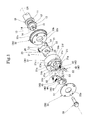
FIG. 1 is an exploded perspective view showing a valve timing changing apparatus according to the present invention; -
FIG. 2 is a cross-sectional view showing the valve timing changing apparatus according to the present invention; -
FIG. 3 is a cross-sectional view showing the valve timing changing apparatus according to the present invention; -
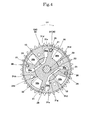
FIG. 4 is a cross-sectional view showing an advancement path (an advancement chamber path) communicating with an advancement chamber in a state that a vane rotor forming a part of the valve timing changing apparatus is located at a predetermined position (an intermediate position); -
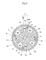
FIG. 5 is a cross-sectional view showing a retardation path (a retardation chamber room) communicating with a retardation chamber in a state that the vane rotor forming a part of the valve timing changing apparatus is located at the predetermined position (the intermediate position); -
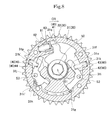
FIG. 6 is a cross-sectional view showing a state that a lock mechanism (a lock cam, a lock lever) forming a part of the valve timing changing apparatus locks the vane rotor at the predetermined position (the intermediate position); -
FIG. 7 is a cross-sectional view showing a state that the lock mechanism (the lock cam, the lock lever) forming a part of the valve timing changing apparatus is released and the vane rotor is moved to the advancement side; -
FIG. 8 is a cross-sectional view showing a state that the lock mechanism (the lock cam, the lock lever) forming a part of the valve timing changing apparatus is released and the vane rotor is moved to the retardation side; -
FIG. 9A is a partial view showing a locked state in a part (an advancement lock bar and an advancement restriction spring) of the lock mechanism, andFIG. 9B is a partial view showing an unlocked state in a part of the lock mechanism; -
FIG. 10A is a partial view showing a locked state in a part (a retardation lock bar and a retardation restriction spring) of the lock mechanism, andFIG. 10B is a partial view showing an unlocked state in a part of the lock mechanism; -
FIG. 11A is a partial view showing a state of a hydraulic oil at a locking position in a part (the advancement lock bar and the advancement restriction spring) of the lock mechanism, andFIG. 11B is a partial view showing a state of the hydraulic oil at an unlocking position in a part of the lock mechanism; -
FIG. 12A is a partial view showing a state of the hydraulic oil at the locking position in a part (the retardation lock bar and the retardation restriction spring) of the lock mechanism, andFIG. 12B is a partial view showing a state of the hydraulic oil at the unlocking position in a part of the lock mechanism; -
FIG. 13 is a cross-sectional view showing a state that the vane rotor forming a part of the valve timing changing apparatus is located at the predetermined position (the intermediate position); -
FIG. 14 is a cross-sectional view showing a state that the vane rotor forming a part of the valve timing changing apparatus is located at the most advanced position; and -
FIG. 15 is a cross-sectional view showing a state that the vane rotor forming a part of the valve timing changing apparatus is located at the most retarded position. - An embodiment according to the present invention will now be described hereinafter with reference to the accompanying drawings.
- As shown in
FIG. 1 to FIG. 3 , this valve timing changing apparatus includes: avane rotor 20 that can be detachably fixed to acam shaft 10; ahousing rotor 30 that rotates on a rotation axis S1 of thecam shaft 10, relatively rotatably accommodates thevane rotor 20, and defines anadvancement chamber 30a and aretardation chamber 30b in cooperation with thevane rotor 20; a lock mechanism 40 (alock cam 41, anadvancement lock cover 42, anadvancement restriction spring 43, aretardation lock bar 44, and a retardation restriction spring 45) that is arranged in an isolation chamber of thehousing rotor 30 so as to lock thevane rotor 20 with respect to thehousing rotor 30 at a predetermined position (an intermediate position); acenter bolt 50 that fastens thevane rotor 20 with respect to thecam shaft 10; anassist mechanism 60 that assists thelock cam 41 included in thelock mechanism 40 to return to the predetermined position (the intermediate position), a hydraulic control system OCS that controls a flow of a hydraulic oil (a lubricant); and others. - It is to be noted that the
cam shaft 10 drives an inlet valve or an exhaust valve of an engine to be opened or closed by using a cam function, and thehousing rotor 30 interlocks with rotation of a crank shaft via a chain or the like and transmits rotary drive force of the crank shaft to thecam shaft 10 through thevane rotor 20. - As shown in
FIG. 1 to FIG. 3 , thecam shaft 10 is supported to be rotatable (to rotate in a direction of an arrow CR inFIG. 1 ) on a rotation axis S1 by a bearing B (seeFIG. 2 ) formed on a cylinder head (not shown) of the engine. Thecam shaft 10 includes ajournal portion 11 supported by the bearing B, acylindrical portion 12 that supports thehousing rotor 30 so as to allow its oscillating motion, anadvancement path 13 through which the hydraulic oil is supplied to or discharged from theadvancement chamber 30a and theretardation lock bar 42, aretardation path 14 through which the hydraulic oil is supplied to or discharged from theretardation chamber 30b and theretardation lock bar 44, afemale screw portion 15 that fastens thecenter bolt 50, and others. - As shown in
FIG. 1 to FIG. 5 , thevane rotor 20 includes fourvane portions 21, ahub portion 22 that integrally holds the fourvane portions 21 at equal intervals, a throughhole 23 that is formed in thehub portion 22 and into which thecenter bolt 50 is inserted, anadvancement chamber path 24 formed to branch from theadvancement path 13 for supply and discharge of the hydraulic oil with respect to theadvancement chamber 30a, aretardation chamber path 25 formed to branch from theretardation path 14 for supply and discharge of the hydraulic oil with respect to theretardation chamber 30b, aseal member 26 fitted in a groove portion formed in an end of eachvane portion 21, and others. Thevane rotor 20 is fastened together with thelock cam 41 with respect to thecam shaft 10 by use of thecenter bolt 50 and integrally rotates with thecam shaft 10. - The
housing rotor 30 is supported to be rotatable on the rotation axis S1 of thecam shaft 10 in interlock with rotation of the crank shaft, constituted of ahousing member 31, asprocket member 32 that is coupled with a rear surface side of thehousing member 31, and acover member 33 coupled with a front surface side of thehousing member 31, and formed in such a manner that it accommodates the vane rotor 20 (defines the accommodation chamber) so as to be relatively rotatable in a predetermined angular range (an angular range between the most advancement position and the most retardation position), that it accommodates the lock mechanism 40 (defines the isolation chamber) and that it is divided into two parts, i.e., theadvancement chamber 30a and theretardation chamber 30b by (thevane portions 21 of) the accommodatedvane rotor 20. - As shown in
FIG. 1 to FIG. 5 andFIG. 13 , thehousing member 31 includes acylindrical wall 31a, anisolation wall 31b, athrough hole 31c provided at the center of theisolation wall 31b, four bearingportions 31d protruding toward the center on the rear surface side of theisolation wall 31b,concave portions 31e each of which is defined between therespective bearing portions 31d and at the central portion and accommodates thevane rotor 20, aconcave portion 31f that is formed on the front surface side of theisolation wall 31b and accommodates the lock mechanism, a double-lock bar path 31g that is formed to be branched from theadvancement path 13 for supply and discharge of the hydraulic oil with respect to anadvancement lock bar 42 and aretardation lock bar 44, a retardationlock bar path 31h formed to be branched from theretardation path 14 for supply and discharge of the hydraulic oil with respect to theretardation lock bar 44, anopening portion 31h',fulcrum shafts portions stopper walls 31o and 31p, aconcave portion 31q that accommodates theassist mechanism 60, and others. - As shown in
FIG. 6 to FIG. 8 , the double-lock bar path 31g is opened in theconcave portion 31f, and it is formed in such a manner that the hydraulic pressure is led to the side surfaces of (pressure receiving side arm portions of) theadvancement lock bar 42 and theretardation lock bar 44 and the hydraulic pressure acts in a direction to release the locked state of each lock bar. - As shown in
FIG. 6 to FIG. 8 , the retardationlock bar path 31h is opened in theconcave portion 31f, and it is formed in such a manner that the hydraulic pressure is led to a main surface (a plane facing in a direction of the rotation axis S1) of theretardation lock bar 44, a closed state provided by the main surface of theretardation lock bar 44 is released to lead the hydraulic pressure to the side surface of (the pressure receiving side arm portion of) theretardation lock bar 44 and the hydraulic pressure acts in the direction to release the locked state (i.e., that thepath 31h is connected to anopening portion 31h' having a concave long groove shape formed by grinding down the surface of theconcave portion 31f) when theretardation lock bar 44 is rotated (moved) in a direction to release the locked state at a predetermined angle by the hydraulic pressure led from the double-lock bar path 31g. - As shown in
FIG. 1 to FIG. 3 , thesprocket member 32 includes asprocket 32a around which a chain that transmits rotary drive force of the crank shaft is wound, an innerperipheral surface 32b rotatably fitted on thecylindrical portion 12 of thecam shaft 10, afront surface 32c with which the rear surface of thevane rotor 20 slidably comes into contact, a double-lock bar path 32d formed to be branched from theadvancement path 13 for supply and discharge of the hydraulic oil with respect to theadvancement lock bar 42 and theretardation lock bar 44, a retardationlock bar path 32e formed to be branched from theretardation path 14 for supply and discharge of the hydraulic oil with respect to theretardation lock bar 44. - As shown in
FIG. 13 to FIG. 15 , the both-lock bar path 32d is defined by an arc-like path extending in the circumferential direction and a path extending in the radial direction, and it is formed to enable theadvancement path 13 and the double-lock bar path 31g to communicate with each other during a period that thevane rotor 20 relatively rotates between the most advanced position and the most retarded position. - As shown in
FIG. 13 to FIG. 15 , the retardationlock bar path 32e is defined by an arc-like path extending in the circumferential direction and a path extending in the radial direction, and it is formed to enable theretardation path 14 and the retardationlock bar path 31h to communicate with each other during a period that thevane rotor 20 relatively rotates between the most advanced position and the most retarded position. - As described above, since the
advancement path 13 is formed to branch into the double-lock bar paths advancement chamber path 24 and theretardation path 14 is formed to branch into the retardationlock bar paths retardation chamber path 25, responsiveness at a time of unlocking is good. Further since thelock mechanism 40 can be smoothly operated without being affected by the hydraulic oil in theadvancement chamber 30a and theretardation chamber 30b. Further, both thelock bar paths lock bar paths housing member 31 and thesprocket 32, respectively, the double-lock bar paths lock bar paths cam shaft 10, thesprocket member 32, and thehousing member 31. - As shown in
FIG. 1 to FIG. 3 , thecover member 33 has acircular hole 33a into which thecenter bolt 50 is inserted and others, and it is formed so as to be attachable to/detachable from thehousing member 31. - Further, the
housing member 31, thesprocket member 32, and thecover member 33 are fastened by using a bolt and others, and the isolation chamber in which thelock mechanism 40 is arranged is defined when thecover member 33 is coupled with thehousing member 31. - As shown in
FIG. 1 andFIG. 6 toFIG. 8 , thelock mechanism 40 is constituted of thelock cam 41, theadvancement lock bar 42, theadvancement restriction spring 43, theretardation lock bar 44, and theretardation restriction spring 45, and it is formed in such a manner that thevane rotor 20 is locked at a predetermined position (the intermediate position) in a predetermined angular range (between the most advanced position and the most retarded position) where thevane rotor 20 can relatively rotate with respect to thehousing rotor 30. - The
lock cam 41 is fastened together with thevane rotor 20 with respect to thecam shaft 10 by thecenter bolt 50, rotates in the predetermined angular range, and formed so that theadvancement lock bar 42 and theretardation lock bar 44 can be separably engaged. - As shown in
FIG. 9A and FIG. 9B , theadvancement lock bar 42 is formed into a substantially L-like tabular shape, and includes a supportedportion 42a into which afulcrum shaft 31i that is provided in thehousing member 31 and defines an oscillation axis S2 as an oscillation center is inserted in a bent region thereof, an engagementside arm portion 42b that extends in one direction from the supportedportion 42a and can engage with thelock cam 41, and a pressure receivingside arm portion 42c that extends in the other direction from the supportedportion 42a and receives pressure of the hydraulic oil. - Furthermore, the
advancement lock bar 42 is swingably supported within a vertical plane vertical to the rotation axis S1 by thefulcrum shaft 31i, urged to rotate toward the counterclockwise direction so as to come into contact with the stopper wall 31o with one end portion of theadvancement regulation spring 43 being brought into contact with the engagementside arm portion 42b, and comes into contact with thelock cam 41 and restricts rotation of the lock cam 41 (i.e., the vane rotor 20) toward the advancement side from a pause position in a state that theadvancement lock bar 42 is in contact with the stopper wall 31o and prevented from rotating in the counterclockwise direction. On the other hand, theadvancement lock bar 42 is rotated in the clockwise direction to effect the unlocking operation when hydraulic pressure of the hydraulic oil supplied through the double-lock bar path 31g (32d) acts on aside surface 42c' of the pressure receivingside arm portion 42c as shown inFIG. 11A and FIG. 11B . - Here, as shown in
FIG. 9A and FIG. 9B , theadvancement lock bar 42 is formed in such a manner that its center of gravity G1 is positioned near the supportedportion 42a, i.e., it is placed on the inner side from the oscillation axis S2 in the radial direction running through the rotation axis S1 and in the range of a region biased by a predetermined distance toward a rotating direction for locking (the counterclockwise direction inFIG. 9A and FIG. 9B ) from a straight line L1 connecting the rotation axis S1 to the oscillation axis S2. That is, the center of gravity G1 is positioned so as to produce the centrifugal force in a direction to maintain the locked state in the entire oscillation range. - Here, assuming that T1 is rotating torque in the clockwise direction produced by hydraulic pressure of the hydraulic oil, T2 is rotating torque in the counterclockwise direction produced by urging force of the
advancement restriction spring 43, and T3 is rotating torque in the counterclockwise direction produced by the centrifugal force, T1>T2+T3 is set. - In particular, since the center of gravity G1 of the
advancement lock bar 42 is positioned in the vicinity of the supportedportion 42a, i.e., in the vicinity of thefulcrum shaft 31i (the oscillation axis S2), a distance from the oscillation axis S2 (the center of thefulcrum shaft 31i) to the center of gravity G1 can be set small, and the rotating torque T3 produced by the centrifugal force can be decreased, whereby the influence of the centrifugal force on operations of theadvancement lock bar 42 can be reduced as much as possible. - Therefore, the centrifugal force produced by the rotation of the
housing rotor 30 acts to maintain the locked state of theadvancement lock bar 42 and can prevent the locked state from being independently released and, on the other hand, allowing hydraulic pressure of the hydraulic oil supplied through the double-lock bar path 31g (32d) to act enables releasing the locked state provided by theadvancement lock bar 42, and hence the lock mechanism can assuredly perform desired functions. - As shown in
FIG. 6 to FIG. 8 , theadvancement restriction spring 43 is maintained in the compressed state with one end thereof being in contact with the receivingportion 31k of thehousing member 31 and the other end thereof being in contact with a part of the engagementside arm portion 42b of theadvancement lock bar 42, and it urges to rotate theadvancement lock bar 42 in the counterclockwise direction so that theadvancement lock bar 42 can be engaged with thelock cam 41 and locked. - Here, the urging force of the
advancement restriction spring 43 is set so that the smooth releasing operation can be performed when hydraulic pressure of the hydraulic oil acts and the locked state of theadvancement lock bar 42 is released. - As shown in
FIG. 10A and FIG. 10B , theretardation lock bar 44 is formed into a substantially L-like tabular shape, and includes a supportedportion 44a into which thefulcrum shaft 31j that is provided in thehousing member 31 and defines an oscillation axis S3 as an oscillation center is inserted in a bent region thereof, an engagementside arm portion 44b that extends in one direction from the supportedportion 44a and can engage with thelock cam 41, and a pressure receivingside arm portion 44c that extends in the other direction from the supportedportion 44a and receives pressure of the hydraulic oil. - Moreover, the
retardation lock bar 44 is swingably supported within a vertical plane vertical to the rotation axis S1 by thefulcrum shaft 31j, urged to rotate toward the clockwise direction so as to come into contact with thestopper wall 31p with one end portion of theretardation restriction spring 45 being brought into contact with the engagementside arm portion 44b, and comes into contact with thelock cam 41 and restricts rotation of the lock cam 41 (i.e., the vane rotor 20) toward the retardation side from a pause position in a state that theretardation lock bar 44 is in contact with thestopper wall 31p and prevented from rotating in the clockwise direction. On the other hand, theretardation lock bar 44 is rotated in the counterclockwise direction to effect the unlocking operation when hydraulic pressure of the hydraulic oil supplied through the double-lock bar path 31g (32d) acts on aside surface 44c' of the pressure receivingside arm portion 44c as shown inFIG. 12A . Since theretardation lock bar 44 rotates a predetermined angle and the retardationlock bar path 31h (theopening portion 31h') is opened as shown inFIG. 10B , even if the hydraulic pressure of the hydraulic oil supplied from the double-lock bar path 31g (32d) does not act, as shown inFIG.8 andFIG.12B , the hydraulic pressure of the hydraulic oil supplied through the retardationlock bar path 31h (theopening portion 31h') alone acts on theside surface 44c' of the pressure receivingside arm portion 44c to enable maintaining the unlocked state. - Here, as shown in
FIG. 10A and FIG. 10B , theretardation lock bar 44 is formed in such a manner that its center of gravity G2 is positioned near the supportedportion 44a, i.e., it is placed on the inner side from the oscillation axis S3 in the radial direction running through the rotation axis S1 and in the range of a region biased by a predetermined distance toward the rotating direction for locking (the clockwise direction inFIG. 10A and FIG. 10B ) from a straight line L2 connecting the rotation axis S1 to the oscillation axis S3. That is, the center of gravity G2 is positioned so as to produce the centrifugal force in a direction to maintain the locked state in the entire oscillation range. - Here, assuming that T1' is rotating torque in the counterclockwise direction produced by the hydraulic pressure of the hydraulic oil, T2' is rotating torque in the clockwise direction produced by urging force of the
retardation restriction spring 45, and T3' is rotating torque in the clockwise direction produced by the centrifugal force, T1'>T2'+T3' is set. - In particular, since the center of gravity G2 of the
retardation lock bar 44 is positioned in the vicinity of the supportedportion 44a, i.e., in the vicinity of thefulcrum shaft 31j (the oscillation axis S3), a distance from the oscillation axis S3 (the center of thefulcrum shaft 31j) to the center of gravity G2 can be set small, and the rotating torque T3' produced by the centrifugal force can be decreased, whereby the influence of the centrifugal force on operations of theretardation lock bar 42 can be reduced as much as possible. - Therefore, the centrifugal force produced by the rotation of the
housing rotor 30 acts to maintain the locked state of theretardation lock bar 44 and can prevent the locked state from being independently released and, on the other hand, allowing the hydraulic pressure of the hydraulic oil supplied through the double-lock bar path 31g (32d) and the hydraulic pressure of the hydraulic oil supplied through the retardationlock bar path 31h (theopening portion 31h') to act enables releasing the locked state of theretardation lock bar 44, and hence the lock mechanism can assuredly perform desired functions. - Further, since the pressure receiving
side arm portion 44b of theretardation lock bar 44 is formed so as to open/close theopening portion 31h' of the retardationlock bar path 31h by using the main surface that is opposed in the direction of the rotation axis S1, only the oscillating motion of theretardation lock bar 44 enables opening/closing the retardationlock bar path 31h (the retardation path), and hence the number of components can be reduced, thereby achieving simplification of the configuration and others. - Additionally, as shown in
FIG. 6 to FIG. 8 , theretardation restriction spring 45 is maintained in the compressed state with one end thereof being in contact with the receivingportion 31k' of thehousing member 31 and the other end thereof being in contact with a part of the engagementside arm portion 44b of theretardation lock bar 42, and it urges so as to rotate theretardation lock bar 42 in the clockwise direction so that theretardation lock bar 42 can be engaged with thelock cam 41 and locked. - Here, the urging force of the
retardation restriction spring 45 is set so that the smooth releasing operation can be performed when the hydraulic pressure of the hydraulic oil acts and the locked state of theretardation lock bar 44 is released. - According to the
lock mechanism 40 having the above-described configuration, thelock cam 41 and thevane rotor 20 are locked by each of theadvancement lock bar 42 and theretardation lock bar 44 and positioned at a predetermined position (the intermediate position) in the state shown in each ofFIG. 6 andFIG. 13 , positioned at the most advanced position when the locked state provided by each of theadvancement lock bar 42 and theretardation lock bar 44 is released in the state shown in each ofFIG. 7 andFIG. 14 and onevane portion 21 comes into contact with one baringportion 31d by the rotation in the clockwise direction, and positioned at the most retarded position when the locked state provided theretardation lock bar 44 alone is released in the state shown in each ofFIG. 8 andFIG. 15 and onevane portion 21 comes into contact with onebearing portion 31d by rotation in the counterclockwise direction. - As shown in
FIG. 1 to FIG. 3 , thecenter bolt 50 has a solid cylindrical shape, and it includes a male screw portion 51 at an end side thereof. Further, when thecenter bolt 50 is inserted into the throughhole 23 of thevane rotor 20 so as to define a predetermined annular gap and a male screw portion 51 thereof is screwed into afemale screw portion 15 of thecam shaft 10, thelock cam 41 and thevane rotor 20 are integrally fastened with respect to thecam shaft 10. - As shown in
FIG. 6 to FIG. 8 , theassist mechanism 60 includes abush member 61, an urgingspring 62, and others arranged in theconcave portion 31q of thehousing member 31, and it is formed so as to exert auxiliary force for moving the lock cam 41 (thevane rotor 20 and the cam shaft 10) to the intermediate position from the most retarded position side. - As shown in
FIG. 2 andFIG. 3 , the hydraulic control system OCS is constituted of ahydraulic control valve 100 that is fitted and fixed with respect to a cylinder head CH or the like, apump 70 that supplies the hydraulic oil to thehydraulic control valve 100, asupply path 71 through which the hydraulic oil discharged from the pump flows, adrain path 72 through which the hydraulic oil discharged from thehydraulic control valve 100 flows, anadvancement path 73 which connects thehydraulic control valve 100 to theadvancement path 13 and through which the hydraulic oil flows, aretardation path 74 which connects thehydraulic control valve 100 to theretardation path 14 and through which the hydraulic oil flows, controlling means (not shown) for controlling driving of thehydraulic control valve 100, and others. - An operation of the valve timing changing apparatus will now be described with reference to
FIG. 2 ,FIG. 3 ,FIG. 6 to FIG. 8 , andFIG. 13 to FIG. 15 . - When the engine is stopped by the will of a driver, a drain mode that the
hydraulic control valve 100 is driven and controlled so as to discharge the hydraulic oil in both theadvancement chamber 30a and theretardation chamber 30b is selected over a predetermined time after turning off an ignition switch, the hydraulic oil in theadvancement chamber 30a is discharged through theadvancement path 73 and thedrain path 72 in the mentioned order, and the hydraulic oil in theretardation chamber 30b is discharged through theretardation path 74 and thedrain path 72 in the mentioned order. - Furthermore, as shown in
FIG. 6 , since the hydraulic oil is discharged from the double-lock bar paths lock bar paths lock cam 41 is positioned at the intermediate position as the predetermined position by the urging force of (the urgingspring 62 of) theassist mechanism 60 and the urging force of theadvancement restriction spring 43 and theretardation restriction spring 45 and locked by theadvancement lock bar 42 and theretardation lock bar 44, and thevane rotor 20 is positioned at the intermediate position between the most advanced position and the most retarded position as shown inFIG. 13 . This intermediate position is set to valve timing that enables smooth startup when the startup of the engine begins (cranking). It is to be noted that, when the engine is stopped by engine stall contrary to the will of the driver, the controlling means determines this state, and the above-described drain mode is selected over the predetermined time like a situation where the ignition switch is turned off. - Further, when energization performed over a predetermined period is finished, the
hydraulic control valve 100 is changed to a retardation mode in which the hydraulic oil in theadvancement chamber 30a is discharged and the hydraulic oil can be supplied to theretardation chamber 30b, and it is maintained in this state. As described above, when thehydraulic control valve 100 is driven over a predetermined period to enable the drain mode after the ignition switch is turned off to stop the engine or after the engine is stopped by the engine stall, a position of thevane rotor 20 with respect to thehousing rotor 30 can be assuredly located at the previously set given intermediate position that is optimum for engine starting, and the subsequent engine starting can be smoothly carried out. - At the time of starting the engine, the vane rotor 20 (the lock cam 41) has been already locked at the intermediate position, and the retardation mode is selected for the
hydraulic control valve 100. It is to be noted that, when the vane rotor 20 (the lock cam 41) is displaced from the intermediate position and not locked, since theretardation lock bar 44 and theadvancement lock bar 42 are constantly urged to rotate toward the locking position by theretardation restriction spring 45 and theadvancement restriction spring 43, respectively, and fluctuation torque is generated by cranking, they are automatically moved to the intermediate position and locked. Therefore, when the engine is cranked for start-up, the hydraulic oil in theadvancement chamber 30a is discharged through theadvancement path 73 and thedrain path 72 in the mentioned order and, in this state, the hydraulic oil is supplied to theretardation chamber 30b via thepump 70, thesupply path 71, and theretardation path 74 in the mentioned order. - It is to be noted that, since the hydraulic oil in the double-
lock bar path 31 is discharged through theadvancement path 73 and thedrain path 72 in the mentioned order and the retardationlock bar path 31h (theopening portion 31h') is closed by the main surface of theretardation lock bar 44 as shown inFIG. 6 , the hydraulic pressure of the hydraulic oil does not act in the direction to unlock theretardation lock bar 44, and both theadvancement lock bar 42 and theretardation lock bar 44 are in the state that the both lock bars have the lock cam 41 (the vane rotor 20) locked at the intermediate position. - That is, in a state that the
lock mechanism 40 keeps locking, since the retardation mode is selected for thehydraulic control valve 100, even if a drive source does not operate because of disconnection and the like, supplying the hydraulic oil by the engine starting enables preventing abnormal abrasion, component damage, and others of the slide portion in the mechanism containing thehousing rotor 30, thevane rotor 20, and others, thelock mechanism 40, and any other mechanism, and fluttering or the like of thevane rotor 20 can be avoided because thevane rotor 20 is urged to rotate toward the retardation side at the intermediate position by acting of the hydraulic pressure of the hydraulic oil. Furthermore, since the vane rotor 20 (the cam shaft 10) is positioned at the intermediate position, the engine can be smoothly started. - When the engine starts, the
hydraulic control valve 100 is appropriately switched, and the phase control is carried out in such a manner that the vane rotor 20 (the cam shaft 10) is changed from the intermediate position to the advancement side (an advancement mode) or the retardation side (a retardation mode) and held at a predetermined angular position (a holding mode). - For example, in case of changing the phase to the advancement side, the
hydraulic control valve 100 is switched, and the advancement mode in which the hydraulic oil in theretardation chamber 30b is discharged and the hydraulic oil is supplied to theadvancement chamber 30a is selected. - In this advancement mode, the hydraulic oil is supplied to the
advancement chamber 30a via thepump 70, thesupply path 71, and theadvancement path 73 in the mentioned order, the hydraulic pressure of the hydraulic oil is supplied to theadvancement lock bar 42 and theretardation lock bar 44 through the double-lock bar paths FIG. 7 , the retardationlock bar path 31h is opened when theretardation lock bar 44 is rotated a predetermined angle, and the hydraulic pressure maintains theretardation lock bar 44 in the unlocked state. On the other hand, the hydraulic oil is discharged from theretardation chamber 30b through theretardation path 74 and thedrain path 72 in the mentioned order. As a result, thevane rotor 20 can be moved to the advancement side, and the phase can be thereby changed as shown inFIG. 14 . - Moreover, in case of holding the
vane rotor 20 at a predetermined phase angle between the predetermined most advanced position and most retarded position, thehydraulic control valve 100 is switched, and the holding mode (a pump mode) that the hydraulic oil is supplied to theadvancement chamber 30a and theretardation chamber 30b is selected. - In this holding mode, the hydraulic oil is supplied to the
advancement chamber 30a through thepump 70, thesupply path 71, and theadvancement path 73 in this order, the hydraulic oil is supplied to theretardation chamber 30b via thepump 70, thesupply path 71, and theretardation path 74, the hydraulic pressure of the hydraulic oil is supplied to theadvancement lock bar 42 and theretardation lock bar 44 via the double-lock bar paths retardation lock bar 44 is rotated a predetermined angle, and the hydraulic pressure maintains theretardation lock bar 44 in the unlocked state. That is, the hydraulic pressure acting on theadvancement chamber 30a and theretardation chamber 30b enables holding thevane rotor 20 in a predetermined intermediate phase. - On the other hand, in case of changing the phase to the retardation side, the
hydraulic control valve 100 is temporarily switched from the intermediate position at the start-up to the advancement mode or the holding mode (the pump mode), then the retardation mode that the hydraulic oil is supplied to theretardation chamber 30b and the hydraulic oil in theadvancement chamber 30a is discharged is selected. - In this retardation mode, the locked state provided by the
retardation lock bar 44 is released and the unlocked state is maintained as shown inFIG. 8 by the hydraulic pressure that has acted in the temporarily switched advancement mode or the holding mode (the pump mode), the hydraulic oil in theadvancement chamber 30a is discharged through theadvancement path 73 and thedrain path 72 in the mentioned order, and the hydraulic oil is supplied to theretardation chamber 30b through thepump 70, thesupply path 71, and theretardation path 74 in this order. As a result, thevane rotor 20 can be moved to the retardation side and the phase can be changed as shown inFIG. 15 . - As described above, since the locked state of the
retardation lock bar 44 is not released unless the hydraulic pressure of the hydraulic oil is led through the advancement path 13 (the double-lock bar paths vane rotor 20 with respect to thehousing rotor 30 can be held at the intermediate position until complete explosion occurs at the time of the engine starting, and hence stable starting performance of the engine can be assured. - Further, since the retardation mode is selected in a situation where the locked state provided by the
lock mechanism 40 is maintained at the time of the engine starting, supplying the hydraulic oil by cranking at the time of the engine starting enables avoiding abnormal abrasion, component damage, and others in the slide portion in thehousing rotor 30, thevane rotor 20, or the like, thelock mechanism 40, and any other mechanism, and thevane rotor 20 can be urged to rotate toward the retardation side, and hence occurrence of fluttering, a tap noise, and others can be prevented. - Furthermore, since the centers of gravity G1 and G2 of the
advancement lock bar 42 and theretardation lock bar 44 are positioned so as to generate the centrifugal force toward a direction to maintain the locked state in the entire oscillation range, the centrifugal force produced by the rotation acts so as to maintain the locked state, the centrifugal force can prevent the locked state from being independently released and, on the other hand, the locked state provided by the lock bar can be released by allowing the hydraulic pressure of the hydraulic oil to act, whereby the lock mechanism can assuredly effect desired functions. - In the foregoing embodiment, although the
housing rotor 30 including thesprocket 32a that transmits rotating force of the crank shaft has been described, the present invention is not restricted thereto and, if means for transmitting rotating drive force of the crank shaft has any other configuration (e.g., a toothed timing belt), a housing rotor including a component (e.g., a toothed pulley) suitable for this configuration can be adopted. - In the foregoing embodiment, although the situation where the
lock cam 41, theadvancement lock bar 42, theadvancement restriction spring 43, theretardation lock bar 44, and theretardation restriction spring 45 are adopted as the lock mechanism has been described, the present invention is not restricted thereto, and it is possible to adopt any other lock mechanism as long as it includes a lock bar that can oscillate within a vertical plane vertical to the rotation axis S1 and effect locking at a predetermined position (the intermediate position). - In the foregoing embodiment is adopted each of the
fulcrum shafts housing member 31 so as to support each of theadvancement lock bar 42 and theretardation lock bar 44 to allow their oscillating motion, but the present invention is not restricted thereto. It is possible to adopt a configuration where a bearing hole is formed in the housing member and a fulcrum shaft that is fitted in bearing hole is provided with respect to each of the advancement lock bar and the retardation lock bar. - In the foregoing embodiment, although the situation where the pump mode that the hydraulic oil is supplied to the
advancement chamber 30a and theretardation chamber 30b is adopted in the holding mode has been described, the present invention is not restricted thereto, and a closed mode that a flow of the hydraulic oil to theadvancement chamber 30a and theretardation chamber 30b is interrupted may be adopted.
Claims (7)
- A valve timing changing apparatus for changing opening/closing timing of an inlet valve or an exhaust valve that is driven to be opened/closed by a cam shaft (10), comprising: a housing rotor (30) that rotates on a rotation axis (S1) of the cam shaft (10) in interlock with rotation of a crank shaft; a vane rotor (20) that is accommodated in an accommodation chamber of the housing rotor (30) so as to be relatively rotatable in a predetermined angular range, divides the accommodation chamber into two of an advancement chamber (30a) and a retardation chamber (30b), and integrally rotates with the cam shaft (10); an advancement path (13,24) which communicates with the advancement chamber (30a) and through which an hydraulic oil passes; a retardation path (14,25) which communicates with the retardation chamber (30b) and through which the hydraulic oil passes; and a lock mechanism (40) which locks the vane rotor (20) at a predetermined position in the predetermined angular range with respect to the housing rotor (30) and unlocks the vane rotor (20) by hydraulic pressure of the hydraulic oil, characterized in that
the lock mechanism (40) includes: a lock bar (42,44) that is supported by the housing rotor (30) so as to oscillate about a predetermined oscillation center (S2,S3) within a vertical plane vertical to the rotation axis (S1); and an urging spring (43,45) that urges the lock bar (42,44) toward a locked position of the vane rotor (20), and
a center (G1,G2) of gravity of the lock bar (42,44) is positioned so as to generate centrifugal force in a direction to maintain a locked state in an entire oscillation range. - The valve timing changing apparatus according to claim 1,
wherein the lock bar (42,44) is formed in such a manner that the center (G1,G2) of gravity is placed in a range of a region that is on an inner side from the oscillation center (S2,S3) in a radial direction running through the rotation axis (S1) and is biased by a predetermined distance toward a rotational direction for locking from a straight line (L1,L2) connecting the rotation axis (S1) and the oscillation center (S2, S3). - The valve timing changing apparatus according to claim 1 or 2,
wherein the housing rotor (30) includes: a housing member (31) having an isolation wall (31b) that defines an isolation chamber which is isolated from the accommodation chamber and in which the lock mechanism (40) is arranged; and a cover member (33) that is detachably formed with respect to the housing member (31) so as to define the isolation chamber in cooperation with the isolation wall (31b),
the lock mechanism (40) includes a lock cam (41) that is coupled to integrally rotate with the vane rotor (20) via a through hole (31c) provided in the isolation wall (31b), and
the lock bar (42,44) is formed to engage with the lock cam (41) to lock the vane rotor (20) and disengage from the lock cam (41) to unlock the vane rotor (20). - The valve timing changing apparatus according to claim 3,
wherein the lock bar (42,44) is formed into a substantially L-like tabular shape and has: a supported portion (42a,44a) into which a fulcrum shaft (31i,31j) provided to the housing rotor (30) is inserted in a bent region thereof; an engagement side arm portion (42b,44b) which extends from the supported portion (42a,44a) in one direction and is engageable with the lock cam (41); and a pressure receiving side arm portion (42c,44c) which extends from the supported portion (42a,44a) in the other direction and receives pressure of the hydraulic oil, and
the center (G1,G2) of gravity of the lock bar (42,44) is positioned near the supported portion (42a,44a). - The valve timing changing apparatus according to claim 3 or 4,
wherein the lock bar (42,44) includes: an advancement lock bar (42) that restricts rotation of the vane rotor (20) toward an advancement side; and a retardation lock bar (44) that restricts rotation of the vane rotor (20) toward a retardation side, and
the urging spring (43,45) includes: an advancement restriction spring (43) that urges the advancement lock bar (42) so as to be locked in engagement with the lock cam (41); and a retardation restriction spring (45) that urges the retardation lock bar (44) so as to be locked in engagement with the lock cam (41). - The valve timing changing apparatus according to claim 5,
wherein the advancement path (31g) is formed so as to lead hydraulic pressure of the hydraulic oil so that each of the advancement lock bar (42) and the retardation lock bar (44) is unlocked, and
the retardation path (31h) is formed so as to lead the hydraulic pressure of the hydraulic oil so that the retardation lock bar (44) alone is maintained in an unlocked state after unlocking is carried out by using the hydraulic pressure of the hydraulic oil led through the advancement path (31g). - The valve timing changing apparatus according to claim 6,
wherein the retardation path (31h) defines an opening portion (31h') that is opened in a direction of the rotation axis (S1), and
the pressure receiving side arm portion (44c) of the retardation lock bar (44) is formed so as to open/close the opening portion (31h') of the retardation path (31h) by a main surface of the retardation lock bar (44) that is opposed to the opening portion (31h') in a direction of the rotation axis (S1).
Applications Claiming Priority (1)
| Application Number | Priority Date | Filing Date | Title |
|---|---|---|---|
| JP2011228694A JP5771502B2 (en) | 2011-10-18 | 2011-10-18 | Valve timing change device |
Publications (2)
| Publication Number | Publication Date |
|---|---|
| EP2584159A1 true EP2584159A1 (en) | 2013-04-24 |
| EP2584159B1 EP2584159B1 (en) | 2014-10-01 |
Family
ID=47115371
Family Applications (1)
| Application Number | Title | Priority Date | Filing Date |
|---|---|---|---|
| EP20120188718 Not-in-force EP2584159B1 (en) | 2011-10-18 | 2012-10-16 | Valve Timing Changing Apparatus |
Country Status (3)
| Country | Link |
|---|---|
| EP (1) | EP2584159B1 (en) |
| JP (1) | JP5771502B2 (en) |
| CN (1) | CN103061840B (en) |
Families Citing this family (1)
| Publication number | Priority date | Publication date | Assignee | Title |
|---|---|---|---|---|
| CN111492123B (en) * | 2017-12-13 | 2022-04-29 | 舍弗勒技术股份两合公司 | Camshaft phaser and method of assembling the same |
Citations (9)
| Publication number | Priority date | Publication date | Assignee | Title |
|---|---|---|---|---|
| US3940949A (en) * | 1973-10-05 | 1976-03-02 | Diesel Kiki Kabushiki Kaisha | Hydraulic, automatically adjustable timing device for fuel injection |
| US4577592A (en) * | 1984-06-27 | 1986-03-25 | Bosch Henery G K | Self adjusting camshaft gear for internal combustion engines |
| JPH01300007A (en) * | 1988-05-26 | 1989-12-04 | Suzuki Motor Co Ltd | Valve timing adjustment device of four-cycle engine |
| JPH0462224B2 (en) | 1983-10-17 | 1992-10-05 | Fuji Xerox Co Ltd | |
| US5179918A (en) * | 1991-06-26 | 1993-01-19 | Gyurovits John S | Timing-range gear |
| US5181486A (en) * | 1991-06-26 | 1993-01-26 | Gyurovits John S | Timing-range gear |
| US5609127A (en) * | 1995-06-06 | 1997-03-11 | Noplis; Edward J. | Centrifugal control assembly for camshaft advance and retardation and suppression of cyclical vibration |
| US20060266318A1 (en) * | 2005-05-24 | 2006-11-30 | Hitachi, Ltd. | Valve timing control apparatus and internal combustion engine |
| DE102009002405A1 (en) * | 2008-04-18 | 2009-10-22 | Denso Corporation, Kariya-City | Ventilzeiteinstellvorrichtung |
Family Cites Families (5)
| Publication number | Priority date | Publication date | Assignee | Title |
|---|---|---|---|---|
| JPS5076426A (en) * | 1973-11-13 | 1975-06-23 | ||
| JP2002242619A (en) * | 2001-02-16 | 2002-08-28 | Unisia Jecs Corp | Variable valve train for internal combustion engines |
| JP2004257356A (en) * | 2003-02-27 | 2004-09-16 | Aisin Seiki Co Ltd | Valve timing control device |
| JP5046015B2 (en) * | 2007-09-19 | 2012-10-10 | アイシン精機株式会社 | Valve timing control device |
| JP2010116779A (en) * | 2008-11-11 | 2010-05-27 | Hitachi Automotive Systems Ltd | Valve timing control system for internal combustion engine |
-
2011
- 2011-10-18 JP JP2011228694A patent/JP5771502B2/en not_active Expired - Fee Related
-
2012
- 2012-10-16 EP EP20120188718 patent/EP2584159B1/en not_active Not-in-force
- 2012-10-17 CN CN201210395229.0A patent/CN103061840B/en not_active Expired - Fee Related
Patent Citations (10)
| Publication number | Priority date | Publication date | Assignee | Title |
|---|---|---|---|---|
| US3940949A (en) * | 1973-10-05 | 1976-03-02 | Diesel Kiki Kabushiki Kaisha | Hydraulic, automatically adjustable timing device for fuel injection |
| JPH0462224B2 (en) | 1983-10-17 | 1992-10-05 | Fuji Xerox Co Ltd | |
| US4577592A (en) * | 1984-06-27 | 1986-03-25 | Bosch Henery G K | Self adjusting camshaft gear for internal combustion engines |
| JPH01300007A (en) * | 1988-05-26 | 1989-12-04 | Suzuki Motor Co Ltd | Valve timing adjustment device of four-cycle engine |
| US5179918A (en) * | 1991-06-26 | 1993-01-19 | Gyurovits John S | Timing-range gear |
| US5181486A (en) * | 1991-06-26 | 1993-01-26 | Gyurovits John S | Timing-range gear |
| US5609127A (en) * | 1995-06-06 | 1997-03-11 | Noplis; Edward J. | Centrifugal control assembly for camshaft advance and retardation and suppression of cyclical vibration |
| US20060266318A1 (en) * | 2005-05-24 | 2006-11-30 | Hitachi, Ltd. | Valve timing control apparatus and internal combustion engine |
| DE102009002405A1 (en) * | 2008-04-18 | 2009-10-22 | Denso Corporation, Kariya-City | Ventilzeiteinstellvorrichtung |
| JP2009257261A (en) | 2008-04-18 | 2009-11-05 | Denso Corp | Valve timing adjustment device |
Also Published As
| Publication number | Publication date |
|---|---|
| CN103061840B (en) | 2016-09-14 |
| JP5771502B2 (en) | 2015-09-02 |
| CN103061840A (en) | 2013-04-24 |
| JP2013087688A (en) | 2013-05-13 |
| EP2584159B1 (en) | 2014-10-01 |
Similar Documents
| Publication | Publication Date | Title |
|---|---|---|
| US6053139A (en) | Valve timing control device | |
| US6779499B2 (en) | Variable valve timing apparatus | |
| US8695550B2 (en) | Valve timing controller | |
| JP2009542968A (en) | Device for variably adjusting control time of gas exchange valve of internal combustion engine | |
| JP5082164B2 (en) | Device for variably adjusting control time of gas exchange valve of internal combustion engine | |
| JP2002256825A (en) | Valve timing adjustment device | |
| CN108474274B (en) | Valve timing changing device | |
| EP2584159B1 (en) | Valve Timing Changing Apparatus | |
| JP5535801B2 (en) | Valve timing change device | |
| JP5615114B2 (en) | Valve timing change device | |
| JP5738076B2 (en) | Valve timing change device | |
| JP5731260B2 (en) | Hydraulic control device | |
| US20200095947A1 (en) | Valve timing changing device | |
| JP2021085398A (en) | Valve timing adjustment device | |
| JP2009180148A (en) | Valve timing adjustment device | |
| JP5960395B2 (en) | Electro-hydraulic control valve | |
| WO2012157098A1 (en) | Valve timing control device for internal combustion engine | |
| JP5022327B2 (en) | Variable valve timing mechanism for internal combustion engine | |
| JP5925506B2 (en) | Valve timing change device | |
| WO2017115739A1 (en) | Valve timing change device | |
| JP2000130116A (en) | Variable cam phase device | |
| JP4140360B2 (en) | Valve timing control device | |
| JP4062224B2 (en) | Valve timing control device | |
| JP2003247404A (en) | Valve timing control device | |
| JP2010168983A (en) | Variable valve gear of internal combustion engine |
Legal Events
| Date | Code | Title | Description |
|---|---|---|---|
| PUAI | Public reference made under article 153(3) epc to a published international application that has entered the european phase |
Free format text: ORIGINAL CODE: 0009012 |
|
| AK | Designated contracting states |
Kind code of ref document: A1 Designated state(s): AL AT BE BG CH CY CZ DE DK EE ES FI FR GB GR HR HU IE IS IT LI LT LU LV MC MK MT NL NO PL PT RO RS SE SI SK SM TR |
|
| AX | Request for extension of the european patent |
Extension state: BA ME |
|
| 17P | Request for examination filed |
Effective date: 20131009 |
|
| RBV | Designated contracting states (corrected) |
Designated state(s): AL AT BE BG CH CY CZ DE DK EE ES FI FR GB GR HR HU IE IS IT LI LT LU LV MC MK MT NL NO PL PT RO RS SE SI SK SM TR |
|
| RIC1 | Information provided on ipc code assigned before grant |
Ipc: F01L 1/344 20060101AFI20140305BHEP |
|
| GRAP | Despatch of communication of intention to grant a patent |
Free format text: ORIGINAL CODE: EPIDOSNIGR1 |
|
| INTG | Intention to grant announced |
Effective date: 20140422 |
|
| GRAS | Grant fee paid |
Free format text: ORIGINAL CODE: EPIDOSNIGR3 |
|
| GRAA | (expected) grant |
Free format text: ORIGINAL CODE: 0009210 |
|
| AK | Designated contracting states |
Kind code of ref document: B1 Designated state(s): AL AT BE BG CH CY CZ DE DK EE ES FI FR GB GR HR HU IE IS IT LI LT LU LV MC MK MT NL NO PL PT RO RS SE SI SK SM TR |
|
| REG | Reference to a national code |
Ref country code: GB Ref legal event code: FG4D |
|
| REG | Reference to a national code |
Ref country code: CH Ref legal event code: EP Ref country code: AT Ref legal event code: REF Ref document number: 689659 Country of ref document: AT Kind code of ref document: T Effective date: 20141015 |
|
| REG | Reference to a national code |
Ref country code: IE Ref legal event code: FG4D |
|
| REG | Reference to a national code |
Ref country code: DE Ref legal event code: R096 Ref document number: 602012003249 Country of ref document: DE Effective date: 20141120 |
|
| REG | Reference to a national code |
Ref country code: NL Ref legal event code: VDEP Effective date: 20141001 |
|
| REG | Reference to a national code |
Ref country code: AT Ref legal event code: MK05 Ref document number: 689659 Country of ref document: AT Kind code of ref document: T Effective date: 20141001 |
|
| REG | Reference to a national code |
Ref country code: LT Ref legal event code: MG4D |
|
| PG25 | Lapsed in a contracting state [announced via postgrant information from national office to epo] |
Ref country code: NL Free format text: LAPSE BECAUSE OF FAILURE TO SUBMIT A TRANSLATION OF THE DESCRIPTION OR TO PAY THE FEE WITHIN THE PRESCRIBED TIME-LIMIT Effective date: 20141001 |
|
| PG25 | Lapsed in a contracting state [announced via postgrant information from national office to epo] |
Ref country code: PT Free format text: LAPSE BECAUSE OF FAILURE TO SUBMIT A TRANSLATION OF THE DESCRIPTION OR TO PAY THE FEE WITHIN THE PRESCRIBED TIME-LIMIT Effective date: 20150202 Ref country code: NO Free format text: LAPSE BECAUSE OF FAILURE TO SUBMIT A TRANSLATION OF THE DESCRIPTION OR TO PAY THE FEE WITHIN THE PRESCRIBED TIME-LIMIT Effective date: 20150101 Ref country code: LT Free format text: LAPSE BECAUSE OF FAILURE TO SUBMIT A TRANSLATION OF THE DESCRIPTION OR TO PAY THE FEE WITHIN THE PRESCRIBED TIME-LIMIT Effective date: 20141001 Ref country code: CZ Free format text: LAPSE BECAUSE OF FAILURE TO SUBMIT A TRANSLATION OF THE DESCRIPTION OR TO PAY THE FEE WITHIN THE PRESCRIBED TIME-LIMIT Effective date: 20141001 Ref country code: ES Free format text: LAPSE BECAUSE OF FAILURE TO SUBMIT A TRANSLATION OF THE DESCRIPTION OR TO PAY THE FEE WITHIN THE PRESCRIBED TIME-LIMIT Effective date: 20141001 Ref country code: FI Free format text: LAPSE BECAUSE OF FAILURE TO SUBMIT A TRANSLATION OF THE DESCRIPTION OR TO PAY THE FEE WITHIN THE PRESCRIBED TIME-LIMIT Effective date: 20141001 Ref country code: IS Free format text: LAPSE BECAUSE OF FAILURE TO SUBMIT A TRANSLATION OF THE DESCRIPTION OR TO PAY THE FEE WITHIN THE PRESCRIBED TIME-LIMIT Effective date: 20150201 |
|
| PG25 | Lapsed in a contracting state [announced via postgrant information from national office to epo] |
Ref country code: PL Free format text: LAPSE BECAUSE OF FAILURE TO SUBMIT A TRANSLATION OF THE DESCRIPTION OR TO PAY THE FEE WITHIN THE PRESCRIBED TIME-LIMIT Effective date: 20141001 Ref country code: CY Free format text: LAPSE BECAUSE OF FAILURE TO SUBMIT A TRANSLATION OF THE DESCRIPTION OR TO PAY THE FEE WITHIN THE PRESCRIBED TIME-LIMIT Effective date: 20141001 Ref country code: SE Free format text: LAPSE BECAUSE OF FAILURE TO SUBMIT A TRANSLATION OF THE DESCRIPTION OR TO PAY THE FEE WITHIN THE PRESCRIBED TIME-LIMIT Effective date: 20141001 Ref country code: HR Free format text: LAPSE BECAUSE OF FAILURE TO SUBMIT A TRANSLATION OF THE DESCRIPTION OR TO PAY THE FEE WITHIN THE PRESCRIBED TIME-LIMIT Effective date: 20141001 Ref country code: RS Free format text: LAPSE BECAUSE OF FAILURE TO SUBMIT A TRANSLATION OF THE DESCRIPTION OR TO PAY THE FEE WITHIN THE PRESCRIBED TIME-LIMIT Effective date: 20141001 Ref country code: AT Free format text: LAPSE BECAUSE OF FAILURE TO SUBMIT A TRANSLATION OF THE DESCRIPTION OR TO PAY THE FEE WITHIN THE PRESCRIBED TIME-LIMIT Effective date: 20141001 Ref country code: GR Free format text: LAPSE BECAUSE OF FAILURE TO SUBMIT A TRANSLATION OF THE DESCRIPTION OR TO PAY THE FEE WITHIN THE PRESCRIBED TIME-LIMIT Effective date: 20150102 Ref country code: LV Free format text: LAPSE BECAUSE OF FAILURE TO SUBMIT A TRANSLATION OF THE DESCRIPTION OR TO PAY THE FEE WITHIN THE PRESCRIBED TIME-LIMIT Effective date: 20141001 |
|
| PG25 | Lapsed in a contracting state [announced via postgrant information from national office to epo] |
Ref country code: MC Free format text: LAPSE BECAUSE OF FAILURE TO SUBMIT A TRANSLATION OF THE DESCRIPTION OR TO PAY THE FEE WITHIN THE PRESCRIBED TIME-LIMIT Effective date: 20141001 Ref country code: BE Free format text: LAPSE BECAUSE OF NON-PAYMENT OF DUE FEES Effective date: 20141031 |
|
| REG | Reference to a national code |
Ref country code: DE Ref legal event code: R097 Ref document number: 602012003249 Country of ref document: DE |
|
| REG | Reference to a national code |
Ref country code: IE Ref legal event code: MM4A |
|
| PG25 | Lapsed in a contracting state [announced via postgrant information from national office to epo] |
Ref country code: DK Free format text: LAPSE BECAUSE OF FAILURE TO SUBMIT A TRANSLATION OF THE DESCRIPTION OR TO PAY THE FEE WITHIN THE PRESCRIBED TIME-LIMIT Effective date: 20141001 Ref country code: SK Free format text: LAPSE BECAUSE OF FAILURE TO SUBMIT A TRANSLATION OF THE DESCRIPTION OR TO PAY THE FEE WITHIN THE PRESCRIBED TIME-LIMIT Effective date: 20141001 Ref country code: EE Free format text: LAPSE BECAUSE OF FAILURE TO SUBMIT A TRANSLATION OF THE DESCRIPTION OR TO PAY THE FEE WITHIN THE PRESCRIBED TIME-LIMIT Effective date: 20141001 Ref country code: RO Free format text: LAPSE BECAUSE OF FAILURE TO SUBMIT A TRANSLATION OF THE DESCRIPTION OR TO PAY THE FEE WITHIN THE PRESCRIBED TIME-LIMIT Effective date: 20141001 |
|
| PLBE | No opposition filed within time limit |
Free format text: ORIGINAL CODE: 0009261 |
|
| STAA | Information on the status of an ep patent application or granted ep patent |
Free format text: STATUS: NO OPPOSITION FILED WITHIN TIME LIMIT |
|
| 26N | No opposition filed |
Effective date: 20150702 |
|
| REG | Reference to a national code |
Ref country code: FR Ref legal event code: PLFP Year of fee payment: 4 |
|
| PG25 | Lapsed in a contracting state [announced via postgrant information from national office to epo] |
Ref country code: IE Free format text: LAPSE BECAUSE OF NON-PAYMENT OF DUE FEES Effective date: 20141016 |
|
| PG25 | Lapsed in a contracting state [announced via postgrant information from national office to epo] |
Ref country code: SI Free format text: LAPSE BECAUSE OF FAILURE TO SUBMIT A TRANSLATION OF THE DESCRIPTION OR TO PAY THE FEE WITHIN THE PRESCRIBED TIME-LIMIT Effective date: 20141001 |
|
| REG | Reference to a national code |
Ref country code: CH Ref legal event code: PL |
|
| PG25 | Lapsed in a contracting state [announced via postgrant information from national office to epo] |
Ref country code: BG Free format text: LAPSE BECAUSE OF FAILURE TO SUBMIT A TRANSLATION OF THE DESCRIPTION OR TO PAY THE FEE WITHIN THE PRESCRIBED TIME-LIMIT Effective date: 20141001 |
|
| PG25 | Lapsed in a contracting state [announced via postgrant information from national office to epo] |
Ref country code: CH Free format text: LAPSE BECAUSE OF NON-PAYMENT OF DUE FEES Effective date: 20151031 Ref country code: MT Free format text: LAPSE BECAUSE OF FAILURE TO SUBMIT A TRANSLATION OF THE DESCRIPTION OR TO PAY THE FEE WITHIN THE PRESCRIBED TIME-LIMIT Effective date: 20141001 Ref country code: LU Free format text: LAPSE BECAUSE OF NON-PAYMENT OF DUE FEES Effective date: 20141016 Ref country code: HU Free format text: LAPSE BECAUSE OF FAILURE TO SUBMIT A TRANSLATION OF THE DESCRIPTION OR TO PAY THE FEE WITHIN THE PRESCRIBED TIME-LIMIT; INVALID AB INITIO Effective date: 20121016 Ref country code: LI Free format text: LAPSE BECAUSE OF NON-PAYMENT OF DUE FEES Effective date: 20151031 Ref country code: TR Free format text: LAPSE BECAUSE OF FAILURE TO SUBMIT A TRANSLATION OF THE DESCRIPTION OR TO PAY THE FEE WITHIN THE PRESCRIBED TIME-LIMIT Effective date: 20141001 |
|
| REG | Reference to a national code |
Ref country code: FR Ref legal event code: PLFP Year of fee payment: 5 |
|
| PG25 | Lapsed in a contracting state [announced via postgrant information from national office to epo] |
Ref country code: SM Free format text: LAPSE BECAUSE OF FAILURE TO SUBMIT A TRANSLATION OF THE DESCRIPTION OR TO PAY THE FEE WITHIN THE PRESCRIBED TIME-LIMIT Effective date: 20141001 |
|
| REG | Reference to a national code |
Ref country code: FR Ref legal event code: PLFP Year of fee payment: 6 |
|
| PG25 | Lapsed in a contracting state [announced via postgrant information from national office to epo] |
Ref country code: MK Free format text: LAPSE BECAUSE OF FAILURE TO SUBMIT A TRANSLATION OF THE DESCRIPTION OR TO PAY THE FEE WITHIN THE PRESCRIBED TIME-LIMIT Effective date: 20141001 |
|
| REG | Reference to a national code |
Ref country code: FR Ref legal event code: PLFP Year of fee payment: 7 |
|
| PG25 | Lapsed in a contracting state [announced via postgrant information from national office to epo] |
Ref country code: AL Free format text: LAPSE BECAUSE OF FAILURE TO SUBMIT A TRANSLATION OF THE DESCRIPTION OR TO PAY THE FEE WITHIN THE PRESCRIBED TIME-LIMIT Effective date: 20141001 |
|
| PGFP | Annual fee paid to national office [announced via postgrant information from national office to epo] |
Ref country code: IT Payment date: 20181018 Year of fee payment: 7 Ref country code: GB Payment date: 20181010 Year of fee payment: 7 |
|
| PGFP | Annual fee paid to national office [announced via postgrant information from national office to epo] |
Ref country code: FR Payment date: 20190913 Year of fee payment: 8 |
|
| GBPC | Gb: european patent ceased through non-payment of renewal fee |
Effective date: 20191016 |
|
| PG25 | Lapsed in a contracting state [announced via postgrant information from national office to epo] |
Ref country code: GB Free format text: LAPSE BECAUSE OF NON-PAYMENT OF DUE FEES Effective date: 20191016 Ref country code: IT Free format text: LAPSE BECAUSE OF NON-PAYMENT OF DUE FEES Effective date: 20191016 |
|
| PG25 | Lapsed in a contracting state [announced via postgrant information from national office to epo] |
Ref country code: FR Free format text: LAPSE BECAUSE OF NON-PAYMENT OF DUE FEES Effective date: 20201031 |
|
| PGFP | Annual fee paid to national office [announced via postgrant information from national office to epo] |
Ref country code: DE Payment date: 20210908 Year of fee payment: 10 |
|
| REG | Reference to a national code |
Ref country code: DE Ref legal event code: R119 Ref document number: 602012003249 Country of ref document: DE |
|
| PG25 | Lapsed in a contracting state [announced via postgrant information from national office to epo] |
Ref country code: DE Free format text: LAPSE BECAUSE OF NON-PAYMENT OF DUE FEES Effective date: 20230503 |