EP2584156A2 - System and method for integrating sections of a turbine - Google Patents
System and method for integrating sections of a turbine Download PDFInfo
- Publication number
- EP2584156A2 EP2584156A2 EP12188815.0A EP12188815A EP2584156A2 EP 2584156 A2 EP2584156 A2 EP 2584156A2 EP 12188815 A EP12188815 A EP 12188815A EP 2584156 A2 EP2584156 A2 EP 2584156A2
- Authority
- EP
- European Patent Office
- Prior art keywords
- section
- turbine
- angle
- approximately
- diffuser section
- Prior art date
- Legal status (The legal status is an assumption and is not a legal conclusion. Google has not performed a legal analysis and makes no representation as to the accuracy of the status listed.)
- Withdrawn
Links
Images

Classifications
-
- F—MECHANICAL ENGINEERING; LIGHTING; HEATING; WEAPONS; BLASTING
- F01—MACHINES OR ENGINES IN GENERAL; ENGINE PLANTS IN GENERAL; STEAM ENGINES
- F01D—NON-POSITIVE DISPLACEMENT MACHINES OR ENGINES, e.g. STEAM TURBINES
- F01D25/00—Component parts, details, or accessories, not provided for in, or of interest apart from, other groups
- F01D25/30—Exhaust heads, chambers, or the like
-
- F—MECHANICAL ENGINEERING; LIGHTING; HEATING; WEAPONS; BLASTING
- F05—INDEXING SCHEMES RELATING TO ENGINES OR PUMPS IN VARIOUS SUBCLASSES OF CLASSES F01-F04
- F05D—INDEXING SCHEME FOR ASPECTS RELATING TO NON-POSITIVE-DISPLACEMENT MACHINES OR ENGINES, GAS-TURBINES OR JET-PROPULSION PLANTS
- F05D2220/00—Application
- F05D2220/30—Application in turbines
- F05D2220/31—Application in turbines in steam turbines
-
- F—MECHANICAL ENGINEERING; LIGHTING; HEATING; WEAPONS; BLASTING
- F05—INDEXING SCHEMES RELATING TO ENGINES OR PUMPS IN VARIOUS SUBCLASSES OF CLASSES F01-F04
- F05D—INDEXING SCHEME FOR ASPECTS RELATING TO NON-POSITIVE-DISPLACEMENT MACHINES OR ENGINES, GAS-TURBINES OR JET-PROPULSION PLANTS
- F05D2220/00—Application
- F05D2220/30—Application in turbines
- F05D2220/32—Application in turbines in gas turbines
- F05D2220/321—Application in turbines in gas turbines for a special turbine stage
- F05D2220/3215—Application in turbines in gas turbines for a special turbine stage the last stage of the turbine
-
- F—MECHANICAL ENGINEERING; LIGHTING; HEATING; WEAPONS; BLASTING
- F05—INDEXING SCHEMES RELATING TO ENGINES OR PUMPS IN VARIOUS SUBCLASSES OF CLASSES F01-F04
- F05D—INDEXING SCHEME FOR ASPECTS RELATING TO NON-POSITIVE-DISPLACEMENT MACHINES OR ENGINES, GAS-TURBINES OR JET-PROPULSION PLANTS
- F05D2250/00—Geometry
- F05D2250/30—Arrangement of components
- F05D2250/32—Arrangement of components according to their shape
- F05D2250/324—Arrangement of components according to their shape divergent
Definitions
- the first angle average at which the outer wall of the last stage bucket section is angled may be approximately 2-15 degrees greater than the second angle average at which the outer wall of the diffuser section is angled. Consequently, due at least in part to the greater angle average of the outer wall of the last stage bucket section, the integrally designed system may increase radial swirl and efficiency of the turbine system.
- FIG. 2 illustrates a side view of an embodiment of a last stage bucket section and a diffuser section integrated together.
- An integrated system 210 is illustrated in FIG. 2 that includes a turbine section 212 (e.g., such as the gas turbine section 130 of the gas turbine engine 100 of FIG. 1 ) and a diffuser section 214 (e.g., the exhaust diffuser section 188 of the gas turbine engine 100 of FIG. 1 ).
- the turbine section 212 and the diffuser section 214 may be part of a gas turbine engine (e.g., the gas turbine engine 100 of FIG. 1 ).
- the turbine section 212 and the diffuser section 214 may be part of other systems, such as a steam turbine engine, and so forth.
Landscapes
- Engineering & Computer Science (AREA)
- Mechanical Engineering (AREA)
- General Engineering & Computer Science (AREA)
- Turbine Rotor Nozzle Sealing (AREA)
- Structures Of Non-Positive Displacement Pumps (AREA)
Abstract
Description
- The subject matter disclosed herein relates generally to turbines and, more specifically, to integrating sections of a turbine system.
- A turbine system may include an exhaust diffuser section coupled to a turbine section downstream of the turbine section. Such a turbine system may be either a gas turbine system or a steam turbine system. Specifically, a gas turbine system combusts a mixture of fuel and air to generate hot combustion gases, which in turn drive one or more turbines. In particular, the hot combustion gases force turbine blades to rotate, thereby driving a shaft to rotate one or more loads, e.g., electrical generators, and so forth. The exhaust diffuser section receives the exhaust from the turbines, and gradually reduces the pressure and velocity of the exhaust. Certain turbine systems include a turbine section and a diffuser section that are independently designed for optimal performance. Unfortunately, when such systems are integrated, the combined turbine section and diffuser section may not function optimally.
- Certain embodiments commensurate in scope with the originally claimed invention are summarized below. These embodiments are not intended to limit the scope of the claimed invention, but rather these embodiments are intended only to provide a brief summary of possible forms of the invention. Indeed, the invention may encompass a variety of forms that may be similar to or different from the embodiments set forth below.
- In a first aspect, the invention resides in a system having a turbine that includes a last stage bucket section with a first annular outer wall that is angled with respect to a centerline of the turbine at a first angle average. The turbine also includes a diffuser section having a second annular outer wall that is angled with respect to the centerline of the turbine at a second angle average for improving radial swirl. The first angle average is greater than the second angle average.
- In a second aspect, the invention resides in a system having a turbine with an outer wall transition from a last stage bucket outer wall to a diffuser section outer wall. The last stage bucket outer wall is angled away from a centerline of the turbine at a first angle that is greater than a second angle at which the diffuser section outer wall is angled away from the centerline of the turbine.
- In a third aspect, the invention resides in a method including providing a last stage bucket section of a turbine that is outwardly angled with respect to an axial centerline of the last stage bucket section from a first axial end of the last stage bucket section to a second axial end of the last stage bucket section at a substantially constant first angle. The method also includes providing a diffuser section of the turbine that is outwardly angled with respect to an axial centerline of the diffuser section at a first axial end of the diffuser section at a second angle. The first angle is greater than the second angle. The method includes attaching the second axial end of the last stage bucket section to the first axial end of the diffuser section.
- Embodiments of the present invention will now be described, by way of example only, with reference to the accompanying drawings in which:
-
FIG. 1 illustrates a cross-sectional side view of an embodiment of a gas turbine system; -
FIG. 2 illustrates a side view of an embodiment of a last stage bucket section and a diffuser section integrated together; -
FIG. 3 illustrates a graph of an amount of radial swirl that may occur in an embodiment of an integrally designed turbine system under various operating conditions; -
FIG. 4 illustrates an embodiment of the diffuser section ofFIG. 2 ; and -
FIG. 5 illustrates a graph of an embodiment of the efficiency that may occur in an integrally designed turbine system under various operating conditions. - One or more specific embodiments of the present invention will be described below. In an effort to provide a concise description of these embodiments, all features of an actual implementation may not be described in the specification. It should be appreciated that in the development of any such actual implementation, as in any engineering or design project, numerous implementation-specific decisions must be made to achieve the developers' specific goals, such as compliance with system-related and business-related constraints, which may vary from one implementation to another. Moreover, it should be appreciated that such a development effort might be complex and time consuming, but would nevertheless be a routine undertaking of design, fabrication, and manufacture for those of ordinary skill having the benefit of this disclosure.
- When introducing elements of various embodiments of the present invention, the articles "a," "an," "the," and "said" are intended to mean that there are one or more of the elements. The terms "comprising," "including," and "having" are intended to be inclusive and mean that there may be additional elements other than the listed elements.
- As discussed below, certain embodiments of a turbine system include an integrally designed last stage bucket section and diffuser section. For example, the last stage bucket section may have an outer wall that is angled with respect to a centerline of the turbine (e.g., at a first angle average). Further, the diffuser section may have an outer wall that is angled with respect to the centerline of the turbine (e.g., at a second angle average). The last stage bucket section may be integrally designed with the diffuser section so that the first angle average, at which the outer wall of the last stage bucket section is angled, is greater than the second angle average, at which the outer wall of the diffuser section is angled. For example, in certain embodiments, the first angle average at which the outer wall of the last stage bucket section is angled may be approximately 2-15 degrees greater than the second angle average at which the outer wall of the diffuser section is angled. Consequently, due at least in part to the greater angle average of the outer wall of the last stage bucket section, the integrally designed system may increase radial swirl and efficiency of the turbine system.
- Turning now to the drawings and referring first to
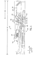
FIG. 1 , an embodiment of a gas turbine engine 100 is illustrated. The gas turbine engine 100 extends in anaxial direction 102. Aradial direction 104 illustrates a direction extending outward from an axis of the gas turbine engine 100. Further, acircumferential direction 106 illustrates the rotational direction around the axis of the gas turbine engine 100. The gas turbine engine 100 includes one ormore fuel nozzles 108 located inside a combustor section 110. In certain embodiments, the gas turbine engine 100 may includemultiple combustors 120 disposed in an annular (e.g., circumferential 106) arrangement within the combustor section 110. Further, eachcombustor 120 may includemultiple fuel nozzles 108 attached to or near a head end of eachcombustor 120 in an annular (e.g., circumferential 106) or other arrangement. - Air enters through an
air intake section 122 and is compressed by acompressor 124 of the gas turbine engine 100. The compressed air from thecompressor 124 is then directed into the combustor section 110 where the compressed air is mixed with fuel. The mixture of compressed air and fuel is generally burned within the combustor section 110 to generate high-temperature, high-pressure combustion gases, which are used to generate torque within aturbine section 130 of the gas turbine engine 100. As noted above,multiple combustors 120 may be annularly (e.g., circumferentially 106) disposed within the combustor section 110 of the gas turbine engine 100. Eachcombustor 120 includes atransition piece 172 that directs the hot combustion gases from thecombustor 120 to theturbine section 130 of the gas turbine engine 100. In particular, eachtransition piece 172 generally defines a hot gas path from thecombustor 120 to a nozzle assembly of theturbine section 130, included within afirst stage 174 of theturbine section 130 of the gas turbine engine 100. - As depicted, the
turbine section 130 includes three separate stages or sections 174 (i.e., first stage or section), 176 (i.e., second stage or section), and 178 (i.e., third stage or section, or last turbine bucket section). Although illustrated as including threestages turbine section 130 may include any number of stages. Eachstage blades 180 coupled to arotor wheel 182 rotatably attached to ashaft 184. As may be appreciated, each of theturbine blades 180 may be considered a turbine bucket, or a bucket. Eachstage nozzle assembly 186 disposed directly upstream of each set ofblades 180. The nozzle assemblies 186 direct the hot combustion gases toward theblades 180 where the hot combustion gases apply motive forces to theblades 180 to rotate theblades 180, thereby turning theshaft 184. As a result, theblades 180 andshaft 184 rotate in thecircumferential direction 106. The hot combustion gases flow through each of thestages blades 180 within eachstage gas turbine section 130 into anexhaust diffuser section 188 of the gas turbine engine 100. Theexhaust diffuser section 188 reduces the velocity of fluid flow of the exhaust combustion gases from thegas turbine section 130, and also increases the static pressure of the exhaust combustion gases to increase the work produced by the gas turbine engine 100. As illustrated, theexhaust diffuser section 188 has alength 190, which is a portion of anoverall length 192 of the gas turbine engine 100. - In the illustrated embodiment, the last
turbine bucket section 178 of theturbine section 130 includes aclearance 194 between ends of a plurality of last turbine bucket blades 195 (e.g., thelast blade 180 of the gas turbine section 130) and astationary shroud 196 disposed about the plurality of lastturbine bucket blades 195. Further, anouter wall 198 extends from thestationary shroud 196. Astrut 200 is illustrated abutting theouter wall 198.Struts 200 are used to support the structure of theexhaust diffuser section 188. The lastturbine bucket section 178 and theexhaust diffuser section 188 may be integrally designed to improve radial swirl and efficiency of the gas turbine engine 100. More specifically, as described in greater detail below, an outer wall of the lastturbine bucket section 178 may be angled with respect to a centerline of the gas turbine engine 100 at a greater angle than an outer wall of theexhaust diffuser section 188 to affect the swirling of the exhaust combustion gases from the lastturbine bucket section 178 and theexhaust diffuser section 188 to improve the efficiency of the gas turbine engine 100. -
FIG. 2 illustrates a side view of an embodiment of a last stage bucket section and a diffuser section integrated together. Anintegrated system 210 is illustrated inFIG. 2 that includes a turbine section 212 (e.g., such as thegas turbine section 130 of the gas turbine engine 100 ofFIG. 1 ) and a diffuser section 214 (e.g., theexhaust diffuser section 188 of the gas turbine engine 100 ofFIG. 1 ). As described above, in certain embodiments, theturbine section 212 and thediffuser section 214 may be part of a gas turbine engine (e.g., the gas turbine engine 100 ofFIG. 1 ). However, in other embodiments, theturbine section 212 and thediffuser section 214 may be part of other systems, such as a steam turbine engine, and so forth. - The
turbine section 212 includes anannular platform 216 extending axially 102, parallel to a centerline of theturbine section 212 and an annular casing 218 (e.g., including an annular outer wall). Theannular casing 218 circumferentially 106 surrounds theannular platform 216 to define afluid passage 220 along which fluid (e.g., the exhaust combustion gases ofFIG. 1 ) may flow from an upstreamturbine section entrance 222 to a downstreamturbine section exit 224. As illustrated, theannular casing 218 is angled with respect to theannular platform 216, and therefore, theannular casing 218 is angled with respect to the centerline of theturbine section 212. Further, although theannular casing 218 appears to extend at one angle, the angle that theannular casing 218 extends may vary and have portions with different angles, therefore, the angle that theannular casing 218 extends is quantified as an angle average α 225 (e.g., a weighted average of the different angles of theannular casing 218, weighted according to the length each angle extends). For example, in certain embodiments, the angleaverage α 225 of theannular casing 218 may be approximately 16 to 30 degrees, 17 to 24 degrees, or 19 to 23 degrees relative to theannular platform 216. Specifically, in certain embodiments, the angleaverage α 225 of theannular casing 218 may be approximately 16-25 degrees relative to theannular platform 216, and therefore relative to the centerline of theannular platform 216. Theturbine section 212 may be sequentially arranged in sections, such as with anintermediate stage section 226 and alast stage section 228, relative to a direction of fluid flow along thefluid passage 220. At each stage, an array of turbine buckets, such as an intermediatestage turbine bucket 230 and a laststage turbine bucket 232, are arrayed circumferentially 106 around theannular platform 216. - In certain embodiments, the last
stage turbine bucket 232 includes ahub 234, which is coupled to an outer radial section of theannular platform 216, anairfoil section 236 having an airfoil shape that interacts with the fluids flowing through thefluid passage 220 and extending radially 104 from thehub 234 to atip 238. Thetip 238 is disposed at a distal end of theairfoil section 236 and is proximate to an interior surface of theannular casing 218. The laststage turbine bucket 232 further includes a trailingedge 240, which is defined along an aft side of thehub 234, theairfoil section 236, and thetip 238 relative to a direction of fluid flow along thefluid passage 220. With each turbine bucket in the respective array of turbine buckets for each stage formed substantially as described above, mechanical energy can be derived from the rotation of the turbine buckets at each of the stages caused by the interaction of the fluid flowing along thefluid passage 220 with the turbine buckets. - The
diffuser section 214 is defined between acentral surface 242 extending axially 102, parallel to a centerline of thediffuser section 214, which may be an exterior facing surface of an annular diffuser central body, and adownstream diffuser section 244 of theannular casing 218. It should be noted that the centerline of theturbine section 212 and the centerline of thediffuser section 214 may be equivalent so that a continuous centerline extends through both theturbine section 212 and thediffuser section 214. As may be appreciated, thedownstream diffuser section 244 may be angled relative to thecentral surface 242. Further, although thediffuser section 244 appears to extend at one angle, the angle that thediffuser section 244 extends may vary and have portions with different angles, therefore, the angle that thediffuser section 244 extends is quantified as an angle average β 245 (e.g., a weighted average of the different angles of thediffuser section 244, weighted according to the length each angle extends). For example, in certain embodiments, the angleaverage β 245 of thedownstream diffuser section 244 may be approximately 11.50 to 14.25 degrees, 13.75 to 20.00 degrees, or 15.25 to 17.50 degrees relative to thecentral surface 242, and therefore relative to the centerline of thecentral surface 242. Specifically, in certain embodiments, the angleaverage β 245 of thedownstream section 244 may be approximately 19 degrees relative to thecentral surface 242. Thediffuser section 214 is fluidly coupled to theturbine section 212 and is disposed downstream from the trailingedge 240 of the laststage turbine bucket 232. Thus, as fluid flows over and past the trailingedge 240 of the laststage turbine bucket 232, the fluid exits theturbine section 212 and enters thediffuser section 214. Within thediffuser section 214, the fluid flows along adiffuser flow path 246 whereby the fluid flow is conditioned for further use downstream in, for example, a heat recovery steam generator (HRSG) 248. - As illustrated in
FIG. 2 , a slope of thedownstream diffuser section 244 of theannular casing 218 may be angled relative to a slope of thetip 238, which is defined axially 102 along a radially 104 distal end of thetip 238. The angling may occur at the trailingedge 240 of the laststage turbine bucket 232 or at least within about 0.5 turbine bucket chord lengths, TL, from the trailingedge 240 of the laststage turbine bucket 232. The chord length, TL, of the laststage turbine bucket 232 may, for example, be measured at thetip 238. - The sloped
downstream diffuser section 244 forms an angleaverage θ 250 with respect to the slopedtip 238. In certain embodiments, the angleaverage θ 250 may be approximately 2.00 to 10.50 degrees, 8.25 to 15.75 degrees, or 12.75 to 20.25 degrees. Specifically, in certain embodiments, the angleaverage θ 250 may be approximately 6.75 degrees. It may be appreciated that the angleaverage θ 250 is the difference between the angleaverage α 225 and the angleaverage β 245 and, therefore, the transition between theannular casing 218 relative to theannular platform 216 and thediffuser section 244 of theannular casing 218 may be angled differently by approximately the angleaverage θ 250. Further, as illustrated inFIG. 2 , the angleaverage α 225 of theannular casing 218 relative to theannular platform 216 may be greater than the angleaverage β 245 of thedownstream diffuser section 244 of theannular casing 218 relative to thecentral surface 242. In addition, theannular platform 216 and thecentral surface 242 may form an angle of approximately zero degrees relative to one another. It should be noted that there may be an outerwall transition section 252 between theannular casing 218 and thediffuser section 244. In this transition section, the outer wall transitions from the angleaverage α 225 to the angleaverage β 245. As will be appreciated, such a transition may be a single angle step transition, a curvature transition, and/or a multi-angled transition to transition between the annular casing 218 (e.g., last stage bucket outer wall) and the diffuser section 244 (e.g., diffuser section outer wall). - It should be noted that the
system 210 may be part of either a gas turbine or a steam turbine. Further, such a system may be constructed by: providing thelast stage section 228 and thediffuser section 214, as described above, and attaching bothsections -
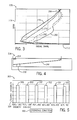
FIG. 3 illustrates agraph 270 of an amount ofradial swirl 272 that may occur in an embodiment of an integrally designed turbine system (e.g., thesystem 210 ofFIG. 2 ) under various operating conditions. The radial swirl 272 (axis x) is a number of degrees relative to a span percentage 274 (axis y). Thespan percentage 274 represents a percentage of the radial 104 area between thecentral surface 242 and thedownstream diffuser section 244 of theannular casing 218. In certain embodiments, where theradial swirl 272 axis intersects thespan percentage 274 axis, thespan percentage 274 may be approximately 0 percent. Conversely, at the opposite end of thespan percentage 274 axis, thespan percentage 274 may be approximately 100 percent. - A
first curve 276 depicts theradial swirl 272 during full speed full load (FSFL) conditions (e.g., 100 percent load), while a second curve 278 depicts theradial swirl 272 during 80 percent load conditions. Further, athird curve 280 depicts theradial swirl 272 during 60 percent load conditions, and afourth curve 282 depicts theradial swirl 272 during 40 percent load conditions. As illustrated, each of thecurves radial swirl 272 in conjunction with alow span percentage 274, then, thecurves radial swirl 272 as thespan percentage 274 approaches the maximum percentage. Specifically, thecurves location 284. In certain embodiments, theradial swirl 272 atlocation 284 may be approximately 14 to 18 degrees, 15 to 17 degrees, or 16 to 19 degrees. In particular, in certain embodiments, theradial swirl 272 atlocation 284 may be approximately 16 degrees. As may be appreciated, theradial swirl 272 may be approximately 20 to 40 percent, 30 to 50 percent, or 25 to 35 percent greater inturbine systems 210 where the laststage turbine section 228 and thediffuser section 214 are integrally designed (e.g., as described above with respect to thesystem 210 ofFIG. 2 ) as compared to turbine systems where the laststage turbine section 228 and thediffuser section 214 are designed independently. In certain embodiments, theradial swirl 272 may be approximately 33 percent greater in integrally designedsystems 210 when compared to independently designed systems. -
FIG. 4 illustrates an embodiment of thediffuser section 214 ofFIG. 2 . As illustrated, thediffuser section 214 has alength 294. In certain embodiments, thelength 294 of thediffuser section 214 may be approximately 12 to 14 m, 13 to 15 m, or 13 to 14 m. Specifically, thelength 294 of thediffuser section 214 may be approximately 13.2 m. By integrally designing the laststage turbine section 228 and thediffuser section 214, thelength 294 of thediffuser section 214 may be approximately 25 to 180 cm, 20 to 100 cm, or 50 to 80 cm shorter than asimilar diffuser section 214 in an independently designed system. Specifically, thediffuser section 214 may be approximately 30 cm shorter in an integrally designedturbine system 210 than in an independently designed system. Such a decrease in length may correspond to a decrease in length by approximately 5 to 20 percent, 10 to 30 percent, or 8 to 15 percent. Specifically, the decrease in length may correspond to a decrease in length of approximately 10 percent. Further, the decrease inlength 294 of thediffuser section 214 may be associated with a significant decrease in cost to produce thediffuser section 214. -
FIG. 5 illustrates agraph 300 showing howvarious operating conditions 302 may affectefficiency 304 that may occur in the integrally designedturbine system 210. Specifically, at FSFL and approximately -30 °C, the efficiency may be represented by abar 306. Further, at FSFL and approximately -18 °C, the efficiency may be represented by abar 308. In addition, at FSFL and ISO conditions (ISO conditions are conditions defined by the International Organization of Standardization), the efficiency may be represented by abar 310. At approximately 80 percent load and ISO conditions, the efficiency may be represented by abar 312. In particular, at approximately 60 percent load and ISO conditions, the efficiency may be represented by abar 314. Further, at approximately 40 percent load and ISO conditions, the efficiency may be represented by abar 316. - As a whole, the
bars turbine efficiency 304 remains relatively stable among the operatingconditions 302 shown. In other words, with varying temperatures and loads, theefficiency 304 remains high. In particular, at cold temperatures and low percentages of load conditions, theefficiency 304 remains high. In certain embodiments, theefficiency 304 among thebars efficiency 304 shown among thebars bar 306 may be approximately 1.5 percent greater than an independently designed system. Such an improvement in efficiency may cause an increase of approximately 5 MW of power output in the integrally designed system compared to the independently designed system. - As previously described, there may be a number of technical advantages for integrally designing components for the
turbine system 212, when compared to independently designed components. In particular, theradial swirl 272 may be increased. Further, thelength 294 of thediffuser section 212 may be reduced, which may reduce costs associated with manufacturing thediffuser section 212. In addition, theefficiency 304 of theturbine system 212 may remain high in cold and low load conditions. - This written description uses examples to disclose the invention, including the best mode, and also to enable any person skilled in the art to practice the invention, including making and using any devices or systems and performing any incorporated methods. The patentable scope of the invention is defined by the claims, and may include other examples that occur to those skilled in the art. Such other examples are intended to be within the scope of the claims if they have structural elements that do not differ from the literal language of the claims, or if they include equivalent structural elements with insubstantial differences from the literal languages of the claims.
- Various aspects and embodiments of the present invention are defined by the following numbered clauses:
- 1. A system, comprising:
- a turbine having an outer wall transition from a last stage bucket outer wall to a diffuser section outer wall, wherein the last stage bucket outer wall is angled away from a centerline of the turbine at a first angle that is greater than a second angle at which the diffuser section outer wall is angled away from the centerline of the turbine.
- 2. The system of
clause 1, wherein the first angle is greater than the second angle by approximately 2-15 degrees. - 3. The system of clause 2, wherein the first angle is greater than the second angle by approximately 6.75 degrees.
- 4. The system of
clause 1, wherein the first angle is approximately 17-30 degrees, and the second angle is approximately 12-20 degrees. - 5. The system of clause 4, wherein the first angle is approximately 22 degrees, and the second angle is approximately 17 degrees.
- 6. The system of any of
clauses 1 to 5, wherein the outer wall transition comprises a curvature to transition between the last stage bucket outer wall and the diffuser section outer wall. - 7. The system of any of
clauses 1 to 5, wherein the outer wall transition comprises multiple angles to transition between the last stage bucket outer wall and the diffuser section outer wall.
Claims (13)
- A system (210), comprising:a turbine (212), comprising:a last stage bucket section having (232) a first annular outer wall (218) that is angled with respect to a centerline of the turbine (212) at a first angle average (225); anda diffuser section (214) having a second annular outer wall (244) that is angled with respect to the centerline of the turbine (212) at a second angle average (245) for improving radial swirl (272), wherein the first angle average (225) is greater than the second angle average (245).
- The system of claim 1, wherein the first angle average (225) is greater than the second angle average (245) by approximately 2-15 degrees.
- The system of claim 2, wherein the first angle average (225) is greater than the second angle average (245) by approximately 6.75 degrees.
- The system of claim 1, wherein the first angle average (225) is approximately 17-30 degrees.
- The system of claim 4, wherein the first angle average (225) is approximately 25 degrees.
- The system of claim 1, wherein the second angle average (245) is approximately 12-20 degrees.
- The system of claim 6, wherein the second angle average (245) is approximately 19 degrees.
- The system of any preceding claim, wherein the turbine (212) is a gas turbine (100).
- The system of claim 1, wherein the turbine (212) is a steam turbine (100).
- A method, comprising:providing a last stage bucket section (232) of a turbine (212) that is outwardly angled with respect to an axial centerline of the last stage bucket section (232) from a first axial end of the last stage bucket section (232) to a second axial end of the last stage bucket section (232) at a substantially constant first angle (225);providing a diffuser section (214) of the turbine (212) that is outwardly angled with respect to an axial centerline of the diffuser section (214) at a first axial end of the diffuser section (214) at a second angle (245), wherein the first angle (225) is greater than the second angle (245); andattaching the second axial end of the last stage bucket section (232) to the first axial end of the diffuser section (214).
- The method of claim 10, comprising providing the last stage bucket section (232) that is outwardly angled at the substantially constant first angle (225) that is approximately 2-15 degrees greater than the second angle (245) at which the diffuser section (214) is outwardly angled.
- The method of claim 10, comprising providing the last stage bucket section (232) that is outwardly angled at the substantially constant first angle (225) of approximately 17-30 degrees, and providing the diffuser section (214) that is outwardly angled at the second angle of approximately 12-20 degrees.
- The method of claim 12, comprising providing the last stage bucket section (232) that is outwardly angled at the substantially constant first angle (225) of approximately 22 degrees, and providing the diffuser section (214) that is outwardly angled at the second angle (245) of approximately 17 degrees.
Applications Claiming Priority (1)
| Application Number | Priority Date | Filing Date | Title |
|---|---|---|---|
| US13/277,972 US9284853B2 (en) | 2011-10-20 | 2011-10-20 | System and method for integrating sections of a turbine |
Publications (2)
| Publication Number | Publication Date |
|---|---|
| EP2584156A2 true EP2584156A2 (en) | 2013-04-24 |
| EP2584156A3 EP2584156A3 (en) | 2017-06-28 |
Family
ID=47115389
Family Applications (1)
| Application Number | Title | Priority Date | Filing Date |
|---|---|---|---|
| EP12188815.0A Withdrawn EP2584156A3 (en) | 2011-10-20 | 2012-10-17 | System and method for integrating sections of a turbine |
Country Status (3)
| Country | Link |
|---|---|
| US (1) | US9284853B2 (en) |
| EP (1) | EP2584156A3 (en) |
| CN (1) | CN103061831B (en) |
Families Citing this family (3)
| Publication number | Priority date | Publication date | Assignee | Title |
|---|---|---|---|---|
| US9598981B2 (en) * | 2013-11-22 | 2017-03-21 | Siemens Energy, Inc. | Industrial gas turbine exhaust system diffuser inlet lip |
| US9644497B2 (en) * | 2013-11-22 | 2017-05-09 | Siemens Energy, Inc. | Industrial gas turbine exhaust system with splined profile tail cone |
| JP6498534B2 (en) * | 2015-06-09 | 2019-04-10 | 川崎重工業株式会社 | Exhaust diffuser |
Family Cites Families (18)
| Publication number | Priority date | Publication date | Assignee | Title |
|---|---|---|---|---|
| NL87380C (en) * | 1950-03-27 | |||
| US3625630A (en) * | 1970-03-27 | 1971-12-07 | Caterpillar Tractor Co | Axial flow diffuser |
| US4550562A (en) * | 1981-06-17 | 1985-11-05 | Rice Ivan G | Method of steam cooling a gas generator |
| EP0417433B1 (en) * | 1989-09-12 | 1993-06-09 | Asea Brown Boveri Ag | Axial turbine |
| US5301500A (en) * | 1990-07-09 | 1994-04-12 | General Electric Company | Gas turbine engine for controlling stall margin |
| DE59204947D1 (en) * | 1992-08-03 | 1996-02-15 | Asea Brown Boveri | Multi-zone diffuser for turbomachinery |
| DE4232088A1 (en) * | 1992-09-25 | 1994-03-31 | Asea Brown Boveri | Gas turbine with exhaust housing and exhaust duct |
| US6488470B1 (en) | 1999-08-03 | 2002-12-03 | Jerzy A. Owczarek | Annular flow diffusers for gas turbines |
| JP3912989B2 (en) | 2001-01-25 | 2007-05-09 | 三菱重工業株式会社 | gas turbine |
| JP3564420B2 (en) * | 2001-04-27 | 2004-09-08 | 三菱重工業株式会社 | gas turbine |
| US20040109756A1 (en) | 2002-12-09 | 2004-06-10 | Mitsubishi Heavy Industries Ltd. | Gas turbine |
| GB2415749B (en) * | 2004-07-02 | 2009-10-07 | Demag Delaval Ind Turbomachine | A gas turbine engine including an exhaust duct comprising a diffuser for diffusing the exhaust gas produced by the engine |
| EP1970539A1 (en) * | 2007-03-13 | 2008-09-17 | Siemens Aktiengesellschaft | Diffuser assembly |
| US8313286B2 (en) * | 2008-07-28 | 2012-11-20 | Siemens Energy, Inc. | Diffuser apparatus in a turbomachine |
| US8146341B2 (en) * | 2008-09-22 | 2012-04-03 | General Electric Company | Integrated gas turbine exhaust diffuser and heat recovery steam generation system |
| JP5812567B2 (en) * | 2010-02-16 | 2015-11-17 | 三菱日立パワーシステムズ株式会社 | Turbine |
| US8591184B2 (en) * | 2010-08-20 | 2013-11-26 | General Electric Company | Hub flowpath contour |
| US9249687B2 (en) * | 2010-10-27 | 2016-02-02 | General Electric Company | Turbine exhaust diffusion system and method |
-
2011
- 2011-10-20 US US13/277,972 patent/US9284853B2/en active Active
-
2012
- 2012-10-17 EP EP12188815.0A patent/EP2584156A3/en not_active Withdrawn
- 2012-10-19 CN CN201210400869.6A patent/CN103061831B/en active Active
Non-Patent Citations (1)
| Title |
|---|
| None |
Also Published As
| Publication number | Publication date |
|---|---|
| CN103061831A (en) | 2013-04-24 |
| EP2584156A3 (en) | 2017-06-28 |
| US9284853B2 (en) | 2016-03-15 |
| US20130101387A1 (en) | 2013-04-25 |
| CN103061831B (en) | 2016-08-24 |
Similar Documents
| Publication | Publication Date | Title |
|---|---|---|
| EP3244011B1 (en) | System for cooling seal rails of tip shroud of turbine blade | |
| US20120034064A1 (en) | Contoured axial-radial exhaust diffuser | |
| EP2586976B1 (en) | Turbine for a turbomachine | |
| US10830082B2 (en) | Systems including rotor blade tips and circumferentially grooved shrouds | |
| EP2204534B1 (en) | Turbine airfoil clocking | |
| US20100054929A1 (en) | Turbine airfoil clocking | |
| US10273976B2 (en) | Actively morphable vane | |
| EP2586979B1 (en) | Turbomachine blade with tip flare | |
| CN112943377B (en) | Damper stacks for turbine rotor blades | |
| WO2019027661A1 (en) | Gas turbine exhaust diffuser having flow guiding elements | |
| WO2014078370A1 (en) | An exhaust gas diffuser for a gas turbine | |
| CN113446068B (en) | Cooling circuit for turbine components | |
| US9284853B2 (en) | System and method for integrating sections of a turbine | |
| EP3168416B1 (en) | Gas turbine | |
| US20180371921A1 (en) | Turbomachine rotor blade | |
| US20100054922A1 (en) | Turbine airfoil clocking | |
| US20190390688A1 (en) | Gas turbine engine airfoil | |
| EP3828386B1 (en) | Turbomachine rotor blade having a variable elliptical trailing edge | |
| EP3828390B1 (en) | Turbomachine nozzle with an airfoil having a curvilinear trailing edge | |
| US11536144B2 (en) | Rotor blade damping structures | |
| US11066935B1 (en) | Rotor blade airfoil | |
| US20210301667A1 (en) | Turbomachine rotor blade with a cooling circuit having an offset rib | |
| US20250283415A1 (en) | Turbine engine with a blade assembly having a set of cooling conduits |
Legal Events
| Date | Code | Title | Description |
|---|---|---|---|
| PUAI | Public reference made under article 153(3) epc to a published international application that has entered the european phase |
Free format text: ORIGINAL CODE: 0009012 |
|
| AK | Designated contracting states |
Kind code of ref document: A2 Designated state(s): AL AT BE BG CH CY CZ DE DK EE ES FI FR GB GR HR HU IE IS IT LI LT LU LV MC MK MT NL NO PL PT RO RS SE SI SK SM TR |
|
| AX | Request for extension of the european patent |
Extension state: BA ME |
|
| PUAL | Search report despatched |
Free format text: ORIGINAL CODE: 0009013 |
|
| AK | Designated contracting states |
Kind code of ref document: A3 Designated state(s): AL AT BE BG CH CY CZ DE DK EE ES FI FR GB GR HR HU IE IS IT LI LT LU LV MC MK MT NL NO PL PT RO RS SE SI SK SM TR |
|
| AX | Request for extension of the european patent |
Extension state: BA ME |
|
| RIC1 | Information provided on ipc code assigned before grant |
Ipc: F01D 25/30 20060101AFI20170523BHEP |
|
| STAA | Information on the status of an ep patent application or granted ep patent |
Free format text: STATUS: REQUEST FOR EXAMINATION WAS MADE |
|
| 17P | Request for examination filed |
Effective date: 20180102 |
|
| RBV | Designated contracting states (corrected) |
Designated state(s): AL AT BE BG CH CY CZ DE DK EE ES FI FR GB GR HR HU IE IS IT LI LT LU LV MC MK MT NL NO PL PT RO RS SE SI SK SM TR |
|
| STAA | Information on the status of an ep patent application or granted ep patent |
Free format text: STATUS: EXAMINATION IS IN PROGRESS |
|
| 17Q | First examination report despatched |
Effective date: 20190325 |
|
| STAA | Information on the status of an ep patent application or granted ep patent |
Free format text: STATUS: THE APPLICATION IS DEEMED TO BE WITHDRAWN |
|
| 18D | Application deemed to be withdrawn |
Effective date: 20210316 |