EP2583603A1 - Portable sheet product dispenser - Google Patents
Portable sheet product dispenser Download PDFInfo
- Publication number
- EP2583603A1 EP2583603A1 EP11008479.5A EP11008479A EP2583603A1 EP 2583603 A1 EP2583603 A1 EP 2583603A1 EP 11008479 A EP11008479 A EP 11008479A EP 2583603 A1 EP2583603 A1 EP 2583603A1
- Authority
- EP
- European Patent Office
- Prior art keywords
- sheet product
- container
- housing
- opening
- dispenser
- Prior art date
- Legal status (The legal status is an assumption and is not a legal conclusion. Google has not performed a legal analysis and makes no representation as to the accuracy of the status listed.)
- Withdrawn
Links
Images


Classifications
-
- A—HUMAN NECESSITIES
- A47—FURNITURE; DOMESTIC ARTICLES OR APPLIANCES; COFFEE MILLS; SPICE MILLS; SUCTION CLEANERS IN GENERAL
- A47K—SANITARY EQUIPMENT; ACCESSORIES THEREFOR, e.g. TOILET ACCESSORIES
- A47K10/00—Body-drying implements; Toilet paper; Holders therefor
- A47K10/24—Towel dispensers; Toilet paper dispensers
- A47K10/32—Dispensers for paper towels or toilet paper
- A47K10/34—Dispensers for paper towels or toilet paper dispensing from a web, e.g. with mechanical dispensing means
- A47K10/38—Dispensers for paper towels or toilet paper dispensing from a web, e.g. with mechanical dispensing means the web being rolled-up
- A47K10/3809—Dispensers for paper towels or toilet paper dispensing from a web, e.g. with mechanical dispensing means the web being rolled-up with roll spindles which are not directly supported
- A47K10/3818—Dispensers for paper towels or toilet paper dispensing from a web, e.g. with mechanical dispensing means the web being rolled-up with roll spindles which are not directly supported with a distribution opening which is perpendicular to the rotation axis
-
- A—HUMAN NECESSITIES
- A47—FURNITURE; DOMESTIC ARTICLES OR APPLIANCES; COFFEE MILLS; SPICE MILLS; SUCTION CLEANERS IN GENERAL
- A47K—SANITARY EQUIPMENT; ACCESSORIES THEREFOR, e.g. TOILET ACCESSORIES
- A47K10/00—Body-drying implements; Toilet paper; Holders therefor
- A47K10/24—Towel dispensers; Toilet paper dispensers
- A47K10/32—Dispensers for paper towels or toilet paper
- A47K2010/3206—Coreless paper rolls
Definitions
- An aspect of the invention relates to sheet product dispensers and in particular to portable sheet product dispensers with a dispensing opening. Such dispensers find a particular, though non exclusive, application in dispensing sheet products.
- Portable sheet product dispensers are well known in the art. Portable sheet product dispensers are generally used for dispensing sheet products such as absorbent tissues, wipes, paper towels or sheets made of any other absorbent or non-absorbent material.
- document WO 2006/009859 discloses a water-resistant absorbent towel dispenser including a container with an exterior handle. A top side includes a finger-accessible opening through which absorbent towels may be withdrawn.
- the top wall of the dispenser may be convex in an upward direction but is flexible to enable it to be depressed when two or more dispensers are stacked vertically so as to come into load bearing contact with the towel supply.
- a container for storing a sheet product is disclosed.
- the container housing is substantially cylindrical and the outer surface has a retention formation configured to engage an attachment apparatus.
- a lid portion of the container includes a sheet product retainer to prevent a partially dispensed sheet product from falling back into the container.
- the lid portion includes a retention tap configured to prevent a lid of the lid portion from separating completely from the container.
- Document WO 2008/025980 discloses a container for dispensing wipes through a dispensing nozzle.
- the container has a housing for accommodating a source of wipes.
- a dispensing nozzle On one end of the housing a dispensing nozzle is provided which is formed with a resilient aperture through which wipes can be withdrawn from the housing.
- the resilient aperture is expandable to allow withdrawal of wipes therethrough but is biased towards a contracted state.
- a wipe can be withdrawn through the dispensing nozzle and be separated by rupturing the perforation connecting the wipe to the next adjacent wipe with the nozzle expanding as required to allow passage of the wipe through the nozzle aperture.
- the portable dispenser is compact to gain space during delivery and transportation.
- a portable sheet product dispenser for dispensing a strip of a sheet product.
- the dispenser comprises:
- the portable sheet product dispenser is to provide a separately formed dispensing piece which can be attached to the container.
- the dispensing piece is configured to be inserted into an opening, such that the dispensing piece protrudes either inwardly into or outwardly from the container.
- the dispensing piece protrudes in an outward direction from the container of the portable sheet product dispenser.
- the portable sheet product dispenser can be used for withdrawal of sheet products.
- the dispensing piece protrudes inwardly into the housing. This allows two dispensers being vertically stacked onto each another.
- the container may include a cylindrical housing with a loading opening for loading a source of sheet product and a closure element for closing the loading opening of the housing, wherein the closure element is attachable onto the housing so that it can be removed for loading the source of sheet product into the container.
- the opening of the container may be provided in the closure element.
- the cylindrical housing may have an open end which forms the opening, wherein the closure element is configured to close the one end, wherein the closure element has a planar outer surface which is perpendicular to the axis of the cylindrical housing when attached to the housing.
- the dispensing piece may have a base portion to be inserted into the opening with two orientations so that the base portion is held into the opening in form-fit or force-fit manner.
- the dispenser may be loaded with a sheet roll as the source of sheet product, wherein the sheet roll is a coreless centerfeed roll, wherein the housing has means configured to hold the sheet roll in a press-fit manner.
- the housing may have one of a concave bottom part at one end opposite to the loading opening, an indentation of a side wall of the housing and an angular shape, in particular a hexagonal shape.
- a handle may be attached at the container, wherein the handle is L-shaped so that one leg of the handle is in parallel with a side wall of the cylindrical housing. This allows an easy handling of the dispenser and further the dispenser can be hooked onto vertical arranged boards and the like if a free hand is needed.
- a support hole may be provided to allow insertion of a downwardly oriented handle of a spray bottle.
- the support hole may be formed outside a circumferential edge of the container.
- an arrangement comprises a wall holder with a base part for mounting at a wall and two arms extending from the base part and the above portable sheet product dispenser, wherein the housing has a circumferential edge which has two opposite grooves, wherein the arms are configured to receive the circumferential edge so that the arms engage the grooves and the portable sheet product dispenser is supported by the wall holder.
- the arms may be biased so that they are pressed toward the circumferential edge when the portable sheet product dispenser is held between the arms.
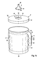
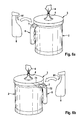
- Figures 1 a and 1b illustrate a portable sheet product dispenser in a perspective view and in an explosion view, respectively.
- the dispenser 1 has a container with a cylindrical housing 2 which has a side wall 21 and a bottom portion 22 which closes a first end of the cylindrical housing 2.
- a second end of the cylindrical housing 2 is open and can be closed by a lid 3 or cover, respectively (closure element), to form a closed container for storing a source of a sheet product.
- the side wall 21 and the bottom portion 22 of the housing 2 can be formed as an integral element, i.e. by known molding and extrusion techniques.
- the housing 2 may include a center portion 23 that is recessed relative to the bottom portion 22 and a portion close to the second end.
- the center portion 23 may have a smooth surface or may be embossed with lettering and/or design for decorative or marketing purposes.
- the lid 3 is formed as a separate element and can be attached to the second end of the housing 2, such that it closes the respective end of the housing 2 to form the container.
- the lid 3 has a substantially planar lid surface 32 which is perpendicular to the longitudinal axis of the cylindrical housing 2.
- the lid surface 32 is encompassed by a circumferential edge 31 which extends perpendicular from the lid surface 32.
- the circumferential edge 31 defines an inner cross-section which is slightly larger than the outer cross-sectional area of the cylindrical housing such that the lid 3 can be attached onto the housing 2.
- the lid 3 may be attached to the housing 2 in various manners. For instance, it may be attached through the use of a peripheral outer thread 25 close to the second end of the housing 2 and a corresponding inner thread (not shown) in the circumferential edge 31 of the lid 3. Alternatively, the lid 3 may be attached to the housing 2 by the use of complementary circumferential grooves and beads enabling the circumferential edge 31 of the lid 3 to be snapped onto the side wall 21 of the housing 2. Other alternatives to attach the lid 3 onto the housing 2 can be thought of.
- the lid 3 can be removed so that the interior of the housing 2 is fully opened for loading with a source of a sheet product, such as a sheet roll 5.
- the sheet roll 5 may be made of absorbent or non-absorbent material of a woven or non-woven type.
- the sheets may be used as wipes, paper towels, toilet paper, cleaning tissues and the like.
- the individual sheets may be sized as desired to accommodate the many uses of the towels.
- perforation lines may be formed to allow the user to tear off a sheet after the perforation line has left the dispensing piece 4.
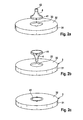
- an opening 33 is provided to receive a dispensing piece 4 which is formed as a separate element.
- the dispensing piece 4 is shown as a substantially cone-shaped nozzle. However different shapes and designs of the dispensing piece are possible. It has been found that dispensing pieces that protrudes from the lid surface allow a greater degree of angles to withdraw the sheet product from the dispenser so that the use of such a dispenser is greatly improved.
- the dispensing piece 4 is formed as a cone-shaped dispensing nozzle with its outer side surface being concave-shaped.
- the dispensing piece 4 includes a base portion 41 by which the dispensing piece 4 can be inserted into the opening 33 of the lid 3 to be held therein.
- the dispensing piece 4 has a dispensing opening 42 at an end opposite from the base portion 41 through which the sheets of the sheet product can be withdrawn.
- the base portion 41 has a shape that allows it to be held within the lid opening 33, so that the lid surface 32 and the base portion 41 are substantially arranged in a coplanar manner.
- the base portion 41 is provided with one or more noses 43 that can be inserted into respective grooves 34 of the lid 3 at the edge of the lid opening 33.
- the grooves 34 substantially extend in an axial direction of the housing 2 from the lid surface 32 until respective stops 35, so that the noses 43 are stopped at the stops 35 when the dispensing piece 4 is inserted into the lid opening 33.
- the stops 35 serve to prevent the dispensing piece 4 from being pushed into the interior of the container.
- the noses 43 and the grooves 34 are configured to provide a form-fit or force-fit attachment, so that the dispensing piece 4 provides a securely mounted dispensing opening 42 for the dispenser 1, when in use without being removed from the lid opening 33 when a sheet is withdrawn from the dispenser 1.
- the mounting arrangement is configured so that the dispensing piece 4 can only be removed from the lid opening 33 when a specific pulling force is applied onto it.
- the noses 43 are arranged at the circumferential edge of the base portion 41 in a symmetrical manner.
- the grooves 34 at the edge of the lid opening 33 are arranged correspondingly, so that each nose 43 can be put into a respective groove 34.
- the dispensing piece 4 can be inserted into the lid opening 33 such that the cone-shaped dispensing piece 4 protrudes outwardly from the lid 3 in a dispensing state ( Fig. 2a ) and can be inserted into the lid opening 3 such that the dispensing nozzle 4 protrudes inwardly into the housing 2 ( Fig. 2b ), so that no protrusion on the lid surface 32 remains ( Fig. 2c ) and a planar surface is obtained.
- the dispensing piece 4 In a transportation state, the dispensing piece 4 is inserted into the lid opening 33 as shown in Fig. 2c , so that the dispensing piece 4 protrudes inwardly into the housing 2 and provides a substantially planar surface of the lid 3.
- the dispensers 1 can be vertically stacked onto one another by placing a bottom portion 22 of one dispenser 1 onto the planar surface of another dispenser 1.
- the vertical stacking of dispensers may be useful for a space efficient storing in packing boxes for storage, shipment and display.
- the housing 2 as depicted on Figs. 1 a and 1b is provided with a handle 6 to facilitate transport and use of the dispenser 1.
- the handle 6 is formed to extend beyond the side surface of the housing 2.
- the handle 6 has an L-shape with a short leg 61 and a long leg 62, wherein the short leg 61 is integrally attached to the housing 2 preferably close to the thread 25 by means of which the lid 3 is to be attached.
- the long leg 62 may be of a tubular shape.
- the long leg 62 is spaced from the side wall 21 of the housing 2 and substantially extends in parallel thereto along the axial direction of the cylindrical housing 2.
- the distance between the side wall 21 of the housing 2 and the long leg 62 is set such that the long leg 62 can be gripped by hand.
- the long leg 62 can be provided with indentations 63 opposite the side wall 21 for fingers to grasp.
- the distance between the side wall 21 of the housing 2 and the long leg 62 of the handle 6 may range from about 1.5 to 3 cm.
- the end of the long leg 62 remote from the short leg 61 is open, i.e. not attached to the housing 2. Hence, it facilitates hanging the dispenser 1 onto a substantially vertical board or plate-like object just by inserting an upper edge of the board between the long leg 62 of the handle 6 and the housing 2. Furthermore, the "open" handle 6 allows the cylindrical side wall 21 of the housing 2 to be simply provided with a printed label already supplied in a closed ring by shifting it from the bottom portion 22 over the cylindrical housing 2.
- a sheet roll as the sheet source is put into the open housing 2.
- the sheet roll 5 is preferably a paper roll, in particular a center-feed roll, wherein the roll 5 is not provided with a central core, so that a free end in the center portion of the roll 5 is accessible.
- the sheet roll 5 is positioned with its axis extending coaxially with the axis of the cylindrical housing 2.
- the sheet roll 5 is dispensed from its center to its circumference.
- the sheet roll 5 may be of any size to fit within the housing 2 of the dispenser 1.
- Fig. 3b to guide the free end through the dispensing opening 42 it can be fed firstly through the lid opening 33 before the lid 3 is attached onto the housing 2. After the lid 3 is then attached to the housing 2, the free end of the strip 51 is then fed through the dispensing piece 4 from the base portion 41 to the dispensing opening 42.
- figures 4a to 4c show different structuring of the housing 2 which allow fixing of the sheet roll 5 within the housing 2.
- the bottom portion 22 can be arranged outwardly concave, so that a center part of the bottom portion 22 is pressed onto one end of the cylindrical sheet roll 5 inside the housing 2 thereby holding the sheet roll 5 between the bottom portion 22 and the lid 3. This supports the sheet product such that a collapsing of the sheet roll 5 is prevented.
- recesses 26 and indentations can be provided in the side wall 21 of the housing 2 that protrude inwardly and provide an inner diameter or cross-section of the housing 2, respectively, that is equal to or less than the diameter of the sheet roll 5 to be inserted, so that the sheet roll 5 is compressed and thereby held securely within the housing 2.
- Figure 4c shows a cylindrical housing 2 having an angular e.g. hexagonal cross-section, so that side planes are formed which are configured to press against the outer circumference of the sheet roll 5 thereby holding the sheet roll 5 in place.
- the housing 2 is preferably made of plastic and can be manufactured by blow molding, injection molding and the like and may be formed with the handle 6 as an integral product to increase the water tightness of the dispenser 1.
- the lid 3 may be molded separately and may be made of the same or similar materials as the housing 2.
- a wall holder 10 can be provided which can be attached to a wall and which provides a base part 12 and two support arms 11 which extend substantially perpendicular from the base part 12 of the dispenser holder 10.
- the circumferential edge 31 of the lid 3 may have at least two opposite concave-shaped portions or has an encompassing concave-shaped groove.
- the support arms 11 are configured such that the dispenser 1 can be attached by pushing the lid 3 between the two support arms 11 ( Fig. 5a ).
- the support arms 11 are biased against the lid 3 so that the support arms 11 are widened and the lid 3 is accommodated between the arms 11.
- the arms 11 are then held within the concave groove around the circumferential edge 31 of the lid 3 and prevent the dispenser 1 from falling out of the wall holder 10.
- the dispenser 1 When the dispenser 1 is pushed onto the wall holder 10 in a bottom-up position ( Fig. 5b ), the dispensing piece 4 protrudes downward from the lid 3, so that a wall-supported dispenser 1 can be obtained which allows for withdrawing sheets without the need to have the dispenser 1 grasped all the time.
- the wall holder 10 allows removal and replacement of the dispenser 1 at will.
- a support hole 7 can be provided to hold e.g. a spray bottle 8 at the dispenser 1.
- the spray bottle 8 usually has a spray bottle handle 81 which can be inserted into the support hole 7 so that by grasping the dispenser 1 the spray bottle 8 can also be carried without using an extra hand. Also the spray bottle 8 can be easily removed for use.
- the support hole 7 can be either included in the handle 6 wherein on the upper side of the short leg 61 a circular opening is formed in which the spray bottle handle 81 can be inserted.
- a ring element 72 can be provided which protrudes sideways from the lid 3 e.g. by means of a beam 71 connecting the ring element 72 and the lid 3.
- the lid 3, beam 71 and ring element 72 can be integrally formed.
Landscapes
- Health & Medical Sciences (AREA)
- Public Health (AREA)
- Details Of Rigid Or Semi-Rigid Containers (AREA)
- Containers And Packaging Bodies Having A Special Means To Remove Contents (AREA)
Abstract
Description
- An aspect of the invention relates to sheet product dispensers and in particular to portable sheet product dispensers with a dispensing opening. Such dispensers find a particular, though non exclusive, application in dispensing sheet products.
- Portable sheet product dispensers are well known in the art. Portable sheet product dispensers are generally used for dispensing sheet products such as absorbent tissues, wipes, paper towels or sheets made of any other absorbent or non-absorbent material.
- For example, document
WO 2006/009859 discloses a water-resistant absorbent towel dispenser including a container with an exterior handle. A top side includes a finger-accessible opening through which absorbent towels may be withdrawn. The top wall of the dispenser may be convex in an upward direction but is flexible to enable it to be depressed when two or more dispensers are stacked vertically so as to come into load bearing contact with the towel supply. - In document
US 2009/0302052 a container for storing a sheet product is disclosed. The container housing is substantially cylindrical and the outer surface has a retention formation configured to engage an attachment apparatus. A lid portion of the container includes a sheet product retainer to prevent a partially dispensed sheet product from falling back into the container. The lid portion includes a retention tap configured to prevent a lid of the lid portion from separating completely from the container. - Document
WO 2008/025980 discloses a container for dispensing wipes through a dispensing nozzle. The container has a housing for accommodating a source of wipes. On one end of the housing a dispensing nozzle is provided which is formed with a resilient aperture through which wipes can be withdrawn from the housing. The resilient aperture is expandable to allow withdrawal of wipes therethrough but is biased towards a contracted state. In use a wipe can be withdrawn through the dispensing nozzle and be separated by rupturing the perforation connecting the wipe to the next adjacent wipe with the nozzle expanding as required to allow passage of the wipe through the nozzle aperture. - However, these dispensers are not satisfactory because withdrawal of a sheet product is uneasy, and/or they are bulky.
- It is an object of the present invention to propose a portable sheet product dispenser that overcomes the above mentioned drawbacks. In particular, it is an object of the present invention to provide a portable sheet product dispenser having a dispensing opening for facilitating withdrawal of a sheet product. Furthermore, it is an object of the present invention that the portable dispenser is compact to gain space during delivery and transportation.
- According to one aspect, a portable sheet product dispenser for dispensing a strip of a sheet product is provided. The dispenser comprises:
- a container for accommodating a source of sheet product;
- a dispensing piece to be removably inserted into an opening of the container in at least two different states,
- One idea of the portable sheet product dispenser is to provide a separately formed dispensing piece which can be attached to the container. The dispensing piece is configured to be inserted into an opening, such that the dispensing piece protrudes either inwardly into or outwardly from the container. In a dispensing state, the dispensing piece protrudes in an outward direction from the container of the portable sheet product dispenser. In the dispensing state, the portable sheet product dispenser can be used for withdrawal of sheet products. In another transportation state, the dispensing piece protrudes inwardly into the housing. This allows two dispensers being vertically stacked onto each another.
- Further, the container may include a cylindrical housing with a loading opening for loading a source of sheet product and a closure element for closing the loading opening of the housing, wherein the closure element is attachable onto the housing so that it can be removed for loading the source of sheet product into the container. In particular, the opening of the container may be provided in the closure element.
- Furthermore, the cylindrical housing may have an open end which forms the opening, wherein the closure element is configured to close the one end, wherein the closure element has a planar outer surface which is perpendicular to the axis of the cylindrical housing when attached to the housing.
- Moreover, the dispensing piece may have a base portion to be inserted into the opening with two orientations so that the base portion is held into the opening in form-fit or force-fit manner.
- The dispenser may be loaded with a sheet roll as the source of sheet product, wherein the sheet roll is a coreless centerfeed roll, wherein the housing has means configured to hold the sheet roll in a press-fit manner.
- Particularly, the housing may have one of a concave bottom part at one end opposite to the loading opening, an indentation of a side wall of the housing and an angular shape, in particular a hexagonal shape.
- A handle may be attached at the container, wherein the handle is L-shaped so that one leg of the handle is in parallel with a side wall of the cylindrical housing. This allows an easy handling of the dispenser and further the dispenser can be hooked onto vertical arranged boards and the like if a free hand is needed.
- A support hole may be provided to allow insertion of a downwardly oriented handle of a spray bottle. In particular, the support hole may be formed outside a circumferential edge of the container.
- According to another aspect, an arrangement is provided that comprises a wall holder with a base part for mounting at a wall and two arms extending from the base part and the above portable sheet product dispenser, wherein the housing has a circumferential edge which has two opposite grooves, wherein the arms are configured to receive the circumferential edge so that the arms engage the grooves and the portable sheet product dispenser is supported by the wall holder.
- Moreover, the arms may be biased so that they are pressed toward the circumferential edge when the portable sheet product dispenser is held between the arms.
- The present invention is illustrated by way of examples and not limited to the accompanying drawings, in which like references indicate similar elements:
-
Figures 1 a and 1b show a perspective and an explosion view of a portable sheet product dispenser, respectively; -
Figures 2a to 2c shows illustrations of the insertion of the dispensing piece into the lid opening in different states; -
Figures 3a and3b show the process of loading the portable sheet product dispenser with a sheet source; -
Figures 4a to 4c show measures to hold the sheet roll within the housing of the portable sheet product dispenser; -
Figures 5a and 5b show a wall mount for the portable sheet product dispenser to use the portable dispenser as a fixed dispenser with a bottom-side dispensing nozzle; and -
Figures 6a and 6b show further embodiments of the portable sheet product dispenser with means for holding a spray bottle. - The following detailed description should be read with reference to the drawings. The drawings depict exemplary embodiments and are not intended to limit the scope of the invention.
-
Figures 1 a and 1b illustrate a portable sheet product dispenser in a perspective view and in an explosion view, respectively. - The dispenser 1 has a container with a
cylindrical housing 2 which has aside wall 21 and abottom portion 22 which closes a first end of thecylindrical housing 2. A second end of thecylindrical housing 2 is open and can be closed by alid 3 or cover, respectively (closure element), to form a closed container for storing a source of a sheet product. - The
side wall 21 and thebottom portion 22 of thehousing 2 can be formed as an integral element, i.e. by known molding and extrusion techniques. Thehousing 2 may include acenter portion 23 that is recessed relative to thebottom portion 22 and a portion close to the second end. Thecenter portion 23 may have a smooth surface or may be embossed with lettering and/or design for decorative or marketing purposes. - The
lid 3 is formed as a separate element and can be attached to the second end of thehousing 2, such that it closes the respective end of thehousing 2 to form the container. Thelid 3 has a substantiallyplanar lid surface 32 which is perpendicular to the longitudinal axis of thecylindrical housing 2. Thelid surface 32 is encompassed by acircumferential edge 31 which extends perpendicular from thelid surface 32. Substantially, thecircumferential edge 31 defines an inner cross-section which is slightly larger than the outer cross-sectional area of the cylindrical housing such that thelid 3 can be attached onto thehousing 2. - The
lid 3 may be attached to thehousing 2 in various manners. For instance, it may be attached through the use of a peripheralouter thread 25 close to the second end of thehousing 2 and a corresponding inner thread (not shown) in thecircumferential edge 31 of thelid 3. Alternatively, thelid 3 may be attached to thehousing 2 by the use of complementary circumferential grooves and beads enabling thecircumferential edge 31 of thelid 3 to be snapped onto theside wall 21 of thehousing 2. Other alternatives to attach thelid 3 onto thehousing 2 can be thought of. - The
lid 3 can be removed so that the interior of thehousing 2 is fully opened for loading with a source of a sheet product, such as asheet roll 5. Thesheet roll 5 may be made of absorbent or non-absorbent material of a woven or non-woven type. The sheets may be used as wipes, paper towels, toilet paper, cleaning tissues and the like. The individual sheets may be sized as desired to accommodate the many uses of the towels. Furthermore, perforation lines may be formed to allow the user to tear off a sheet after the perforation line has left the dispensingpiece 4. - In the center of the
lid surface 31 of thelid 3, anopening 33 is provided to receive adispensing piece 4 which is formed as a separate element. The dispensingpiece 4 is shown as a substantially cone-shaped nozzle. However different shapes and designs of the dispensing piece are possible. It has been found that dispensing pieces that protrudes from the lid surface allow a greater degree of angles to withdraw the sheet product from the dispenser so that the use of such a dispenser is greatly improved. - As shown in the
Figs 1 a and 1b, the dispensingpiece 4 is formed as a cone-shaped dispensing nozzle with its outer side surface being concave-shaped. The dispensingpiece 4 includes abase portion 41 by which thedispensing piece 4 can be inserted into theopening 33 of thelid 3 to be held therein. Furthermore, the dispensingpiece 4 has a dispensingopening 42 at an end opposite from thebase portion 41 through which the sheets of the sheet product can be withdrawn. Thebase portion 41 has a shape that allows it to be held within thelid opening 33, so that thelid surface 32 and thebase portion 41 are substantially arranged in a coplanar manner. - In order to fixate the
dispensing piece 4 in thelid opening 33, a mounting arrangement is provided. In the present embodiments, thebase portion 41 is provided with one ormore noses 43 that can be inserted intorespective grooves 34 of thelid 3 at the edge of thelid opening 33. Thegrooves 34 substantially extend in an axial direction of thehousing 2 from thelid surface 32 until respective stops 35, so that thenoses 43 are stopped at thestops 35 when thedispensing piece 4 is inserted into thelid opening 33. The stops 35 serve to prevent thedispensing piece 4 from being pushed into the interior of the container. - It may be provided that the
noses 43 and thegrooves 34 are configured to provide a form-fit or force-fit attachment, so that the dispensingpiece 4 provides a securely mounted dispensingopening 42 for the dispenser 1, when in use without being removed from thelid opening 33 when a sheet is withdrawn from the dispenser 1. The mounting arrangement is configured so that the dispensingpiece 4 can only be removed from thelid opening 33 when a specific pulling force is applied onto it. - The
noses 43 are arranged at the circumferential edge of thebase portion 41 in a symmetrical manner. Thegrooves 34 at the edge of thelid opening 33 are arranged correspondingly, so that eachnose 43 can be put into arespective groove 34. As shown in the configuration states ofFigures 2a to 2c , due to the symmetrical arrangement of thenoses 43 thedispensing piece 4 can be inserted into thelid opening 33 such that the cone-shapeddispensing piece 4 protrudes outwardly from thelid 3 in a dispensing state (Fig. 2a ) and can be inserted into thelid opening 3 such that the dispensingnozzle 4 protrudes inwardly into the housing 2 (Fig. 2b ), so that no protrusion on thelid surface 32 remains (Fig. 2c ) and a planar surface is obtained. - In a transportation state, the dispensing
piece 4 is inserted into thelid opening 33 as shown inFig. 2c , so that the dispensingpiece 4 protrudes inwardly into thehousing 2 and provides a substantially planar surface of thelid 3. Hence, the dispensers 1 can be vertically stacked onto one another by placing abottom portion 22 of one dispenser 1 onto the planar surface of another dispenser 1. The vertical stacking of dispensers may be useful for a space efficient storing in packing boxes for storage, shipment and display. - The
housing 2 as depicted onFigs. 1 a and 1b is provided with ahandle 6 to facilitate transport and use of the dispenser 1. Thehandle 6 is formed to extend beyond the side surface of thehousing 2. Thehandle 6 has an L-shape with ashort leg 61 and along leg 62, wherein theshort leg 61 is integrally attached to thehousing 2 preferably close to thethread 25 by means of which thelid 3 is to be attached. Thelong leg 62 may be of a tubular shape. - The
long leg 62 is spaced from theside wall 21 of thehousing 2 and substantially extends in parallel thereto along the axial direction of thecylindrical housing 2. The distance between theside wall 21 of thehousing 2 and thelong leg 62 is set such that thelong leg 62 can be gripped by hand. To provide a better grip, thelong leg 62 can be provided withindentations 63 opposite theside wall 21 for fingers to grasp. For example, the distance between theside wall 21 of thehousing 2 and thelong leg 62 of thehandle 6 may range from about 1.5 to 3 cm. - The end of the
long leg 62 remote from theshort leg 61 is open, i.e. not attached to thehousing 2. Hence, it facilitates hanging the dispenser 1 onto a substantially vertical board or plate-like object just by inserting an upper edge of the board between thelong leg 62 of thehandle 6 and thehousing 2. Furthermore, the "open"handle 6 allows thecylindrical side wall 21 of thehousing 2 to be simply provided with a printed label already supplied in a closed ring by shifting it from thebottom portion 22 over thecylindrical housing 2. - In
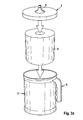
Figures 3a and3b , the process of loading asheet source 5 into the dispenser 1 is illustrated. In a first step shown inFig. 3a a sheet roll as the sheet source is put into theopen housing 2. Thesheet roll 5 is preferably a paper roll, in particular a center-feed roll, wherein theroll 5 is not provided with a central core, so that a free end in the center portion of theroll 5 is accessible. Thesheet roll 5 is positioned with its axis extending coaxially with the axis of thecylindrical housing 2. Thesheet roll 5 is dispensed from its center to its circumference. Thesheet roll 5 may be of any size to fit within thehousing 2 of the dispenser 1. - As shown in
Fig. 3b , to guide the free end through the dispensingopening 42 it can be fed firstly through thelid opening 33 before thelid 3 is attached onto thehousing 2. After thelid 3 is then attached to thehousing 2, the free end of thestrip 51 is then fed through the dispensingpiece 4 from thebase portion 41 to the dispensingopening 42. - To ensure that the
sheet roll 5 has minimum collapsing it might be useful to compress thesheet roll 5 along its cylindrical surface and to hold it such that its axial direction is substantially held in place. Hence,figures 4a to 4c show different structuring of thehousing 2 which allow fixing of thesheet roll 5 within thehousing 2. As shown inFigure 4a , thebottom portion 22 can be arranged outwardly concave, so that a center part of thebottom portion 22 is pressed onto one end of thecylindrical sheet roll 5 inside thehousing 2 thereby holding thesheet roll 5 between thebottom portion 22 and thelid 3. This supports the sheet product such that a collapsing of thesheet roll 5 is prevented. - As shown in the
housing 2 ofFigure 4b , recesses 26 and indentations can be provided in theside wall 21 of thehousing 2 that protrude inwardly and provide an inner diameter or cross-section of thehousing 2, respectively, that is equal to or less than the diameter of thesheet roll 5 to be inserted, so that thesheet roll 5 is compressed and thereby held securely within thehousing 2. -
Figure 4c shows acylindrical housing 2 having an angular e.g. hexagonal cross-section, so that side planes are formed which are configured to press against the outer circumference of thesheet roll 5 thereby holding thesheet roll 5 in place. - Since the dispenser 1 may be used in environments where moisture, dirt and debris are prevalent, a water resistant design is preferred for the dispenser 1 to exclude moisture and dirt from intruding into the interior of the dispenser 1. The
housing 2 is preferably made of plastic and can be manufactured by blow molding, injection molding and the like and may be formed with thehandle 6 as an integral product to increase the water tightness of the dispenser 1. Thelid 3 may be molded separately and may be made of the same or similar materials as thehousing 2. - As shown in
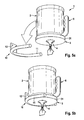
Figures 5a and 5b , awall holder 10 can be provided which can be attached to a wall and which provides abase part 12 and twosupport arms 11 which extend substantially perpendicular from thebase part 12 of thedispenser holder 10. Thecircumferential edge 31 of thelid 3 may have at least two opposite concave-shaped portions or has an encompassing concave-shaped groove. Thesupport arms 11 are configured such that the dispenser 1 can be attached by pushing thelid 3 between the two support arms 11 (Fig. 5a ). Thesupport arms 11 are biased against thelid 3 so that thesupport arms 11 are widened and thelid 3 is accommodated between thearms 11. Thearms 11 are then held within the concave groove around thecircumferential edge 31 of thelid 3 and prevent the dispenser 1 from falling out of thewall holder 10. - When the dispenser 1 is pushed onto the
wall holder 10 in a bottom-up position (Fig. 5b ), the dispensingpiece 4 protrudes downward from thelid 3, so that a wall-supported dispenser 1 can be obtained which allows for withdrawing sheets without the need to have the dispenser 1 grasped all the time. Thewall holder 10 allows removal and replacement of the dispenser 1 at will. - As shown in further embodiments of
Figures 6a and 6b , asupport hole 7 can be provided to hold e.g. aspray bottle 8 at the dispenser 1. Thespray bottle 8 usually has a spray bottle handle 81 which can be inserted into thesupport hole 7 so that by grasping the dispenser 1 thespray bottle 8 can also be carried without using an extra hand. Also thespray bottle 8 can be easily removed for use. Thesupport hole 7 can be either included in thehandle 6 wherein on the upper side of the short leg 61 a circular opening is formed in which the spray bottle handle 81 can be inserted. Alternatively, aring element 72 can be provided which protrudes sideways from thelid 3 e.g. by means of abeam 71 connecting thering element 72 and thelid 3. Thelid 3,beam 71 andring element 72 can be integrally formed.
Claims (12)
- Portable sheet product dispenser (1) for dispensing a strip of a sheet product, comprising:- a container for accommodating a source (5) of sheet product;- a dispensing piece (4) to be removably inserted into an opening (33) of the container in at least two different states, wherein in a one state the dispensing piece (4) protrudes outwardly from the container such that a dispensing opening (42) is elevated from an outer surface of the container, and wherein in another state the dispensing piece (4) protrudes inwardly into the container.
- Portable sheet product dispenser (1) according to claim 1, wherein the container includes a cylindrical housing (2) with a loading opening for loading a source (5) of sheet product and a closure element (3) for closing the loading opening of the housing (2), wherein the closure element (3) is attachable onto the housing (2) so that it can be removed for loading the source (5) of sheet product into the container.
- Portable sheet product dispenser (1) according to claim 2, wherein the opening (33) of the container is provided in the closure element (3).
- Portable sheet product dispenser (1) according to claims 2 and 3, wherein the cylindrical housing (2) has an open end which forms the opening (33), wherein the closure element (3) is configured to close the one end, wherein the closure element (3) has a planar outer surface (32) which is perpendicular to the axis of the cylindrical housing (2) when attached to the housing (2).
- Portable sheet product dispenser (1) according to one of the claims 1 to 4, wherein the dispensing piece (4) has a base portion (41) to be inserted into the opening (33) with two orientations so that the base portion (41) is held into the opening in form-fit or force-fit manner.
- Portable sheet product dispenser (1) according to one of the claims 1 to 5, wherein the dispenser (1) is loaded with a coreless centerfeed sheet roll (5) as the source of sheet product, wherein the housing (2) has means configured to hold the sheet roll (5) in a press-fit manner.
- Portable sheet product dispenser (1) according to claim 6, wherein the housing (2) has one of a concave bottom portion (22) at one end opposite to the loading opening, an indentation (26) of a side wall (21) of the housing (2) and an angular shape, in particular a hexagonal shape.
- Portable sheet product dispenser (1) according to one of the claims 1 to 7, wherein a handle (6) is attached at the container, wherein the handle (6) is L-shaped so that one leg (62) of the handle (6) is in parallel with a side wall of the cylindrical housing (2).
- Portable sheet product dispenser (1) according to one of the claims 1 to 8, wherein a support hole (7) is provided to allow insertion of a downwardly oriented handle of a spray bottle (8).
- Portable sheet product dispenser (1) according to claim 9, wherein the support hole (7) is formed outside a circumferential edge of the container.
- Arrangement comprising:- a wall holder (10) with a base part (12) for mounting at a wall and two arms (11) extending from the base part (12);- the portable sheet product dispenser (1) according to one of the claims 1 to 10, wherein the container has a circumferential edge (31) which has two opposite grooves,
wherein the arms (11) are configured to receive the circumferential edge (31) so that the arms engage the grooves and the portable sheet product dispenser (1) is supported by the wall holder (10). - Arrangement according to claim 11, wherein the arms (11) are biased so that they are pressed toward the circumferential edge (31) when the portable sheet product dispenser (1) is held between the arms (11).
Priority Applications (2)
| Application Number | Priority Date | Filing Date | Title |
|---|---|---|---|
| EP11008479.5A EP2583603A1 (en) | 2011-10-21 | 2011-10-21 | Portable sheet product dispenser |
| PCT/IB2012/002084 WO2013057565A2 (en) | 2011-10-21 | 2012-10-18 | Portable sheet product dispenser |
Applications Claiming Priority (1)
| Application Number | Priority Date | Filing Date | Title |
|---|---|---|---|
| EP11008479.5A EP2583603A1 (en) | 2011-10-21 | 2011-10-21 | Portable sheet product dispenser |
Publications (1)
| Publication Number | Publication Date |
|---|---|
| EP2583603A1 true EP2583603A1 (en) | 2013-04-24 |
Family
ID=47221489
Family Applications (1)
| Application Number | Title | Priority Date | Filing Date |
|---|---|---|---|
| EP11008479.5A Withdrawn EP2583603A1 (en) | 2011-10-21 | 2011-10-21 | Portable sheet product dispenser |
Country Status (2)
| Country | Link |
|---|---|
| EP (1) | EP2583603A1 (en) |
| WO (1) | WO2013057565A2 (en) |
Cited By (1)
| Publication number | Priority date | Publication date | Assignee | Title |
|---|---|---|---|---|
| US12096890B2 (en) | 2019-11-08 | 2024-09-24 | Essity Hygiene And Health Aktiebolag | Dispenser for a roll of absorbent paper web material |
Families Citing this family (3)
| Publication number | Priority date | Publication date | Assignee | Title |
|---|---|---|---|---|
| KR102497124B1 (en) | 2017-06-14 | 2023-02-08 | 킴벌리-클라크 월드와이드, 인크. | sheet product divider |
| USD915211S1 (en) | 2019-08-06 | 2021-04-06 | Kimberly-Clark Worldwide, Inc. | Cleaning product dispenser |
| US11812898B2 (en) | 2022-02-15 | 2023-11-14 | Dwayne Campbell | Portable towel dispensing device |
Citations (3)
| Publication number | Priority date | Publication date | Assignee | Title |
|---|---|---|---|---|
| US5346064A (en) * | 1993-02-25 | 1994-09-13 | James River Paper Company, Inc. | Center-pull roll product dispenser package |
| WO2006009859A1 (en) * | 2004-06-17 | 2006-01-26 | Sellars Absorbent Materials, Inc. | All weather absorbent towel dispenser |
| US20090302052A1 (en) * | 2008-06-04 | 2009-12-10 | Georgia-Pacific Consumer Products Lp | Container With Attachment Apparatus |
Family Cites Families (1)
| Publication number | Priority date | Publication date | Assignee | Title |
|---|---|---|---|---|
| GB2441323A (en) | 2006-08-29 | 2008-03-05 | Michael John Gordon | Wipes container with dispensing nozzle |
-
2011
- 2011-10-21 EP EP11008479.5A patent/EP2583603A1/en not_active Withdrawn
-
2012
- 2012-10-18 WO PCT/IB2012/002084 patent/WO2013057565A2/en not_active Ceased
Patent Citations (3)
| Publication number | Priority date | Publication date | Assignee | Title |
|---|---|---|---|---|
| US5346064A (en) * | 1993-02-25 | 1994-09-13 | James River Paper Company, Inc. | Center-pull roll product dispenser package |
| WO2006009859A1 (en) * | 2004-06-17 | 2006-01-26 | Sellars Absorbent Materials, Inc. | All weather absorbent towel dispenser |
| US20090302052A1 (en) * | 2008-06-04 | 2009-12-10 | Georgia-Pacific Consumer Products Lp | Container With Attachment Apparatus |
Cited By (1)
| Publication number | Priority date | Publication date | Assignee | Title |
|---|---|---|---|---|
| US12096890B2 (en) | 2019-11-08 | 2024-09-24 | Essity Hygiene And Health Aktiebolag | Dispenser for a roll of absorbent paper web material |
Also Published As
| Publication number | Publication date |
|---|---|
| WO2013057565A2 (en) | 2013-04-25 |
| WO2013057565A3 (en) | 2013-11-14 |
Similar Documents
| Publication | Publication Date | Title |
|---|---|---|
| EP2583602B1 (en) | Dispenser for static center-feed coreless roll of sheet product | |
| US7922036B2 (en) | Container for dispensing wipes | |
| US8282034B1 (en) | Multiple roll toilet paper holder and dispenser | |
| US20090194553A1 (en) | Wipes Canister | |
| US8631968B2 (en) | Tissue advancement device for tissue boxes | |
| US20090194555A1 (en) | Wipes Canister | |
| US20110315707A1 (en) | Dispenser for dispensing tissue paper | |
| US7533846B2 (en) | Towel roll product with supportive, protective wrapper | |
| US20100301136A1 (en) | Combined spray container and wipe dispensing device | |
| US7854346B2 (en) | Container for dispensing wipes | |
| EP2583603A1 (en) | Portable sheet product dispenser | |
| US20090200331A1 (en) | Inner container of sheets to be dispensed | |
| US9592976B2 (en) | System for singly dispensing fibrous filters from bulk | |
| KR101719905B1 (en) | A wastepaper holder | |
| US20170165999A1 (en) | Sheet material dispenser for utensil item | |
| US20120118908A1 (en) | System for singly dispensing fibrous filters from bulk | |
| EP2674084B1 (en) | Paper towel dispenser | |
| US20260054920A1 (en) | Wall-Mounted Pet Waste Bag Dispenser with Increased Storage Capacity and Efficient Core Removal System | |
| KR100741662B1 (en) | Roll case and roll paper with this case | |
| US9290342B1 (en) | System for singly dispensing fibrous filters from bulk | |
| JP7479309B2 (en) | Sanitary tissue storage container | |
| US20060004411A1 (en) | Package containing a first housing for storing unused disposable cleaning products and a second housing for storing used cleaning products | |
| KR100853567B1 (en) | Tissue Bin | |
| JP2022026382A (en) | Sanitary tissue paper storage container | |
| US20070125793A1 (en) | Sanitary paper dispenser |
Legal Events
| Date | Code | Title | Description |
|---|---|---|---|
| PUAI | Public reference made under article 153(3) epc to a published international application that has entered the european phase |
Free format text: ORIGINAL CODE: 0009012 |
|
| AK | Designated contracting states |
Kind code of ref document: A1 Designated state(s): AL AT BE BG CH CY CZ DE DK EE ES FI FR GB GR HR HU IE IS IT LI LT LU LV MC MK MT NL NO PL PT RO RS SE SI SK SM TR |
|
| AX | Request for extension of the european patent |
Extension state: BA ME |
|
| 17P | Request for examination filed |
Effective date: 20131024 |
|
| RAX | Requested extension states of the european patent have changed |
Extension state: BA Payment date: 20131024 Extension state: ME Payment date: 20131024 |
|
| RBV | Designated contracting states (corrected) |
Designated state(s): AL AT BE BG CH CY CZ DE DK EE ES FI FR GB GR HR HU IE IS IT LI LT LU LV MC MK MT NL NO PL PT RO RS SE SI SK SM TR |
|
| STAA | Information on the status of an ep patent application or granted ep patent |
Free format text: STATUS: THE APPLICATION HAS BEEN WITHDRAWN |
|
| 18W | Application withdrawn |
Effective date: 20140901 |