EP2582586B1 - Box with lid and handle - Google Patents
Box with lid and handle Download PDFInfo
- Publication number
- EP2582586B1 EP2582586B1 EP11743422.5A EP11743422A EP2582586B1 EP 2582586 B1 EP2582586 B1 EP 2582586B1 EP 11743422 A EP11743422 A EP 11743422A EP 2582586 B1 EP2582586 B1 EP 2582586B1
- Authority
- EP
- European Patent Office
- Prior art keywords
- box
- lid
- vertical
- horizontal
- storage device
- Prior art date
- Legal status (The legal status is an assumption and is not a legal conclusion. Google has not performed a legal analysis and makes no representation as to the accuracy of the status listed.)
- Active
Links
Images




Classifications
-
- B—PERFORMING OPERATIONS; TRANSPORTING
- B65—CONVEYING; PACKING; STORING; HANDLING THIN OR FILAMENTARY MATERIAL
- B65D—CONTAINERS FOR STORAGE OR TRANSPORT OF ARTICLES OR MATERIALS, e.g. BAGS, BARRELS, BOTTLES, BOXES, CANS, CARTONS, CRATES, DRUMS, JARS, TANKS, HOPPERS, FORWARDING CONTAINERS; ACCESSORIES, CLOSURES, OR FITTINGS THEREFOR; PACKAGING ELEMENTS; PACKAGES
- B65D43/00—Lids or covers for rigid or semi-rigid containers
- B65D43/26—Mechanisms for opening or closing, e.g. pedal-operated
-
- A—HUMAN NECESSITIES
- A45—HAND OR TRAVELLING ARTICLES
- A45C—PURSES; LUGGAGE; HAND CARRIED BAGS
- A45C13/00—Details; Accessories
- A45C13/26—Special adaptations of handles
- A45C13/28—Combinations of handles with other devices
-
- B—PERFORMING OPERATIONS; TRANSPORTING
- B25—HAND TOOLS; PORTABLE POWER-DRIVEN TOOLS; MANIPULATORS
- B25H—WORKSHOP EQUIPMENT, e.g. FOR MARKING-OUT WORK; STORAGE MEANS FOR WORKSHOPS
- B25H3/00—Storage means or arrangements for workshops facilitating access to, or handling of, work tools or instruments
- B25H3/02—Boxes
-
- B—PERFORMING OPERATIONS; TRANSPORTING
- B65—CONVEYING; PACKING; STORING; HANDLING THIN OR FILAMENTARY MATERIAL
- B65D—CONTAINERS FOR STORAGE OR TRANSPORT OF ARTICLES OR MATERIALS, e.g. BAGS, BARRELS, BOTTLES, BOXES, CANS, CARTONS, CRATES, DRUMS, JARS, TANKS, HOPPERS, FORWARDING CONTAINERS; ACCESSORIES, CLOSURES, OR FITTINGS THEREFOR; PACKAGING ELEMENTS; PACKAGES
- B65D25/00—Details of other kinds or types of rigid or semi-rigid containers
- B65D25/28—Handles
- B65D25/2802—Handles fixed, i.e. non-swingable, handles
- B65D25/2826—Handles fixed, i.e. non-swingable, handles provided on a local area of the upper (top) wall, e.g. U-shaped
Definitions
- EP 1520 660 B1 discloses a storage device comprising a box having a lid and a handle.
- a handle In order to lock the lid to the box, a handle is adapted to operate a locking mechanism, such that when the handle is swung from a vertical orientation to a horizontal orientation, then the locking mechanism will release the lid form the box.
- the locking mechanism itself consists of a locking element that is adapted to be fixed in two recesses in the handle, depending how the orientation of the handle is provided. In other words a somewhat complex locking mechanism as far manufacturing costs of the device is involved.
- the orientation of the handle is parallel with the box, which is not the most suitable direction in relation to the direction of a users hand, when the user transport the storage device.
- a storage device of the type defined in the preamble of Claim 1 is described in DE 2322358 .
- This known box has a somewhat complicated locking means involving springs, balls etc.
- the object of the invention is achieved in a storage device which is provided with the characterizing features of claim 1.
- the horizontal part is terminated by an oblique - angled taper.
- the lid is coupled to the box by at least two L-formed top profiles on the top of the box, said profiles being coupled to a corresponding plurality of downward pointing L formed profiles in the bottom of the lid, and where the taper is arranged to be seated in a channel provided between the L-formed profiles, thereby locking the profiles to each other and the lid to the box, a very robust coupling of the lid to the box as a secure locking of the L- formed profiles during transportation of the storage device is achieved.
- the handle has an extended vertical part that passes through a hole in the lid, said extended part is terminated by an elastic taper, having bigger dimensions than the hole in the lid.
- the horizontal part is vertically moveable in a slot and a depression as well, said slot and said depression are provided in a wall of the box, said depression is narrower than the slot.
- a storage device according to the invention is designated with the number 1.
- the storage device consists of a box 2, having a lid 3, that can be fixed to the box 2 by a hinge or can be loosely or otherwise placed on the top of the box as explained later.
- a handle 4 is located on the lid 3, said handle is adapted to lock or unlock the lid from the box 2.
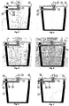
- Fig. 2 and fig 3 shows the box 2 having its lid 3 connected to the box 2 by a hinge 6.
- the handle 4 is equipped with a vertical extension part 7, that passes through the lid 3. This vertical part is equipped with a horizontal part 8.
- the handle can be moved in a horizontal direction fx. 20° in relation to the lengthwise direction of the box 2.
- the fig. 4 version differs from fig. 2 in that the lid 3 is equipped with a hole 12 in a vertical extension part 5 that is adapted to let the horizontal extended part 8 pass through the hole 12, and then contribute to a stronger lock of the lid 3 to the box 2.
- the fig. 5 version differs from fig. 4 in, that a further hole 10a is provided in the box 2 near the hinge 6, and again giving a stronger lock of the lid 3 to the box 2.
- the version in fig. 6 differs from the version in fig. 4 in that the extended vertical part 5 is placed outside the box 2, whereas the fig. 7 version shows combinations on the versions in fig. 4 -6 .
- the fig 8 version has in stead of a hinge a horizontal extended prolonged part 8b that is led through a hole 10b in the box 2.
- the fig. 9 version corresponds to the fig 8 . version but has its extended parts led through holes 12a, 12b in vertical parts of the lid.
- a not illustrated version corresponds to that of the fig. 7 version, but differs in that the extended vertical part 8d passes through two further holes in the box 2 and four extended vertical parts in the lid 3.
- Another not illustrated version corresponds to the aforementioned, also not illustrated version where the extended horizontal part is prolonged and led through two holes in the box 2 but only two holes 12, 12b in the vertical extended part 8c on the lids.
- the versions of fig. 12 - 14 have replaced the holes in the box 2 by at least one edge 14, that is adapted to retake up the extended horizontal part 8 of the handle 4.
- the fig. 15 and 16 versions correspond to the fig. 12 - 14 , but without hinges.
- the versions in fig 17 and 18 differ from the foregoing versions in that the handle 4 at its underside is equipped with an elastic taper 15, adapted to penetrate in a hole 16 in the lid 4.
- the extended vertical part 7 of the handle 4 is terminated by the horizontal part 8, that is moveable in a longer slot 10 and a narrower depression 24, both of which are provided in the wall of the box.
- the handle downwards his force will apply a movement to the handle downwards and enable the user to swing the handle in a horizontal movement, that offers him the possibility to lock and unlock the handle, so that the lid will be unlocked from or locked to the box, in the same way as already explained earlier.
- the lid can afterwards be released from the box 2, when the user presses the handle downwards and free the horizontal bar 8 from the depression 24. He can then swing the handle in an opposite horizontal direction in order to release the horizontal part 8 from the slot 10 and lift the lid from the box.
- the lengthwise direction of the storage device will not seek to be affected through the users hand forces. In normal position of a users hand it is directed about 20° in relation to direction of his view.
- the four last figures 24 - 27 demonstrate a storage box where the lid is releasable couple to the box by using special profiling between the lid and the box.
- Figure 24 designates couplings means in form of a top formed L-profile 27 in a lid that is adapted to be coupled to means 30 that are arranged to form a hole or a passage 23 that is adapted to accommodate a taper 19.
- This taper 19 terminates, cf. fig. 27 , in such a way, that when the taper is placed as shown in fig. 24 and 27 , then the lid will be locked or unlocked to the not shown box.
- the handle is moveable in horizontal direction in order to lock or unlock the lid to the box, incorporating all the advantages as ergonomic lift and so on.
Landscapes
- Engineering & Computer Science (AREA)
- Mechanical Engineering (AREA)
- Closures For Containers (AREA)
Description
- The invention relates to a storage device in accordance with the preamble of claim 1.
EP 1520 660 B1 discloses a storage device comprising a box having a lid and a handle. - In order to lock the lid to the box, a handle is adapted to operate a locking mechanism, such that when the handle is swung from a vertical orientation to a horizontal orientation, then the locking mechanism will release the lid form the box.
- When the handle is swung from the horizontal orientation to the vertical orientation, then the lid will be locked from the box.
- The locking mechanism itself consists of a locking element that is adapted to be fixed in two recesses in the handle, depending how the orientation of the handle is provided. In other words a somewhat complex locking mechanism as far manufacturing costs of the device is involved.
- It is also noted, that when the known box is carried, the orientation of the handle is parallel with the box, which is not the most suitable direction in relation to the direction of a users hand, when the user transport the storage device.
- A further example of known storage devices having a lid not hinged to the box can be seen in to
WO 2009/149965 A1 . - A storage device of the type defined in the preamble of Claim 1 is described in
DE 2322358 . - This known box has a somewhat complicated locking means involving springs, balls etc.
- On this background it is an object of the invention to reach to a storage device that is simpler constructed than the known devices. Moreover it should also be more ergonomically designed, in the sense that a user obtains a more comfortable feeling, when carrying and transporting the storage device.
- The object of the invention is achieved in a storage device which is provided with the characterizing features of claim 1.
- In this way a simple storage box build up of few components is achieved as well as a very ergonomic design is incorporated. It is an advantage if, as stated in
Claim 2, the 20° displacement of the handle in relation to the direction of the lengthwise direction of the box, depends on whether a left hand- or a right hand user uses it. - To implement the storage device with few components, it is advantageous if as stated in
claim 3, the horizontal part is terminated by an oblique - angled taper. - More expedient embodiments of the invention are outlined in claim 4 -7. It is possible that the lid is coupled to the box by at least two L-formed top profiles on the top of the box, said profiles being coupled to a corresponding plurality of downward pointing L formed profiles in the bottom of the lid, and where the taper is arranged to be seated in a channel provided between the L-formed profiles, thereby locking the profiles to each other and the lid to the box, a very robust coupling of the lid to the box as a secure locking of the L- formed profiles during transportation of the storage device is achieved.
- For an easier manufacturing of the components, that define the storage device, it is an advantage, if as stated in
Claim 8, that the handle has an extended vertical part that passes through a hole in the lid, said extended part is terminated by an elastic taper, having bigger dimensions than the hole in the lid. - To secure the lid properly to the storing device box during transport it is expedient, if the horizontal part is vertically moveable in a slot and a depression as well, said slot and said depression are provided in a wall of the box, said depression is narrower than the slot.
- The invention will now be more fully explained in connection with the drawings, in which
-
Fig. 1 shows a basic storage device according to the invention, -
Fig. 2 - 7 shows in cross sectional different embodiments of storage devices having lids hinged to the storage device, -
Fig. 8 and 9 shows in cross sectional different embodiments of storage devices having lids not hinged to the storage device, - Figs. 10 and 11 (omitted)
-
Fig. 12 - 14 andfig. 18 , shows in cross sectional different embodiments of alternative versions of these offig. 2-7 , -
Fig. 15 - 17 shows different alternatives in cross sectional embodiments of storage devices having lids not hinged to the storage device, -
Fig 19 - fig 20 shows in cross sectional a storage device having an incorporated lock that locks the lid to the storage device during transport of the storage device, -
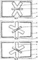
Fig 21 - 23 shows from above a storage device with a handle adapted, when a user wish to shift between right and left hand. -
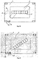
Fig. 24, 25 shows schematic in cross sectional an embodiment of a storage device in which the lid of the storage device is coupled to the box by profiles, whereas -
Fig. 26- 27 shows from above how the lid is locked to the storage device infig. 24 and fig. 25 by use of the principles according to the invention. - As seen from
fig. 1 a storage device according to the invention is designated with the number 1. - The storage device consists of a
box 2, having alid 3, that can be fixed to thebox 2 by a hinge or can be loosely or otherwise placed on the top of the box as explained later. - Further a
handle 4 is located on thelid 3, said handle is adapted to lock or unlock the lid from thebox 2. -
Fig. 2 and fig 3 . shows thebox 2 having itslid 3 connected to thebox 2 by a hinge 6. - The
handle 4 is equipped with avertical extension part 7, that passes through thelid 3. This vertical part is equipped with ahorizontal part 8. - The handle can be moved in a horizontal direction fx. 20° in relation to the lengthwise direction of the
box 2. - In this way it is possible to lock or unlock the lid from the box, since when the handle is arranged in the lengthwise direction of the box, it will have no connection to the box, whereas when it takes the position in
fig. 3 it will pass through ahole 10 in thebox 2 and then lock the lid to thebox 2. - In other words it is very simply to lock and unlock the lid from the box by a simple movement of the handle in a horizontal direction, and as it will be further explained later, a very ergonomic effect for a user is obtained.
- The
fig. 4 version differs fromfig. 2 in that thelid 3 is equipped with a hole 12 in a vertical extension part 5 that is adapted to let the horizontal extendedpart 8 pass through the hole 12, and then contribute to a stronger lock of thelid 3 to thebox 2. - The
fig. 5 version differs fromfig. 4 in, that a further hole 10a is provided in thebox 2 near the hinge 6, and again giving a stronger lock of thelid 3 to thebox 2. The version infig. 6 differs from the version infig. 4 in that the extended vertical part 5 is placed outside thebox 2, whereas thefig. 7 version shows combinations on the versions infig. 4 -6 . - Now coming to the versions shown in
fig. 8 and 9 , they differ basically in that the hinge 6 infig 2 - 7 is omitted. - The
fig 8 version has in stead of a hinge a horizontal extended prolonged part 8b that is led through a hole 10b in thebox 2. - The
fig. 9 version corresponds to thefig 8 . version but has its extended parts led through holes 12a, 12b in vertical parts of the lid. - A not illustrated version corresponds to that of the
fig. 7 version, but differs in that the extended vertical part 8d passes through two further holes in thebox 2 and four extended vertical parts in thelid 3. - Another not illustrated version corresponds to the aforementioned, also not illustrated version where the extended horizontal part is prolonged and led through two holes in the
box 2 but only two holes 12, 12b in the vertical extended part 8c on the lids. - The versions of
fig. 12 - 14 have replaced the holes in thebox 2 by at least oneedge 14, that is adapted to retake up the extendedhorizontal part 8 of thehandle 4. Thefig. 15 and 16 versions correspond to thefig. 12 - 14 , but without hinges. - The versions in
fig 17 and 18 differ from the foregoing versions in that thehandle 4 at its underside is equipped with anelastic taper 15, adapted to penetrate in ahole 16 in thelid 4. - In this way it is easy to manufacture the handle as a sole component that is easy to mount and being not replaceable in the slot in the
hole 16 due to the elastic properties of thetaper 15. In order to secure the lid properly to the storage box, especially during transport, a modifiedslot 10 with an extra depression in the box is presented infig. 19 and fig. 20 . - According to
fig. 19 and fig. 20 , it is seen that the extendedvertical part 7 of thehandle 4 is terminated by thehorizontal part 8, that is moveable in alonger slot 10 and anarrower depression 24, both of which are provided in the wall of the box. When a user presses the handle downwards, his force will apply a movement to the handle downwards and enable the user to swing the handle in a horizontal movement, that offers him the possibility to lock and unlock the handle, so that the lid will be unlocked from or locked to the box, in the same way as already explained earlier. The lid can afterwards be released from thebox 2, when the user presses the handle downwards and free thehorizontal bar 8 from thedepression 24. He can then swing the handle in an opposite horizontal direction in order to release thehorizontal part 8 from theslot 10 and lift the lid from the box. - In order to adapt the invention to all users, i.e. right or left handed users attention is drawn to
fig. 21 to fig 23 . - In these figures the
box 2 withhandle 4 and the lid is seen from above. - In
fig. 21 it is seen that the direction of thehandle 4, has the same direction as the length of the box itself. - In
fig. 22 the handle is moved left about 20° relative to the length of the box direction resulting in that the horizontally extendedpart 8 accesses the holes in the box or the lid as earlier explained. - In
fig 23 is seen that thehandle 4 is again moved 20° relative to the length of the box but now to the right in relation to the length of the box. In both situations it is noted that when a user transport the storage device the handle will fit to the orientation of the users hand. - In other words the lengthwise direction of the storage device will not seek to be affected through the users hand forces. In normal position of a users hand it is directed about 20° in relation to direction of his view.
- From above it can be concluded, that a very ergonomic design of a storage box having a lot of other advantages is the result of the invention.
- The four last
figures 24 - 27 demonstrate a storage box where the lid is releasable couple to the box by using special profiling between the lid and the box. - The basic idea of the details how the lid is coupled to the box can be found in the above mentioned
WO 2009/140965 A1 . - For these reasons only the necessary parts of the coupling in order to understand the use of the invention are explained here.
Figure 24 designates couplings means in form of a top formed L-profile 27 in a lid that is adapted to be coupled to means 30 that are arranged to form a hole or apassage 23 that is adapted to accommodate ataper 19. Thistaper 19 terminates, cf.fig. 27 , in such a way, that when the taper is placed as shown infig. 24 and27 , then the lid will be locked or unlocked to the not shown box. - As already explained the handle is moveable in horizontal direction in order to lock or unlock the lid to the box, incorporating all the advantages as ergonomic lift and so on.
- Even though the invention is explained in relation to especially tool boxes it is noted, that within the scope of the claims, the invention can be used in connection with a lot of other boxes, such as handbags, beauty boxes, coffers and the like.
Claims (8)
- A storage device (1) comprising a box (2) provided with a lid (3) and a handle (4), wherein the lid (3) is placed on the box (2) in a vertical direction of the box (2), where the storage device (1) has locking means adapted to lock the lid to the box, and where the locking means consist of a male part and a counter part, such as a female part or an edge (14), wherein in the locked state of the lid (3) and the box (2) the male part is engaged with the counter part and wherein in the unlocked state of the lid (3) and the box (2) the male part is disengaged from the counter part, said male part constitutes a part of the handle (4), whereas the counter part is provided in the box (2) or in the box and the lid, wherein the box (2) has a rectangular horizontal outline defining a longitudinal axis of the box and wherein the handle (4) has an oblong shape with a longitudinal axis that when the lid is unlocked to the box is coincident with the longitudinal axis of the box, and wherein the handle (4) is operated by a horizontal swivelling such that when the lid (3) is locked to the box then the longitudinal axis of the handle is approximately 20° displaced in relation to the longitudinal axis of the box, characterized in, that the male part has a vertical part (7) extending in the vertical direction of the box (2) and passing through a hole in the lid (3), and in that the vertical part (7) is terminated by a horizontal part (8) forming the counter part engaging part, in a horizontal direction which is perpendicular to the vertical direction of the box (2).
- A storage device according to claim 1, characterized in, that the handle (4) can be moved in relation to the longitudinal axis of the box either to the left or to the right by said approximate 20° displacement, respectively, depending on whether a left hand user or a right hand user uses it.
- Storage device according to claim 1 or 2, characterized in, that the horizontal part (8) is provided with an oblique-angled taper (19) at its underside which extends in the vertical direction of the box (2) wherein such taper (19) penetrates into a hole (16) provided in the lid (3).
- A storage device according to claim 1 - 3, characterized in, that the lid (3) is hinged to the box, and in that the female part consists of a hole (10) in a vertical side wall of the box and a hole (12) in a vertical extension part (5) of the lid (3) vertically overlapping said vertical side wall of the box, or the female part consist of two holes (12, 12a) in two vertical extension parts of the lid and one hole (10) in a vertical side wall of the box extending between the two extension parts, wherein in the locked state of the lid (3) the horizontal part (8) penetrates into each of the associated holes.
- A storage device according to claims 1 - 3, characterized in, that the lid (3) is hinged to the box and that the counter part consists of an edge (14) in the box defined by a horizontal protrusion of a vertical side wall of the box beneath which the horizontal part projects in the locked state of the lid (3).
- A storage device according to claims 1 - 3, characterized in, that the lid (3) is hinged to the box and that the counter part consists of an edge (14) or of two edges (14) in the box each defined by a horizontal protrusion of a vertical side wall of the box and of a hole in a vertical extension part (5) of the lid (3) vertically overlapping said vertical side wall of the box, wherein the horizontal part protrudes through the hole and in the locked state of the lid (3) projects beneath each associated edge.
- A storage device according to claim 1- 3, characterized in, that the lid (3) is locked to the box by the male part having the vertical part (7) passing through a vertical hole in the lid (3), said vertical part (7) has two opposite horizontal parts, and in that the counter parts either consist of two edges (14,14a) in the box each of them defined by a horizontal protrusion of a vertical side wall of the box or that the counter parts consist of two holes each provided in a vertical extension part (5) of the lid (3) and of two edges in the box (14,14a) each of them defined by a horizontal protrusion of a vertical side wall of the box, wherein each of the opposite horizontal parts in the locked state of the lid (3) is projecting beneath an associated one of the two edges.
- A storage device according to claim 1 - 7, characterized in, that the handle has an extended vertical part (16) that passes through a hole in the lid, said extended part is terminated by an elastic taper (15) having bigger dimensions than the hole in the lid.
Applications Claiming Priority (3)
| Application Number | Priority Date | Filing Date | Title |
|---|---|---|---|
| DKPA201000518 | 2010-06-12 | ||
| DKPA201000597A DK201000597A (en) | 2010-07-06 | 2010-07-06 | Storage device consisting of three parts |
| PCT/DK2011/000061 WO2012000497A1 (en) | 2010-06-12 | 2011-06-14 | Box with lid and handle |
Publications (2)
| Publication Number | Publication Date |
|---|---|
| EP2582586A1 EP2582586A1 (en) | 2013-04-24 |
| EP2582586B1 true EP2582586B1 (en) | 2017-05-17 |
Family
ID=44508541
Family Applications (1)
| Application Number | Title | Priority Date | Filing Date |
|---|---|---|---|
| EP11743422.5A Active EP2582586B1 (en) | 2010-06-12 | 2011-06-14 | Box with lid and handle |
Country Status (3)
| Country | Link |
|---|---|
| EP (1) | EP2582586B1 (en) |
| ES (1) | ES2632569T3 (en) |
| WO (1) | WO2012000497A1 (en) |
Families Citing this family (32)
| Publication number | Priority date | Publication date | Assignee | Title |
|---|---|---|---|---|
| US11267119B2 (en) | 2015-12-14 | 2022-03-08 | Milwaukee Electric Tool Corporation | Storage device system |
| CN110893610A (en) | 2016-05-02 | 2020-03-20 | 凯特尔塑料有限公司 | Utility module and coupling mechanism |
| WO2018213560A1 (en) | 2017-05-17 | 2018-11-22 | Milwaukee Electric Tool Corporation | Storage device system |
| CN107117365B (en) * | 2017-05-31 | 2022-11-29 | 苏州市职业大学 | Three-point opening pharmaceutical packaging box with childproof function |
| USD872478S1 (en) | 2017-06-12 | 2020-01-14 | Yeti Coolers, Llc | Container |
| USD838983S1 (en) | 2017-06-12 | 2019-01-29 | Yeti Coolers, Llc | Container |
| USD872485S1 (en) | 2017-06-12 | 2020-01-14 | Yeti Coolers, Llc | Container |
| USD869160S1 (en) | 2017-06-12 | 2019-12-10 | Yeti Coolers, Llc | Container |
| US11976498B2 (en) | 2017-06-12 | 2024-05-07 | Yeti Coolers, Llc | Container and latching system |
| US11685573B2 (en) | 2017-06-12 | 2023-06-27 | Yeti Coolers, Llc | Carry strap for container |
| CA178734S (en) | 2017-06-12 | 2019-05-31 | Yeti Coolers Llc | Container |
| USD838984S1 (en) | 2017-06-12 | 2019-01-29 | Yeti Coolers, Llc | Container |
| USD828029S1 (en) | 2017-06-12 | 2018-09-11 | Yeti Coolers, Llc | Container |
| EP3638598B1 (en) | 2017-06-12 | 2023-01-18 | Yeti Coolers, LLC | Container and latching system |
| USD873020S1 (en) | 2017-06-12 | 2020-01-21 | Yeti Coolers, Llc | Container |
| USD828028S1 (en) | 2017-06-12 | 2018-09-11 | Yeti Coolers, Llc | Container |
| USD840150S1 (en) | 2017-06-12 | 2019-02-12 | Yeti Coolers, Llc | Container |
| US12108853B2 (en) | 2019-01-06 | 2024-10-08 | Yeti Coolers, Llc | Luggage system |
| WO2019028041A1 (en) | 2017-07-31 | 2019-02-07 | Milwaukee Electric Tool Corporation | STORAGE DEVICE SYSTEM |
| WO2019147801A2 (en) | 2018-01-24 | 2019-08-01 | Milwaukee Electric Tool Corporation | Tool storage |
| USD907445S1 (en) | 2018-12-11 | 2021-01-12 | Yeti Coolers, Llc | Container accessories |
| USD904829S1 (en) | 2018-12-11 | 2020-12-15 | Yeti Coolers, Llc | Container accessories |
| US12225993B2 (en) | 2019-01-06 | 2025-02-18 | Yeti Coolers, Llc | Luggage system |
| CN113271806A (en) | 2019-01-06 | 2021-08-17 | 野醍冷却器有限责任公司 | Luggage system |
| IL269564B2 (en) | 2019-09-23 | 2023-11-01 | Keter Home & Garden Products Ltd | Work donkey |
| USD951643S1 (en) | 2020-06-30 | 2022-05-17 | Yeti Coolers, Llc | Luggage |
| USD961926S1 (en) | 2020-06-30 | 2022-08-30 | Yeti Coolers, Llc | Luggage |
| USD954436S1 (en) | 2020-06-30 | 2022-06-14 | Yeti Coolers, Llc | Luggage |
| USD963344S1 (en) | 2020-06-30 | 2022-09-13 | Yeti Coolers, Llc | Luggage |
| USD994438S1 (en) | 2020-12-16 | 2023-08-08 | Yeti Coolers, Llc | Container |
| USD985937S1 (en) | 2020-12-16 | 2023-05-16 | Yeti Coolers, Llc | Container |
| USD960648S1 (en) | 2020-12-16 | 2022-08-16 | Yeti Coolers, Llc | Container accessory |
Family Cites Families (6)
| Publication number | Priority date | Publication date | Assignee | Title |
|---|---|---|---|---|
| US2437099A (en) * | 1945-07-25 | 1948-03-02 | Krupp Louis | Combination handle and closure means for handbags |
| DE2322358A1 (en) * | 1973-05-03 | 1974-11-14 | Uwe Dr Med Dr Phil Stocksmeier | DEVICE FOR CARRYING A LOAD |
| ES1027080Y (en) * | 1994-02-17 | 1995-01-16 | Ind Tayg S L | NEW TOOL BOX. |
| US7246718B2 (en) * | 2003-10-02 | 2007-07-24 | Zag Industries Ltd. | Toolbox with handle having cover locking mechanism |
| WO2009140965A1 (en) | 2008-05-19 | 2009-11-26 | J.O. Madsen Aps | Storage arrangement consisting of two parts such as two cases or one case and one lid |
| DE102008025489A1 (en) | 2008-05-28 | 2009-12-24 | Siemens Aktiengesellschaft | Method and system for monitoring a safety-related system |
-
2011
- 2011-06-14 ES ES11743422.5T patent/ES2632569T3/en active Active
- 2011-06-14 WO PCT/DK2011/000061 patent/WO2012000497A1/en not_active Ceased
- 2011-06-14 EP EP11743422.5A patent/EP2582586B1/en active Active
Also Published As
| Publication number | Publication date |
|---|---|
| WO2012000497A1 (en) | 2012-01-05 |
| EP2582586A1 (en) | 2013-04-24 |
| ES2632569T3 (en) | 2017-09-14 |
Similar Documents
| Publication | Publication Date | Title |
|---|---|---|
| WO2012000497A1 (en) | Box with lid and handle | |
| EP1848873B1 (en) | Snap-type locking device | |
| US9393684B2 (en) | Toolbox | |
| CA2694801C (en) | Integrated storage system with locking containers | |
| EP2474393B1 (en) | Container with latch | |
| USD534448S1 (en) | Authentication device | |
| US9131770B2 (en) | Containers | |
| EP2436492B1 (en) | Container assembly | |
| JP5836877B2 (en) | Tool storage case | |
| USD589779S1 (en) | Ergonomic locking pin | |
| CN101115412B (en) | Box | |
| CN109414810A (en) | stackable system container | |
| US20150320207A1 (en) | Bookcase | |
| US11414878B2 (en) | Unlocking structure of workbench ladder | |
| JP2010137920A (en) | Lock box having lid of slide type | |
| CN104960813A (en) | Container | |
| CA2793820A1 (en) | Toolbox assembly | |
| US10004350B1 (en) | Knife holder | |
| WO2005102852A1 (en) | A locking system provided with a handle to be used in a container | |
| USD602340S1 (en) | Modular panel key lock | |
| KR20180038172A (en) | Lock for a folding door | |
| US20070130731A1 (en) | Case handle for protective cases | |
| US20060181182A1 (en) | Cabinet drawer drivingly connected locking mechanism | |
| EP1647492A1 (en) | Foldable crate | |
| CN204751106U (en) | Container |
Legal Events
| Date | Code | Title | Description |
|---|---|---|---|
| PUAI | Public reference made under article 153(3) epc to a published international application that has entered the european phase |
Free format text: ORIGINAL CODE: 0009012 |
|
| 17P | Request for examination filed |
Effective date: 20130115 |
|
| AK | Designated contracting states |
Kind code of ref document: A1 Designated state(s): AL AT BE BG CH CY CZ DE DK EE ES FI FR GB GR HR HU IE IS IT LI LT LU LV MC MK MT NL NO PL PT RO RS SE SI SK SM TR |
|
| DAX | Request for extension of the european patent (deleted) | ||
| RAP1 | Party data changed (applicant data changed or rights of an application transferred) |
Owner name: TTS TOOLTECHNIC SYSTEMS AG & CO. KG |
|
| 17Q | First examination report despatched |
Effective date: 20140430 |
|
| GRAP | Despatch of communication of intention to grant a patent |
Free format text: ORIGINAL CODE: EPIDOSNIGR1 |
|
| INTG | Intention to grant announced |
Effective date: 20161222 |
|
| GRAS | Grant fee paid |
Free format text: ORIGINAL CODE: EPIDOSNIGR3 |
|
| GRAA | (expected) grant |
Free format text: ORIGINAL CODE: 0009210 |
|
| AK | Designated contracting states |
Kind code of ref document: B1 Designated state(s): AL AT BE BG CH CY CZ DE DK EE ES FI FR GB GR HR HU IE IS IT LI LT LU LV MC MK MT NL NO PL PT RO RS SE SI SK SM TR |
|
| REG | Reference to a national code |
Ref country code: GB Ref legal event code: FG4D |
|
| REG | Reference to a national code |
Ref country code: CH Ref legal event code: EP |
|
| REG | Reference to a national code |
Ref country code: IE Ref legal event code: FG4D |
|
| REG | Reference to a national code |
Ref country code: CH Ref legal event code: NV Representative=s name: TROESCH SCHEIDEGGER WERNER AG, CH Ref country code: AT Ref legal event code: REF Ref document number: 894218 Country of ref document: AT Kind code of ref document: T Effective date: 20170615 |
|
| REG | Reference to a national code |
Ref country code: DE Ref legal event code: R096 Ref document number: 602011038043 Country of ref document: DE Ref country code: FR Ref legal event code: PLFP Year of fee payment: 7 |
|
| REG | Reference to a national code |
Ref country code: SE Ref legal event code: TRGR |
|
| REG | Reference to a national code |
Ref country code: NL Ref legal event code: FP |
|
| REG | Reference to a national code |
Ref country code: ES Ref legal event code: FG2A Ref document number: 2632569 Country of ref document: ES Kind code of ref document: T3 Effective date: 20170914 |
|
| REG | Reference to a national code |
Ref country code: LT Ref legal event code: MG4D |
|
| PG25 | Lapsed in a contracting state [announced via postgrant information from national office to epo] |
Ref country code: LT Free format text: LAPSE BECAUSE OF FAILURE TO SUBMIT A TRANSLATION OF THE DESCRIPTION OR TO PAY THE FEE WITHIN THE PRESCRIBED TIME-LIMIT Effective date: 20170517 Ref country code: HR Free format text: LAPSE BECAUSE OF FAILURE TO SUBMIT A TRANSLATION OF THE DESCRIPTION OR TO PAY THE FEE WITHIN THE PRESCRIBED TIME-LIMIT Effective date: 20170517 Ref country code: GR Free format text: LAPSE BECAUSE OF FAILURE TO SUBMIT A TRANSLATION OF THE DESCRIPTION OR TO PAY THE FEE WITHIN THE PRESCRIBED TIME-LIMIT Effective date: 20170818 Ref country code: NO Free format text: LAPSE BECAUSE OF FAILURE TO SUBMIT A TRANSLATION OF THE DESCRIPTION OR TO PAY THE FEE WITHIN THE PRESCRIBED TIME-LIMIT Effective date: 20170817 Ref country code: FI Free format text: LAPSE BECAUSE OF FAILURE TO SUBMIT A TRANSLATION OF THE DESCRIPTION OR TO PAY THE FEE WITHIN THE PRESCRIBED TIME-LIMIT Effective date: 20170517 |
|
| PG25 | Lapsed in a contracting state [announced via postgrant information from national office to epo] |
Ref country code: LV Free format text: LAPSE BECAUSE OF FAILURE TO SUBMIT A TRANSLATION OF THE DESCRIPTION OR TO PAY THE FEE WITHIN THE PRESCRIBED TIME-LIMIT Effective date: 20170517 Ref country code: PL Free format text: LAPSE BECAUSE OF FAILURE TO SUBMIT A TRANSLATION OF THE DESCRIPTION OR TO PAY THE FEE WITHIN THE PRESCRIBED TIME-LIMIT Effective date: 20170517 Ref country code: RS Free format text: LAPSE BECAUSE OF FAILURE TO SUBMIT A TRANSLATION OF THE DESCRIPTION OR TO PAY THE FEE WITHIN THE PRESCRIBED TIME-LIMIT Effective date: 20170517 Ref country code: BG Free format text: LAPSE BECAUSE OF FAILURE TO SUBMIT A TRANSLATION OF THE DESCRIPTION OR TO PAY THE FEE WITHIN THE PRESCRIBED TIME-LIMIT Effective date: 20170817 Ref country code: IS Free format text: LAPSE BECAUSE OF FAILURE TO SUBMIT A TRANSLATION OF THE DESCRIPTION OR TO PAY THE FEE WITHIN THE PRESCRIBED TIME-LIMIT Effective date: 20170917 |
|
| PG25 | Lapsed in a contracting state [announced via postgrant information from national office to epo] |
Ref country code: DK Free format text: LAPSE BECAUSE OF FAILURE TO SUBMIT A TRANSLATION OF THE DESCRIPTION OR TO PAY THE FEE WITHIN THE PRESCRIBED TIME-LIMIT Effective date: 20170517 Ref country code: CZ Free format text: LAPSE BECAUSE OF FAILURE TO SUBMIT A TRANSLATION OF THE DESCRIPTION OR TO PAY THE FEE WITHIN THE PRESCRIBED TIME-LIMIT Effective date: 20170517 Ref country code: EE Free format text: LAPSE BECAUSE OF FAILURE TO SUBMIT A TRANSLATION OF THE DESCRIPTION OR TO PAY THE FEE WITHIN THE PRESCRIBED TIME-LIMIT Effective date: 20170517 Ref country code: SK Free format text: LAPSE BECAUSE OF FAILURE TO SUBMIT A TRANSLATION OF THE DESCRIPTION OR TO PAY THE FEE WITHIN THE PRESCRIBED TIME-LIMIT Effective date: 20170517 Ref country code: RO Free format text: LAPSE BECAUSE OF FAILURE TO SUBMIT A TRANSLATION OF THE DESCRIPTION OR TO PAY THE FEE WITHIN THE PRESCRIBED TIME-LIMIT Effective date: 20170517 |
|
| REG | Reference to a national code |
Ref country code: DE Ref legal event code: R097 Ref document number: 602011038043 Country of ref document: DE |
|
| PG25 | Lapsed in a contracting state [announced via postgrant information from national office to epo] |
Ref country code: SM Free format text: LAPSE BECAUSE OF FAILURE TO SUBMIT A TRANSLATION OF THE DESCRIPTION OR TO PAY THE FEE WITHIN THE PRESCRIBED TIME-LIMIT Effective date: 20170517 |
|
| REG | Reference to a national code |
Ref country code: IE Ref legal event code: MM4A |
|
| PLBE | No opposition filed within time limit |
Free format text: ORIGINAL CODE: 0009261 |
|
| STAA | Information on the status of an ep patent application or granted ep patent |
Free format text: STATUS: NO OPPOSITION FILED WITHIN TIME LIMIT |
|
| 26N | No opposition filed |
Effective date: 20180220 |
|
| PG25 | Lapsed in a contracting state [announced via postgrant information from national office to epo] |
Ref country code: LU Free format text: LAPSE BECAUSE OF NON-PAYMENT OF DUE FEES Effective date: 20170614 Ref country code: IE Free format text: LAPSE BECAUSE OF NON-PAYMENT OF DUE FEES Effective date: 20170614 |
|
| PG25 | Lapsed in a contracting state [announced via postgrant information from national office to epo] |
Ref country code: SI Free format text: LAPSE BECAUSE OF FAILURE TO SUBMIT A TRANSLATION OF THE DESCRIPTION OR TO PAY THE FEE WITHIN THE PRESCRIBED TIME-LIMIT Effective date: 20170517 |
|
| REG | Reference to a national code |
Ref country code: FR Ref legal event code: PLFP Year of fee payment: 8 |
|
| PG25 | Lapsed in a contracting state [announced via postgrant information from national office to epo] |
Ref country code: MT Free format text: LAPSE BECAUSE OF NON-PAYMENT OF DUE FEES Effective date: 20170614 |
|
| PG25 | Lapsed in a contracting state [announced via postgrant information from national office to epo] |
Ref country code: HU Free format text: LAPSE BECAUSE OF FAILURE TO SUBMIT A TRANSLATION OF THE DESCRIPTION OR TO PAY THE FEE WITHIN THE PRESCRIBED TIME-LIMIT; INVALID AB INITIO Effective date: 20110614 Ref country code: MC Free format text: LAPSE BECAUSE OF FAILURE TO SUBMIT A TRANSLATION OF THE DESCRIPTION OR TO PAY THE FEE WITHIN THE PRESCRIBED TIME-LIMIT Effective date: 20170517 |
|
| PG25 | Lapsed in a contracting state [announced via postgrant information from national office to epo] |
Ref country code: CY Free format text: LAPSE BECAUSE OF NON-PAYMENT OF DUE FEES Effective date: 20170517 |
|
| PG25 | Lapsed in a contracting state [announced via postgrant information from national office to epo] |
Ref country code: MK Free format text: LAPSE BECAUSE OF FAILURE TO SUBMIT A TRANSLATION OF THE DESCRIPTION OR TO PAY THE FEE WITHIN THE PRESCRIBED TIME-LIMIT Effective date: 20170517 |
|
| REG | Reference to a national code |
Ref country code: AT Ref legal event code: UEP Ref document number: 894218 Country of ref document: AT Kind code of ref document: T Effective date: 20170517 |
|
| PG25 | Lapsed in a contracting state [announced via postgrant information from national office to epo] |
Ref country code: TR Free format text: LAPSE BECAUSE OF FAILURE TO SUBMIT A TRANSLATION OF THE DESCRIPTION OR TO PAY THE FEE WITHIN THE PRESCRIBED TIME-LIMIT Effective date: 20170517 |
|
| PG25 | Lapsed in a contracting state [announced via postgrant information from national office to epo] |
Ref country code: PT Free format text: LAPSE BECAUSE OF FAILURE TO SUBMIT A TRANSLATION OF THE DESCRIPTION OR TO PAY THE FEE WITHIN THE PRESCRIBED TIME-LIMIT Effective date: 20170517 |
|
| PG25 | Lapsed in a contracting state [announced via postgrant information from national office to epo] |
Ref country code: AL Free format text: LAPSE BECAUSE OF FAILURE TO SUBMIT A TRANSLATION OF THE DESCRIPTION OR TO PAY THE FEE WITHIN THE PRESCRIBED TIME-LIMIT Effective date: 20170517 |
|
| PGFP | Annual fee paid to national office [announced via postgrant information from national office to epo] |
Ref country code: DE Payment date: 20250605 Year of fee payment: 15 |
|
| PGFP | Annual fee paid to national office [announced via postgrant information from national office to epo] |
Ref country code: GB Payment date: 20250620 Year of fee payment: 15 |
|
| PGFP | Annual fee paid to national office [announced via postgrant information from national office to epo] |
Ref country code: NL Payment date: 20250618 Year of fee payment: 15 Ref country code: BE Payment date: 20250617 Year of fee payment: 15 |
|
| PGFP | Annual fee paid to national office [announced via postgrant information from national office to epo] |
Ref country code: FR Payment date: 20250624 Year of fee payment: 15 |
|
| PGFP | Annual fee paid to national office [announced via postgrant information from national office to epo] |
Ref country code: AT Payment date: 20250616 Year of fee payment: 15 |
|
| PGFP | Annual fee paid to national office [announced via postgrant information from national office to epo] |
Ref country code: SE Payment date: 20250618 Year of fee payment: 15 |
|
| PGFP | Annual fee paid to national office [announced via postgrant information from national office to epo] |
Ref country code: ES Payment date: 20250718 Year of fee payment: 15 |
|
| PGFP | Annual fee paid to national office [announced via postgrant information from national office to epo] |
Ref country code: IT Payment date: 20250630 Year of fee payment: 15 |
|
| PGFP | Annual fee paid to national office [announced via postgrant information from national office to epo] |
Ref country code: CH Payment date: 20250701 Year of fee payment: 15 |
|
| REG | Reference to a national code |
Ref country code: DE Ref legal event code: R081 Ref document number: 602011038043 Country of ref document: DE Owner name: TTS TOOLTECHNIC SYSTEMS SE & CO. KG, DE Free format text: FORMER OWNER: TTS TOOLTECHNIC SYSTEMS AG & CO. KG, 73240 WENDLINGEN, DE |
|
| REG | Reference to a national code |
Ref country code: CH Ref legal event code: R18 Free format text: ST27 STATUS EVENT CODE: U-0-0-R10-R18 (AS PROVIDED BY THE NATIONAL OFFICE) Effective date: 20260501 |