EP2582037A1 - Device and method for reproducing an audio signal - Google Patents
Device and method for reproducing an audio signal Download PDFInfo
- Publication number
- EP2582037A1 EP2582037A1 EP11008245.0A EP11008245A EP2582037A1 EP 2582037 A1 EP2582037 A1 EP 2582037A1 EP 11008245 A EP11008245 A EP 11008245A EP 2582037 A1 EP2582037 A1 EP 2582037A1
- Authority
- EP
- European Patent Office
- Prior art keywords
- audio signal
- energy
- control device
- storage device
- energy storage
- Prior art date
- Legal status (The legal status is an assumption and is not a legal conclusion. Google has not performed a legal analysis and makes no representation as to the accuracy of the status listed.)
- Granted
Links
Images


Classifications
-
- H—ELECTRICITY
- H03—ELECTRONIC CIRCUITRY
- H03F—AMPLIFIERS
- H03F3/00—Amplifiers with only discharge tubes or only semiconductor devices as amplifying elements
- H03F3/181—Low-frequency amplifiers, e.g. audio preamplifiers
-
- G—PHYSICS
- G11—INFORMATION STORAGE
- G11B—INFORMATION STORAGE BASED ON RELATIVE MOVEMENT BETWEEN RECORD CARRIER AND TRANSDUCER
- G11B20/00—Signal processing not specific to the method of recording or reproducing; Circuits therefor
- G11B20/10—Digital recording or reproducing
-
- H—ELECTRICITY
- H03—ELECTRONIC CIRCUITRY
- H03F—AMPLIFIERS
- H03F1/00—Details of amplifiers with only discharge tubes, only semiconductor devices or only unspecified devices as amplifying elements
- H03F1/02—Modifications of amplifiers to raise the efficiency, e.g. gliding Class A stages, use of an auxiliary oscillation
-
- H—ELECTRICITY
- H03—ELECTRONIC CIRCUITRY
- H03G—CONTROL OF AMPLIFICATION
- H03G5/00—Tone control or bandwidth control in amplifiers
- H03G5/02—Manually-operated control
- H03G5/04—Manually-operated control in untuned amplifiers
-
- H—ELECTRICITY
- H03—ELECTRONIC CIRCUITRY
- H03G—CONTROL OF AMPLIFICATION
- H03G5/00—Tone control or bandwidth control in amplifiers
- H03G5/16—Automatic control
- H03G5/18—Automatic control in untuned amplifiers
- H03G5/22—Automatic control in untuned amplifiers having semiconductor devices
-
- G—PHYSICS
- G06—COMPUTING OR CALCULATING; COUNTING
- G06Q—INFORMATION AND COMMUNICATION TECHNOLOGY [ICT] SPECIALLY ADAPTED FOR ADMINISTRATIVE, COMMERCIAL, FINANCIAL, MANAGERIAL OR SUPERVISORY PURPOSES; SYSTEMS OR METHODS SPECIALLY ADAPTED FOR ADMINISTRATIVE, COMMERCIAL, FINANCIAL, MANAGERIAL OR SUPERVISORY PURPOSES, NOT OTHERWISE PROVIDED FOR
- G06Q99/00—Subject matter not provided for in other groups of this subclass
-
- G—PHYSICS
- G10—MUSICAL INSTRUMENTS; ACOUSTICS
- G10L—SPEECH ANALYSIS TECHNIQUES OR SPEECH SYNTHESIS; SPEECH RECOGNITION; SPEECH OR VOICE PROCESSING TECHNIQUES; SPEECH OR AUDIO CODING OR DECODING
- G10L15/00—Speech recognition
- G10L15/20—Speech recognition techniques specially adapted for robustness in adverse environments, e.g. in noise, of stress induced speech
-
- G—PHYSICS
- G10—MUSICAL INSTRUMENTS; ACOUSTICS
- G10L—SPEECH ANALYSIS TECHNIQUES OR SPEECH SYNTHESIS; SPEECH RECOGNITION; SPEECH OR VOICE PROCESSING TECHNIQUES; SPEECH OR AUDIO CODING OR DECODING
- G10L21/00—Speech or voice signal processing techniques to produce another audible or non-audible signal, e.g. visual or tactile, in order to modify its quality or its intelligibility
- G10L21/02—Speech enhancement, e.g. noise reduction or echo cancellation
- G10L21/0208—Noise filtering
-
- H—ELECTRICITY
- H04—ELECTRIC COMMUNICATION TECHNIQUE
- H04H—BROADCAST COMMUNICATION
- H04H20/00—Arrangements for broadcast or for distribution combined with broadcast
- H04H20/86—Arrangements characterised by the broadcast information itself
- H04H20/95—Arrangements characterised by the broadcast information itself characterised by a specific format, e.g. an encoded audio stream
Definitions
- the present invention concerns a device and a method for reproducing an audio signal.
- An infotainment system is configured to reproduce an audio signal.
- the object of the invention is to improve a device for reproducing an audio signal to the greatest extent possible.
- a device for reproducing an audio signal.
- the device has a first interface for connection to an energy storage device.
- the energy storage device comprises, for example, a battery or a fuel cell or preferably a rechargeable battery.
- the first interface preferable has connections for energy supply and/or signal connections.
- the device has a second interface for connection to a loudspeaker.
- the second interface is preferably a preamplifier output and/or a final amplifier output for outputting the audio signal.
- the loudspeaker is connected to the second interface by means of a cable. It is likewise possible for the loudspeaker to be connected to the second interface through an amplifier, such as a subwoofer.
- the device has an amplifier, which is connected to the second interface and is designed to amplify the audio signal.
- the amplifier is, for example, a preamplifier or a power amplifier.
- the amplifier of the device is connectable to the energy storage device for operation.
- the device has a control device, which is connected to the first interface and to the amplifier.
- the control device preferably has a computing unit, for example a microcontroller and/or a signal processor and/or a CPU for executing a control program, wherein the control program provides control functions of the control device.
- the control device is configured to operate a normal mode and an energy saving mode.
- energy saving mode a power consumption of electrical energy from the energy storage device for reproduction of the audio signal is reduced as compared to the normal mode.
- the control device is configured, in the energy saving mode, to reduce the bass frequency component of a frequency spectrum of the audio signal and to output the audio signal through the second interface with reduced bass frequency component.
- the control device is designed to determine a charge state of the energy storage device. For example, a digital or analog charge state signal is transmitted from the energy storage device to the control device for determining the charge state.
- the control device is designed to control the reduction in the bass frequency component based on a decrease in the charge state of the energy storage device.
- the control device is designed to reduce the bass frequency component by means of a function when there is a decrease in the charge state.
- the bass frequency component is reduced proportionately or by means of an LUT (Look Up Table).
- the invention has the additional object of specifying a method as greatly improved as possible for reproducing an audio signal.
- a method for controlling reproduction of an audio signal.
- the audio signal is reproduced by a device that is operated by means of an energy storage device.
- a normal mode is deactivated and an energy saving mode is activated, wherein in energy saving mode a power consumption from the energy storage device for reproduction of the audio signal is reduced as compared to the normal mode.
- a bass frequency component of a frequency spectrum of the audio signal is reduced and the audio signal is output with reduced bass frequency component.
- a charge state of the energy storage device is determined during the energy saving mode.
- the reduction in the bass frequency component is controlled based on a decrease in the charge state of the energy storage device.
- control device is connected to a database with stored audio files.
- Metadata associated with the audio files are stored in the database.
- metadata are, for instance, ID3 tags and other data as applicable.
- an energy value for each audio file is stored as an item of the metadata.
- the energy value is based on the bass frequency component of a frequency spectrum of the applicable audio file. For instance, the energy value is determined using a transformation in the frequency range and stored.
- control device is configured to determine an energy threshold based on the charge state of the energy storage device.
- control device is configured to evaluate at least one additional input quantity for determining the energy threshold.
- the additional input quantity is dependent on other electrical devices - such as an electric motor or a solar cell - that affect the charge state of the energy storage device.
- a distance to a destination or a remaining travel time of an electric vehicle is used for determining the energy threshold.
- control device For controlling the bass frequency component, preferably the control device is configured to determine an audio file to be output based on the energy threshold and based on the associated energy value of the audio file from the database, and to output the audio file as the audio signal.
- control device is configured to use a digital or analog filter for filtering the audio signal to be output in order to reduce the bass frequency component.
- a filter is, for example, an analog or digital high-pass filter or band-pass filter.
- the filtering by the filter is combined with the above-described selection using the energy threshold.
- control device is configured to determine a threshold frequency of the filter based on the charge state of the energy storage device.
- the threshold frequency of the filter is increased for low frequencies of the audio signal as the charge state decreases.
- the control device is configured to determine a current position and a route to a destination with a distance to the destination.
- the distance to the destination preferably is determined by GPS (Global Positioning System).
- GPS Global Positioning System
- the distance between the current position and the destination is advantageously determined thereby.
- the necessary charge state for this range is determined on the basis of the distance. For example, a difference is ascertained between the current charge state and the necessary charge state for reaching the destination, and the reduction in the bass frequency component is controlled by means of the ascertained difference. Therefore, the control device preferably is configured to control the reduction in the bass frequency component based on the current charge state and the distance to the destination.
- control device is configured to activate the energy saving mode based on an input through an input unit.
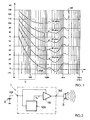
- Fig. 1 Shown schematically in Fig. 1 is a diagram with curves of equal loudness - as per ISO standard 226(2003).
- the diagram shows that the perceived loudness is strongly frequency-dependent. This frequency dependence itself is in turn sound-pressure-dependent, which means that different frequency dependencies exist for different levels. For this reason, the frequency spectrum X(f SA ) of the sound must be determined if statements are to be made about the perception of a sound event. Furthermore, a time behavior of a sound event as well as a sound event that extends over multiple frequency groups (overtones) also have an effect on the perception of loudness. In order to be able to quantify the perceived loudness of which Fig. 1 shows a graph of the loudness level (with phon as the unit of measure) as a function of frequency.
- the curves with equal perceived loudness level (e.g. 20 phon) represented in Fig. 1 show that the sound pressure dB with a bass frequency component B - also called bass portion B - rises sharply with decreasing frequency below approximately 200 Hz.
- a bass frequency component B - also called bass portion B - rises sharply with decreasing frequency below approximately 200 Hz.
- a significantly higher sound pressure dB as compared to a frequency of 1 kHz.
- a correspondingly higher electrical power is required to generate the high sound pressure dB of the bass portion B, when the sound event is reproduced with a loudspeaker.
- a sound pressure of approximately 20 dB must be generated for the frequency of 2 kHz.
- a sound pressure of 90 dB must be generated for the frequency of 20 Hz. Consequently, more electrical power must be applied for the bass portion B in the low-frequency range in order to produce the same perception of loudness in the human ear as at mid-range or high audio frequencies.
- the required electrical power depends on an efficiency and/or a directional characteristic of a loudspeaker.
- tweeters can have a somewhat higher efficiency than woofers.
- the higher the frequency the more the sound is directed and the power theoretically increases at the listening point.
- the radiated power can decrease when the wavelength of the frequency is smaller than the membrane radius.
- the acoustical space can influence the sound pressure in a frequency-dependent manner. For example, a pressure chamber effect occurs in a motor vehicle. When all physical effects that act are taken into account, the majority of the electrical power is required for the bass portion B at the same perceived loudness.
- Fig. 2 schematically shows a device 1 for reproducing an audio signal S A .
- the device 1 is, for example, an infotainment system of a motor vehicle or a portable player for the audio signal S A .
- the device 1 has a first interface 101 for connection to a rechargeable battery 2 as electrical storage device.
- the device 1 also has a second interface 102 for connection to a loudspeaker 3.
- the loudspeaker 3 is connected directly to a connection of the second interface 2 through cables. It is also possible to connect the loudspeaker 3 to the second interface 102 through a subwoofer amplifier (not shown).
- the device 1 of the exemplary embodiment from Fig. 1 has an amplifier 110 that is connected to the second interface 102 and is designed to amplify the audio signal S A .
- the amplifier 110 is connected to the rechargeable battery 2 through the first interface 101.
- the device 1 from Fig. 1 has a control device 120, which is connected to the first interface 101 and to the amplifier 110.
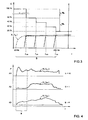
- a charge state C of the rechargeable battery 2 is shown at 20%, 30%, 40%, 50% and 100% charge.
- the charge state C with more than 50% is associated with a normal mode M N and a charge state C with less than 50% is associated with an energy saving mode M s of the device 1.
- the control device 120 from Fig. 2 is designed to reduce a power consumption from the rechargeable battery 2 for reproduction of the audio signal S A in the energy saving mode M s as compared to the normal mode M N .
- the bass portion B of the audio signal S A is reduced in energy saving mode M s by the audio signal S A being high-pass filtered.
- the frequency response of the filtering is shown for different threshold frequencies f G1 , f G2 , f G3 , f G4 .
- the audio signal S A is output with reduced bass portion B after the high-pass filtering.
- the control device 120 in Fig. 2 is configured to determine the charge state C. For example, an electrical quantity of the rechargeable battery 2, such as the rechargeable battery voltage or its behavior over time, is measured for this purpose.
- the control device 120 is configured to control the reduction in the bass portion B based on a decrease in the charge state C of the rechargeable battery 2.
- the reduction in the bass portion B is accomplished by filtering.
- a digital and/or analog high-pass filtering is performed by the control device 120.
- the control device 120 has a controllable filter function.
- the high-pass filter is activated or deactivated as a function of the charge state C. For instance, the high-pass filter is deactivated at a charge state C above 50%.
- the high-pass filtering can be controlled by the control device 120 in that a cut-off frequency f G1 , f G2 , f G3 , f G4 of the high-pass filtering can be altered.
- the high-pass filtering is deactivated in the normal mode M N at a charge state C above 50%.
- a first cut-off frequency value f G1 is associated with a charge state C between 40% and 50%.
- a second cut-off frequency value f G2 is associated with a charge state C between 30% and 40%.
- a third cut-off frequency value f G3 is associated with a charge state C between 20% and 30%.
- a fourth cut-off frequency value f G4 - for example 200 Hz - is associated with a charge state C below 20%.
- the cut-off frequencies f G1 , f G2 , f G3 , f G4 are controlled as a function of the charge state C by means of a step function in the exemplary embodiment from Fig. 3 .
- a proportional dependency may be provided. It is likewise possible to deactivate a subwoofer amplifier (not shown in Fig. 3 ) in energy saving mode M s .
- additional input quantities can be analyzed for controlling the reduction, as is explained in detail in the description of Fig. 5 .
- the control device 120 has a connection to a database (130 in Fig. 5 , not shown in Fig. 4 ) for this purpose.
- the database has audio files A 1 , A 2 , A 3 and metadata associated with each audio file A 1 , A 2 , A 3 .
- an energy value E is included in the metadata.
- the diagram from Fig. 4 schematically shows one frequency spectrum X(f A1 ), X(f A2 ), X(f A3 ) for each audio file A 1 , A 2 , A 3 and an associated energy value E stored in the database.
- the applicable energy value E is determined on the basis of a power P in the bass portion B of the spectrum X(f A1 ), X(f A2 ), X(f A3 ). To this end, the power P is acquired as the average over the entire length of the audio file A 1 , A 2 , A 3 , for example.
- a device 1 for reproducing an audio signal S A is explained in detail.
- the device 1 has a control unit 120, which is connected through a first interface 101 to a rechargeable battery 2, Accu.
- the device has an amplifier 110, AMP, which can be connected to a loudspeaker 3 through a second interface 102.
- the amplifier 110 can have multiple amplifier units, and is supplied with the current I Audio from the rechargeable battery 2.
- a subwoofer amplifier unit can additionally be activated and deactivated by means of the control signal SubOff.
- the amplifier 110 has the function of outputting the amplified audio signal S A to the loudspeaker 3.
- the device 1 has a control unit 120 for outputting the audio signal S A to the amplifier 110.
- the control device 120 is configured to operate a normal mode M N and an energy saving mode M S .
- the control device 120 is configured to generate control signals associated with the normal mode M N and the energy saving mode M S .
- the activation and deactivation of normal mode M N and energy saving mode M S is accomplished by means of input signals, such as an input by a user by means of an input unit 4 and/or a monitoring signal of an energy storage device 2 - such as an output voltage of a rechargeable battery - and/or a position-dependent signal from a navigation unit - such as a distance to a destination of a route.
- the energy saving mode M S is activated and deactivated as a function of the said input signals, wherein in energy saving mode M S an power consumption from the energy storage device 2 for reproduction of the audio signal S A is reduced as compared to normal mode M N .
- the music played in an electric motor vehicle is meant to be manipulated as a function of the charge state C of the rechargeable lithium-ion battery in such a manner that low-power titles can be played as needed or the music played can be altered/rid of high-power low frequencies by filtering.
- the energy saved in the rechargeable battery 2 by the device 1 can benefit the range of the motor vehicle.
- a loudness adjustment can also take place.
- the electrical power consumption of a music system in an electric vehicle depends largely on the playing loudness and the frequency spectrum X(f SA ) of the audio signal S A that is output.
- the acoustic power emitted through the loudspeaker 3 is directly related to the electrical power. Since the range of an electric vehicle depends on the charge state C of the rechargeable battery 2, the range is increased when the music system, as an energy consumer, conserves current I Audio for amplification of the audio signal S A to be output.
- control unit 120 is connected to multiple audio signal sources 130, 140.
- a database 130, DB connected through an interface or a network permits the selection and output of an audio file as the audio signal S A .
- a receiving device 140, RX is designed for audio reception, in particular via radio.
- the receiving device 140, RX has, for example, a UHF receiver or a DAB receiver or the like.
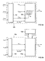
- Fig. 5a shows an exemplary embodiment of a control device 120 with an analysis unit 121 and a digital and/or analog filter 125. Electrical energy can be taken from the audio signal S A by means of filtering by the filter 125.
- the filter 125 preferably has a high-pass filter or a band-pass filter, which acts on the audio signal S A .
- the audio signal S A here comes from any desired source, such as a receiving device 140, a CD player or an MP3 player.
- a receiving device 140 such as a receiving device 140, a CD player or an MP3 player.
- a cut-off frequency f G of the filter 125 is adjusted as a function of a charge state C of the rechargeable battery 2 and/or of a remaining travel time/distance determined by the navigation unit 5, wherein the rechargeable battery 2 and the navigation unit 5 are shown schematically in Fig. 5 .
- the analysis unit 121 is designed to analyze the signal S INP from the input unit 4 and/or the signal S Accu from the rechargeable battery 2 and/or the signal S GPS from the navigation unit 5.
- the signal S INP from the input unit 4 is generated from input entered by the user on a touch screen.
- the signal S Accu from the rechargeable battery 2 is generated on the basis of, for instance, a voltage or a current budget of the rechargeable battery 2 and is dependent upon the charge state C of the rechargeable battery 2.
- the signal S GPS from the navigation unit 5 is determined as a function of, e.g., a remaining travel time or a distance to be traveled that has been determined by the navigation unit 5.
- a control signal C fG is output in order to adjust the cut-off frequency f G of the filter 125, wherein the filter 125 filters the bass portion B out of the input signal S DB (from the database 130) or out of the input signal S RX (from the receiving unit 140).
- the control can take place in accordance with the diagram for the exemplary embodiment in Fig. 3 by means of an LUT (Look Up Table).
- the exemplary embodiment from Fig. 5b makes it possible to select from among low-power music titles.
- the control unit 120 of the exemplary embodiment from Fig. 5b has an analysis unit 122 and a selection unit 126.
- the energy content of each music title in the database 130 is determined and an associated energy value E is stored in the database 130 with the metadata of the applicable music piece.
- the energy content is categorized from 1 to 10 by means of a scale of the energy values.
- This music title can be played when the rechargeable battery 2 is in critically low charge states C.
- audio files A 1 , A 2 , A 3 of titles in the database 130 are permitted to be output or not as a function of the charge state C of the rechargeable battery 2 and, where applicable, as a function of the remaining travel time/distance.
- the decision regarding permissibility is made on the basis of an energy threshold th E .
- all audio files A 1 , A 2 , A 3 from the database 130 that have an energy value E lower than the energy threshold th E are queried by means of a query Q(E).
- the audio files A(Q) dependent on the query Q(E) that are output are looped through the control unit 120, optionally are additionally filtered, and are output as audio signal S A with reduced bass portion B.
- the exemplary embodiments in Fig. 5a and Fig. 5b are combined with one another in a control unit 120 to good advantage.
- an input unit 4 is shown schematically as a touch screen.
- the touch screen 4 is shown with a graphical user interface with multiple widgets.
- a first icon 41 as input element permits the activation of a selection of only low power music pieces, which, for example, only have an energy value E below the energy threshold th E in accordance with the exemplary embodiment from Fig. 2 .
- a second icon 42 as input element permits the activation of filtering by a filter 125, which reduces the bass portion B.
- a consumption indicator 43 is shown as a widget, which symbolizes energy consumption in the form of a bar graph, for example. It is likewise possible for the widget 43 to have an input function, so that the user can specify the associated energy consumption directly by touching the bar 43 at a certain location.
- an upper loudness threshold is lowered when the charge state C of the rechargeable battery 2 drops.
- the threshold loudness can be reduced proportionately to the charge state C.
- audio reproduction can also be eliminated entirely, so that, for example, only predetermined audio content such as radio traffic reports, news, telephone, and navigational announcements are input as audio signal S A .
- the measures for reducing energy consumption can be combined with one another in any desired way.
- the energy consumption is calculated as a function of the filter setting and/or the energy value E, and is fed to a central energy management system or the range information in an electric vehicle.
- the invention is not restricted to the embodiment variants shown in Figures 1 through 6 .
- the remaining play time for audio files is then displayed to'the user.
- the functionality of the device 1 from Fig. 5 can be used for an electric vehicle.
Landscapes
- Engineering & Computer Science (AREA)
- Power Engineering (AREA)
- Multimedia (AREA)
- Signal Processing (AREA)
- Circuit For Audible Band Transducer (AREA)
- Fittings On The Vehicle Exterior For Carrying Loads, And Devices For Holding Or Mounting Articles (AREA)
Abstract
characterized in that
- a normal mode (MN) is deactivated and an energy saving mode (MS) is activated, wherein an power consumption from the energy storage device (2) for reproduction of the audio signal (SA) is reduced in the energy saving mode (MS) as compared to the normal mode (MN),
- in the energy saving mode (MS) a bass frequency component (B) of a frequency spectrum (X(fSA)) of the audio signal (SA) is reduced and the audio signal (SA) is output with reduced bass frequency component (B),
- a charge state (C) of the energy storage device (2) is ascertained, and
- the reduction in the bass frequency component (B) is controlled based on a decrease in the charge state (C) of the energy storage device (2).
Description
- The present invention concerns a device and a method for reproducing an audio signal.
- So called infotainment systems are known for motor vehicles. An infotainment system is configured to reproduce an audio signal.
- The object of the invention is to improve a device for reproducing an audio signal to the greatest extent possible.
- This object is attained by a device with the features of
independent claim 1. Advantageous developments are the subject matter of dependent claims, and are contained in the description. - Accordingly, a device is provided for reproducing an audio signal. The device has a first interface for connection to an energy storage device. The energy storage device comprises, for example, a battery or a fuel cell or preferably a rechargeable battery. The first interface preferable has connections for energy supply and/or signal connections.
- The device has a second interface for connection to a loudspeaker. The second interface is preferably a preamplifier output and/or a final amplifier output for outputting the audio signal. For example, the loudspeaker is connected to the second interface by means of a cable. It is likewise possible for the loudspeaker to be connected to the second interface through an amplifier, such as a subwoofer.
- The device has an amplifier, which is connected to the second interface and is designed to amplify the audio signal. The amplifier is, for example, a preamplifier or a power amplifier. The amplifier of the device is connectable to the energy storage device for operation.
- The device has a control device, which is connected to the first interface and to the amplifier. The control device preferably has a computing unit, for example a microcontroller and/or a signal processor and/or a CPU for executing a control program, wherein the control program provides control functions of the control device.
- The control device is configured to operate a normal mode and an energy saving mode. In energy saving mode, a power consumption of electrical energy from the energy storage device for reproduction of the audio signal is reduced as compared to the normal mode.
- The control device is configured, in the energy saving mode, to reduce the bass frequency component of a frequency spectrum of the audio signal and to output the audio signal through the second interface with reduced bass frequency component.
- The control device is designed to determine a charge state of the energy storage device. For example, a digital or analog charge state signal is transmitted from the energy storage device to the control device for determining the charge state.
- The control device is designed to control the reduction in the bass frequency component based on a decrease in the charge state of the energy storage device. The control device is designed to reduce the bass frequency component by means of a function when there is a decrease in the charge state. For example, the bass frequency component is reduced proportionately or by means of an LUT (Look Up Table).
- The invention has the additional object of specifying a method as greatly improved as possible for reproducing an audio signal.
- This object is attained by the method with the features of independent claim 7. Advantageous developments are contained in the description.
- Accordingly, a method is provided for controlling reproduction of an audio signal. The audio signal is reproduced by a device that is operated by means of an energy storage device.
- In the method, a normal mode is deactivated and an energy saving mode is activated, wherein in energy saving mode a power consumption from the energy storage device for reproduction of the audio signal is reduced as compared to the normal mode.
- In the energy saving mode, a bass frequency component of a frequency spectrum of the audio signal is reduced and the audio signal is output with reduced bass frequency component.
- Preferably, a charge state of the energy storage device is determined during the energy saving mode.
- The reduction in the bass frequency component is controlled based on a decrease in the charge state of the energy storage device.
- The developments described below relate to the device as well as to the method for reproducing an audio signal.
- According to a preferred development, provision is made for the control device to be connected to a database with stored audio files. Metadata associated with the audio files are stored in the database. Such metadata are, for instance, ID3 tags and other data as applicable.
- Preferably an energy value for each audio file is stored as an item of the metadata. The energy value is based on the bass frequency component of a frequency spectrum of the applicable audio file. For instance, the energy value is determined using a transformation in the frequency range and stored.
- Preferably the control device is configured to determine an energy threshold based on the charge state of the energy storage device. In a further development, the control device is configured to evaluate at least one additional input quantity for determining the energy threshold. For example, the additional input quantity is dependent on other electrical devices - such as an electric motor or a solar cell - that affect the charge state of the energy storage device. Preferably a distance to a destination or a remaining travel time of an electric vehicle is used for determining the energy threshold.
- For controlling the bass frequency component, preferably the control device is configured to determine an audio file to be output based on the energy threshold and based on the associated energy value of the audio file from the database, and to output the audio file as the audio signal.
- According to another development, the control device is configured to use a digital or analog filter for filtering the audio signal to be output in order to reduce the bass frequency component. Such a filter is, for example, an analog or digital high-pass filter or band-pass filter. Advantageously, the filtering by the filter is combined with the above-described selection using the energy threshold.
- In an advantageous embodiment, the control device is configured to determine a threshold frequency of the filter based on the charge state of the energy storage device. Preferably, the threshold frequency of the filter is increased for low frequencies of the audio signal as the charge state decreases.
- In an especially advantageous development, the control device is configured to determine a current position and a route to a destination with a distance to the destination. The distance to the destination preferably is determined by GPS (Global Positioning System). The distance between the current position and the destination is advantageously determined thereby. The necessary charge state for this range is determined on the basis of the distance. For example, a difference is ascertained between the current charge state and the necessary charge state for reaching the destination, and the reduction in the bass frequency component is controlled by means of the ascertained difference. Therefore, the control device preferably is configured to control the reduction in the bass frequency component based on the current charge state and the distance to the destination.
- In another advantageous embodiment, the control device is configured to activate the energy saving mode based on an input through an input unit.
- The variant embodiments described above are especially advantageous, both individually and in combination. All embodiments may be combined with one another. Some possible combinations are explained in the description of the drawings. However, these possibilities of combinations of the variant embodiment introduced there are not exhaustive.
- The invention is explained in detail below through exemplary embodiments with reference to drawings.
- The figures show
- Fig. 1
- a schematic diagram with curves of equal loudness,
- Fig. 2
- a schematic block diagram,
- Fig. 3
- a schematic diagram for an exemplary embodiment,
- Fig. 4
- another schematic diagram for another exemplary embodiment,
- Fig. 5
- a schematic representation of a device for reproducing an audio signal,
- Fig. 5a
- a schematic embodiment of a control device,
- Fig. 5b
- another schematic embodiment of another control device, and
- Fig. 6
- a schematic embodiment of an input unit.
- Shown schematically in
Fig. 1 is a diagram with curves of equal loudness - as per ISO standard 226(2003). The diagram shows that the perceived loudness is strongly frequency-dependent. This frequency dependence itself is in turn sound-pressure-dependent, which means that different frequency dependencies exist for different levels. For this reason, the frequency spectrum X(fSA) of the sound must be determined if statements are to be made about the perception of a sound event. Furthermore, a time behavior of a sound event as well as a sound event that extends over multiple frequency groups (overtones) also have an effect on the perception of loudness. In order to be able to quantify the perceived loudness of whichFig. 1 shows a graph of the loudness level (with phon as the unit of measure) as a function of frequency. For example, it is known to use an A-filter for evaluation, wherein the frequency filter used in each case can be appended to the dB value (dB = decibels) in parentheses, as for example 20 dB(A). The curves have regions est extrapolated by calculation. - The curves with equal perceived loudness level (e.g. 20 phon) represented in
Fig. 1 show that the sound pressure dB with a bass frequency component B - also called bass portion B - rises sharply with decreasing frequency below approximately 200 Hz. In order to reproduce a sound event in the bass frequency component B, it is thus necessary to generate a significantly higher sound pressure dB as compared to a frequency of 1 kHz. Thus, a correspondingly higher electrical power is required to generate the high sound pressure dB of the bass portion B, when the sound event is reproduced with a loudspeaker. If, for example, a sound event with a bandwidth of 20 Hz to 2 kHz is to be reproduced with a perceived loudness level of 20 phon, then a sound pressure of approximately 20 dB must be generated for the frequency of 2 kHz. In contrast, a sound pressure of 90 dB must be generated for the frequency of 20 Hz. Consequently, more electrical power must be applied for the bass portion B in the low-frequency range in order to produce the same perception of loudness in the human ear as at mid-range or high audio frequencies. - Furthermore, the required electrical power depends on an efficiency and/or a directional characteristic of a loudspeaker. For example, tweeters can have a somewhat higher efficiency than woofers. The higher the frequency, the more the sound is directed and the power theoretically increases at the listening point. The lower the frequency becomes, the more omnidirectional the sound becomes, requiring more power for the same sound pressure at the listening point. Furthermore, the radiated power can decrease when the wavelength of the frequency is smaller than the membrane radius. Moreover, the acoustical space can influence the sound pressure in a frequency-dependent manner. For example, a pressure chamber effect occurs in a motor vehicle. When all physical effects that act are taken into account, the majority of the electrical power is required for the bass portion B at the same perceived loudness.
-
Fig. 2 schematically shows adevice 1 for reproducing an audio signal SA. Thedevice 1 is, for example, an infotainment system of a motor vehicle or a portable player for the audio signal SA. Thedevice 1 has afirst interface 101 for connection to arechargeable battery 2 as electrical storage device. Thedevice 1 also has asecond interface 102 for connection to aloudspeaker 3. For example, theloudspeaker 3 is connected directly to a connection of thesecond interface 2 through cables. It is also possible to connect theloudspeaker 3 to thesecond interface 102 through a subwoofer amplifier (not shown). Thedevice 1 of the exemplary embodiment fromFig. 1 has anamplifier 110 that is connected to thesecond interface 102 and is designed to amplify the audio signal SA. For operation, theamplifier 110 is connected to therechargeable battery 2 through thefirst interface 101. In addition, thedevice 1 fromFig. 1 has acontrol device 120, which is connected to thefirst interface 101 and to theamplifier 110. - An exemplary embodiment is explained in detail with reference to the diagram in
Fig. 3 . A charge state C of therechargeable battery 2 is shown at 20%, 30%, 40%, 50% and 100% charge. In the exemplary embodiment fromFig. 3 , the charge state C with more than 50% is associated with a normal mode MN and a charge state C with less than 50% is associated with an energy saving mode Ms of thedevice 1. Also shown by way of example is the frequency spectrum X(fSA) of the audio signal SA with respect to the frequency f. Thecontrol device 120 fromFig. 2 is designed to reduce a power consumption from therechargeable battery 2 for reproduction of the audio signal SA in the energy saving mode Ms as compared to the normal mode MN. In the exemplary embodiment fromFig. 3 the bass portion B of the audio signal SA is reduced in energy saving mode Ms by the audio signal SA being high-pass filtered. InFig. 3 , the frequency response of the filtering is shown for different threshold frequencies fG1, fG2, fG3, fG4. The audio signal SA is output with reduced bass portion B after the high-pass filtering. - The
control device 120 inFig. 2 is configured to determine the charge state C. For example, an electrical quantity of therechargeable battery 2, such as the rechargeable battery voltage or its behavior over time, is measured for this purpose. Thecontrol device 120 is configured to control the reduction in the bass portion B based on a decrease in the charge state C of therechargeable battery 2. In the exemplary embodiment fromFig. 3 , the reduction in the bass portion B is accomplished by filtering. In the exemplary embodiment fromFig. 3 a digital and/or analog high-pass filtering is performed by thecontrol device 120. In this embodiment, thecontrol device 120 has a controllable filter function. In another embodiment the high-pass filter is activated or deactivated as a function of the charge state C. For instance, the high-pass filter is deactivated at a charge state C above 50%. - In the exemplary embodiment from
Fig. 3 , the high-pass filtering can be controlled by thecontrol device 120 in that a cut-off frequency fG1, fG2, fG3, fG4 of the high-pass filtering can be altered. In the exemplary embodiment fromFig. 3 the high-pass filtering is deactivated in the normal mode MN at a charge state C above 50%. A first cut-off frequency value fG1 is associated with a charge state C between 40% and 50%. A second cut-off frequency value fG2 is associated with a charge state C between 30% and 40%. A third cut-off frequency value fG3 is associated with a charge state C between 20% and 30%. In contrast, a fourth cut-off frequency value fG4 - for example 200 Hz - is associated with a charge state C below 20%. The cut-off frequencies fG1, fG2, fG3, fG4 are controlled as a function of the charge state C by means of a step function in the exemplary embodiment fromFig. 3 . Alternatively, a proportional dependency may be provided. It is likewise possible to deactivate a subwoofer amplifier (not shown inFig. 3 ) in energy saving mode Ms. In addition to the charge state C, additional input quantities can be analyzed for controlling the reduction, as is explained in detail in the description ofFig. 5 . - Another exemplary embodiment is explained using the graph in
Fig. 4 . Thecontrol device 120 has a connection to a database (130 inFig. 5 , not shown inFig. 4 ) for this purpose. The database has audio files A1, A2, A3 and metadata associated with each audio file A1, A2, A3. In this design, an energy value E is included in the metadata. The diagram fromFig. 4 schematically shows one frequency spectrum X(fA1), X(fA2), X(fA3) for each audio file A1, A2, A3 and an associated energy value E stored in the database. Thus, the energy value associated with the first data file A1 is E=10, the energy value associated with the second audio file A2 is E=1, and the energy value associated with the third audio file A3 is E=4. The applicable energy value E is determined on the basis of a power P in the bass portion B of the spectrum X(fA1), X(fA2), X(fA3). To this end, the power P is acquired as the average over the entire length of the audio file A1, A2, A3, for example. - In
Fig. 5 , adevice 1 for reproducing an audio signal SA is explained in detail. Thedevice 1 has acontrol unit 120, which is connected through afirst interface 101 to arechargeable battery 2, Accu. In addition, the device has anamplifier 110, AMP, which can be connected to aloudspeaker 3 through asecond interface 102. Theamplifier 110 can have multiple amplifier units, and is supplied with the current IAudio from therechargeable battery 2. In the exemplary embodiment fromFig. 5 , a subwoofer amplifier unit can additionally be activated and deactivated by means of the control signal SubOff. Theamplifier 110 has the function of outputting the amplified audio signal SA to theloudspeaker 3. - The
device 1 has acontrol unit 120 for outputting the audio signal SA to theamplifier 110. Thecontrol device 120 is configured to operate a normal mode MN and an energy saving mode MS. For this purpose, thecontrol device 120 is configured to generate control signals associated with the normal mode MN and the energy saving mode MS. The activation and deactivation of normal mode MN and energy saving mode MS is accomplished by means of input signals, such as an input by a user by means of aninput unit 4 and/or a monitoring signal of an energy storage device 2 - such as an output voltage of a rechargeable battery - and/or a position-dependent signal from a navigation unit - such as a distance to a destination of a route. The energy saving mode MS is activated and deactivated as a function of the said input signals, wherein in energy saving mode MS an power consumption from theenergy storage device 2 for reproduction of the audio signal SA is reduced as compared to normal mode MN. - By means of the exemplary embodiment from
Fig. 5 , the music played in an electric motor vehicle is meant to be manipulated as a function of the charge state C of the rechargeable lithium-ion battery in such a manner that low-power titles can be played as needed or the music played can be altered/rid of high-power low frequencies by filtering. In this way, the energy saved in therechargeable battery 2 by thedevice 1 can benefit the range of the motor vehicle. In addition, a loudness adjustment can also take place. - Music systems in electric motor vehicles consume electrical energy. If the energy should rather be used for the range of the electric vehicle instead, the option exists of manually turning off the music system entirely. But if vehicle occupants do not wish to forego the enjoyment of music altogether, the energy that is available must be distributed intelligently. When the rechargeable battery has low charge, only low-power music is output at the
loudspeaker 3 by thedevice 1. The low-power music is obtained by categorizing the music pieces and/or by filtering out high-power portions of the frequency spectrum. This has a direct effect on the acoustic power and, at the same time, on the electrical power consumption. - The electrical power consumption of a music system in an electric vehicle depends largely on the playing loudness and the frequency spectrum X(fSA) of the audio signal SA that is output. The acoustic power emitted through the
loudspeaker 3 is directly related to the electrical power. Since the range of an electric vehicle depends on the charge state C of therechargeable battery 2, the range is increased when the music system, as an energy consumer, conserves current IAudio for amplification of the audio signal SA to be output. - In the exemplary embodiment from
Fig. 5 , thecontrol unit 120 is connected to multipleaudio signal sources database 130, DB connected through an interface or a network permits the selection and output of an audio file as the audio signal SA. In contrast, a receivingdevice 140, RX is designed for audio reception, in particular via radio. The receivingdevice 140, RX has, for example, a UHF receiver or a DAB receiver or the like. -
Fig. 5a shows an exemplary embodiment of acontrol device 120 with ananalysis unit 121 and a digital and/oranalog filter 125. Electrical energy can be taken from the audio signal SA by means of filtering by thefilter 125. Thefilter 125 preferably has a high-pass filter or a band-pass filter, which acts on the audio signal SA. The audio signal SA here comes from any desired source, such as a receivingdevice 140, a CD player or an MP3 player. In the exemplary embodiment fromFig. 5a , a cut-off frequency fG of thefilter 125 is adjusted as a function of a charge state C of therechargeable battery 2 and/or of a remaining travel time/distance determined by thenavigation unit 5, wherein therechargeable battery 2 and thenavigation unit 5 are shown schematically inFig. 5 . - The
analysis unit 121 is designed to analyze the signal SINP from theinput unit 4 and/or the signal SAccu from therechargeable battery 2 and/or the signal SGPS from thenavigation unit 5. In the exemplary embodiment fromFig. 5a , the signal SINP from theinput unit 4 is generated from input entered by the user on a touch screen. The signal SAccu from therechargeable battery 2 is generated on the basis of, for instance, a voltage or a current budget of therechargeable battery 2 and is dependent upon the charge state C of therechargeable battery 2. The signal SGPS from thenavigation unit 5 is determined as a function of, e.g., a remaining travel time or a distance to be traveled that has been determined by thenavigation unit 5. - Using the input signals SINP, SAccu, SGPS the
analysis unit 121 generates a signal MN/MS for controlling an activation or deactivation of a normal mode MN and an energy saving mode MS. Furthermore, in the exemplary embodiment fromFig. 5a , a control signal CfG is output in order to adjust the cut-off frequency fG of thefilter 125, wherein thefilter 125 filters the bass portion B out of the input signal SDB (from the database 130) or out of the input signal SRX (from the receiving unit 140). For example, the control can take place in accordance with the diagram for the exemplary embodiment inFig. 3 by means of an LUT (Look Up Table). The lower the charge state C of therechargeable battery 2 is, the higher the cut-off frequency fG will be set, since low frequencies in a bass portion B of the spectrum X(fSA) consume more electrical energy. In addition, provision is made in the exemplary embodiment fromFig. 5 for the amplifier and the loudspeaker to be switched off for low frequencies on the basis of the energy saving mode MS and/or the threshold frequency fG. It is acoustically advantageous here for the cut-off frequency fG of thefilter 125 to be modified slowly over time, for example by means of a timer and/or as a function of the change state C over time of therechargeable battery 2. - The exemplary embodiment from
Fig. 5b makes it possible to select from among low-power music titles. Thecontrol unit 120 of the exemplary embodiment fromFig. 5b has ananalysis unit 122 and aselection unit 126. Preferably, the energy content of each music title in thedatabase 130 is determined and an associated energy value E is stored in thedatabase 130 with the metadata of the applicable music piece. For example, the energy content is categorized from 1 to 10 by means of a scale of the energy values. For example, E = 1 means very low power with a small bass portion B. This music title can be played when therechargeable battery 2 is in critically low charge states C. The energy value E = 10 means very high power with a large bass portion B. This music title is not played in critical charge states C. - If the user is listening to content from his
MP3 database 130, audio files A1, A2, A3 of titles in thedatabase 130 are permitted to be output or not as a function of the charge state C of therechargeable battery 2 and, where applicable, as a function of the remaining travel time/distance. In the exemplary embodiment fromFig. 5b the decision regarding permissibility is made on the basis of an energy threshold thE. For example, all audio files A1, A2, A3 from thedatabase 130 that have an energy value E lower than the energy threshold thE are queried by means of a query Q(E). The threshold is thE = 5, for example, so that only the second audio file A2 and the third audio file A3 are read out as per the exemplary embodiment inFig. 4 . The audio files A(Q) dependent on the query Q(E) that are output are looped through thecontrol unit 120, optionally are additionally filtered, and are output as audio signal SA with reduced bass portion B. The exemplary embodiments inFig. 5a and Fig. 5b are combined with one another in acontrol unit 120 to good advantage. - In
Fig. 6 aninput unit 4 is shown schematically as a touch screen. Thetouch screen 4 is shown with a graphical user interface with multiple widgets. Afirst icon 41 as input element permits the activation of a selection of only low power music pieces, which, for example, only have an energy value E below the energy threshold thE in accordance with the exemplary embodiment fromFig. 2 . Asecond icon 42 as input element permits the activation of filtering by afilter 125, which reduces the bass portion B. In addition, aconsumption indicator 43 is shown as a widget, which symbolizes energy consumption in the form of a bar graph, for example. It is likewise possible for thewidget 43 to have an input function, so that the user can specify the associated energy consumption directly by touching thebar 43 at a certain location. - In addition to the above-mentioned possibilities for reducing energy consumption, it is possible to reduce the loudness of the entire frequency spectrum X(fSA) of the audio signal SA in order to further reduce power consumption. Preferably, an upper loudness threshold is lowered when the charge state C of the
rechargeable battery 2 drops. For example, the threshold loudness can be reduced proportionately to the charge state C. If the energy situation is very critical, audio reproduction can also be eliminated entirely, so that, for example, only predetermined audio content such as radio traffic reports, news, telephone, and navigational announcements are input as audio signal SA. The measures for reducing energy consumption can be combined with one another in any desired way. The energy consumption is calculated as a function of the filter setting and/or the energy value E, and is fed to a central energy management system or the range information in an electric vehicle. - The invention is not restricted to the embodiment variants shown in
Figures 1 through 6 . For example, it is possible to provide for the reduction of energy consumption for a mobile, portable device, wherein the user can adjust the consumption through the entry of, for instance, predefined consumption levels. The remaining play time for audio files is then displayed to'the user. In especially advantageous manner, the functionality of thedevice 1 fromFig. 5 can be used for an electric vehicle. -
- 1
- device
- 101, 102
- Interface
- 110, AMP
- amplifier
- 120
- control unit
- 121, 122
- analysis unit
- 125
- filter
- 126
- selection unit
- 130, DB
- database
- 140, RX
- receiver
- 2, Accu
- energy storage device, rechargeable battery
- 3
- loudspeaker
- 4, Inp
- input unit, touch screen
- 41, 42
- input element, widget
- 43
- display element
- 5, GPS
- unit for position determination, navigation unit
- A1, A2, A3
- audio file
- B
- bass frequency component, bass portion
- C
- charge state
- E
- energy value
- est
- calculated curve
- f
- frequency
- fG1, fG2, fG3, fG4
- threshold frequency
- IAudio
- current
- MN
- normal mode
- MS
- energy saving mode
- P
- power
- SA
- audio signal
- SINP, SAccu, SGPS, SRX, SDB,
- signal
- CfG, Q(E), A(Q) SubOff
- control signal
- thE
- energy threshold
- X(fSA), X(fA1), X(fA2), X(fA3)
- frequency response, spectrum
Claims (7)
- Device (1) for reproducing an audio signal (SA),- with a first interface (101) for connection to an energy storage device (2), in particular to a rechargeable battery,- with a second interface (102) for connection to a loudspeaker (3),- with an amplifier (110) connectable to the second interface (102), wherein the amplifier (110) is configured to amplify the audio signal (SA), wherein the amplifier (110) is connectable to the energy storage device (2) for operation,- with a control device (120), which is connected to the first interface (101) and to the amplifier (110),characterized in that- the control device (120) is configured to operate a normal mode (MN) and an energy saving mode (MS), wherein in the energy saving mode (MS) power consumption from the energy storage device (2) for reproduction of the audio signal (SA) is reduced as compared to the normal mode (MN),- the control device (120) is configured to reduce a bass frequency component (B) of a frequency spectrum (X(fSA)) of the audio signal (SA) and to output the audio signal (SA) with the reduced bass frequency component (B) in the energy saving mode (MS),- the control device (120) is configured to determine a charge state (C) of the energy storage device (2),- the control device (120) is configured to control the reduction in the bass frequency component (B) based on a decrease in the charge state (C) of the energy storage device (2).
- Device (1) according to one of the preceding claims, characterized in that- the control device (120) is connectable to a database (130) with stored audio files (A1, A2, A3),- an energy value (E1, E2, E3) is stored for each audio file (A1, A2, A3), wherein the energy value (E1, E2, E3) is based on the bass frequency component (B) of a frequency spectrum (X(fA1), X(fA2), X(fA3)) of the audio file (A1, A2, A3),- the control device (120) is configured to determine an energy threshold (thE) based on the charge state (C) of the energy storage device (2),- the control device (120) is configured, for the purpose of controlling the bass frequency component (B), to ascertain an audio file (A1, A2, A3) to be output based on the associated energy value (E1, E2, E3) of the audio file (A1, A2, A3) and based on the energy threshold (thE), and to output the audio file (A1, A2, A3) as the audio signal (SA).
- Device (1) according to one of the preceding claims,
characterized in that- the control device (120) is configured to filter the audio signal to be output (SA) through a digital or analog filter (125) to reduce the bass frequency component (B). - Device (1) according to claim 3,
characterized in that- the control device (120) is configured to determine a threshold frequency (fG1, fG2, fG3, fG4) of the filter (125) based on the charge state (C) of the energy storage device (2). - Device (1) according to one of the preceding claims,
characterized in that- the control device (120) is configured to control the reduction in the bass frequency component (B) based on the charge state (C) and the distance of a certain distance to a destination. - Device (1) according to one of the preceding claims,
characterized in that- the control device (120) is configured to activate the energy saving mode (MS) based on an input through an input unit (4). - Method for controlling a reproduction of an audio signal (SA) of a device powered by an energy storage device (2),
characterized in that- a normal mode (MN) is deactivated and an energy saving mode (MS) is activated, wherein an power consumption from the energy storage device (2) for reproduction of the audio signal (SA) is reduced in the energy saving mode (MS) as compared to the normal mode (MN),- in the energy saving mode (MS) a bass frequency component (B) of a frequency spectrum (X(fSA)) of the audio signal (SA) is reduced and the audio signal (SA) is output with reduced bass frequency component (B),- a charge state (C) of the energy storage device (2) is ascertained, and- the reduction in the bass frequency component (B) is controlled based on a decrease in the charge state (C) of the energy storage device (2).
Priority Applications (5)
| Application Number | Priority Date | Filing Date | Title |
|---|---|---|---|
| EP11008245.0A EP2582037B1 (en) | 2011-10-12 | 2011-10-12 | Device and method for reproducing an audio signal |
| KR1020120112261A KR101447615B1 (en) | 2011-10-12 | 2012-10-10 | Device and method for reproducing an audio signal |
| JP2012226338A JP2013083983A (en) | 2011-10-12 | 2012-10-11 | Device and method for reproducing audio signal |
| CN201210387539.8A CN103050139B (en) | 2011-10-12 | 2012-10-12 | For equipment and the method for playing audio signal |
| US13/650,904 US9780739B2 (en) | 2011-10-12 | 2012-10-12 | Device and method for reproducing an audio signal |
Applications Claiming Priority (1)
| Application Number | Priority Date | Filing Date | Title |
|---|---|---|---|
| EP11008245.0A EP2582037B1 (en) | 2011-10-12 | 2011-10-12 | Device and method for reproducing an audio signal |
Publications (2)
| Publication Number | Publication Date |
|---|---|
| EP2582037A1 true EP2582037A1 (en) | 2013-04-17 |
| EP2582037B1 EP2582037B1 (en) | 2017-12-20 |
Family
ID=44799541
Family Applications (1)
| Application Number | Title | Priority Date | Filing Date |
|---|---|---|---|
| EP11008245.0A Active EP2582037B1 (en) | 2011-10-12 | 2011-10-12 | Device and method for reproducing an audio signal |
Country Status (5)
| Country | Link |
|---|---|
| US (1) | US9780739B2 (en) |
| EP (1) | EP2582037B1 (en) |
| JP (1) | JP2013083983A (en) |
| KR (1) | KR101447615B1 (en) |
| CN (1) | CN103050139B (en) |
Cited By (2)
| Publication number | Priority date | Publication date | Assignee | Title |
|---|---|---|---|---|
| WO2015047677A1 (en) * | 2013-09-30 | 2015-04-02 | Sonos, Inc. | Transitioning a networked playback device between operating modes |
| DE102023134291A1 (en) * | 2023-12-07 | 2025-06-12 | Bayerische Motoren Werke Aktiengesellschaft | Method for an electrically driven motor vehicle, computer program and/or computer-readable medium, data processing device and motor vehicle |
Families Citing this family (8)
| Publication number | Priority date | Publication date | Assignee | Title |
|---|---|---|---|---|
| US9247342B2 (en) | 2013-05-14 | 2016-01-26 | James J. Croft, III | Loudspeaker enclosure system with signal processor for enhanced perception of low frequency output |
| KR102437156B1 (en) * | 2015-11-24 | 2022-08-26 | 삼성전자주식회사 | Electronic device and method for processing voice signal according to state of electronic device |
| US10374566B2 (en) * | 2016-07-29 | 2019-08-06 | Maxim Integrated Products, Inc. | Perceptual power reduction system and method |
| KR102583931B1 (en) * | 2017-01-25 | 2023-10-04 | 삼성전자주식회사 | Sound output apparatus and control method thereof |
| WO2020033595A1 (en) | 2018-08-07 | 2020-02-13 | Pangissimo, LLC | Modular speaker system |
| CN112804616B (en) * | 2020-12-31 | 2022-05-17 | 青岛海信移动通信技术股份有限公司 | Mobile terminal and audio playback method thereof |
| US12351280B2 (en) * | 2021-09-28 | 2025-07-08 | Kawasaki Motors, Ltd. | Small planing watercraft and method of controlling small planing watercraft |
| FR3149266A1 (en) * | 2023-06-02 | 2024-12-06 | Psa Automobiles Sa | Method for managing the sound volume of an audio system of a motor vehicle |
Citations (3)
| Publication number | Priority date | Publication date | Assignee | Title |
|---|---|---|---|---|
| FR2707131A1 (en) * | 1993-06-30 | 1995-01-06 | Motorola Inc | Electronic device comprising an internal charge regulator for controlling the application of a charging current and associated method. |
| EP1024577A1 (en) * | 1997-09-26 | 2000-08-02 | Wellpine Communications Co., Ltd. | Power system |
| US20020044637A1 (en) * | 2000-10-18 | 2002-04-18 | Nec Corporation | Power circuit, power circuit control method and eletronic device using the power circuit |
Family Cites Families (18)
| Publication number | Priority date | Publication date | Assignee | Title |
|---|---|---|---|---|
| US4951002A (en) * | 1989-04-13 | 1990-08-21 | Plantronics, Inc. | Battery powered in-line amplifier |
| US5150415A (en) * | 1989-05-01 | 1992-09-22 | Motorola, Inc. | Volume control circuit using pulse modulation |
| US5029005A (en) * | 1990-04-25 | 1991-07-02 | Rca Licensing Corporation | Apparatus for the muting of an audio power amplifier in a standby mode |
| JPH06244644A (en) * | 1993-02-15 | 1994-09-02 | Pioneer Electron Corp | Mute device for car audio system |
| US5434922A (en) * | 1993-04-08 | 1995-07-18 | Miller; Thomas E. | Method and apparatus for dynamic sound optimization |
| JPH09223938A (en) * | 1996-02-19 | 1997-08-26 | Kawai Musical Instr Mfg Co Ltd | Electronics |
| JP3569266B2 (en) * | 2002-03-22 | 2004-09-22 | 株式会社東芝 | Reproduction device and power saving method |
| US7715574B2 (en) * | 2004-08-04 | 2010-05-11 | James E. Aikins | Audio apparatus for vessel |
| JP2006079782A (en) * | 2004-09-13 | 2006-03-23 | Sony Corp | Playback device, playback method, and recording medium |
| JP2008537374A (en) * | 2005-03-15 | 2008-09-11 | コーニンクレッカ フィリップス エレクトロニクス エヌ ヴィ | Audio data processing apparatus, audio data processing method, program element, and computer-readable medium |
| US20060262938A1 (en) * | 2005-05-18 | 2006-11-23 | Gauger Daniel M Jr | Adapted audio response |
| JP2007004600A (en) * | 2005-06-24 | 2007-01-11 | Toshiba Corp | Electronic device and speaker drive control method |
| KR101135243B1 (en) | 2005-11-04 | 2012-04-12 | 내셔날유니버서티오브싱가폴 | A device and a method of playing audio clips |
| JP2007280033A (en) * | 2006-04-06 | 2007-10-25 | Sharp Corp | Content reproduction apparatus, program, and recording medium |
| US20080129520A1 (en) * | 2006-12-01 | 2008-06-05 | Apple Computer, Inc. | Electronic device with enhanced audio feedback |
| JP5020105B2 (en) * | 2008-01-10 | 2012-09-05 | 中国電力株式会社 | Electric vehicle power saving operation support device and electric vehicle equipped with the same |
| US20090257601A1 (en) * | 2008-04-12 | 2009-10-15 | Marvin Andrew Motsenbocker | Acoustic speaker system with strong bass capability |
| WO2010041147A2 (en) * | 2008-10-09 | 2010-04-15 | Futureacoustic | A music or sound generation system |
-
2011
- 2011-10-12 EP EP11008245.0A patent/EP2582037B1/en active Active
-
2012
- 2012-10-10 KR KR1020120112261A patent/KR101447615B1/en not_active Expired - Fee Related
- 2012-10-11 JP JP2012226338A patent/JP2013083983A/en active Pending
- 2012-10-12 CN CN201210387539.8A patent/CN103050139B/en active Active
- 2012-10-12 US US13/650,904 patent/US9780739B2/en active Active
Patent Citations (3)
| Publication number | Priority date | Publication date | Assignee | Title |
|---|---|---|---|---|
| FR2707131A1 (en) * | 1993-06-30 | 1995-01-06 | Motorola Inc | Electronic device comprising an internal charge regulator for controlling the application of a charging current and associated method. |
| EP1024577A1 (en) * | 1997-09-26 | 2000-08-02 | Wellpine Communications Co., Ltd. | Power system |
| US20020044637A1 (en) * | 2000-10-18 | 2002-04-18 | Nec Corporation | Power circuit, power circuit control method and eletronic device using the power circuit |
Cited By (6)
| Publication number | Priority date | Publication date | Assignee | Title |
|---|---|---|---|---|
| WO2015047677A1 (en) * | 2013-09-30 | 2015-04-02 | Sonos, Inc. | Transitioning a networked playback device between operating modes |
| US10055003B2 (en) | 2013-09-30 | 2018-08-21 | Sonos, Inc. | Playback device operations based on battery level |
| US10871817B2 (en) | 2013-09-30 | 2020-12-22 | Sonos, Inc. | Synchronous playback with battery-powered playback device |
| US11543876B2 (en) | 2013-09-30 | 2023-01-03 | Sonos, Inc. | Synchronous playback with battery-powered playback device |
| US12164362B2 (en) | 2013-09-30 | 2024-12-10 | Sonos, Inc. | Synchronous playback with battery-powered playback device |
| DE102023134291A1 (en) * | 2023-12-07 | 2025-06-12 | Bayerische Motoren Werke Aktiengesellschaft | Method for an electrically driven motor vehicle, computer program and/or computer-readable medium, data processing device and motor vehicle |
Also Published As
| Publication number | Publication date |
|---|---|
| KR101447615B1 (en) | 2014-10-06 |
| JP2013083983A (en) | 2013-05-09 |
| US20130094665A1 (en) | 2013-04-18 |
| CN103050139A (en) | 2013-04-17 |
| US9780739B2 (en) | 2017-10-03 |
| KR20130039688A (en) | 2013-04-22 |
| CN103050139B (en) | 2015-09-16 |
| EP2582037B1 (en) | 2017-12-20 |
Similar Documents
| Publication | Publication Date | Title |
|---|---|---|
| EP2582037B1 (en) | Device and method for reproducing an audio signal | |
| EP2487930B1 (en) | Sound signal output apparatus and sound signal output method | |
| US9413322B2 (en) | Audio loudness control system | |
| CN103188587A (en) | Sound system with individual playback zones | |
| KR20120036854A (en) | Method and circuit for controlling an output of an audio signal of a battery-powered device | |
| WO2012087314A1 (en) | Audio control system | |
| US7756280B2 (en) | Audio processing system and method for automatically adjusting volume | |
| CN203402057U (en) | Warning tone setting system of vehicle and vehicle | |
| US11876497B2 (en) | Automatic progressive transition of volume adaptation to environmental noise | |
| CN105006240A (en) | Music sound control method and system based on audio playing device | |
| CN106941649B (en) | Method for changing audio output mode of vehicle and apparatus therefor | |
| CN111580774B (en) | Sound effect adjusting method, device, equipment and storage medium | |
| KR101051036B1 (en) | Apparatus and method for controlling sound quality of audio equipments according to the hearing of individual users | |
| US20050195998A1 (en) | Simultaneous audio playback device | |
| KR100999647B1 (en) | Volume automatic control method and system | |
| WO2007116802A1 (en) | Output control device, output control method, output control program, and recording medium | |
| KR20150073538A (en) | Hearing aid device of playing audible advertisement or audible data | |
| US20070253571A1 (en) | Sound reproduction device and method for hearing protection in an ambient environment | |
| WO2015185406A1 (en) | Dynamic configuring of a multichannel sound system for power saving | |
| JP6794722B2 (en) | Vehicle interior sound environment notification device and vehicle interior sound environment notification method | |
| CN202736481U (en) | Device preventing auditory fatigue | |
| US12026428B2 (en) | Audio video navigation system for vehicle and method for playing media thereof | |
| US20070110261A1 (en) | Audio processing system with function of automatic gain control and method thereof | |
| US20070076895A1 (en) | Audio processing system and method for hearing protection | |
| CN118646981A (en) | Audio pressure detection method, device, electronic equipment, vehicle and storage medium |
Legal Events
| Date | Code | Title | Description |
|---|---|---|---|
| PUAI | Public reference made under article 153(3) epc to a published international application that has entered the european phase |
Free format text: ORIGINAL CODE: 0009012 |
|
| 17P | Request for examination filed |
Effective date: 20121025 |
|
| AK | Designated contracting states |
Kind code of ref document: A1 Designated state(s): AL AT BE BG CH CY CZ DE DK EE ES FI FR GB GR HR HU IE IS IT LI LT LU LV MC MK MT NL NO PL PT RO RS SE SI SK SM TR |
|
| AX | Request for extension of the european patent |
Extension state: BA ME |
|
| 17Q | First examination report despatched |
Effective date: 20160829 |
|
| GRAP | Despatch of communication of intention to grant a patent |
Free format text: ORIGINAL CODE: EPIDOSNIGR1 |
|
| INTG | Intention to grant announced |
Effective date: 20170703 |
|
| GRAS | Grant fee paid |
Free format text: ORIGINAL CODE: EPIDOSNIGR3 |
|
| GRAA | (expected) grant |
Free format text: ORIGINAL CODE: 0009210 |
|
| AK | Designated contracting states |
Kind code of ref document: B1 Designated state(s): AL AT BE BG CH CY CZ DE DK EE ES FI FR GB GR HR HU IE IS IT LI LT LU LV MC MK MT NL NO PL PT RO RS SE SI SK SM TR |
|
| REG | Reference to a national code |
Ref country code: GB Ref legal event code: FG4D |
|
| REG | Reference to a national code |
Ref country code: CH Ref legal event code: EP |
|
| REG | Reference to a national code |
Ref country code: IE Ref legal event code: FG4D |
|
| REG | Reference to a national code |
Ref country code: AT Ref legal event code: REF Ref document number: 957239 Country of ref document: AT Kind code of ref document: T Effective date: 20180115 |
|
| REG | Reference to a national code |
Ref country code: DE Ref legal event code: R096 Ref document number: 602011044286 Country of ref document: DE |
|
| REG | Reference to a national code |
Ref country code: NL Ref legal event code: MP Effective date: 20171220 |
|
| PG25 | Lapsed in a contracting state [announced via postgrant information from national office to epo] |
Ref country code: SE Free format text: LAPSE BECAUSE OF FAILURE TO SUBMIT A TRANSLATION OF THE DESCRIPTION OR TO PAY THE FEE WITHIN THE PRESCRIBED TIME-LIMIT Effective date: 20171220 Ref country code: FI Free format text: LAPSE BECAUSE OF FAILURE TO SUBMIT A TRANSLATION OF THE DESCRIPTION OR TO PAY THE FEE WITHIN THE PRESCRIBED TIME-LIMIT Effective date: 20171220 Ref country code: NO Free format text: LAPSE BECAUSE OF FAILURE TO SUBMIT A TRANSLATION OF THE DESCRIPTION OR TO PAY THE FEE WITHIN THE PRESCRIBED TIME-LIMIT Effective date: 20180320 Ref country code: LT Free format text: LAPSE BECAUSE OF FAILURE TO SUBMIT A TRANSLATION OF THE DESCRIPTION OR TO PAY THE FEE WITHIN THE PRESCRIBED TIME-LIMIT Effective date: 20171220 |
|
| REG | Reference to a national code |
Ref country code: LT Ref legal event code: MG4D |
|
| REG | Reference to a national code |
Ref country code: AT Ref legal event code: MK05 Ref document number: 957239 Country of ref document: AT Kind code of ref document: T Effective date: 20171220 |
|
| PG25 | Lapsed in a contracting state [announced via postgrant information from national office to epo] |
Ref country code: GR Free format text: LAPSE BECAUSE OF FAILURE TO SUBMIT A TRANSLATION OF THE DESCRIPTION OR TO PAY THE FEE WITHIN THE PRESCRIBED TIME-LIMIT Effective date: 20180321 Ref country code: RS Free format text: LAPSE BECAUSE OF FAILURE TO SUBMIT A TRANSLATION OF THE DESCRIPTION OR TO PAY THE FEE WITHIN THE PRESCRIBED TIME-LIMIT Effective date: 20171220 Ref country code: BG Free format text: LAPSE BECAUSE OF FAILURE TO SUBMIT A TRANSLATION OF THE DESCRIPTION OR TO PAY THE FEE WITHIN THE PRESCRIBED TIME-LIMIT Effective date: 20180320 Ref country code: LV Free format text: LAPSE BECAUSE OF FAILURE TO SUBMIT A TRANSLATION OF THE DESCRIPTION OR TO PAY THE FEE WITHIN THE PRESCRIBED TIME-LIMIT Effective date: 20171220 Ref country code: HR Free format text: LAPSE BECAUSE OF FAILURE TO SUBMIT A TRANSLATION OF THE DESCRIPTION OR TO PAY THE FEE WITHIN THE PRESCRIBED TIME-LIMIT Effective date: 20171220 |
|
| PG25 | Lapsed in a contracting state [announced via postgrant information from national office to epo] |
Ref country code: NL Free format text: LAPSE BECAUSE OF FAILURE TO SUBMIT A TRANSLATION OF THE DESCRIPTION OR TO PAY THE FEE WITHIN THE PRESCRIBED TIME-LIMIT Effective date: 20171220 |
|
| PG25 | Lapsed in a contracting state [announced via postgrant information from national office to epo] |
Ref country code: CZ Free format text: LAPSE BECAUSE OF FAILURE TO SUBMIT A TRANSLATION OF THE DESCRIPTION OR TO PAY THE FEE WITHIN THE PRESCRIBED TIME-LIMIT Effective date: 20171220 Ref country code: ES Free format text: LAPSE BECAUSE OF FAILURE TO SUBMIT A TRANSLATION OF THE DESCRIPTION OR TO PAY THE FEE WITHIN THE PRESCRIBED TIME-LIMIT Effective date: 20171220 Ref country code: EE Free format text: LAPSE BECAUSE OF FAILURE TO SUBMIT A TRANSLATION OF THE DESCRIPTION OR TO PAY THE FEE WITHIN THE PRESCRIBED TIME-LIMIT Effective date: 20171220 Ref country code: CY Free format text: LAPSE BECAUSE OF FAILURE TO SUBMIT A TRANSLATION OF THE DESCRIPTION OR TO PAY THE FEE WITHIN THE PRESCRIBED TIME-LIMIT Effective date: 20171220 Ref country code: SK Free format text: LAPSE BECAUSE OF FAILURE TO SUBMIT A TRANSLATION OF THE DESCRIPTION OR TO PAY THE FEE WITHIN THE PRESCRIBED TIME-LIMIT Effective date: 20171220 |
|
| PG25 | Lapsed in a contracting state [announced via postgrant information from national office to epo] |
Ref country code: RO Free format text: LAPSE BECAUSE OF FAILURE TO SUBMIT A TRANSLATION OF THE DESCRIPTION OR TO PAY THE FEE WITHIN THE PRESCRIBED TIME-LIMIT Effective date: 20171220 Ref country code: IT Free format text: LAPSE BECAUSE OF FAILURE TO SUBMIT A TRANSLATION OF THE DESCRIPTION OR TO PAY THE FEE WITHIN THE PRESCRIBED TIME-LIMIT Effective date: 20171220 Ref country code: IS Free format text: LAPSE BECAUSE OF FAILURE TO SUBMIT A TRANSLATION OF THE DESCRIPTION OR TO PAY THE FEE WITHIN THE PRESCRIBED TIME-LIMIT Effective date: 20180420 Ref country code: PL Free format text: LAPSE BECAUSE OF FAILURE TO SUBMIT A TRANSLATION OF THE DESCRIPTION OR TO PAY THE FEE WITHIN THE PRESCRIBED TIME-LIMIT Effective date: 20171220 Ref country code: AT Free format text: LAPSE BECAUSE OF FAILURE TO SUBMIT A TRANSLATION OF THE DESCRIPTION OR TO PAY THE FEE WITHIN THE PRESCRIBED TIME-LIMIT Effective date: 20171220 Ref country code: SM Free format text: LAPSE BECAUSE OF FAILURE TO SUBMIT A TRANSLATION OF THE DESCRIPTION OR TO PAY THE FEE WITHIN THE PRESCRIBED TIME-LIMIT Effective date: 20171220 |
|
| REG | Reference to a national code |
Ref country code: DE Ref legal event code: R097 Ref document number: 602011044286 Country of ref document: DE |
|
| PLBE | No opposition filed within time limit |
Free format text: ORIGINAL CODE: 0009261 |
|
| STAA | Information on the status of an ep patent application or granted ep patent |
Free format text: STATUS: NO OPPOSITION FILED WITHIN TIME LIMIT |
|
| 26N | No opposition filed |
Effective date: 20180921 |
|
| PG25 | Lapsed in a contracting state [announced via postgrant information from national office to epo] |
Ref country code: DK Free format text: LAPSE BECAUSE OF FAILURE TO SUBMIT A TRANSLATION OF THE DESCRIPTION OR TO PAY THE FEE WITHIN THE PRESCRIBED TIME-LIMIT Effective date: 20171220 |
|
| PG25 | Lapsed in a contracting state [announced via postgrant information from national office to epo] |
Ref country code: SI Free format text: LAPSE BECAUSE OF FAILURE TO SUBMIT A TRANSLATION OF THE DESCRIPTION OR TO PAY THE FEE WITHIN THE PRESCRIBED TIME-LIMIT Effective date: 20171220 |
|
| REG | Reference to a national code |
Ref country code: CH Ref legal event code: PL |
|
| REG | Reference to a national code |
Ref country code: BE Ref legal event code: MM Effective date: 20181031 |
|
| PG25 | Lapsed in a contracting state [announced via postgrant information from national office to epo] |
Ref country code: MC Free format text: LAPSE BECAUSE OF FAILURE TO SUBMIT A TRANSLATION OF THE DESCRIPTION OR TO PAY THE FEE WITHIN THE PRESCRIBED TIME-LIMIT Effective date: 20171220 Ref country code: LU Free format text: LAPSE BECAUSE OF NON-PAYMENT OF DUE FEES Effective date: 20181012 |
|
| REG | Reference to a national code |
Ref country code: IE Ref legal event code: MM4A |
|
| PG25 | Lapsed in a contracting state [announced via postgrant information from national office to epo] |
Ref country code: LI Free format text: LAPSE BECAUSE OF NON-PAYMENT OF DUE FEES Effective date: 20181031 Ref country code: CH Free format text: LAPSE BECAUSE OF NON-PAYMENT OF DUE FEES Effective date: 20181031 Ref country code: FR Free format text: LAPSE BECAUSE OF NON-PAYMENT OF DUE FEES Effective date: 20181031 Ref country code: BE Free format text: LAPSE BECAUSE OF NON-PAYMENT OF DUE FEES Effective date: 20181031 |
|
| PG25 | Lapsed in a contracting state [announced via postgrant information from national office to epo] |
Ref country code: IE Free format text: LAPSE BECAUSE OF NON-PAYMENT OF DUE FEES Effective date: 20181012 |
|
| PG25 | Lapsed in a contracting state [announced via postgrant information from national office to epo] |
Ref country code: MT Free format text: LAPSE BECAUSE OF NON-PAYMENT OF DUE FEES Effective date: 20181012 |
|
| PG25 | Lapsed in a contracting state [announced via postgrant information from national office to epo] |
Ref country code: TR Free format text: LAPSE BECAUSE OF FAILURE TO SUBMIT A TRANSLATION OF THE DESCRIPTION OR TO PAY THE FEE WITHIN THE PRESCRIBED TIME-LIMIT Effective date: 20171220 |
|
| PG25 | Lapsed in a contracting state [announced via postgrant information from national office to epo] |
Ref country code: PT Free format text: LAPSE BECAUSE OF FAILURE TO SUBMIT A TRANSLATION OF THE DESCRIPTION OR TO PAY THE FEE WITHIN THE PRESCRIBED TIME-LIMIT Effective date: 20171220 |
|
| PG25 | Lapsed in a contracting state [announced via postgrant information from national office to epo] |
Ref country code: MK Free format text: LAPSE BECAUSE OF NON-PAYMENT OF DUE FEES Effective date: 20171220 Ref country code: HU Free format text: LAPSE BECAUSE OF FAILURE TO SUBMIT A TRANSLATION OF THE DESCRIPTION OR TO PAY THE FEE WITHIN THE PRESCRIBED TIME-LIMIT; INVALID AB INITIO Effective date: 20111012 |
|
| PG25 | Lapsed in a contracting state [announced via postgrant information from national office to epo] |
Ref country code: AL Free format text: LAPSE BECAUSE OF FAILURE TO SUBMIT A TRANSLATION OF THE DESCRIPTION OR TO PAY THE FEE WITHIN THE PRESCRIBED TIME-LIMIT Effective date: 20171220 |
|
| P01 | Opt-out of the competence of the unified patent court (upc) registered |
Effective date: 20230526 |
|
| PGFP | Annual fee paid to national office [announced via postgrant information from national office to epo] |
Ref country code: GB Payment date: 20250923 Year of fee payment: 15 |
|
| PGFP | Annual fee paid to national office [announced via postgrant information from national office to epo] |
Ref country code: DE Payment date: 20250923 Year of fee payment: 15 |