EP2582014A1 - Rotor core for dynamo-electric machine and method for manufacturing same - Google Patents
Rotor core for dynamo-electric machine and method for manufacturing same Download PDFInfo
- Publication number
- EP2582014A1 EP2582014A1 EP10853198.9A EP10853198A EP2582014A1 EP 2582014 A1 EP2582014 A1 EP 2582014A1 EP 10853198 A EP10853198 A EP 10853198A EP 2582014 A1 EP2582014 A1 EP 2582014A1
- Authority
- EP
- European Patent Office
- Prior art keywords
- rotor core
- magnet insertion
- insertion holes
- axial direction
- magnetic steel
- Prior art date
- Legal status (The legal status is an assumption and is not a legal conclusion. Google has not performed a legal analysis and makes no representation as to the accuracy of the status listed.)
- Withdrawn
Links
Images




Classifications
-
- H—ELECTRICITY
- H02—GENERATION; CONVERSION OR DISTRIBUTION OF ELECTRIC POWER
- H02K—DYNAMO-ELECTRIC MACHINES
- H02K1/00—Details of the magnetic circuit
- H02K1/06—Details of the magnetic circuit characterised by the shape, form or construction
- H02K1/22—Rotating parts of the magnetic circuit
- H02K1/27—Rotor cores with permanent magnets
- H02K1/2706—Inner rotors
- H02K1/272—Inner rotors the magnetisation axis of the magnets being perpendicular to the rotor axis
- H02K1/274—Inner rotors the magnetisation axis of the magnets being perpendicular to the rotor axis the rotor consisting of two or more circumferentially positioned magnets
- H02K1/2753—Inner rotors the magnetisation axis of the magnets being perpendicular to the rotor axis the rotor consisting of two or more circumferentially positioned magnets the rotor consisting of magnets or groups of magnets arranged with alternating polarity
- H02K1/276—Magnets embedded in the magnetic core, e.g. interior permanent magnets [IPM]
- H02K1/2766—Magnets embedded in the magnetic core, e.g. interior permanent magnets [IPM] having a flux concentration effect
-
- H—ELECTRICITY
- H02—GENERATION; CONVERSION OR DISTRIBUTION OF ELECTRIC POWER
- H02K—DYNAMO-ELECTRIC MACHINES
- H02K15/00—Processes or apparatus specially adapted for manufacturing, assembling, maintaining or repairing of dynamo-electric machines
- H02K15/02—Processes or apparatus specially adapted for manufacturing, assembling, maintaining or repairing of dynamo-electric machines of stator or rotor bodies
- H02K15/03—Processes or apparatus specially adapted for manufacturing, assembling, maintaining or repairing of dynamo-electric machines of stator or rotor bodies having permanent magnets
-
- Y—GENERAL TAGGING OF NEW TECHNOLOGICAL DEVELOPMENTS; GENERAL TAGGING OF CROSS-SECTIONAL TECHNOLOGIES SPANNING OVER SEVERAL SECTIONS OF THE IPC; TECHNICAL SUBJECTS COVERED BY FORMER USPC CROSS-REFERENCE ART COLLECTIONS [XRACs] AND DIGESTS
- Y10—TECHNICAL SUBJECTS COVERED BY FORMER USPC
- Y10T—TECHNICAL SUBJECTS COVERED BY FORMER US CLASSIFICATION
- Y10T29/00—Metal working
- Y10T29/49—Method of mechanical manufacture
- Y10T29/49002—Electrical device making
- Y10T29/49009—Dynamoelectric machine
- Y10T29/49012—Rotor
Definitions
- the present invention relates to a rotor core for a rotating electrical machine, and a manufacturing method thereof, and in particular relates to a rotor core for a rotating electrical machine constructed by integrally coupling magnetic steel plates by laminating, and to a manufacturing method thereof.
- a rotating electrical machine (hereafter referred to appropriately as a motor) has been known as an electric motor for converting electrical energy into mechanical force, or an electrical generator for carrying out the opposite conversion.
- a motor generally comprises a substantially cylindrical stator having coils respectively wound around a plurality of teeth sections that are formed projecting inwards, and a rotor provided capable of rotation inside the stator.
- This rotor 50 comprises a rotor core 52 forming a cylindrical shape, a rotor shaft 54 passing through a center part of the rotor core 52, end plates 56 arranged in contact with both sides of the rotor core 52 with respect to an axial direction of the rotor shaft 54 (and rotor core 52) shown by the arrow X, and a fixing member 58 for fixing the rotor core 54 and the end plates 56 on the rotor shaft 56.
- the rotor core 52 is formed by integrally coupling a large number of magnetic steel plates, that have been respectively formed by punching silicon steel plate etc. into a circular shape, by laminating in an axial direction and fastening. Also, a plurality of magnets are formed inside the rotor core 52, close to the outer periphery, by embedding a plurality of permanent magnets 60 at equal locations in the circumferential direction.
- the rotor shaft 54 is formed from a round steel bar, with a flange section 55 protruding outward in a radial direction formed on an outer periphery. This flange section is brought into contact with an end plate 56 when the rotor 50 is assembled and functions as a contact section for setting an axial position of the rotor core 52 on the rotor shaft.
- the end plate 60 is constructed using a circular plate having substantially the same outer shape as an axial direction end section of the rotor core 52. It is common practice, in the end plate 60, to use as a metal an aluminium plate that is comparatively lightweight, inexpensive and easy to machine. End plates 56 provided on both sides of the rotor core in the axial direction have a function to hold down the rotor core 52 from both sides, a function to correct imbalance of the rotor core, and a function to prevent the permanent magnets 56 from coming away from the rotor core 52 in the axial direction.
- a fixing member 58 includes a fastening section 62 formed in a cylindrical shape, and a pressing section 64 projecting from one end portion of the fastening section 62 in a radial direction.
- the fixing section 58 is fixed on the rotor shaft 54 by fastening the fastening section 62 to the rotor shaft 54 in a state where the rotor core 52 and two end plates 56 are pressed in the direction of the flange section 55 by the pressing section 64. In this way the rotor core 52 becomes fixed to the rotor shaft 54 together with the end plates 56.
- the end plate 60 is formed in a disk shape having substantially the same outer shape as an axial direction end section of the rotor core 52, specifically a magnetic steel sheet constituting the rotor core 52. By forming in this way, it is possible for the end plates 60 to cause a pressing force to act on the entire surface of the magnetic steel plate at both ends of the rotor core 52 in the axial direction.
- Japanese patent Laid-open No. 2003-304670 discloses a manufacturing method of a rotor for a rotating electrical machine having a step of laminating magnetic steel sheets to form a rotor core, a step of welding a surface of a desired region of the magnetic steel sheets so as to distort the desired region and form a non-magnetic region, a step of embedding the magnets in the rotor core.
- An object of the present invention is to provide a rotor core for a rotating electrical machine, and a manufacturing method thereof, that can effectively prevent opening up of magnetic steel plates that are positioned at end section sides in an axial direction due to warping deformation to an outer side, even if end plates are made small in diameter etc, while suppressing increase in manufacturing cost.
- a rotor core for a rotating electrical machine of the present invention is a cylindrical rotor core for a rotating electrical machine having magnetic steel plates integrally connected by laminating in an axial direction, and having magnet insertion holes formed for inserting permanent magnets inside, wherein the magnet insertion holes are formed extending in the axial direction of a core inner section in the vicinity of an outer peripheral surface of the rotor core, and with openings formed in axial direction end sections of the rotor core, and a plurality of magnetic steel plates, including outermost magnetic steel plates in the axial direction in which the openings are formed, are fixed by welding at inner wall surfaces of the magnet insertion holes.
- a manufacturing method for a rotor core for a rotating electrical machine of the present invention comprises a step of forming a cylindrical rotor core by laminating annular magnetic steel plates in an axial direction and integrally connecting them, a step of fixing by welding a plurality of magnetic steel plates, that include outermost magnetic steel plates in an axial direction and have formed therein the openings of magnet insertion holes which extend in the axial direction in the vicinity of an outer peripheral surface of the rotor core and open at axial end sections of the rotor core, at inner wall surfaces of the magnet insertion holes corresponding to sections where width of the magnetic steel plates between the outer peripheral surface of the rotor core and an inner wall surface of the magnet insertion holes become narrow, or the vicinity thereof, a step of inserting permanent magnets into the magnet insertion holes of the rotor core from the openings, and a step of filling resin material between side surfaces of the permanent magnets and inner wall surfaces of the magnet insertion holes to fix the permanent magnets in the magnet insertion holes.
- the rotor core for a rotating electrical machine, and manufacturing method thereof, of the present invention since a magnetic steel plate positioned at an outermost side in the axial direction of the rotor core and formed with openings of magnet insertion holes, and one or a plurality of steel plates adjacent to this magnetic steel plate are fixed by welding on inner wall surfaces of the magnet insertion holes that have been formed extending in the axial direction at a core inner section adjacent to the outer peripheral surface of the rotor core, it is possible to effectively prevent outer peripheral sections of the magnetic steel plates from opening up due to warping deformation towards the outer side in the axial direction, even if end plates are made smaller in diameter than the rotor core, by connecting outer peripheral sections of a plurality of magnetic steel plates at axial direction end sections by welding.
- the rotor core has been described as being applied to a rotor of a motor, that is a rotating electrical machine, but the rotor can also be applied to a rotor for a rotating electrical machine other than the motor, such as an electrical generator.
- FIG. 1 shows a rotor 1 in which a rotor core 10, which is one embodiment of the present invention, is incorporated.
- the rotor 1 comprises a rotor shaft 2, the rotor core 10 that is fixed to an outer periphery of the rotor shaft 2, and the end plates 3 respectively arranged in contact with both ends surfaces of the rotor core 10 in an axial direction of the rotor shaft 2 (and rotor core 10) shown by the arrow X.
- the rotor shaft 2 is integrally provided with a hollow, stepped cylindrical shaft section 4, a support section 5 that protrudes in a radial direction from an outer periphery of the shaft section 4, and a substantially cylindrical attachment section 6 that is connected to a tip end of the support section 5.
- a flange section 7 projects in the radial direction at one end section, in the axial direction, of the attachment section 6, for positioning the rotor core 10 by means of the end plates 3.
- a hook shaped or flanged fastening section 8 for fastening the rotor core 10 by means of the end plates 3 is integrally formed with the other end section, in the axial direction, of the attachment section 6.
- key grooves 9 extending in the axial direction are formed in an outer peripheral surface of the attachment section 6 rotor shaft 2, and by engaging rotor core keys 14 of the rotor core 10 (refer to FIG. 2 ) that will be described later, revolving of the rotor core 10 with respect to the rotor shaft 2 is regulated.
- the end plates 3 are formed of aluminium plates that form a ring, and have an internal diameter substantially corresponding to the outer diameter of the attachment section 6 of the rotor shaft 2, and an outer diameter that is smaller than the rotor core 10. With this embodiment, the end plates 3 have an outer diameter that substantially matches the flange section 7 of the attachment section 6. In this way, it is possible to reduce cost by making the end plates 3 smaller in diameter than the rotor core 10, and also, since the end plates do not have a function to press the plurality of magnetic steel plates that constitute the rotor core 10 in the radial direction at radially outer peripheral sections, it is possible to make the thickness of the end plates thinner than in the related art, which also contributes to cost reduction.
- the above-described rotor 1 is assembled as follows. First, an end plate 3 is attached on the outer periphery of the attachment section 6 of the rotor shaft 2 by inserting from the direction of arrow A. Then, the rotor core 10 is similarly equipped on the attachment section 6 of the rotor shaft 2, and is positioned in a state sandwiching the end plates 3 together with the flange section 7.
- the fastening section for fixing the rotor core 10 to the rotor shaft 2 is not limited to being integrally formed with the rotor shaft 2, and can also be constructed as a separate member to the rotor shaft.
- FIG. 2 is a perspective drawing of the rotor core 10
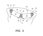
- FIG. 3 is an enlarged plan view of a pair of magnet insertion holes 24, 26 formed in the rotor core 10.
- the rotor core 10 shown in FIG. 1 is equivalent to the cross section along the line B-B in FIG. 2 .
- the rotor core 10 forming a cylindrical shape is constructed by laminating a plurality of magnetic steel plates 16, that have been formed by being punched into ring shapes, in the axial direction.
- Each of the magnetic steel plate 16 are integrally connected to each other by coupling fastening indent sections 18 that have been deformed by being pushed in locally.
- a plurality (8 in this embodiment) of the fastening indent sections 18 are formed at equal intervals in the circumferential direction.
- two keys 14 projecting opposite to each other in the radial direction are formed on an inner surface of the rotor core 10, extending in the axial direction.
- a plurality of permanent magnets 20 are embedded in a core inner section in the vicinity of the outer peripheral surface of the rotor core 10, arranged equally in the circumferential direction.
- the rotor core 10 has 8 magnetic poles 22 arranged equally in the circumferential direction, and each magnetic pole 22 is constructed using a pair of permanent magnets 20 that have been embedded forming substantially a 'V' shape.
- the pairs of permanent magnets 20 constituting each magnetic pole 22 respectively have a flat rectangular end surface shape and cross-sectional shape, and have substantially the same length as or a slightly shorter length than the rotor core 10.
- pairs of permanent magnets 20 are arranged so that each of facing end sections close to the circumferential direction are respectively slightly offset toward the center of the rotor core 10, so that pairs of permanent magnets 20 spread in a substantially 'V' shape towards the outer peripheral surface of the rotor core 10.
- the pairs of permanent magnets 20 are respectively arranged inside pairs of magnet insertion holes 24, 26, that are formed in correspondence with each of the magnetic poles 22.
- the above described substantially 'V' shaped arrangement of the pair of permanent magnets 20 is realized by the arrangement of these magnet insertion holes 24, 26.
- the magnet insertion holes 24, 26 are formed extending in the axial direction of the rotor core 10, opening to both ends sections, in the axial direction, of the rotor core 10, and permanent magnets 20 can be inserted into the magnet insertion holes 24, 26 from either of these openings.
- FIG. 3 is an expanded plan view of the magnet insertion holes 24, 26 into which permanent magnets 20 are respectively inserted.
- Magnet insertion holes 24, 26 are formed in mirror symmetrical shapes and positions on both sides of a magnetic pole center line M that runs between them in a radial direction, and so the following description is given for one of the magnet insertion holes 24, and description of the other magnet insertion hole 26 is omitted due to being incorporated herein by reference.
- the magnet insertion hole 24 is mainly formed from a magnet housing section 30 in which a permanent magnet 20 having a flat rectangular shaped is inserted and housed, but the magnet insertion hole 24 also includes resin filling holes 32, 34 respectively formed passing through on both sides in the long side direction of the permanent magnet 20.
- the appearance of a resin material 36 having been filled into the resin filling holes 32, 34 is shown by crosshatching in FIG. 3 .
- the resin material 36 is filled in by injection molding etc. after the permanent magnet 20 has been inserted into the magnet housing section 30, and fulfills a function of fixing the permanent magnet 20 inside the magnet insertion hole 24.
- the resin material 36 can be filled into a narrow gap between the side surface of a permanent magnet 20 and an inner wall surface of a magnet housing section 30, or can be filled so as to close up opening sections of the magnet insertion hole 24 that open to the axial direction end section 11a and/or 11b of the rotor core 10.
- One resin filling hole 32 is formed extending towards the outer peripheral surface 11c of the rotor core 10, effectively forming a first bridge section 38 where width of the magnetic steel plate 16 between the outer peripheral surface 11c of the rotor core 10 and the inner wall surface of the resin filling hole 32 becomes narrow.
- the other resin filling hole 34 is formed extending towards the other magnet insertion hole 26 that makes up the pair, effectively forming a second bridge section 40 where width of the magnetic steel plate 16 between the two magnet insertion holes 24 and 26 becomes narrow.
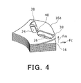
- a rotor 1 is formed by attaching the rotor core 10 that has permanent magnets 20 fixed inside magnet insertion holes 12, as described above, to the rotor shaft 2, and at the time of assembling this rotor 1 in a motor, as shown in FIG. 4 , a repulsion force Fm based on a repulsive magnetic force occurs between adjacent magnetic steel plates as a result of magnetic flux passing through from the permanent magnets 20.
- This repulsion force Fm is not a problem for magnetic steel plates 16 positioned in the center, in the axial direction, of the rotor core 10, but with a plurality of magnetic steel plates 16, 16a, positioned in the axial direction end sections 11a, 11b, of the rotor core 10, particularly the magnetic steel plate 16a that is at the outermost position in the axial direction, an outer peripheral section of the magnetic steel plate 16a is subjected to warping deformation, bending away from an adjacent magnetic steel plate 16, due to the repulsion force Fm.
- the fact that the end plates 3 have been made smaller in diameter than the rotor core 10 may be the reason why a pressing force does not act on outer peripheral sections of the magnetic steel plates 16.
- each of the magnetic steel plate 16 constituting the rotor core 10 extends along the radial directions resulting in a state where all of the magnetic steel plates 16 are in contact with each other, including the magnetic steel plate 16a that has the above-described deformation corrected.
- the plurality of magnetic steel plates 16, including the magnetic steel plates 16a positioned at the axial direction end sections 11a, 11b of the rotor core 10, are fixed by welding at inner wall surfaces of the first bridge section 38, specifically at an inner wall surface of the resin filling holes 32 forming part of the magnet insertion hole 24.
- inner wall surfaces of resin filling holes 32 of magnetic insertion holes 24, 26 are welded by laser welding, for example, to form welded sections 42, and outer peripheral sections of a plurality of magnetic steel plates that are respectively positioned at axial direction end sections 11a, 11b are connected together by the welded sections 42.
- the welding method is not restricted to laser welding, and it is also possible to use another welding method such as gas welding or electrical welding for example.
- the laser welding it is possible to appropriately set the axial length w of the welded section 42, that is, the number of magnetic steel plates that are connected by welding the first bridge sections 38 together, by adjusting the size of a spot of a laser beam L, or adjusting a distance over which a laser beam L, that is irradiated at an angle in the axial direction, moves in the direction of arrow D (axial direction).
- the welded sections 42 correspond to the first bridge section 38, or the vicinity thereof, where width of the magnetic steel plates 16 between the outer surface 11c of the rotor core 10 and the inner wall surface of the magnet insertion holes 24, 26 becomes narrow, it is possible to effectively reinforce the first bridge section 38, which is a section most likely to be damaged, by connection of the plurality of magnetic steel plates by welding.
- the welding sections 42 are only provided on both ends 11a, 11b sides of the rotor core 10 in the axial direction. As a result, it is possible to suppress increase in manufacturing cost of the rotor core 10 compared to the case of welding along the entire length in the axial direction of the rotor core 10.
- the welded section 42 is a part of the inner wall surface of the resin filling hole 32, and this hole 32, which is filled with resin material 36 for fixing the permanent magnets 20, also functions as a flux leakage suppression section for suppressing flux leakage at long side end sections (specifically the vicinity of the short side section) of the permanent magnets where magnetic permeability becomes low similar to that of empty space.
- the first bridge section 38 that faces this resin filling hole 32 is a section where magnetic flux from the permanent magnet 20 does not pass, and a section where there is no effect on the magnetic characteristics of the magnetic steel plates 16, 16a constituting the rotor core 10. Accordingly, the welding section 42 provided on this type of section will not exert any negative influence on the magnetic characteristics of the permanent magnets 20.
- FIG. 6 is a block diagram showing a manufacturing method for the rotor core 10.
- a cylindrical rotor core 10 is formed by laminating magnetic steel plates 16 that have respectively been formed by punch processing and integrally connecting them by caulking and the like.
- a welded section 42 is formed by laser welding an inner wall surface of a first bridge section 38 of the rotor core 10, and a plurality of magnetic steel plates 16 respectively positioned on the axial direction end sections 11a, 11b sides are connected at outer peripheral sections of the magnet steel plate.
- step S14 permanent magnets 20 are inserted into magnet insertion holes 24, 26 of the rotor core 10.
- step S16 resin material 36 is then filled into the magnet insertion holes 24, 26, and the permanent magnets 20 are fixed. In this way manufacture of the rotor core 10 is completed.
Landscapes
- Engineering & Computer Science (AREA)
- Power Engineering (AREA)
- Manufacturing & Machinery (AREA)
- Manufacture Of Motors, Generators (AREA)
- Permanent Field Magnets Of Synchronous Machinery (AREA)
- Iron Core Of Rotating Electric Machines (AREA)
Abstract
Description
- The present invention relates to a rotor core for a rotating electrical machine, and a manufacturing method thereof, and in particular relates to a rotor core for a rotating electrical machine constructed by integrally coupling magnetic steel plates by laminating, and to a manufacturing method thereof.
- Conventionally, a rotating electrical machine (hereafter referred to appropriately as a motor) has been known as an electric motor for converting electrical energy into mechanical force, or an electrical generator for carrying out the opposite conversion. A motor generally comprises a substantially cylindrical stator having coils respectively wound around a plurality of teeth sections that are formed projecting inwards, and a rotor provided capable of rotation inside the stator.
- As the rotor, the structure shown in
FIG. 7 , for example, is known. Thisrotor 50 comprises arotor core 52 forming a cylindrical shape, arotor shaft 54 passing through a center part of therotor core 52,end plates 56 arranged in contact with both sides of therotor core 52 with respect to an axial direction of the rotor shaft 54 (and rotor core 52) shown by the arrow X, and afixing member 58 for fixing therotor core 54 and theend plates 56 on therotor shaft 56. - The
rotor core 52 is formed by integrally coupling a large number of magnetic steel plates, that have been respectively formed by punching silicon steel plate etc. into a circular shape, by laminating in an axial direction and fastening. Also, a plurality of magnets are formed inside therotor core 52, close to the outer periphery, by embedding a plurality ofpermanent magnets 60 at equal locations in the circumferential direction. - The
rotor shaft 54 is formed from a round steel bar, with aflange section 55 protruding outward in a radial direction formed on an outer periphery. This flange section is brought into contact with anend plate 56 when therotor 50 is assembled and functions as a contact section for setting an axial position of therotor core 52 on the rotor shaft. - The
end plate 60 is constructed using a circular plate having substantially the same outer shape as an axial direction end section of therotor core 52. It is common practice, in theend plate 60, to use as a metal an aluminium plate that is comparatively lightweight, inexpensive and easy to machine.End plates 56 provided on both sides of the rotor core in the axial direction have a function to hold down therotor core 52 from both sides, a function to correct imbalance of the rotor core, and a function to prevent thepermanent magnets 56 from coming away from therotor core 52 in the axial direction. - A
fixing member 58 includes a fastening section 62 formed in a cylindrical shape, and apressing section 64 projecting from one end portion of the fastening section 62 in a radial direction. Thefixing section 58 is fixed on therotor shaft 54 by fastening the fastening section 62 to therotor shaft 54 in a state where therotor core 52 and twoend plates 56 are pressed in the direction of theflange section 55 by thepressing section 64. In this way therotor core 52 becomes fixed to therotor shaft 54 together with theend plates 56. - The
end plate 60 is formed in a disk shape having substantially the same outer shape as an axial direction end section of therotor core 52, specifically a magnetic steel sheet constituting therotor core 52. By forming in this way, it is possible for theend plates 60 to cause a pressing force to act on the entire surface of the magnetic steel plate at both ends of therotor core 52 in the axial direction. - Differing from this, it is conceivable to lower cost by making the end plates of smaller diameter than the rotor core. In this case, since a pressing force in the axial direction does not act on outer peripheral sections of the magnetic steel plates positioned at both ends in the axial direction of the rotor core, as described above, it becomes an essential point to suppress how much outer peripheral sections of the magnetic steel plates open up with warping deformation towards the outside in the axial direction due to reactive magnetic force between adjacent magnetic steel plates.
- For example, Japanese patent Laid-open No.
2003-304670 embodiment 2 in the patent document 1), forming arotor core 22 and then carrying out welding by laser welding across the entire axial direction length of therotor core 22 at asurface 30 of a region between neighboring corner sections (bridge sections) of magnetic slots 28 is described and illustrated. -
- Patent Publication 1:
JP 2003-304670 A - As disclosed in
patent document 1 above, on the outer surface of a rotor core formed by laminating magnetic steel plates, if welding is performed in an axial direction of a rotor core then even if end plates positioned on both axial direction sides of the rotor core are made small in diameter each of the magnetic steel plates are connected by the welding, a problem of outer peripheral parts of the magnetic steel plates at the axial direction end section sides opening out by warping deformation towards axial direction outer ends is solved. - However, with
patent document 1, since welding is carried out at a desired region on the outer surface of the rotor core and non-magnetic regions are formed by warping, in a case where weld sections have been formed bulging out from the rotor outer surface outward in the radial direction, more processing manhours become necessary such as for removing those bulging sections, which causes an increase in manufacturing cost of the rotor core to be greater than the reduction in cost due to making the end plate small in diameter - An object of the present invention is to provide a rotor core for a rotating electrical machine, and a manufacturing method thereof, that can effectively prevent opening up of magnetic steel plates that are positioned at end section sides in an axial direction due to warping deformation to an outer side, even if end plates are made small in diameter etc, while suppressing increase in manufacturing cost.
- A rotor core for a rotating electrical machine of the present invention is a cylindrical rotor core for a rotating electrical machine having magnetic steel plates integrally connected by laminating in an axial direction, and having magnet insertion holes formed for inserting permanent magnets inside, wherein the magnet insertion holes are formed extending in the axial direction of a core inner section in the vicinity of an outer peripheral surface of the rotor core, and with openings formed in axial direction end sections of the rotor core, and a plurality of magnetic steel plates, including outermost magnetic steel plates in the axial direction in which the openings are formed, are fixed by welding at inner wall surfaces of the magnet insertion holes.
- A manufacturing method for a rotor core for a rotating electrical machine of the present invention comprises a step of forming a cylindrical rotor core by laminating annular magnetic steel plates in an axial direction and integrally connecting them, a step of fixing by welding a plurality of magnetic steel plates, that include outermost magnetic steel plates in an axial direction and have formed therein the openings of magnet insertion holes which extend in the axial direction in the vicinity of an outer peripheral surface of the rotor core and open at axial end sections of the rotor core, at inner wall surfaces of the magnet insertion holes corresponding to sections where width of the magnetic steel plates between the outer peripheral surface of the rotor core and an inner wall surface of the magnet insertion holes become narrow, or the vicinity thereof, a step of inserting permanent magnets into the magnet insertion holes of the rotor core from the openings, and a step of filling resin material between side surfaces of the permanent magnets and inner wall surfaces of the magnet insertion holes to fix the permanent magnets in the magnet insertion holes.
- According to the rotor core for a rotating electrical machine, and manufacturing method thereof, of the present invention, since a magnetic steel plate positioned at an outermost side in the axial direction of the rotor core and formed with openings of magnet insertion holes, and one or a plurality of steel plates adjacent to this magnetic steel plate are fixed by welding on inner wall surfaces of the magnet insertion holes that have been formed extending in the axial direction at a core inner section adjacent to the outer peripheral surface of the rotor core, it is possible to effectively prevent outer peripheral sections of the magnetic steel plates from opening up due to warping deformation towards the outer side in the axial direction, even if end plates are made smaller in diameter than the rotor core, by connecting outer peripheral sections of a plurality of magnetic steel plates at axial direction end sections by welding. Also, in this case, since welding is carried out not on the outer peripheral surface of the rotor core but on inner wall surfaces of magnet insertion holes formed in the rotor core, there is no need for processing such as removing bulging sections as in the case where welding is carried out on the outer peripheral surface of the rotor core, and thus it is possible to suppress increase in manufacturing cost of the rotor core.
-
-
FIG. 1 is a cross sectional drawing along an axial direction showing a rotor that uses a rotor core or a rotating electrical machine of one embodiment of the present invention. -
FIG. 2 is a perspective view of the rotor core shown inFIG. 1 . -
FIG. 3 is an enlarged plan view of a pair of magnet insertion holes formed in the rotor core. -
FIG. 4 is an enlarged drawing showing the appearance of a bulging portion formed by warping of an outer peripheral section of a magnetic steel plate positioned at an outermost side in the axial direction of the rotor core. -
FIG. 5A is a partial plan view of the rotor core. -
FIG. 5B is a cross sectional drawing along line C-C inFIG. 5A . -
FIG. 6 is a block diagram showing a manufacturing method for a rotor core that is one embodiment of the present invention. -
FIG. 7 is a drawing showing a rotor of the related art. - Embodiments of the present invention will be described in detail in the following with reference to the attached drawings. In this description specific shapes, materials, numerical values and directions etc. are examples for simplifying understanding of the present invention, and can be appropriately modified in line with intended purpose, objectives, specifications etc.
- Also, in the description below the rotor core has been described as being applied to a rotor of a motor, that is a rotating electrical machine, but the rotor can also be applied to a rotor for a rotating electrical machine other than the motor, such as an electrical generator.
-
FIG. 1 shows arotor 1 in which arotor core 10, which is one embodiment of the present invention, is incorporated. Therotor 1 comprises arotor shaft 2, therotor core 10 that is fixed to an outer periphery of therotor shaft 2, and theend plates 3 respectively arranged in contact with both ends surfaces of therotor core 10 in an axial direction of the rotor shaft 2 (and rotor core 10) shown by the arrow X. - The
rotor shaft 2 is integrally provided with a hollow, steppedcylindrical shaft section 4, asupport section 5 that protrudes in a radial direction from an outer periphery of theshaft section 4, and a substantiallycylindrical attachment section 6 that is connected to a tip end of thesupport section 5. - A
flange section 7 projects in the radial direction at one end section, in the axial direction, of theattachment section 6, for positioning therotor core 10 by means of theend plates 3. On the other hand, a hook shaped or flangedfastening section 8 for fastening therotor core 10 by means of theend plates 3 is integrally formed with the other end section, in the axial direction, of theattachment section 6. - Also,
key grooves 9 extending in the axial direction are formed in an outer peripheral surface of theattachment section 6rotor shaft 2, and by engagingrotor core keys 14 of the rotor core 10 (refer toFIG. 2 ) that will be described later, revolving of therotor core 10 with respect to therotor shaft 2 is regulated. - The
end plates 3 are formed of aluminium plates that form a ring, and have an internal diameter substantially corresponding to the outer diameter of theattachment section 6 of therotor shaft 2, and an outer diameter that is smaller than therotor core 10. With this embodiment, theend plates 3 have an outer diameter that substantially matches theflange section 7 of theattachment section 6. In this way, it is possible to reduce cost by making theend plates 3 smaller in diameter than therotor core 10, and also, since the end plates do not have a function to press the plurality of magnetic steel plates that constitute therotor core 10 in the radial direction at radially outer peripheral sections, it is possible to make the thickness of the end plates thinner than in the related art, which also contributes to cost reduction. - The above-described
rotor 1 is assembled as follows. First, anend plate 3 is attached on the outer periphery of theattachment section 6 of therotor shaft 2 by inserting from the direction of arrow A. Then, therotor core 10 is similarly equipped on theattachment section 6 of therotor shaft 2, and is positioned in a state sandwiching theend plates 3 together with theflange section 7. - Following that, after one
more end plate 3 has inserted theattachment section 6 of therotor shaft 2, by bending thefastening section 8 radially outwards while applying a pressing force in the direction of arrow A so that a specified axial direction fixing force acts on therotor core 10, therotor core 10 is fastened to therotor shaft 2 together with the twoend plates 3. - The fastening section for fixing the
rotor core 10 to therotor shaft 2 is not limited to being integrally formed with therotor shaft 2, and can also be constructed as a separate member to the rotor shaft. - Next, the
rotor core 10 will be described in detail with reference toFIG. 2 andFIG. 3 in addition toFig. 1 .FIG. 2 is a perspective drawing of therotor core 10, andFIG. 3 is an enlarged plan view of a pair of magnet insertion holes 24, 26 formed in therotor core 10. Therotor core 10 shown inFIG. 1 is equivalent to the cross section along the line B-B inFIG. 2 . - As shown in
FIG. 1 andFIG. 2 , therotor core 10 forming a cylindrical shape is constructed by laminating a plurality ofmagnetic steel plates 16, that have been formed by being punched into ring shapes, in the axial direction. Each of themagnetic steel plate 16 are integrally connected to each other by couplingfastening indent sections 18 that have been deformed by being pushed in locally. A plurality (8 in this embodiment) of thefastening indent sections 18 are formed at equal intervals in the circumferential direction. Also, twokeys 14 projecting opposite to each other in the radial direction are formed on an inner surface of therotor core 10, extending in the axial direction. - In the
rotor core 10, all of themagnetic steel plates 16 are being shown connected together by thefastening indent sections 18, but this is not limiting, and in a case where there are a lot ofmagnetic steel plates 16, for example, it is possible to integrally connect sets of plates, that have been connected by calking etc. for each of a plurality of divided blocks in the axial direction, by adhesion or the like. - A plurality of
permanent magnets 20 are embedded in a core inner section in the vicinity of the outer peripheral surface of therotor core 10, arranged equally in the circumferential direction. In detail, therotor core 10 has 8magnetic poles 22 arranged equally in the circumferential direction, and eachmagnetic pole 22 is constructed using a pair ofpermanent magnets 20 that have been embedded forming substantially a 'V' shape. The pairs ofpermanent magnets 20 constituting eachmagnetic pole 22 respectively have a flat rectangular end surface shape and cross-sectional shape, and have substantially the same length as or a slightly shorter length than therotor core 10. Also, the pairs ofpermanent magnets 20 are arranged so that each of facing end sections close to the circumferential direction are respectively slightly offset toward the center of therotor core 10, so that pairs ofpermanent magnets 20 spread in a substantially 'V' shape towards the outer peripheral surface of therotor core 10. - The pairs of
permanent magnets 20 are respectively arranged inside pairs of magnet insertion holes 24, 26, that are formed in correspondence with each of themagnetic poles 22. The above described substantially 'V' shaped arrangement of the pair ofpermanent magnets 20 is realized by the arrangement of these magnet insertion holes 24, 26. The magnet insertion holes 24, 26 are formed extending in the axial direction of therotor core 10, opening to both ends sections, in the axial direction, of therotor core 10, andpermanent magnets 20 can be inserted into the magnet insertion holes 24, 26 from either of these openings. -
FIG. 3 is an expanded plan view of the magnet insertion holes 24, 26 into whichpermanent magnets 20 are respectively inserted. Magnet insertion holes 24, 26 are formed in mirror symmetrical shapes and positions on both sides of a magnetic pole center line M that runs between them in a radial direction, and so the following description is given for one of the magnet insertion holes 24, and description of the othermagnet insertion hole 26 is omitted due to being incorporated herein by reference. - The
magnet insertion hole 24 is mainly formed from amagnet housing section 30 in which apermanent magnet 20 having a flat rectangular shaped is inserted and housed, but themagnet insertion hole 24 also includesresin filling holes permanent magnet 20. The appearance of aresin material 36 having been filled into the resin filling holes 32, 34 is shown by crosshatching inFIG. 3 . Theresin material 36 is filled in by injection molding etc. after thepermanent magnet 20 has been inserted into themagnet housing section 30, and fulfills a function of fixing thepermanent magnet 20 inside themagnet insertion hole 24. - The
resin material 36 can be filled into a narrow gap between the side surface of apermanent magnet 20 and an inner wall surface of amagnet housing section 30, or can be filled so as to close up opening sections of themagnet insertion hole 24 that open to the axialdirection end section 11a and/or 11b of therotor core 10. - One
resin filling hole 32 is formed extending towards the outerperipheral surface 11c of therotor core 10, effectively forming afirst bridge section 38 where width of themagnetic steel plate 16 between the outerperipheral surface 11c of therotor core 10 and the inner wall surface of theresin filling hole 32 becomes narrow. - The other
resin filling hole 34 is formed extending towards the othermagnet insertion hole 26 that makes up the pair, effectively forming asecond bridge section 40 where width of themagnetic steel plate 16 between the two magnet insertion holes 24 and 26 becomes narrow. - A
rotor 1 is formed by attaching therotor core 10 that haspermanent magnets 20 fixed inside magnet insertion holes 12, as described above, to therotor shaft 2, and at the time of assembling thisrotor 1 in a motor, as shown inFIG. 4 , a repulsion force Fm based on a repulsive magnetic force occurs between adjacent magnetic steel plates as a result of magnetic flux passing through from thepermanent magnets 20. This repulsion force Fm is not a problem formagnetic steel plates 16 positioned in the center, in the axial direction, of therotor core 10, but with a plurality ofmagnetic steel plates direction end sections rotor core 10, particularly themagnetic steel plate 16a that is at the outermost position in the axial direction, an outer peripheral section of themagnetic steel plate 16a is subjected to warping deformation, bending away from an adjacentmagnetic steel plate 16, due to the repulsion force Fm. The fact that theend plates 3 have been made smaller in diameter than therotor core 10 may be the reason why a pressing force does not act on outer peripheral sections of themagnetic steel plates 16. - Conversely, when the
rotor 1 of the above described motor is rotatably driven, a centrifugal force Fc comes into play, and each of themagnetic steel plate 16 constituting therotor core 10 extends along the radial directions resulting in a state where all of themagnetic steel plates 16 are in contact with each other, including themagnetic steel plate 16a that has the above-described deformation corrected. - By being repeatedly subjected to these types of warping deformation and extending deformation, at the plurality of
magnetic steel plate 16, including the above describedmagnetic steel plates 16a that are positioned at thesides rotor core 10, it becomes easy for outer peripheral sections of those steel plates to be damaged by fatigue, and in particular it is easy for damage to occur at the first andsecond bridge sections magnetic steel plates 16 becomes narrow and strength is lowered. - With the
rotor core 10 of this embodiment therefore, the plurality ofmagnetic steel plates 16, including themagnetic steel plates 16a positioned at the axialdirection end sections rotor core 10, are fixed by welding at inner wall surfaces of thefirst bridge section 38, specifically at an inner wall surface of the resin filling holes 32 forming part of themagnet insertion hole 24. - As shown in
FIG. 5A and FIG. 5B , with therotor core 10 havingmagnetic steel plates 16 integrally connected by laminating, before inserting thepermanent magnets 20, inner wall surfaces ofresin filling holes 32 of magnetic insertion holes 24, 26 are welded by laser welding, for example, to form weldedsections 42, and outer peripheral sections of a plurality of magnetic steel plates that are respectively positioned at axialdirection end sections sections 42. In this way, by also connecting the plurality ofmagnetic steel plates 16, including themagnetic steel plates 16a positioned outermost in the axial direction, at outer peripheral sections, strength and rigidity are increased, and as a result it is possible to prevent a state where themagnetic steel plates 16a bend upwards with warping deformation, even if the repulsion force Fm acts. Specifically, it is possible to reliably prevent damage to the first andsecond bridge sections - In the case where the laser welding is used, it is possible to appropriately set the axial length w of the welded
section 42, that is, the number of magnetic steel plates that are connected by welding thefirst bridge sections 38 together, by adjusting the size of a spot of a laser beam L, or adjusting a distance over which a laser beam L, that is irradiated at an angle in the axial direction, moves in the direction of arrow D (axial direction). - Also, since welding is carried out not on the outer
peripheral surface 11c of therotor core 10 but on inner wall surfaces ofresin filling holes 32 of magnet insertion holes 24, 26 formed in therotor core 10, there is no need for processing such as removing bulging section as in the case where welding is carried out on the outerperipheral surface 11c of therotor core 10, and it is possible to suppress increase in manufacturing cost of therotor core 10. Further, even if the weldedsections 42 form bulging sections, since they are at the inner wall surface of the resin filling holes 32, there is no interference to insertion of permanent magnets into the magnet insertion holes 24, 26. - Also, since the welded
sections 42 correspond to thefirst bridge section 38, or the vicinity thereof, where width of themagnetic steel plates 16 between theouter surface 11c of therotor core 10 and the inner wall surface of the magnet insertion holes 24, 26 becomes narrow, it is possible to effectively reinforce thefirst bridge section 38, which is a section most likely to be damaged, by connection of the plurality of magnetic steel plates by welding. - Also, the
welding sections 42 are only provided on bothends rotor core 10 in the axial direction. As a result, it is possible to suppress increase in manufacturing cost of therotor core 10 compared to the case of welding along the entire length in the axial direction of therotor core 10. - Further, the welded
section 42 is a part of the inner wall surface of theresin filling hole 32, and thishole 32, which is filled withresin material 36 for fixing thepermanent magnets 20, also functions as a flux leakage suppression section for suppressing flux leakage at long side end sections (specifically the vicinity of the short side section) of the permanent magnets where magnetic permeability becomes low similar to that of empty space. In other words, thefirst bridge section 38 that faces thisresin filling hole 32 is a section where magnetic flux from thepermanent magnet 20 does not pass, and a section where there is no effect on the magnetic characteristics of themagnetic steel plates rotor core 10. Accordingly, thewelding section 42 provided on this type of section will not exert any negative influence on the magnetic characteristics of thepermanent magnets 20. - Next, a manufacturing method for the above described
rotor core 10 will be simply described with reference toFIG 6. FIG. 6 is a block diagram showing a manufacturing method for therotor core 10. - As shown in
FIG. 6 , first, in step S10, acylindrical rotor core 10 is formed by laminatingmagnetic steel plates 16 that have respectively been formed by punch processing and integrally connecting them by caulking and the like. - Next, in step S12, a welded
section 42 is formed by laser welding an inner wall surface of afirst bridge section 38 of therotor core 10, and a plurality ofmagnetic steel plates 16 respectively positioned on the axialdirection end sections - Next, in step S14,
permanent magnets 20 are inserted into magnet insertion holes 24, 26 of therotor core 10. - In step
S16 resin material 36 is then filled into the magnet insertion holes 24, 26, and thepermanent magnets 20 are fixed. In this way manufacture of therotor core 10 is completed. - Description has been given above for a case where end plates are made smaller in diameter than the rotor core, but it is also possible to omit one or both of the end plates and to fasten both end sections in the axial direction of the rotor core by directly contacting at least one of a flange section and a fastening section of a rotor shaft.
-
- 1 Rotor
- 2 Rotor shaft
- 3 End plate
- 4 Shaft section
- 5 Support section
- 6 Attachment section
- 7 Flange section
- 8 Fastening section
- 9 Key groove
- 10 Rotor core
- 11a, 11b axial direction end section
- 11c Outer peripheral surface
- 12 Magnet insertion hole
- 14 Key
- 16, 16a Magnetic steel plate
- 18 Fastening indent
- 20 Permanent magnet
- 22 Magnetic pole
- 24, 26 pair of magnet insertion holes
- 30 Magnet housing section
- 32, 34 Resin filling hole
- 36 Resin material
- 38 1st bridge section
- 40 2nd bridge section
- 42 Welded section
- Fc centrifugal force
- Fm Repulsion force
- L Laser beam
Claims (7)
- A cylindrical rotor core for a rotating electrical machine, formed by laminating magnetic steel plates in an axial direction and integrally connecting them, and having formed therein magnet insertion holes for inserting permanent magnets inside, wherein
the magnet insertion holes are formed extending in the axial direction of a core inner section in the vicinity of an outer peripheral surface of the rotor core, and with openings formed in axial direction end sections of the rotor core, and a plurality of magnetic steel plates, including magnetic steel plates at outermost sides in the axial direction in which the openings are formed, are fixed by welding at inner wall surfaces of the magnet insertion holes. - The rotor core for a rotating electrical machine according to claim 1, wherein
a welded section of the inner wall surface of the magnet insertion holes corresponds to a section, or a vicinity thereof, where width of the magnetic steel plates between the outer peripheral surface of the rotor core and the inner wall surface of the magnet insertion holes becomes narrow. - The rotor core for a rotating electrical machine according to claim 1 or claim 2, wherein
a welded section of the inner wall surface of the magnet insertion holes is only provided on both end sides in the axial direction of the rotor core. - The rotor core for a rotating electrical machine according to any one of claim 1 to claim 3, wherein
the welded section of the inner wall surface of the magnet insertion holes is a section that does not have an effect on the magnetic characteristics of the magnetic steel plates constituting the rotor core. - The rotor core for a rotating electrical machine according to any one of claim 1 to claim 4, wherein
the welded section of the inner wall surface of the magnet insertion holes is a section on an inner wall surface of a resin filling hole that is filled with resin material for magnet fixing after the permanent magnets have been inserted, formed expanding toward the outer peripheral surface of the rotor core as part of the magnet insertion hole. - The rotor core for a rotating electrical machine according to in claim 5, wherein
the resin filling hole functions as a flux leakage restrictions section for restricting flux leakage that occurs at end sections of the permanent magnets. - A manufacturing method for a rotor core for a rotating electrical machine, comprising:a step of forming a cylindrical rotor core by laminating annular magnetic steel plates in an axial direction and integrally connecting them;a step of fixing by welding magnetic steel plates, that are positioned on outermost sides of an axial direction and have formed therein openings of magnet insertion holes which extend in the axial direction in the vicinity of an outer peripheral surface of the rotor core and open at axial end sections of the rotor core, to one or a plurality of adjacent magnetic steel plates, at inner wall surfaces of the magnet insertion holes corresponding to sections where width of the magnetic steel plates between the outer peripheral surface of the rotor core and an inner wall surface of the magnet insertion holes become narrow, or the vicinity thereof;a step of inserting permanent magnets into the magnet insertion holes of the rotor core from the openings; anda step of filling resin material between side surfaces of the permanent magnets and inner wall surfaces of the magnet insertion holes to fix the permanent magnets inside the magnet insertion holes.
Priority Applications (1)
| Application Number | Priority Date | Filing Date | Title |
|---|---|---|---|
| EP16175510.3A EP3091639B1 (en) | 2010-06-14 | 2010-06-14 | Rotor core for rotating electrical machine, and manufacturing method thereof |
Applications Claiming Priority (1)
| Application Number | Priority Date | Filing Date | Title |
|---|---|---|---|
| PCT/JP2010/060012 WO2011158316A1 (en) | 2010-06-14 | 2010-06-14 | Rotor core for dynamo-electric machine and method for manufacturing same |
Related Child Applications (1)
| Application Number | Title | Priority Date | Filing Date |
|---|---|---|---|
| EP16175510.3A Division EP3091639B1 (en) | 2010-06-14 | 2010-06-14 | Rotor core for rotating electrical machine, and manufacturing method thereof |
Publications (2)
| Publication Number | Publication Date |
|---|---|
| EP2582014A1 true EP2582014A1 (en) | 2013-04-17 |
| EP2582014A4 EP2582014A4 (en) | 2014-05-07 |
Family
ID=45347742
Family Applications (2)
| Application Number | Title | Priority Date | Filing Date |
|---|---|---|---|
| EP16175510.3A Active EP3091639B1 (en) | 2010-06-14 | 2010-06-14 | Rotor core for rotating electrical machine, and manufacturing method thereof |
| EP10853198.9A Withdrawn EP2582014A4 (en) | 2010-06-14 | 2010-06-14 | ROTOR CORE FOR DYNAMOELECTRIC MACHINE AND METHOD FOR MANUFACTURING THE SAME |
Family Applications Before (1)
| Application Number | Title | Priority Date | Filing Date |
|---|---|---|---|
| EP16175510.3A Active EP3091639B1 (en) | 2010-06-14 | 2010-06-14 | Rotor core for rotating electrical machine, and manufacturing method thereof |
Country Status (5)
| Country | Link |
|---|---|
| US (1) | US9154005B2 (en) |
| EP (2) | EP3091639B1 (en) |
| JP (1) | JP5278551B2 (en) |
| CN (1) | CN103004056B (en) |
| WO (1) | WO2011158316A1 (en) |
Cited By (2)
| Publication number | Priority date | Publication date | Assignee | Title |
|---|---|---|---|---|
| DE102016209146A1 (en) | 2016-05-25 | 2017-11-30 | Robert Bosch Gmbh | Rotor of an electric machine |
| EP4576503A4 (en) * | 2022-10-31 | 2025-10-01 | Aisin Corp | Rotor for rotary electric machine |
Families Citing this family (33)
| Publication number | Priority date | Publication date | Assignee | Title |
|---|---|---|---|---|
| US8766502B2 (en) * | 2011-09-27 | 2014-07-01 | Lg Innotek Co., Ltd. | Rotor having shaft slip inhibition structure and motor having the same |
| JP6069695B2 (en) * | 2012-11-02 | 2017-02-01 | 日産自動車株式会社 | Rotor for motor |
| JP5722301B2 (en) * | 2012-12-18 | 2015-05-20 | ファナック株式会社 | Embedded magnet type synchronous motor rotor and embedded magnet type synchronous motor |
| JP5892106B2 (en) * | 2013-04-15 | 2016-03-23 | 株式会社安川電機 | Rotating electric machine and method of manufacturing rotor |
| JP6017067B2 (en) * | 2013-12-13 | 2016-10-26 | 三菱電機株式会社 | Permanent magnet embedded rotary electric machine |
| JP6123716B2 (en) * | 2014-03-20 | 2017-05-10 | トヨタ自動車株式会社 | Rotor |
| US10211688B2 (en) | 2014-06-06 | 2019-02-19 | Komatsu Ltd. | Electric machine |
| JP6101733B2 (en) * | 2015-04-20 | 2017-03-22 | 本田技研工業株式会社 | Rotating electrical machine rotor |
| KR102446182B1 (en) * | 2015-05-27 | 2022-09-22 | 엘지이노텍 주식회사 | a rotor and a motor comprising the rotor |
| DE102015213609A1 (en) * | 2015-07-20 | 2017-01-26 | Siemens Aktiengesellschaft | Highly dynamic operable rotor for an electric machine |
| JP6696564B2 (en) * | 2016-03-14 | 2020-05-20 | アイシン・エィ・ダブリュ株式会社 | Rotor manufacturing method |
| US11271459B2 (en) * | 2016-03-28 | 2022-03-08 | Aisin Corporation | Rotor manufacturing method |
| JP6685175B2 (en) * | 2016-05-24 | 2020-04-22 | 日立オートモティブシステムズ株式会社 | Rotating electric machine |
| US10411537B2 (en) * | 2016-08-22 | 2019-09-10 | American Axle & Manufacturing, Inc. | Rotor lamination and related rotor and electric motor incorporating same |
| DE112017004437T5 (en) * | 2016-12-26 | 2019-06-19 | Aisin Aw Co., Ltd. | ROTOR CORE MANUFACTURING METHOD AND ROTOR CORE |
| CN110431735B (en) * | 2017-03-31 | 2021-06-04 | 爱信艾达株式会社 | Core manufacturing method and core |
| WO2019176543A1 (en) * | 2018-03-16 | 2019-09-19 | 株式会社三井ハイテック | Method for manufacturing iron core product, iron core product, and method for manufacturing rotor |
| WO2019195743A1 (en) * | 2018-04-06 | 2019-10-10 | Maxwell Daryl Wayne | Laser pin welded electrical lamination core and method |
| JP7103057B2 (en) * | 2018-08-23 | 2022-07-20 | トヨタ自動車株式会社 | Rotor core and its manufacturing method |
| JP7310141B2 (en) * | 2019-01-08 | 2023-07-19 | トヨタ紡織株式会社 | Rotor of rotary electric machine |
| JP7393347B2 (en) * | 2019-01-11 | 2023-12-06 | 日本発條株式会社 | Rotor manufacturing method |
| JP7112340B2 (en) * | 2019-01-21 | 2022-08-03 | 本田技研工業株式会社 | Rotor of rotating electric machine and rotating electric machine |
| DE102019202267A1 (en) * | 2019-02-20 | 2020-08-20 | Robert Bosch Gmbh | Rotor of an electrical machine, and also electrical machine having such a rotor |
| EP3758195A1 (en) * | 2019-06-27 | 2020-12-30 | General Electric Company | Permanent magnet machine |
| EP4068575A4 (en) * | 2019-11-25 | 2023-01-11 | Kabushiki Kaisha Toyota Jidoshokki | ROTOR FOR A DYNAMO-ELECTRIC MACHINE |
| CN110957827A (en) * | 2019-12-03 | 2020-04-03 | 重庆宝迪科技有限公司 | Rotor punching sheet structure beneficial to ensuring magnetic circuit symmetry |
| US12136853B2 (en) * | 2019-12-09 | 2024-11-05 | Mitsubishi Electric Corporation | Electric-rotating-machine rotor and manufacturing method therefor |
| CN111200324B (en) * | 2020-01-16 | 2021-09-28 | 中国第一汽车股份有限公司 | Motor rotor punching sheet, motor rotor, motor and new energy vehicle |
| FR3108803B1 (en) * | 2020-03-25 | 2022-03-11 | Novares France | Rotor for electric motor incorporating sound absorption elements |
| JP7613151B2 (en) * | 2021-02-24 | 2025-01-15 | ニデック株式会社 | ROTOR, ROTATING ELECTRIC MACHINE, AND DRIVE DEVICE |
| EP4507168A4 (en) * | 2022-04-01 | 2025-12-31 | Toshiba Kk | INTERNAL PERMANENT MAGNETIC ROTOR AND ELECTRIC LATHE |
| US12206288B2 (en) * | 2022-08-09 | 2025-01-21 | GM Global Technology Operations LLC | Rotor for an electric machine |
| JP2024130462A (en) | 2023-03-15 | 2024-09-30 | 株式会社三井ハイテック | Laminated core and method of manufacturing laminated core |
Family Cites Families (15)
| Publication number | Priority date | Publication date | Assignee | Title |
|---|---|---|---|---|
| JPH09247908A (en) * | 1996-03-06 | 1997-09-19 | Toshiba Corp | Iron core and iron core manufacturing method and manufacturing apparatus |
| US5811904A (en) * | 1996-03-21 | 1998-09-22 | Hitachi, Ltd. | Permanent magnet dynamo electric machine |
| JP3308828B2 (en) * | 1996-10-18 | 2002-07-29 | 株式会社日立製作所 | Permanent magnet rotating electric machine and electric vehicle using the same |
| JPH1118324A (en) * | 1997-06-19 | 1999-01-22 | Toyota Motor Corp | Rotating machine and its manufacture |
| JP2001057747A (en) | 1999-08-12 | 2001-02-27 | Sankyo Seiki Mfg Co Ltd | Motor laminated core, method of manufacturing the same, and motor |
| JP2002345189A (en) * | 2001-05-11 | 2002-11-29 | Nissan Motor Co Ltd | Permanent magnet embedded synchronous motor |
| JP2003304670A (en) | 2002-04-09 | 2003-10-24 | Toyota Motor Corp | Method of manufacturing rotor for rotating machine |
| JP3951905B2 (en) * | 2002-04-25 | 2007-08-01 | 日産自動車株式会社 | Magnetic steel sheet forming body for rotor core, rotor for built-in permanent magnet type rotating electric machine using the same, method for producing electromagnetic steel sheet forming body for rotor core, and permanent magnet built-in type rotating electric machine |
| CN1617429A (en) * | 2004-11-24 | 2005-05-18 | 宁波市宝捷机电有限公司 | Processing method for coiled motor iron core |
| US7495364B2 (en) * | 2004-12-03 | 2009-02-24 | Emerson Electric Co. | Cryogenic pumping systems, rotors and methods for pumping cryogenic fluids |
| JP4143631B2 (en) * | 2005-09-01 | 2008-09-03 | トヨタ自動車株式会社 | Manufacturing method of rotor |
| JP4898201B2 (en) | 2005-12-01 | 2012-03-14 | アイチエレック株式会社 | Permanent magnet rotating machine |
| JP4856990B2 (en) * | 2006-03-13 | 2012-01-18 | トヨタ自動車株式会社 | Rotor, method for manufacturing the same, and electric vehicle |
| CN101098091A (en) * | 2006-12-28 | 2008-01-02 | 刘连兵 | Permanent-magnet arc welding alternator rotor |
| JP4626683B2 (en) * | 2007-08-29 | 2011-02-09 | トヨタ自動車株式会社 | Steel material having nonmagnetic portion, method for manufacturing the same, and rotating electric machine core |
-
2010
- 2010-06-14 EP EP16175510.3A patent/EP3091639B1/en active Active
- 2010-06-14 JP JP2011523635A patent/JP5278551B2/en active Active
- 2010-06-14 CN CN201080063486.3A patent/CN103004056B/en active Active
- 2010-06-14 WO PCT/JP2010/060012 patent/WO2011158316A1/en not_active Ceased
- 2010-06-14 US US13/503,760 patent/US9154005B2/en active Active
- 2010-06-14 EP EP10853198.9A patent/EP2582014A4/en not_active Withdrawn
Cited By (3)
| Publication number | Priority date | Publication date | Assignee | Title |
|---|---|---|---|---|
| DE102016209146A1 (en) | 2016-05-25 | 2017-11-30 | Robert Bosch Gmbh | Rotor of an electric machine |
| WO2017202518A1 (en) | 2016-05-25 | 2017-11-30 | Robert Bosch Gmbh | Rotor of an electric machine |
| EP4576503A4 (en) * | 2022-10-31 | 2025-10-01 | Aisin Corp | Rotor for rotary electric machine |
Also Published As
| Publication number | Publication date |
|---|---|
| CN103004056B (en) | 2015-03-25 |
| CN103004056A (en) | 2013-03-27 |
| EP2582014A4 (en) | 2014-05-07 |
| JP5278551B2 (en) | 2013-09-04 |
| EP3091639B1 (en) | 2018-09-05 |
| WO2011158316A1 (en) | 2011-12-22 |
| US9154005B2 (en) | 2015-10-06 |
| EP3091639A1 (en) | 2016-11-09 |
| JPWO2011158316A1 (en) | 2013-08-15 |
| US20120206007A1 (en) | 2012-08-16 |
Similar Documents
| Publication | Publication Date | Title |
|---|---|---|
| US9154005B2 (en) | Rotor core for rotating electrical machine, and manufacturing method thereof | |
| JP4807219B2 (en) | Stator core and rotating electric machine | |
| US8729760B2 (en) | Rotor of electric motor having structure for attaching magnet securely to outer circumferential surface of rotor core and manufacturing method thereof | |
| US10439453B2 (en) | Stator | |
| JP5040988B2 (en) | Stator and motor provided with the stator | |
| JP2012120326A (en) | Interior magnet rotor, motor, and method for assembling motor | |
| JP2015163006A (en) | Rotating electric machine and manufacturing method thereof | |
| WO2009093524A1 (en) | Laminated iron core for rotor | |
| JPH08196061A (en) | Laminated iron core for stator | |
| WO2017141562A1 (en) | Rotating electric machine stator, rotating electric machine, and method for manufacturing rotating electric machine stator | |
| JP2011030320A (en) | Dynamo-electric machine and method of manufacturing the same | |
| JP4286642B2 (en) | Permanent magnet rotor | |
| JP2012125111A (en) | Rotor of outer rotor type rotary machine | |
| JP2019180214A (en) | motor | |
| JP5376262B2 (en) | Stator for rotating electric machine and method for manufacturing the same | |
| JP2012130205A (en) | Core of rotary electric machine and manufacturing method of the same | |
| JP4062938B2 (en) | Motor stator core assembly and method of assembling stator assembly | |
| JP2017225208A (en) | Armature, rotary electric machine, and manufacturing method of armature | |
| CN114977565B (en) | Rotor and IPM motor | |
| JP2017022849A (en) | Rotating electrical machine rotor | |
| JP2007195281A (en) | Stator core for rotating electrical machine and stator using the stator core | |
| JP5033320B2 (en) | Method for manufacturing stator of electric motor | |
| JP2012105543A (en) | Stator for electric motor | |
| JP2013102575A (en) | Rotary electric machine | |
| JP4042623B2 (en) | Split core type stator |
Legal Events
| Date | Code | Title | Description |
|---|---|---|---|
| PUAI | Public reference made under article 153(3) epc to a published international application that has entered the european phase |
Free format text: ORIGINAL CODE: 0009012 |
|
| 17P | Request for examination filed |
Effective date: 20120326 |
|
| AK | Designated contracting states |
Kind code of ref document: A1 Designated state(s): AL AT BE BG CH CY CZ DE DK EE ES FI FR GB GR HR HU IE IS IT LI LT LU LV MC MK MT NL NO PL PT RO SE SI SK SM TR |
|
| DAX | Request for extension of the european patent (deleted) | ||
| A4 | Supplementary search report drawn up and despatched |
Effective date: 20140408 |
|
| RIC1 | Information provided on ipc code assigned before grant |
Ipc: H02K 1/22 20060101AFI20140402BHEP |
|
| 17Q | First examination report despatched |
Effective date: 20150211 |
|
| STAA | Information on the status of an ep patent application or granted ep patent |
Free format text: STATUS: THE APPLICATION IS DEEMED TO BE WITHDRAWN |
|
| 18D | Application deemed to be withdrawn |
Effective date: 20160623 |